EP1616135B1 - Methods for detecting surge in centrifugal compressors - Google Patents
Methods for detecting surge in centrifugal compressors Download PDFInfo
- Publication number
- EP1616135B1 EP1616135B1 EP04760017.6A EP04760017A EP1616135B1 EP 1616135 B1 EP1616135 B1 EP 1616135B1 EP 04760017 A EP04760017 A EP 04760017A EP 1616135 B1 EP1616135 B1 EP 1616135B1
- Authority
- EP
- European Patent Office
- Prior art keywords
- temperature
- compressor
- evaporator
- refrigerant
- surge
- Prior art date
- Legal status (The legal status is an assumption and is not a legal conclusion. Google has not performed a legal analysis and makes no representation as to the accuracy of the status listed.)
- Expired - Lifetime
Links
- 238000000034 method Methods 0.000 title claims description 18
- 239000003507 refrigerant Substances 0.000 claims description 26
- 238000005057 refrigeration Methods 0.000 claims description 19
- 239000007788 liquid Substances 0.000 claims description 9
- 239000012530 fluid Substances 0.000 claims 9
- XLYOFNOQVPJJNP-UHFFFAOYSA-N water Substances O XLYOFNOQVPJJNP-UHFFFAOYSA-N 0.000 description 15
- 238000009529 body temperature measurement Methods 0.000 description 9
- 238000001514 detection method Methods 0.000 description 9
- 238000012544 monitoring process Methods 0.000 description 9
- 239000012809 cooling fluid Substances 0.000 description 6
- 238000001816 cooling Methods 0.000 description 3
- 238000010586 diagram Methods 0.000 description 3
- 230000001052 transient effect Effects 0.000 description 2
- 238000013459 approach Methods 0.000 description 1
- 230000001276 controlling effect Effects 0.000 description 1
- 238000007689 inspection Methods 0.000 description 1
- 238000012423 maintenance Methods 0.000 description 1
- 230000001105 regulatory effect Effects 0.000 description 1
- 230000000630 rising effect Effects 0.000 description 1
- 229920006395 saturated elastomer Polymers 0.000 description 1
- 230000009885 systemic effect Effects 0.000 description 1
- 230000001960 triggered effect Effects 0.000 description 1
- 238000011144 upstream manufacturing Methods 0.000 description 1
Images


Classifications
-
- F—MECHANICAL ENGINEERING; LIGHTING; HEATING; WEAPONS; BLASTING
- F04—POSITIVE - DISPLACEMENT MACHINES FOR LIQUIDS; PUMPS FOR LIQUIDS OR ELASTIC FLUIDS
- F04D—NON-POSITIVE-DISPLACEMENT PUMPS
- F04D27/00—Control, e.g. regulation, of pumps, pumping installations or pumping systems specially adapted for elastic fluids
- F04D27/001—Testing thereof; Determination or simulation of flow characteristics; Stall or surge detection, e.g. condition monitoring
-
- F—MECHANICAL ENGINEERING; LIGHTING; HEATING; WEAPONS; BLASTING
- F04—POSITIVE - DISPLACEMENT MACHINES FOR LIQUIDS; PUMPS FOR LIQUIDS OR ELASTIC FLUIDS
- F04D—NON-POSITIVE-DISPLACEMENT PUMPS
- F04D27/00—Control, e.g. regulation, of pumps, pumping installations or pumping systems specially adapted for elastic fluids
- F04D27/02—Surge control
-
- F—MECHANICAL ENGINEERING; LIGHTING; HEATING; WEAPONS; BLASTING
- F25—REFRIGERATION OR COOLING; COMBINED HEATING AND REFRIGERATION SYSTEMS; HEAT PUMP SYSTEMS; MANUFACTURE OR STORAGE OF ICE; LIQUEFACTION SOLIDIFICATION OF GASES
- F25B—REFRIGERATION MACHINES, PLANTS OR SYSTEMS; COMBINED HEATING AND REFRIGERATION SYSTEMS; HEAT PUMP SYSTEMS
- F25B1/00—Compression machines, plants or systems with non-reversible cycle
- F25B1/04—Compression machines, plants or systems with non-reversible cycle with compressor of rotary type
-
- F—MECHANICAL ENGINEERING; LIGHTING; HEATING; WEAPONS; BLASTING
- F25—REFRIGERATION OR COOLING; COMBINED HEATING AND REFRIGERATION SYSTEMS; HEAT PUMP SYSTEMS; MANUFACTURE OR STORAGE OF ICE; LIQUEFACTION SOLIDIFICATION OF GASES
- F25B—REFRIGERATION MACHINES, PLANTS OR SYSTEMS; COMBINED HEATING AND REFRIGERATION SYSTEMS; HEAT PUMP SYSTEMS
- F25B2500/00—Problems to be solved
- F25B2500/19—Calculation of parameters
-
- F—MECHANICAL ENGINEERING; LIGHTING; HEATING; WEAPONS; BLASTING
- F25—REFRIGERATION OR COOLING; COMBINED HEATING AND REFRIGERATION SYSTEMS; HEAT PUMP SYSTEMS; MANUFACTURE OR STORAGE OF ICE; LIQUEFACTION SOLIDIFICATION OF GASES
- F25B—REFRIGERATION MACHINES, PLANTS OR SYSTEMS; COMBINED HEATING AND REFRIGERATION SYSTEMS; HEAT PUMP SYSTEMS
- F25B2700/00—Sensing or detecting of parameters; Sensors therefor
- F25B2700/21—Temperatures
- F25B2700/2115—Temperatures of a compressor or the drive means therefor
- F25B2700/21151—Temperatures of a compressor or the drive means therefor at the suction side of the compressor
-
- F—MECHANICAL ENGINEERING; LIGHTING; HEATING; WEAPONS; BLASTING
- F25—REFRIGERATION OR COOLING; COMBINED HEATING AND REFRIGERATION SYSTEMS; HEAT PUMP SYSTEMS; MANUFACTURE OR STORAGE OF ICE; LIQUEFACTION SOLIDIFICATION OF GASES
- F25B—REFRIGERATION MACHINES, PLANTS OR SYSTEMS; COMBINED HEATING AND REFRIGERATION SYSTEMS; HEAT PUMP SYSTEMS
- F25B2700/00—Sensing or detecting of parameters; Sensors therefor
- F25B2700/21—Temperatures
- F25B2700/2117—Temperatures of an evaporator
- F25B2700/21174—Temperatures of an evaporator of the refrigerant at the inlet of the evaporator
Definitions
- the present invention generally relates to chiller systems. More specifically, the present invention relates to methods for detecting surge in a centrifugal compressor integral to a refrigeration system.
- Surging is an unstable operating condition that occurs in compressors, including centrifugal compressors used in refrigeration systems. Such a condition can be caused by an increase or decrease in compressor discharge pressure or by a reduction in the flow of gas to the compressor. These events can be triggered by poor maintenance of the refrigeration system, failure of a system component, or human error. Excessive surging, either in number of occurrences or in magnitude, may result in damage or complete failure of the compressor. Surging also results in inefficiencies in operation of a refrigeration system that result in excessive power consumption.
- Extreme surging may be detectable by inspection of an operating compressor, by those knowledgeable in the art, but a compressor can operate in a surge condition with little vibration experienced.
- Different methods of detecting surge conditions in centrifugal compressors are known in the art.
- One method of detecting surge in a compressor is to monitor vibration of the compressor by mounting a vibration detector on or near the compressor to sense vibration caused by the compressor in a surged condition. Shortcomings of this method include the need for an extremely sensitive vibration sensor and false surge indications during start-up of the compressor.
- Another method of detecting surge is by monitoring flow and pressure differences in the vicinity of the compressor as disclosed in U. S. Patent No. 3,555, 844 .
- An alternative means of detecting surge is disclosed in U. S. Patent No.2,696, 345 , which teaches monitoring temperature upstream of the impeller to detect an increase in temperature that precedes major surging. That same patent discloses a method of detecting surge by monitoring temperature on the discharge side of an axial flow compressor.
- monitoring temperature in the discharge is not effective in a refrigerant compressor because the discharge temperature of such a compressor will actually go down when the compressor is in surge, since the flow to the discharge is basically stopped.
- U. S. Patent No. 4,363, 596 teaches a method of detecting surge by measuring a temperature rise beyond a predetermined value in a space in the impeller chamber of the compressor, exterior of the flow path of gas through the impeller.
- the specification states that the temperature rise, above the normal operating temperature, occurring when the compressor is surging is caused by the increased heat produced by reduced compressor efficiency and the inability of the reduced gas flow to remove the heat.
- the disadvantage of this approach is that it measures the temperature rise in one location inside the impeller chamber and does not take into account that the temperature at the location may change due to a change in the operation condition of the compressor even when there is no surge. For example, a start-up condition is likely to give a false surge reading.
- a control system effectively maximizes efficiency without encountering surge problems by monitoring the temperature of the refrigerant in the condenser discharge line, the temperature of the saturated refrigerant leaving the evaporator, the temperature of the chilled water discharged from the evaporator of the chiller, and the inlet guide vane position. Based on the foregoing four parameters and a set point temperature input, the control system described in U. S. Patent No. 4,151, 725 effectively regulates the refrigeration system by regulating the speed of the compressor and adjusting vane position. A person skilled in the art will recognize that the temperatures being measured are unlikely to be influenced by incipient surge.
- U. S. Patent No. 5,746, 062 discloses the method of detecting surges in a centrifugal compressor via sensing suction and discharge pressures of the compressor.
- the same patent also discloses surge detection through monitoring of the current applied to the variable speed motor drive that drives the compressor. It will be readily apparent to one skilled in the art that a sudden change in the load on the system, not necessarily related to surge, could also influence the current applied to the motor thus increasing the likelihood of a false positive detection of surge.
- This patent also teaches utilizing both pressure sensing and current sensing techniques to detect a surge.
- the present invention incorporates the use of operating conditions beyond the immediate vicinity of a centrifugal compressor of a refrigeration system to provide an accurate method of detecting surge in the compressor.
- One aspect of the present invention utilizes sensors to monitor the temperature differential between the suction temperature at the entrance to the compressor impeller and the evaporator water temperature.
- Another aspect of the invention compares the temperature differential between the suction temperature and evaporator water temperature to data points that correspond to the various operating conditions of the refrigeration system.
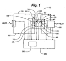
- FIG. 1 is a schematic diagram of a surge detection system according to a first embodiment of this invention.
- reference symbol 10 designates a basic refrigeration system.
- the refrigeration system 10 comprises a centrifugal compressor 20, having a suction side 25 and a discharge side 30 and a compressor impeller (not shown).
- a discharge side conduit 35 connects discharge side 30 to a condenser 40.
- the compressor compresses the refrigerant and delivers the compressed gas to condenser 40.
- Condenser 40 includes a heat-exchange coil 45 having an inlet 50 and an outlet 55 connected to a cooling tower 60 or other cooling system that circulates a cooling fluid, such as water, through the heat exchange coil 45.
- the refrigerant flowing through condenser 40 exchanges heat with the cooling fluid circulating through heat-exchange coil 45 causing the compressed gas to condense to a liquid refrigerant.
- An orifice 75 within the line to evaporator 70 causes a pressure drop that regulates the flow of refrigerant to the evaporator.
- Evaporator 70 includes a second heat-exchange coil 80 having a supply line 85 and a return line 90 connected to a cooling coil 95 and having a cooling fluid such as water circulating through heat-exchange coil 80.
- the cooling fluid exchanges heat with the liquid refrigerant causing it to vaporize thereby chilling the cooling fluid.
- Gaseous refrigerant from the evaporator returns to the compressor via a suction line 100.
- Reference symbol "A” in Fig. 1 exemplifies a location near the suction entrance 120 of evaporator 70 where a first temperature measurement 200 of the cooling fluid is taken. In an alternate embodiment, the first temperature measurement may be taken within return line 90.
- Reference symbol "B” in Fig. 2 exemplifies a location in suction side 25 that constitutes the entrance to the compressor impeller (not shown) where a second temperature measurement 210 of the refrigerant is taken. In another embodiment of the invention, second temperature measurement 210 may be measured within the compressor at a location proximate the impeller.
- Fig. 2 depicts the relative positions of reference marks "A" and "B" where temperature measurements are taken according to one exemplary embodiment of the invention.
- a typical refrigeration system includes many other features that are not shown in Figs. 1 and 2 . Those features not shown are not necessary to describe the present invention.
- an exemplary embodiment of the present invention utilizes temperature sensors placed in proximity to reference marks "A" and "B," as shown in Figs. 1 and 2 .
- the temperature sensors may generate a signal whose value is indicative of the measured temperature.
- the signal may be a voltage proportional to the measured temperature.
- a suction temperature sensor 220 measures a value indicative of the second temperature measurement 210 proximate the compressor, for example, at the entrance to the compressor impeller (reference mark "B").
- An evaporator water temperature sensor 225 measures a value indicative of the first temperature value 200 proximate the evaporator, for example, at the entrance of the water line into the evaporator (reference mark "A").
- the suction temperature 210 should not deviate from the evaporator water temperature 200. If the compressor undergoes a surge condition, it will add thermal energy in the form of heat to the refrigerant gas flowing into the compressor causing second temperature measurement 210 to rise.
- Another aspect of the invention includes means for monitoring the differential between the two sensors (located at "A" and "B,” respectively) through any of the several means known in the art for monitoring and controlling the operation of refrigeration systems.
- Yet another aspect of the present invention is to determine if the differential sensed by the suction temperature sensor 220 and the evaporator water temperature sensor 225 exceeds a set point parameter indicative of an operating condition of the compressor.
- the set point parameter will vary with the operating condition of centrifugal compressor 20.
- the first operating condition is when the compressor is in the "off" state or non-operational. This operating condition is referred to as an off-state condition.
- the means for comparing the temperature differential will automatically signal no surge fault.
- the second operating condition is when the compressor is in a "starting" state.
- This state is unique since the suction temperature sensor 220 located in the compressor case may be warmed excessively by the gear case heaters and surrounding ambient temperatures.
- the evaporator water temperature Prior to starting the compressor 20, the evaporator water temperature may be held low by other chillers in the refrigeration system 10. Therefore, if the suction temperature is greater than entering evaporator water temperature, the surge detection system will protect the system by detecting surge when there is an increase in temperature with time during startup. If the suction temperature is rising faster than the water temperature, the surge detection system will create a surge fault to shut down the compressor. When the suction temperature falls below some fraction of the set point that will cause a surge fault during normal running conditions, then the surge detection system switches to normal surge fault protection as described below.
- the third operating condition encountered by the surge detection system is during normal running of the compressor.
- a surge fault is registered and the compressor is shut down if, while the compressor is running, the difference between the suction temperature and the evaporator water temperature exceeds a set point.
- Fig. 3 is a chart showing an exemplary set of temperature measurements at reference points "A" and "B" in accordance with one embodiment of the present invention.
- the refrigeration system of a preferred embodiment of the present invention further includes a chiller control panel 280 having a main microprocessor 290.
- microprocessor 290 receives signals representative of suction temperatures and evaporator water temperatures from suction temperature sensor 220 and evaporator water temperature sensor 225 respectively.
- the temperature differential between the temperatures at the two locations may instead be measured by using a suitable sensor.
- the temperature signals may be acquired continuously or periodically.
- Microprocessor 290 also implements routines that detect changes in the operational condition of the centrifugal compressor and computes a set point corresponding to the detected operational condition. In one embodiment, the deviation of the temperature differential from the set point is representative of a surge condition. Desirably, on detecting surge, the microprocessor 290 generates control signals to adjust the operation of the refrigerant system.
Landscapes
- Engineering & Computer Science (AREA)
- Mechanical Engineering (AREA)
- General Engineering & Computer Science (AREA)
- Physics & Mathematics (AREA)
- Thermal Sciences (AREA)
- Control Of Positive-Displacement Air Blowers (AREA)
- Structures Of Non-Positive Displacement Pumps (AREA)
- Control Of Non-Positive-Displacement Pumps (AREA)
- Control Of Positive-Displacement Pumps (AREA)
Description
- The present invention generally relates to chiller systems. More specifically, the present invention relates to methods for detecting surge in a centrifugal compressor integral to a refrigeration system.
- Surging is an unstable operating condition that occurs in compressors, including centrifugal compressors used in refrigeration systems. Such a condition can be caused by an increase or decrease in compressor discharge pressure or by a reduction in the flow of gas to the compressor. These events can be triggered by poor maintenance of the refrigeration system, failure of a system component, or human error. Excessive surging, either in number of occurrences or in magnitude, may result in damage or complete failure of the compressor. Surging also results in inefficiencies in operation of a refrigeration system that result in excessive power consumption.
- Extreme surging may be detectable by inspection of an operating compressor, by those knowledgeable in the art, but a compressor can operate in a surge condition with little vibration experienced. Different methods of detecting surge conditions in centrifugal compressors are known in the art. One method of detecting surge in a compressor is to monitor vibration of the compressor by mounting a vibration detector on or near the compressor to sense vibration caused by the compressor in a surged condition. Shortcomings of this method include the need for an extremely sensitive vibration sensor and false surge indications during start-up of the compressor.
- Another method of detecting surge is by monitoring flow and pressure differences in the vicinity of the compressor as disclosed in
U. S. Patent No. 3,555, 844 , An alternative means of detecting surge is disclosed inU. S. Patent No.2,696, 345 , which teaches monitoring temperature upstream of the impeller to detect an increase in temperature that precedes major surging. That same patent discloses a method of detecting surge by monitoring temperature on the discharge side of an axial flow compressor. However, as noted inU. S. Patent No. 4,363, 596 , monitoring temperature in the discharge is not effective in a refrigerant compressor because the discharge temperature of such a compressor will actually go down when the compressor is in surge, since the flow to the discharge is basically stopped. -
U. S. Patent No. 4,363, 596 teaches a method of detecting surge by measuring a temperature rise beyond a predetermined value in a space in the impeller chamber of the compressor, exterior of the flow path of gas through the impeller. The specification states that the temperature rise, above the normal operating temperature, occurring when the compressor is surging is caused by the increased heat produced by reduced compressor efficiency and the inability of the reduced gas flow to remove the heat. The disadvantage of this approach is that it measures the temperature rise in one location inside the impeller chamber and does not take into account that the temperature at the location may change due to a change in the operation condition of the compressor even when there is no surge. For example, a start-up condition is likely to give a false surge reading. - In the system disclosed in
U. S. Patent No. 4,151, 725 , a control system effectively maximizes efficiency without encountering surge problems by monitoring the temperature of the refrigerant in the condenser discharge line, the temperature of the saturated refrigerant leaving the evaporator, the temperature of the chilled water discharged from the evaporator of the chiller, and the inlet guide vane position. Based on the foregoing four parameters and a set point temperature input, the control system described inU. S. Patent No. 4,151, 725 effectively regulates the refrigeration system by regulating the speed of the compressor and adjusting vane position. A person skilled in the art will recognize that the temperatures being measured are unlikely to be influenced by incipient surge. -
U. S. Patent No. 5,746, 062 discloses the method of detecting surges in a centrifugal compressor via sensing suction and discharge pressures of the compressor. The same patent also discloses surge detection through monitoring of the current applied to the variable speed motor drive that drives the compressor. It will be readily apparent to one skilled in the art that a sudden change in the load on the system, not necessarily related to surge, could also influence the current applied to the motor thus increasing the likelihood of a false positive detection of surge. This patent also teaches utilizing both pressure sensing and current sensing techniques to detect a surge. - The existing methods for detecting surges in centrifugal compressors integral to refrigeration systems are concentrated on monitoring conditions in the proximity of the compressor. One of the disadvantages of such systems is that they can generate a high number of false positive readings on account of their being influenced by localized, transient effects that generally may not be indicative of surge.
- The present invention incorporates the use of operating conditions beyond the immediate vicinity of a centrifugal compressor of a refrigeration system to provide an accurate method of detecting surge in the compressor. One aspect of the present invention utilizes sensors to monitor the temperature differential between the suction temperature at the entrance to the compressor impeller and the evaporator water temperature. Another aspect of the invention compares the temperature differential between the suction temperature and evaporator water temperature to data points that correspond to the various operating conditions of the refrigeration system. By utilizing a more expansive set of operating conditions of the total refrigeration system in making a determination of whether a surge condition exists, the present invention reduces the influence of systemic transient conditions.
-
-
Fig. 1 is a schematic diagram of a surge detection system according to a first embodiment of this invention. -
Fig. 2 is a more detailed schematic diagram of a surge detection system ofFig. 1 . -
Fig. 3 is a chart showing an exemplary set of temperature measurements utilized in accordance with the present invention. - The present invention pertains to a method and apparatus for detecting surge in a compressor of a compressor-driven system. A compressor-driven refrigeration system is an example of such a system.
Fig. 1 is a schematic diagram of a surge detection system according to a first embodiment of this invention. InFig. 1 ,reference symbol 10 designates a basic refrigeration system. As shown inFig. 1 , therefrigeration system 10 comprises acentrifugal compressor 20, having asuction side 25 and adischarge side 30 and a compressor impeller (not shown). Adischarge side conduit 35 connectsdischarge side 30 to a condenser 40. The compressor compresses the refrigerant and delivers the compressed gas to condenser 40. Condenser 40 includes a heat-exchange coil 45 having aninlet 50 and anoutlet 55 connected to acooling tower 60 or other cooling system that circulates a cooling fluid, such as water, through theheat exchange coil 45. The refrigerant flowing through condenser 40 exchanges heat with the cooling fluid circulating through heat-exchange coil 45 causing the compressed gas to condense to a liquid refrigerant. - Condensed liquid refrigerant from the condenser 40 flows to an
evaporator 70. Anorifice 75 within the line toevaporator 70 causes a pressure drop that regulates the flow of refrigerant to the evaporator. Evaporator 70 includes a second heat-exchange coil 80 having asupply line 85 and areturn line 90 connected to acooling coil 95 and having a cooling fluid such as water circulating through heat-exchange coil 80. As the liquid refrigerant flows throughevaporator 70, the cooling fluid exchanges heat with the liquid refrigerant causing it to vaporize thereby chilling the cooling fluid. Gaseous refrigerant from the evaporator returns to the compressor via asuction line 100. - Reference symbol "A" in
Fig. 1 exemplifies a location near thesuction entrance 120 ofevaporator 70 where a first temperature measurement 200 of the cooling fluid is taken. In an alternate embodiment, the first temperature measurement may be taken withinreturn line 90. Reference symbol "B" inFig. 2 exemplifies a location insuction side 25 that constitutes the entrance to the compressor impeller (not shown) where a second temperature measurement 210 of the refrigerant is taken. In another embodiment of the invention, second temperature measurement 210 may be measured within the compressor at a location proximate the impeller. -
Fig. 2 depicts the relative positions of reference marks "A" and "B" where temperature measurements are taken according to one exemplary embodiment of the invention. A typical refrigeration system includes many other features that are not shown inFigs. 1 and2 . Those features not shown are not necessary to describe the present invention. - In operation, an exemplary embodiment of the present invention utilizes temperature sensors placed in proximity to reference marks "A" and "B," as shown in
Figs. 1 and2 . The temperature sensors may generate a signal whose value is indicative of the measured temperature. For example, the signal may be a voltage proportional to the measured temperature. Asuction temperature sensor 220 measures a value indicative of the second temperature measurement 210 proximate the compressor, for example, at the entrance to the compressor impeller (reference mark "B"). An evaporatorwater temperature sensor 225 measures a value indicative of the first temperature value 200 proximate the evaporator, for example, at the entrance of the water line into the evaporator (reference mark "A"). Under normal operating conditions where surging is not present, the suction temperature 210 should not deviate from the evaporator water temperature 200. If the compressor undergoes a surge condition, it will add thermal energy in the form of heat to the refrigerant gas flowing into the compressor causing second temperature measurement 210 to rise. Another aspect of the invention includes means for monitoring the differential between the two sensors (located at "A" and "B," respectively) through any of the several means known in the art for monitoring and controlling the operation of refrigeration systems. - Yet another aspect of the present invention is to determine if the differential sensed by the
suction temperature sensor 220 and the evaporatorwater temperature sensor 225 exceeds a set point parameter indicative of an operating condition of the compressor. In operation, the set point parameter will vary with the operating condition ofcentrifugal compressor 20. The first operating condition is when the compressor is in the "off" state or non-operational. This operating condition is referred to as an off-state condition. When the compressor is not operating, the means for comparing the temperature differential will automatically signal no surge fault. - The second operating condition is when the compressor is in a "starting" state. This state is unique since the
suction temperature sensor 220 located in the compressor case may be warmed excessively by the gear case heaters and surrounding ambient temperatures. Prior to starting thecompressor 20, the evaporator water temperature may be held low by other chillers in therefrigeration system 10. Therefore, if the suction temperature is greater than entering evaporator water temperature, the surge detection system will protect the system by detecting surge when there is an increase in temperature with time during startup. If the suction temperature is rising faster than the water temperature, the surge detection system will create a surge fault to shut down the compressor. When the suction temperature falls below some fraction of the set point that will cause a surge fault during normal running conditions, then the surge detection system switches to normal surge fault protection as described below. - The third operating condition encountered by the surge detection system is during normal running of the compressor. A surge fault is registered and the compressor is shut down if, while the compressor is running, the difference between the suction temperature and the evaporator water temperature exceeds a set point.
-
Fig. 3 is a chart showing an exemplary set of temperature measurements at reference points "A" and "B" in accordance with one embodiment of the present invention. - The refrigeration system of a preferred embodiment of the present invention further includes a
chiller control panel 280 having amain microprocessor 290. It will be evident to one skilled in the art that analog circuitry, a digital processor, software, firmware or any combination thereof may be used in place of themicroprocessor board 290. In an exemplary embodiment,microprocessor 290, receives signals representative of suction temperatures and evaporator water temperatures fromsuction temperature sensor 220 and evaporatorwater temperature sensor 225 respectively. It will be evident to one skilled in the art that instead of using two sensors to measure the temperatures at each of the two locations, the temperature differential between the temperatures at the two locations may instead be measured by using a suitable sensor. Furthermore, the temperature signals may be acquired continuously or periodically.Microprocessor 290 also implements routines that detect changes in the operational condition of the centrifugal compressor and computes a set point corresponding to the detected operational condition. In one embodiment, the deviation of the temperature differential from the set point is representative of a surge condition. Desirably, on detecting surge, themicroprocessor 290 generates control signals to adjust the operation of the refrigerant system. - While the invention has been described with reference to a preferred embodiment as disclosed above, it is to be clearly understood by those skilled in the art that the invention is not limited thereto.
Claims (9)
- A method for detecting surge in a refrigeration system (10), said refrigeration system including a centrifugal compressor (20) having an impeller and a compressor entrance, an evaporator (70) that receives a fluid refrigerant, a suction line that flows said refrigerant from said evaporator to said compressor entrance, said evaporator including a heat-exchange coil (80) supplied with a liquid through a supply line (85) entering said evaporator, said liquid disposed in a heat-exchange relationship with said refrigerant within said evaporator, the method comprising automatically and periodically performing the steps of :measuring a fluid temperature (200) of said liquid proximate said supply line entering said evaporator;measuring a refrigerant temperature (210) of said refrigerant proximate said compressor entrance; andusing said fluid temperature and said refrigerant temperature to detect surge in said refrigeration system.
- The method of claim 1, wherein the step of using said fluid temperature and said refrigerant temperature to detect surge comprises:computing a value indicative of a temperature difference between said fluid temperature and said refrigerant temperature; andcomparing said value to a set point temperature.
- The method of claim 1, wherein the step of using said fluid temperature and said refrigerant temperature to detect surge comprises:generating a compressor-status parameter indicative of an operating condition of said centrifugal compressor;deriving a set point parameter from said compressor-status parameter;computing a value indicative of a temperature difference between said fluid temperature and said refrigerant temperature; andcomparing said value to said set point parameter.
- The method of claim 3, wherein said operating condition of said centrifugal compressor is selected from a set consisting of: off-state, starting and normal running.
- An apparatus for detecting surge in a centrifugal compressor (20) in fluid communication with an evaporator (70) at a compressor entrance, said evaporator flowing a refrigerant fluid in heat-exchange relationship with a liquid entering said evaporator proximate a evaporator suction entrance, said apparatus comprising:means for detecting a first temperature (200) of said refrigerant proximate said compressor entrance;means for detecting a second temperature (210) of said liquid proximate said evaporator suction entrance;means for determining a differential between said first temperature and said second temperatures; andmeans for detecting surge by comparing said differential to a set point parameter.
- The apparatus of claim 5, wherein said means for detecting said first temperature is a temperature sensor (225).
- The apparatus of claim 6, wherein said means for detecting said second temperature is a temperature sensor (220).
- The apparatus of claim 5, wherein said means for determining said differential and said means for detecting surge are implemented as an operative arrangement selected from the set consisting of : analog circuitry, a digital processor, software, firmware or any combination thereof.
- The apparatus of claim 8, wherein said means for determining said differential controls an operation condition of said centrifugal compressor responsive to said differential.
Applications Claiming Priority (2)
| Application Number | Priority Date | Filing Date | Title |
|---|---|---|---|
| US46364403P | 2003-04-17 | 2003-04-17 | |
| PCT/US2004/012081 WO2004094925A2 (en) | 2003-04-17 | 2004-04-19 | Methods for detecting surge in centrifugal compressors |
Publications (4)
| Publication Number | Publication Date |
|---|---|
| EP1616135A2 EP1616135A2 (en) | 2006-01-18 |
| EP1616135A4 EP1616135A4 (en) | 2012-10-31 |
| EP1616135B1 true EP1616135B1 (en) | 2014-08-20 |
| EP1616135B8 EP1616135B8 (en) | 2015-03-11 |
Family
ID=33310802
Family Applications (1)
| Application Number | Title | Priority Date | Filing Date |
|---|---|---|---|
| EP04760017.6A Expired - Lifetime EP1616135B8 (en) | 2003-04-17 | 2004-04-19 | Methods for detecting surge in centrifugal compressors |
Country Status (7)
| Country | Link |
|---|---|
| US (1) | US7069734B2 (en) |
| EP (1) | EP1616135B8 (en) |
| JP (1) | JP4565282B2 (en) |
| CN (1) | CN100397000C (en) |
| CA (1) | CA2522760C (en) |
| MX (1) | MXPA05011194A (en) |
| WO (1) | WO2004094925A2 (en) |
Families Citing this family (11)
| Publication number | Priority date | Publication date | Assignee | Title |
|---|---|---|---|---|
| US20070095512A1 (en) * | 2005-10-31 | 2007-05-03 | Wei Chen | Shell and tube evaporator |
| US20070107886A1 (en) * | 2005-11-14 | 2007-05-17 | Wei Chen | Evaporator for a refrigeration system |
| GB0716329D0 (en) * | 2007-08-21 | 2007-10-03 | Compair Uk Ltd | Improvements in compressors control |
| NO333438B1 (en) | 2010-07-14 | 2013-06-03 | Statoil Asa | Method and apparatus for composition-based compressor control and performance monitoring. |
| EP2756240B1 (en) * | 2011-09-14 | 2019-05-01 | Danfoss A/S | Centrifugal compressor diffuser control |
| US10544791B2 (en) | 2011-12-01 | 2020-01-28 | Carrier Corporation | Centrifugal compressor startup control |
| CN102635565B (en) * | 2012-03-30 | 2014-10-15 | 西安陕鼓动力股份有限公司 | Method for dynamically biasing anti-surge curve of turbine compressor |
| CN102588315B (en) * | 2012-03-30 | 2014-10-15 | 西安陕鼓动力股份有限公司 | Automatic surge testing method for turbine compressor |
| CN106124078B (en) * | 2016-07-25 | 2019-02-22 | 北京航空航天大学 | A method for measuring the temperature of strongly transient fluids using dual thermocouples |
| CN109595149A (en) * | 2019-01-15 | 2019-04-09 | 上海汽车集团股份有限公司 | The automatic identifying method and system of engine supercharger surge |
| US12163711B2 (en) | 2021-06-25 | 2024-12-10 | Carrier Corporation | Surge prevention in a chiller with centrifugal compressor |
Family Cites Families (27)
| Publication number | Priority date | Publication date | Assignee | Title |
|---|---|---|---|---|
| US2696345A (en) | 1949-10-14 | 1954-12-07 | United Aircraft Corp | Method of controlling supercharger to avoid pulsation |
| US3555844A (en) | 1969-01-02 | 1971-01-19 | Borg Warner | Anti-surge compressor capacity control |
| USRE30329E (en) | 1975-12-01 | 1980-07-08 | Compressor Controls Corp. | Method and apparatus for antisurge protection of a dynamic compressor |
| US4046490A (en) | 1975-12-01 | 1977-09-06 | Compressor Controls Corporation | Method and apparatus for antisurge protection of a dynamic compressor |
| US4151725A (en) | 1977-05-09 | 1979-05-01 | Borg-Warner Corporation | Control system for regulating large capacity rotating machinery |
| US4177649A (en) * | 1977-11-01 | 1979-12-11 | Borg-Warner Corporation | Surge suppression apparatus for compressor-driven system |
| US4363596A (en) | 1979-06-18 | 1982-12-14 | Mcquay-Perfex, Inc. | Method and apparatus for surge detection and control in centrifugal gas compressors |
| US4265589A (en) | 1979-06-18 | 1981-05-05 | Westinghouse Electric Corp. | Method and apparatus for surge detection and control in centrifugal gas compressors |
| US4282718A (en) | 1979-09-12 | 1981-08-11 | Borg-Warner Corporation | Evaporator inlet water temperature control system |
| US4464720A (en) | 1982-02-12 | 1984-08-07 | The Babcock & Wilcox Company | Centrifugal compressor surge control system |
| US4493608A (en) | 1982-12-27 | 1985-01-15 | General Electric Company | Surge control in compressor |
| US4562531A (en) * | 1983-10-07 | 1985-12-31 | The Babcock & Wilcox Company | Integrated control of output and surge for a dynamic compressor control system |
| US4546618A (en) * | 1984-09-20 | 1985-10-15 | Borg-Warner Corporation | Capacity control systems for inverter-driven centrifugal compressor based water chillers |
| US4581900A (en) | 1984-12-24 | 1986-04-15 | Borg-Warner Corporation | Method and apparatus for detecting surge in centrifugal compressors driven by electric motors |
| US4686834A (en) * | 1986-06-09 | 1987-08-18 | American Standard Inc. | Centrifugal compressor controller for minimizing power consumption while avoiding surge |
| US5306116A (en) | 1992-04-10 | 1994-04-26 | Ingersoll-Rand Company | Surge control and recovery for a centrifugal compressor |
| US5726891A (en) | 1994-01-26 | 1998-03-10 | Sisson; Patterson B. | Surge detection system using engine signature |
| US5537830A (en) | 1994-11-28 | 1996-07-23 | American Standard Inc. | Control method and appartus for a centrifugal chiller using a variable speed impeller motor drive |
| US5746062A (en) * | 1996-04-11 | 1998-05-05 | York International Corporation | Methods and apparatuses for detecting surge in centrifugal compressors |
| JP2001501694A (en) | 1996-05-22 | 2001-02-06 | インガーソル ランド カンパニー | Detection method of surge occurrence in centrifugal compressor |
| US5873257A (en) | 1996-08-01 | 1999-02-23 | Smart Power Systems, Inc. | System and method of preventing a surge condition in a vane-type compressor |
| US5845509A (en) * | 1997-09-26 | 1998-12-08 | Shaw; David N. | Variable speed parallel centrifugal compressors for HVAC and refrigeration systems |
| US6202431B1 (en) | 1999-01-15 | 2001-03-20 | York International Corporation | Adaptive hot gas bypass control for centrifugal chillers |
| US6513333B2 (en) | 2000-05-25 | 2003-02-04 | Honda Giken Kogyo Kabushiki Kaisha | Surge detection system of gas turbine aeroengine |
| CN2536821Y (en) * | 2001-12-06 | 2003-02-19 | 重庆通用工业(集团)有限责任公司 | Adjustable guide blade and diffuser linkage device for inlet of centrifugal refrigerating compressor |
| US6981838B2 (en) | 2002-02-26 | 2006-01-03 | Southern Gas Association Gas Machinery Reserach Council | Method and apparatus for detecting the occurrence of surge in a centrifugal compressor |
| US6910349B2 (en) | 2002-08-06 | 2005-06-28 | York International Corporation | Suction connection for dual centrifugal compressor refrigeration systems |
-
2004
- 2004-04-19 JP JP2006513135A patent/JP4565282B2/en not_active Expired - Fee Related
- 2004-04-19 US US10/827,109 patent/US7069734B2/en not_active Expired - Lifetime
- 2004-04-19 MX MXPA05011194A patent/MXPA05011194A/en active IP Right Grant
- 2004-04-19 WO PCT/US2004/012081 patent/WO2004094925A2/en not_active Ceased
- 2004-04-19 CA CA002522760A patent/CA2522760C/en not_active Expired - Fee Related
- 2004-04-19 CN CNB2004800158607A patent/CN100397000C/en not_active Expired - Fee Related
- 2004-04-19 EP EP04760017.6A patent/EP1616135B8/en not_active Expired - Lifetime
Also Published As
| Publication number | Publication date |
|---|---|
| WO2004094925A3 (en) | 2006-03-09 |
| CA2522760C (en) | 2009-09-22 |
| CN1826499A (en) | 2006-08-30 |
| US7069734B2 (en) | 2006-07-04 |
| JP4565282B2 (en) | 2010-10-20 |
| CA2522760A1 (en) | 2004-11-04 |
| US20040221592A1 (en) | 2004-11-11 |
| JP2006523805A (en) | 2006-10-19 |
| WO2004094925A2 (en) | 2004-11-04 |
| CN100397000C (en) | 2008-06-25 |
| EP1616135A2 (en) | 2006-01-18 |
| EP1616135B8 (en) | 2015-03-11 |
| EP1616135A4 (en) | 2012-10-31 |
| HK1092864A1 (en) | 2007-02-16 |
| MXPA05011194A (en) | 2006-03-09 |
Similar Documents
| Publication | Publication Date | Title |
|---|---|---|
| US4535598A (en) | Method and control system for verifying sensor operation in a refrigeration system | |
| EP1706684B1 (en) | Diagnosing a loss of refrigerant charge in a refrigerant system | |
| US6981384B2 (en) | Monitoring refrigerant charge | |
| KR100732573B1 (en) | Compressor protection from liquid hazards | |
| CA1111396A (en) | Method and apparatus for surge detection and control in centrifugal gas compressors | |
| EP0159281B1 (en) | High-low superheat protection for a refrigeration system compressor | |
| JP6396662B2 (en) | Refrigeration apparatus and control device for refrigerator | |
| KR900004461B1 (en) | Operation control system of refrigeration system and its control method | |
| US7069734B2 (en) | Methods for detecting surge in centrifugal compressors | |
| US4363596A (en) | Method and apparatus for surge detection and control in centrifugal gas compressors | |
| US20090274565A1 (en) | Continuing compressor operation through redundant algorithms | |
| CN101802521A (en) | Refrigeration monitoring system and method | |
| EP3446053B1 (en) | Refrigeration system control and protection device | |
| WO2006025880A1 (en) | System and method for detecting decreased performance in a refrigeration system | |
| WO2001092794A1 (en) | Refrigerant monitoring apparatus and method | |
| KR100378578B1 (en) | Method and apparatus for detecting surge from centrifugal compressor | |
| EP4513096B1 (en) | Heat pump system and method for controlling pump speed based on leakage detection data and water flow rate data | |
| HK1092864B (en) | A method and apparatus for detecting surge in a refrigeration system and a centrifugal compressor | |
| CN120083682B (en) | Compressor self-checking method, thermal management system and storage medium | |
| EP4664038A1 (en) | Fault detection of an expansion valve | |
| JP2005061352A (en) | Centrifugal compressor of turbo-refrigerator, turbo-refrigerator, and its control method | |
| JPH07117075B2 (en) | Surging detection device in turbo compressor |
Legal Events
| Date | Code | Title | Description |
|---|---|---|---|
| PUAI | Public reference made under article 153(3) epc to a published international application that has entered the european phase |
Free format text: ORIGINAL CODE: 0009012 |
|
| 17P | Request for examination filed |
Effective date: 20051028 |
|
| AK | Designated contracting states |
Kind code of ref document: A2 Designated state(s): AT BE BG CH CY CZ DE DK EE ES FI FR GB GR HU IE IT LI LU MC NL PL PT RO SE SI SK TR |
|
| AX | Request for extension of the european patent |
Extension state: AL HR LT LV MK |
|
| PUAK | Availability of information related to the publication of the international search report |
Free format text: ORIGINAL CODE: 0009015 |
|
| DAX | Request for extension of the european patent (deleted) | ||
| RBV | Designated contracting states (corrected) |
Designated state(s): DE FR GB IT |
|
| RIC1 | Information provided on ipc code assigned before grant |
Ipc: F25B 41/00 20060101AFI20060816BHEP |
|
| A4 | Supplementary search report drawn up and despatched |
Effective date: 20121004 |
|
| RIC1 | Information provided on ipc code assigned before grant |
Ipc: F25B 1/04 20060101ALI20120927BHEP Ipc: F04D 27/02 20060101AFI20120927BHEP |
|
| 17Q | First examination report despatched |
Effective date: 20130305 |
|
| REG | Reference to a national code |
Ref country code: DE Ref legal event code: R079 Ref document number: 602004045681 Country of ref document: DE Free format text: PREVIOUS MAIN CLASS: F25B0041000000 Ipc: F04D0027020000 |
|
| RIC1 | Information provided on ipc code assigned before grant |
Ipc: F25B 1/04 20060101ALI20130919BHEP Ipc: F04D 27/02 20060101AFI20130919BHEP Ipc: F04D 27/00 20060101ALI20130919BHEP |
|
| GRAP | Despatch of communication of intention to grant a patent |
Free format text: ORIGINAL CODE: EPIDOSNIGR1 |
|
| INTG | Intention to grant announced |
Effective date: 20140120 |
|
| GRAS | Grant fee paid |
Free format text: ORIGINAL CODE: EPIDOSNIGR3 |
|
| GRAA | (expected) grant |
Free format text: ORIGINAL CODE: 0009210 |
|
| AK | Designated contracting states |
Kind code of ref document: B1 Designated state(s): DE FR GB IT |
|
| REG | Reference to a national code |
Ref country code: GB Ref legal event code: FG4D |
|
| REG | Reference to a national code |
Ref country code: DE Ref legal event code: R096 Ref document number: 602004045681 Country of ref document: DE Effective date: 20141002 |
|
| RAP2 | Party data changed (patent owner data changed or rights of a patent transferred) |
Owner name: DAIKIN APPLIED AMERICAS INC. |
|
| REG | Reference to a national code |
Ref country code: FR Ref legal event code: CD Owner name: DAIKIN APPLIED AMERICAS INC., US Effective date: 20150106 |
|
| REG | Reference to a national code |
Ref country code: DE Ref legal event code: R081 Ref document number: 602004045681 Country of ref document: DE Owner name: DAIKIN APPLIED AMERICAS INC., MINNEAPOLIS, US Free format text: FORMER OWNER: AAF-MCQUAY INC., MINNEAPOLIS, MINN., US Effective date: 20150126 Ref country code: DE Ref legal event code: R081 Ref document number: 602004045681 Country of ref document: DE Owner name: DAIKIN APPLIED AMERICAS INC., MINNEAPOLIS, US Free format text: FORMER OWNER: AAF-MCQUAY INC., MINNEAPOLIS, MINN., US Effective date: 20140821 |
|
| REG | Reference to a national code |
Ref country code: DE Ref legal event code: R097 Ref document number: 602004045681 Country of ref document: DE |
|
| PLBE | No opposition filed within time limit |
Free format text: ORIGINAL CODE: 0009261 |
|
| STAA | Information on the status of an ep patent application or granted ep patent |
Free format text: STATUS: NO OPPOSITION FILED WITHIN TIME LIMIT |
|
| 26N | No opposition filed |
Effective date: 20150521 |
|
| REG | Reference to a national code |
Ref country code: DE Ref legal event code: R119 Ref document number: 602004045681 Country of ref document: DE |
|
| GBPC | Gb: european patent ceased through non-payment of renewal fee |
Effective date: 20150419 |
|
| PG25 | Lapsed in a contracting state [announced via postgrant information from national office to epo] |
Ref country code: IT Free format text: LAPSE BECAUSE OF NON-PAYMENT OF DUE FEES Effective date: 20150419 Ref country code: GB Free format text: LAPSE BECAUSE OF NON-PAYMENT OF DUE FEES Effective date: 20150419 Ref country code: DE Free format text: LAPSE BECAUSE OF NON-PAYMENT OF DUE FEES Effective date: 20151103 |
|
| REG | Reference to a national code |
Ref country code: FR Ref legal event code: ST Effective date: 20151231 |
|
| PG25 | Lapsed in a contracting state [announced via postgrant information from national office to epo] |
Ref country code: FR Free format text: LAPSE BECAUSE OF NON-PAYMENT OF DUE FEES Effective date: 20150430 |