EP1615294A1 - Ultra wide band antenna - Google Patents
Ultra wide band antenna Download PDFInfo
- Publication number
- EP1615294A1 EP1615294A1 EP04291700A EP04291700A EP1615294A1 EP 1615294 A1 EP1615294 A1 EP 1615294A1 EP 04291700 A EP04291700 A EP 04291700A EP 04291700 A EP04291700 A EP 04291700A EP 1615294 A1 EP1615294 A1 EP 1615294A1
- Authority
- EP
- European Patent Office
- Prior art keywords
- main conductor
- uwb
- uwb antenna
- antenna according
- attachment
- Prior art date
- Legal status (The legal status is an assumption and is not a legal conclusion. Google has not performed a legal analysis and makes no representation as to the accuracy of the status listed.)
- Withdrawn
Links
- 239000004020 conductor Substances 0.000 claims abstract description 54
- 238000000034 method Methods 0.000 claims description 5
- 238000004891 communication Methods 0.000 claims description 4
- 238000004519 manufacturing process Methods 0.000 claims description 3
- 239000000463 material Substances 0.000 claims description 2
- 239000007787 solid Substances 0.000 claims description 2
- 230000007704 transition Effects 0.000 claims description 2
- 238000010586 diagram Methods 0.000 description 6
- 230000000694 effects Effects 0.000 description 6
- 238000001914 filtration Methods 0.000 description 3
- 230000009286 beneficial effect Effects 0.000 description 2
- 230000003071 parasitic effect Effects 0.000 description 2
- 238000004458 analytical method Methods 0.000 description 1
- 230000005540 biological transmission Effects 0.000 description 1
- 230000008859 change Effects 0.000 description 1
- 230000001419 dependent effect Effects 0.000 description 1
- 238000005516 engineering process Methods 0.000 description 1
- 235000015243 ice cream Nutrition 0.000 description 1
- 238000007373 indentation Methods 0.000 description 1
- 230000004048 modification Effects 0.000 description 1
- 238000012986 modification Methods 0.000 description 1
- 230000005855 radiation Effects 0.000 description 1
- 239000000758 substrate Substances 0.000 description 1
Images




Classifications
-
- H—ELECTRICITY
- H01—ELECTRIC ELEMENTS
- H01Q—ANTENNAS, i.e. RADIO AERIALS
- H01Q9/00—Electrically-short antennas having dimensions not more than twice the operating wavelength and consisting of conductive active radiating elements
- H01Q9/04—Resonant antennas
- H01Q9/16—Resonant antennas with feed intermediate between the extremities of the antenna, e.g. centre-fed dipole
- H01Q9/28—Conical, cylindrical, cage, strip, gauze, or like elements having an extended radiating surface; Elements comprising two conical surfaces having collinear axes and adjacent apices and fed by two-conductor transmission lines
-
- H—ELECTRICITY
- H01—ELECTRIC ELEMENTS
- H01Q—ANTENNAS, i.e. RADIO AERIALS
- H01Q9/00—Electrically-short antennas having dimensions not more than twice the operating wavelength and consisting of conductive active radiating elements
- H01Q9/04—Resonant antennas
- H01Q9/30—Resonant antennas with feed to end of elongated active element, e.g. unipole
- H01Q9/40—Element having extended radiating surface
Definitions
- the invention relates to ultra wide band antennas. In particular, but not exclusively, it relates to the form of the ultra wide band antenna.
- UWB ultra wide band
- FCC Federal Communication Commission
- CEPT European Conference of Postal and Telecommunications Administrations
- UWB technologies are expected to play an important role in the future for a wide variety of short-range high data-rate applications. This includes traditional wireless such as Local Area Networks (LAN), Personal Area Networks (PAN) and Body Area Networks (BAN), as well as consumer electronic devices (such as in photo and video cameras, set-top boxes, modem-routers, etc.) that increasingly have the need to communicate.
- LAN Local Area Networks
- PAN Personal Area Networks
- BAN Body Area Networks
- consumer electronic devices such as in photo and video cameras, set-top boxes, modem-routers, etc.
- a further application of UWB is long-range asset tracking, where the positioning information that can be obtained very accurately in UWB systems is employed.
- antenna design must deal with several constraints simultaneously: bandwidth, gain (related to impedance matching), phase, efficiency, directivity, size and cost.
- the antenna can be treated as a simple load with a certain impedance. This in turn creates the implicit assumption that the basic performance of the antenna is fixed over the bandwidth of the narrow-band signal.
- known UWB antennas in the art include patch antennas 101, horn antennas 102, and conical antennas 103.
- the name is derived from the nature of the main conductor, i.e. the radiating /receiving component illustrated.
- Patch antennas are better characterised as multi-band rather than wide-band antennas, due to the successive resonances of the substrate, while horn antennas are bulky and highly directive.
- Conical antennas are theoretically ideal given an infinite cone, which provides an infinite bandwidth and a stable gain with respect to frequency (thanks to a matching condition independent of the frequency). Furthermore, the radiated field pattern, close to the one provided by a dipole antenna, is also independent of the frequency and is well suited to illuminate a room.
- the main conductor cone must of course be truncated; this causes the currents on the outer surface of the cone to be reflected.
- the result of this reflected current provides a good impedance to the bi-cone antenna can only be ensured for approximately a 50% bandwidth relative to central frequency (e.g. 1 to 2GHz).
- a related structure is the mono-conical antenna 201, comprising the main conductor 210, a ground plate 220 and a connector 230.
- the ground plate which reflects to act as a virtual dipole. This reduces the height of the antenna.
- the ground plane provides symmetry in the electrical (E) field and antisymmetry in the magnetic (H) field. Ideally the ground plane is infinite, but in practice it is sufficient to only extend a couple of the wavelengths.
- this structure does not fully attenuate current reflection and leads to a bulky antenna, needing additional pieces to maintain the main conductor. Consequently it was structurally weak.
- the purpose of the present invention is to address the above need.
- the present invention provides an ultra wide band (UWB) antenna, characterised by a teardrop shaped main conductor, wherein beyond a region of attachment, a first derivative of the profile of the main conductor is continuous.
- UWB ultra wide band
- the present invention provides an ultra wide band antenna, as claimed in claim 1.
- the present invention provides a communication device, as claimed in claim 13.
- the present invention provides a method of manufacture, as claimed in claim 14.
- the present invention provides a method of transmission or reception, as claimed in claim 15.
- UWB ultra wide band
- a main conductor wherein the first derivative of the surface profile is a continuous function is beneficial.
- Such a profile achieves an adiabatic transition over a continuum of angles that significantly reduces the problem of current reflection, so improving the amount of utilisable bandwidth from the antenna.
- an ultra wide band (UWB) antenna is characterised by a teardrop shaped main conductor 400, wherein beyond a region of attachment 502, a first derivative of the profile of the main conductor is continuous, i.e. has no discontinuity.
- the resulting profile 501 is not concave (i.e convex) over the length of the longitudinal axis of the main conductor.
- equation (3) is a polynomial, the roots can easily be found.
- N need not necessarily be an integer.
- the angle of tangent adjacent to the region of attachment may reasonably expect the angle of tangent adjacent to the region of attachment to vary according to specification, but typically be substantially between 40° and 50° to the longitudinal axis of the teardrop and to the ground plate.
- an impedance between 45 and 55 ⁇ may be typical.
- the gradient at the top of the main conductor would equal 0 when x > 0, and so a flat top from radius 0 to x becomes possible whilst still having a continuous first derivative.
- the curvature of the profile 501 may be flat at any point as long as it joins at the tangent of the remaining curve. However, it is believed that such an arrangement would be sub-optimal in terms of gain uniformity.
- manufacture of a teardrop shaped main conductor as described herein may be achieved by feeding the profile 501 into a programmable lathe or similar to generate a solid of rotation.
- ground plate 610 is provided.
- the ground plate 610 has two functions that influence its dimensions:
- the connector 710 (typically a 'Subminiature Version A' or SMA connector as known in the art) preferably has a dielectric constant in its coaxial material to substantially match the impedance of the main conductor 400.
- a pin or similar protrusion (not shown) extending from the region of attachment of the teardrop shaped main conductor 400 is suitable to plug into the central conductor of an SMA connector 710.
- the pin passes though a ring 620 of plastic, preferably rexolyte, which has been inserted within the ground plate 610.
- the ring 620 and ground plate 610 are arranged such that the ring 620 cannot pass through the ground plate 610, for example by having a protruding lip on the ring 620 and corresponding indentation in the ground plate 610, as shown in figure 6.
- the pin of the teardrop shaped main conductor 400 fits firmly but removably into the ring 620 and SMA connector 710.
- ⁇ r 2.53 - the sizes of the ground plate and the inside of the ring are chosen to provide a coaxial wave-guide that substantially matches the impedance of the main conductor 400.
Landscapes
- Waveguide Aerials (AREA)
Abstract
Description
- The invention relates to ultra wide band antennas. In particular, but not exclusively, it relates to the form of the ultra wide band antenna.
- An ultra wide band (UWB) system is any radio system where the bandwidth of the desired signal is either greater than 20% of the centre frequency or greater than 500MHz. In 2002 the US Federal Communication Commission (FCC) made available the 3.1 to 10.6GHz band to radio communication meeting this definition of UWB, operating in indoor or hand-held peer-to-peer configurations. In Europe, the European Conference of Postal and Telecommunications Administrations (CEPT) is currently evolving towards a regulation that is similar to that proposed by the FCC.
- UWB technologies are expected to play an important role in the future for a wide variety of short-range high data-rate applications. This includes traditional wireless such as Local Area Networks (LAN), Personal Area Networks (PAN) and Body Area Networks (BAN), as well as consumer electronic devices (such as in photo and video cameras, set-top boxes, modem-routers, etc.) that increasingly have the need to communicate. A further application of UWB is long-range asset tracking, where the positioning information that can be obtained very accurately in UWB systems is employed.
- The extreme bandwidth requirement of UWB systems places stringent design constraints on the antenna that is used. The design of a "good" antenna is important to preserve the pulse shapes utilized within UWB, and the antennas should present a good impedance match and a monotonic phase over the whole frequency range used by the system.
- Accordingly, antenna design must deal with several constraints simultaneously: bandwidth, gain (related to impedance matching), phase, efficiency, directivity, size and cost.
- In most narrow-band radio design, it is assumed that the antenna can be treated as a simple load with a certain impedance. This in turn creates the implicit assumption that the basic performance of the antenna is fixed over the bandwidth of the narrow-band signal.
- However, when designing an antenna for a UWB system the antenna performance will not be fixed over the bandwidth. This will have a filtering effect on the transmitted pulses that will significantly change their form with transmit frequency. In addition to this frequency filtering effect, there is also a spatial filtering effect, as the radiation pattern of wide-band antennas is not constant with frequency.
- Referring now to Figure 1, known UWB antennas in the art include
patch antennas 101,horn antennas 102, andconical antennas 103. In each case, the name is derived from the nature of the main conductor, i.e. the radiating /receiving component illustrated. - Patch antennas are better characterised as multi-band rather than wide-band antennas, due to the successive resonances of the substrate, while horn antennas are bulky and highly directive.
- Conical antennas are theoretically ideal given an infinite cone, which provides an infinite bandwidth and a stable gain with respect to frequency (thanks to a matching condition independent of the frequency). Furthermore, the radiated field pattern, close to the one provided by a dipole antenna, is also independent of the frequency and is well suited to illuminate a room.
- In practice, however, the main conductor cone must of course be truncated; this causes the currents on the outer surface of the cone to be reflected. The result of this reflected current provides a good impedance to the bi-cone antenna can only be ensured for approximately a 50% bandwidth relative to central frequency (e.g. 1 to 2GHz).
- Referring now to Figure 2, a related structure is the mono-
conical antenna 201, comprising themain conductor 210, aground plate 220 and aconnector 230. In this case, one of the truncated cones is replaced with the ground plate, which reflects to act as a virtual dipole. This reduces the height of the antenna. Typically the ground plane provides symmetry in the electrical (E) field and antisymmetry in the magnetic (H) field. Ideally the ground plane is infinite, but in practice it is sufficient to only extend a couple of the wavelengths. - Such antennas have been largely studied from a theoretical point of view (e.g. see C.A. Balanis, "Antenna theory - analysis and design", Harper and Row, New York, 1982, Chapt. 8, pp.322-371). Several authors point out in particular the effect of the shape in the vicinity of the ground plate on the equivalent parasitic lumped elements, and the effect of the main conductor shape on the radiated far field (e.g. see M. Piette et al., "High frequency effect of the junction between cone tip, coaxial feeder and ground plane on the input impedance of a long monocone antenna on ground plane", Antennas and Propagation, ICAP '95. Ninth International Conference on, No 407, pp.465-469, April 1995).
- From a practical perspective, such antennas have to date found application mainly in omni-directional and ultra-wideband contexts. Lu et al. have described such antennas in a VHF context (see M. Lu et al., "A high quality ultra wideband omni-direction antenna", Electromagnetic Compatibility Proceedings, International Symposium on , pp. 122 -125, May 1997).
- Referring to figure 3, Taniguchi et al. in "An omnidirectional and low VSWR antenna for UWB wireless systems", Radio and Wireless Conference RAWCON, pp. 145-148, August 2002, recently described modifying the cone form by adding a hemisphere to a conical UWB antenna, resulting in an 'ice cream cone'
structure 301, to attenuate the parasitic effect on the far field. However, among other things this structure does not fully attenuate current reflection and leads to a bulky antenna, needing additional pieces to maintain the main conductor. Consequently it was structurally weak. - Thus, a need exists for a mechanically robust UWB antenna that is compact whilst providing sufficient bandwidth, impedance and gain performance.
- The purpose of the present invention is to address the above need.
- The present invention provides an ultra wide band (UWB) antenna, characterised by a teardrop shaped main conductor, wherein beyond a region of attachment, a first derivative of the profile of the main conductor is continuous.
- In a first aspect, the present invention provides an ultra wide band antenna, as claimed in
claim 1. - In a second aspect, the present invention provides a communication device, as claimed in claim 13.
- In a third aspect the present invention provides a method of manufacture, as claimed in claim 14.
- In a fourth aspect the present invention provides a method of transmission or reception, as claimed in
claim 15. - Further features of the present invention are as defined in the dependent claims.
-
- FIG. 1 is a schematic diagram illustrating forms of antenna main conductors known in the art.
- FIG. 2 is a schematic diagram illustrating a further form of antenna main conductor known in the art.
- FIG. 3 is a schematic diagram illustrating a yet further form of antenna main conductor known in the art.
- Embodiments of the present invention will now be described by way of example with reference to the accompanying drawings, in which:
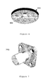
- FIG. 4 is a mesh illustrating of the form of an antenna main conductor shape in accordance with an embodiment of the present invention.
- FIG. 5 is a graph illustrating a curve of an antenna main conductor profile as a function of x and y in accordance with an embodiment of the present invention.
- FIG. 6 is a schematic diagram illustrating a ground plate in accordance with an embodiment of the present invention.
- FIG. 7 is a schematic diagram illustrating a connector in accordance with an embodiment of the present invention.
- FIG. 8 is a schematic diagram illustrating an assembly of a main conductor, ground plate an connector in accordance with an embodiment of the present invention.
- FIG. 9 is a graph illustrating amplitude (modulo) and phase versus frequency for an S11 parameter for an antenna in accordance with the present invention.
- FIG. 10 depicts graphs in spherical coordinates illustrating angular coverage over separate frequencies for an antenna in accordance with the present invention.
- An ultra wide band (UWB) antenna is disclosed. In the following description, a number of specific details are presented in order to provide a thorough understanding of an embodiment of the present invention. It will be apparent, however, to a person skilled in the art that these specific details need not be employed to practice the present invention. In other instances, well known methods, procedures and components have not been described in detail in order to avoid unnecessarily obscuring the present invention.
- The inventors of the present invention have appreciated that an alternative to the conical form of antenna main conductor may be beneficial.
- Specifically, they have appreciated that a main conductor wherein the first derivative of the surface profile is a continuous function is beneficial. Such a profile achieves an adiabatic transition over a continuum of angles that significantly reduces the problem of current reflection, so improving the amount of utilisable bandwidth from the antenna.
- Referring now to Figures 4 and 5, in a preferred embodiment of the invention an ultra wide band (UWB) antenna is characterised by a teardrop shaped
main conductor 400, wherein beyond a region ofattachment 502, a first derivative of the profile of the main conductor is continuous, i.e. has no discontinuity. - In an embodiment of the present invention, the curve of the
teardrop profile 501 is derived using a parametric curve comprising:
- The resulting
profile 501 is not concave (i.e convex) over the length of the longitudinal axis of the main conductor. - In practice, the curve will be truncated at one end to meet the coaxial field of a connector. Consequently one needs to find a value of t such that at a region of attachment of the main conductor, radius x equals the radius of the field connector, R F (identified as
point 502 in Figure 5). - Defining x in terms of v=sin(t/2), equation (1) can then be re-written as:

- Thus, defining u = v 2 , searching x = R F is equivalent to seek the roots of the following equation:

- As equation (3) is a polynomial, the roots can easily be found.
- To determine a suitable value of N, one may initially consider two teardrops in a bi-conal style arrangement:
- In a bi-conal antenna, the impedance depends on the angle of the cone to the ground plane. Given a typical impedance of 50Ω, and according to Schelkunoff's law, the best suitable angle is then around 47° (See Piette et. al., ibid).
- Calculating the curve of the teardrop for values of N, it transpires that for N = 2, the tangent of the teardrop at x = R F adjacent to the region of attachment is 46° to the ground plane. Consequently a value of N = 2 will result in an impedance of approximately 50Ω.
- It will be clear to a person skilled in the art that other values of N and other impedances are envisaged within the scope of the invention, and that N need not necessarily be an integer. Thus for a teardrop shaped main conductor one may reasonably expect the angle of tangent adjacent to the region of attachment to vary according to specification, but typically be substantially between 40° and 50° to the longitudinal axis of the teardrop and to the ground plate. Similarly an impedance between 45 and 55Ω may be typical.
- It will be clear to a person skilled in the art that within the contemplation of the present invention, flat regions of the
main conductor profile 501 are possible. For example, a flat region on top (i.e. opposite the region of attachment) of the main conductor: - If the parametric function for x defined in equation (1) were to be supplemented by a function of y such as ...+my where m is some constant, then the gradient at the top of the main conductor would equal 0 when x > 0, and so a flat top from
radius 0 to x becomes possible whilst still having a continuous first derivative. Thus in general, the curvature of theprofile 501 may be flat at any point as long as it joins at the tangent of the remaining curve. However, it is believed that such an arrangement would be sub-optimal in terms of gain uniformity. - It will similarly be clear to a person skilled in the art that manufacture of a teardrop shaped main conductor as described herein may be achieved by feeding the
profile 501 into a programmable lathe or similar to generate a solid of rotation. - Referring now to Figures 6 and 7, in an embodiment of the present invention a
ground plate 610 is provided. Theground plate 610 has two functions that influence its dimensions: - Firstly it reflects the emissions of the main conductor to create a virtual dipole. This influences the radius of the
ground plate 610, as it must be comparable to the emitted wavelengths of themain conductor 400. - Secondly it facilitates connecting the
main conductor 400 to aconnector 710, the fulfilment of which determines its thickness. - The connector 710 (typically a 'Subminiature Version A' or SMA connector as known in the art) preferably has a dielectric constant in its coaxial material to substantially match the impedance of the
main conductor 400. - In an embodiment of the present invention, a pin or similar protrusion (not shown) extending from the region of attachment of the teardrop shaped
main conductor 400 is suitable to plug into the central conductor of anSMA connector 710. - To provide a mechanically robust assembly, the pin passes though a
ring 620 of plastic, preferably rexolyte, which has been inserted within theground plate 610. - Preferably the
ring 620 andground plate 610 are arranged such that thering 620 cannot pass through theground plate 610, for example by having a protruding lip on thering 620 and corresponding indentation in theground plate 610, as shown in figure 6. - Then by plugging the main conductor into the
SMA connector 710 thering 620 is effectively trapped, as can be seen in the assembly 800 of Figure 8. - Preferably, the pin of the teardrop shaped
main conductor 400 fits firmly but removably into thering 620 andSMA connector 710. - Taking into account the electrical permitivity of the ring's plastic - in the case of rexolyte, ε r = 2.53 - the sizes of the ground plate and the inside of the ring are chosen to provide a coaxial wave-guide that substantially matches the impedance of the
main conductor 400. - The performance of the antenna disclosed herein is illustrated in Figures 9 and 10:
- Figure 9 shows simulated S11 results demonstrating that |S11| is under -11dB over the UWB frequency range. This means that the teardrop shaped
main conductor 400 can transmit over a bandwith of over 8GHz with a relatively uniform gain. Moreover, performance can be tuned by modification to parameters such as N and t inequation 1. - Figure 9 shows the far field characteristics over the FCC UWB frequency range in spherical coordinates, showing a better angular coverage at all frequencies over the prior art.
- Whilst the UWB antenna described herein details a single main conductor and ground plate, it will be clear to a person skilled in the art that two teardrop shaped
main conductors 400 could equally be arranged in a fashion similar to thebi-conal antenna 103, i.e. both main conductors sharing substantially the same longitudinal axis, with their regions of attachment facing each other. - It will be understood that the UWB antenna as described herein provides at least one or more of the following advantages:
- i. Mechanically robust assembly;
- ii. Better gain uniformity over a very wide bandwidth relative to the prior art;
- iii. Better angular uniformity over a very wide bandwidth relative to the prior art;
- iv. Parametrically tuneable performance; and
- v. Compact size relative to the prior art.
Claims (15)
- An ultra wide band (UWB) antenna characterised by a teardrop shaped main conductor 400, wherein beyond a region of attachment, a first derivative of the profile of the main conductor 501 is continuous.
- An ultra wide band (UWB) antenna according to claim 1 wherein beyond an region of attachment 502, the curvature of the main conductor profile 501 changes continuously.
- A UWB antenna as claimed in any one of claims 1 and 2 wherein the tangent to the teardrop profile 501 adjacent to the region of attachment 502 is substantially between 40° and 50° to the longitudinal axis of the teardrop shaped main conductor 400.
- A UWB antenna according to any one of the preceding claims, wherein the curve of the teardrop 501 is derived using a parametric curve comprising:

where h is the height,
and N is the order of the curve. - A UWB antenna according to claim 4 wherein N = 2.
- A UWB antenna according to any one of claims 4 and 5 wherein t is determined by finding the roots of

where x = R F is the field connector radius,
and u = sin(t/2) 2 . - A UWB antenna according to any one of the preceding claims wherein the main conductor 400 has a load impedance of between 45 and 55 Ω.
- A UWB antenna according to any one of the preceding claims further comprising an SubMiniature version A (SMA) connector 710 whose coaxial material has a dialectric constant to substantially match the impedance of the main conductor 400.
- A UWB antenna according to any one of the preceding claims further comprising a ground plate 610, the ground plate characterised by a central ring 610 whose electrical permitivity enables the transition through the ground plate 610 to act as a coaxial waveguide that substantially matches the impedance of the main conductor 400.
- A UWB antenna according to any one of the preceding claims wherein the main conductor 400 couples with the SMA connector 710 through the ring 620 of the ground plate 610.
- A UWB antenna according to any one of claims 9 and 10, wherein the ring 620 comprises rexolyte.
- A UWB antenna according to any one of claims 1 to 7 further comprising a second similar teardrop shaped main conductor 400, both main conductors sharing substantially the same longitudinal axis, with their regions of attachment facing each other.
- A communication device comprising a UWB antenna in accordance with any one of the preceding claims, characterised by a teardrop shaped main conductor 400, wherein beyond a region of attachment 502, a first derivative of the profile of the main conductor 501 is continuous.
- A method of manufacturing a UWB antenna characterised by producing a teardrop shaped main conductor 400 as a solid of rotation of a profile 501 whose first derivative is continuous beyond a region of attachment 502.
- A method of transmitting or receiving UWB signals characterised by employing a UWB antenna comprising a teardrop shaped main conductor 400, wherein beyond an region of attachment 502, a first derivative of the profile of the main conductor 501 is continuous.
Priority Applications (1)
| Application Number | Priority Date | Filing Date | Title |
|---|---|---|---|
| EP04291700A EP1615294A1 (en) | 2004-07-02 | 2004-07-02 | Ultra wide band antenna |
Applications Claiming Priority (1)
| Application Number | Priority Date | Filing Date | Title |
|---|---|---|---|
| EP04291700A EP1615294A1 (en) | 2004-07-02 | 2004-07-02 | Ultra wide band antenna |
Publications (1)
| Publication Number | Publication Date |
|---|---|
| EP1615294A1 true EP1615294A1 (en) | 2006-01-11 |
Family
ID=34931226
Family Applications (1)
| Application Number | Title | Priority Date | Filing Date |
|---|---|---|---|
| EP04291700A Withdrawn EP1615294A1 (en) | 2004-07-02 | 2004-07-02 | Ultra wide band antenna |
Country Status (1)
| Country | Link |
|---|---|
| EP (1) | EP1615294A1 (en) |
Citations (4)
| Publication number | Priority date | Publication date | Assignee | Title |
|---|---|---|---|---|
| DE1616523A1 (en) * | 1958-12-10 | 1970-04-30 | Siemens Ag | Antenna arrangement, especially for short and very short electromagnetic waves |
| DE19729664A1 (en) * | 1997-07-11 | 1999-02-18 | Inst Mobil Und Satellitenfunkt | Planar broadband radio signal antenna |
| US20020122010A1 (en) * | 2000-08-07 | 2002-09-05 | Mccorkle John W. | Electrically small planar UWB antenna apparatus and related system |
| US6642903B2 (en) * | 2001-05-15 | 2003-11-04 | Time Domain Corporation | Apparatus for establishing signal coupling between a signal line and an antenna structure |
-
2004
- 2004-07-02 EP EP04291700A patent/EP1615294A1/en not_active Withdrawn
Patent Citations (4)
| Publication number | Priority date | Publication date | Assignee | Title |
|---|---|---|---|---|
| DE1616523A1 (en) * | 1958-12-10 | 1970-04-30 | Siemens Ag | Antenna arrangement, especially for short and very short electromagnetic waves |
| DE19729664A1 (en) * | 1997-07-11 | 1999-02-18 | Inst Mobil Und Satellitenfunkt | Planar broadband radio signal antenna |
| US20020122010A1 (en) * | 2000-08-07 | 2002-09-05 | Mccorkle John W. | Electrically small planar UWB antenna apparatus and related system |
| US6642903B2 (en) * | 2001-05-15 | 2003-11-04 | Time Domain Corporation | Apparatus for establishing signal coupling between a signal line and an antenna structure |
Non-Patent Citations (2)
| Title |
|---|
| SOLER J ET AL: "Dual-band sierpinski fractal monopole antenna", DUAL-BAND SIERPINSKI FRACTAL MONOPOLE ANTENNA, vol. 3, 16 July 2000 (2000-07-16), pages 1712 - 1715, XP010515249 * |
| TANIGUCHI T ET AL: "An omnidirectional and low-vswr antenna for ultra-wideband wireless systems", PROCEEDINGS RAWCON 2002. 2002 IEEE RADIO AND WIRELESS CONFERENCE, 11 August 2002 (2002-08-11), PISCATAWAY, NJ, USA, pages 145 - 148, XP010601360 * |
Similar Documents
| Publication | Publication Date | Title |
|---|---|---|
| US7589686B2 (en) | Small ultra wideband antenna having unidirectional radiation pattern | |
| US7973731B2 (en) | Folded conical antenna and associated methods | |
| US6876334B2 (en) | Wideband shorted tapered strip antenna | |
| Parchin et al. | Small-size tapered slot antenna (TSA) design for use in 5G phased array applications | |
| CN102738564B (en) | Ultra-Wideband Miniaturized Omnidirectional Antenna Via Multimode Three-dimensional (3-D) Traveling Waves (TW) | |
| US7042414B1 (en) | Ultra wideband internal antenna | |
| Sagne et al. | Design and Analysis of Inscribed Fractal Super Wideband Antenna for Microwave Applications. | |
| Ramakrishnan et al. | Novel four-port reconfigurable filtering MIMO antenna for multi-standard automotive communications | |
| Paul et al. | A high gain array antenna for 28 GHz upper 5G application | |
| KR100826879B1 (en) | Ultra Wideband Antenna with Frequency Notch Function by Parasitic Elements | |
| Islam et al. | Design of a compact circular patch antenna operating at ISM-band for the WiMAX communication systems | |
| Dastranj et al. | Ground plane effect suppression method to design a low-profile printed UWB antenna | |
| Ahmed et al. | Rectangular microstrip antenna design with multi-slotted patch and partial grounding for performance enhancement. | |
| Jiang et al. | Design of a wideband quasi-Yagi microstrip antenna with bowtie active elements | |
| EP1615294A1 (en) | Ultra wide band antenna | |
| Xiao et al. | A printed circular‐ring monopole antenna with band‐notched feature for UWB application | |
| Selvi et al. | Novel design of Microstrip patch antenna for mmWave 5G applications | |
| Kissi et al. | High-directivity antenna for low-UWB body area networks applications | |
| Rave et al. | A curved-edge dipole antenna for UWB applications | |
| Harani et al. | A Compact Ultrawideband Hexagonal Ring Slot Antenna with DGS For Future Mobile Communication | |
| Lyu et al. | Flexible Ultra-Wideband Antenna for 5G and Beyond Wearable Applications | |
| Çalışkan et al. | Coplanar stripline-fed Microstrip Yagi-Uda antenna for ISM band application | |
| Tan et al. | A dual-band antenna for unmanned aerial vehicle applications | |
| Razali et al. | Designs of rectangular-shaped planar inverted-F antennas at mobile operating frequencies with different ground plane techniques | |
| Fu et al. | A Multi-band and Multi-functional Conformal Array Antenna |
Legal Events
| Date | Code | Title | Description |
|---|---|---|---|
| PUAI | Public reference made under article 153(3) epc to a published international application that has entered the european phase |
Free format text: ORIGINAL CODE: 0009012 |
|
| 17P | Request for examination filed |
Effective date: 20050202 |
|
| AK | Designated contracting states |
Kind code of ref document: A1 Designated state(s): AT BE BG CH CY CZ DE DK EE ES FI FR GB GR HU IE IT LI LU MC NL PL PT RO SE SI SK TR |
|
| AX | Request for extension of the european patent |
Extension state: AL HR LT LV MK |
|
| AKX | Designation fees paid |
Designated state(s): AT BE BG CH CY CZ DE DK EE ES FI FR GB GR HU IE IT LI LU MC NL PL PT RO SE SI SK TR |
|
| 17Q | First examination report despatched |
Effective date: 20061009 |
|
| STAA | Information on the status of an ep patent application or granted ep patent |
Free format text: STATUS: THE APPLICATION IS DEEMED TO BE WITHDRAWN |
|
| 18D | Application deemed to be withdrawn |
Effective date: 20080201 |