EP1615060A1 - Zoom lens system and image pickup apparatus having the same - Google Patents
Zoom lens system and image pickup apparatus having the same Download PDFInfo
- Publication number
- EP1615060A1 EP1615060A1 EP05254208A EP05254208A EP1615060A1 EP 1615060 A1 EP1615060 A1 EP 1615060A1 EP 05254208 A EP05254208 A EP 05254208A EP 05254208 A EP05254208 A EP 05254208A EP 1615060 A1 EP1615060 A1 EP 1615060A1
- Authority
- EP
- European Patent Office
- Prior art keywords
- lens
- lens unit
- zoom
- zoom lens
- lens element
- Prior art date
- Legal status (The legal status is an assumption and is not a legal conclusion. Google has not performed a legal analysis and makes no representation as to the accuracy of the status listed.)
- Granted
Links
- 230000003287 optical effect Effects 0.000 claims abstract description 45
- 239000000463 material Substances 0.000 claims abstract description 28
- 230000005499 meniscus Effects 0.000 claims description 4
- 238000003384 imaging method Methods 0.000 claims description 2
- 230000004075 alteration Effects 0.000 description 34
- 238000010586 diagram Methods 0.000 description 21
- 206010073261 Ovarian theca cell tumour Diseases 0.000 description 5
- 208000001644 thecoma Diseases 0.000 description 5
- 239000006185 dispersion Substances 0.000 description 3
- 238000000034 method Methods 0.000 description 3
- 229910052739 hydrogen Inorganic materials 0.000 description 2
- 239000001257 hydrogen Substances 0.000 description 2
- 125000004435 hydrogen atom Chemical class [H]* 0.000 description 2
- 125000004429 atom Chemical group 0.000 description 1
- 230000008859 change Effects 0.000 description 1
- 239000013078 crystal Substances 0.000 description 1
- 230000007423 decrease Effects 0.000 description 1
- 230000003247 decreasing effect Effects 0.000 description 1
- 238000006073 displacement reaction Methods 0.000 description 1
- 230000000694 effects Effects 0.000 description 1
- 238000005516 engineering process Methods 0.000 description 1
- 238000005530 etching Methods 0.000 description 1
- 230000006870 function Effects 0.000 description 1
- 239000011521 glass Substances 0.000 description 1
- 239000004973 liquid crystal related substance Substances 0.000 description 1
- 238000012986 modification Methods 0.000 description 1
- 230000004048 modification Effects 0.000 description 1
- 238000000465 moulding Methods 0.000 description 1
- 230000008569 process Effects 0.000 description 1
- 238000001228 spectrum Methods 0.000 description 1
- 230000000007 visual effect Effects 0.000 description 1
Images


Classifications
-
- G—PHYSICS
- G02—OPTICS
- G02B—OPTICAL ELEMENTS, SYSTEMS OR APPARATUS
- G02B15/00—Optical objectives with means for varying the magnification
- G02B15/14—Optical objectives with means for varying the magnification by axial movement of one or more lenses or groups of lenses relative to the image plane for continuously varying the equivalent focal length of the objective
- G02B15/143—Optical objectives with means for varying the magnification by axial movement of one or more lenses or groups of lenses relative to the image plane for continuously varying the equivalent focal length of the objective having three groups only
- G02B15/1435—Optical objectives with means for varying the magnification by axial movement of one or more lenses or groups of lenses relative to the image plane for continuously varying the equivalent focal length of the objective having three groups only the first group being negative
- G02B15/143507—Optical objectives with means for varying the magnification by axial movement of one or more lenses or groups of lenses relative to the image plane for continuously varying the equivalent focal length of the objective having three groups only the first group being negative arranged -++
Definitions
- the present invention relates to a zoom lens system. More particularly, but not exclusively, the present invention relates to a zoom lens system suitable as an optical system for an image pickup apparatus.
- a two-unit zoom lens has relatively improved optical performance, and its entire lens system is small.
- the two-unit zoom lens includes, from the object side to the image side, a first lens unit having negative refractive power and a second lens unit having positive refractive power, and changes the distance (air space) between the two lens units to perform zooming.
- This two-unit zoom lens is composed of a relatively small number of lenses. Therefore, this two-unit zoom lens is commonly used in small lens systems.
- a small two-unit zoom lens whose first lens unit consists of a negative lens and a positive lens and whose second lens unit consists of a positive lens and a negative lens is discussed in Japanese Patent Laid-Open No. 6-273670, Japanese Patent Laid-Open No. 9-033810, and Japanese Patent Laid-Open No. 11-052235 (corresponding to U.S. Patent No. 6,081,389).
- a two-unit zoom lens whose second lens unit consists of a first lens subunit having positive refractive power and a second lens subunit having positive refractive power, the second lens subunit performing focusing, is discussed in Japanese Patent Laid-Open No. 2000-9997 (corresponding to U.S. Patent No. 6,124,987).
- a three-unit zoom lens suitable for a small image pickup apparatus having a high-resolution image sensor the zoom lens including three lens units having negative, positive, and positive refractive power respectively, is discussed in Japanese Patent Laid-Open No. 2000-147381 (corresponding to U.S. Patent No. 6,243,213) and Japanese Patent Laid-Open No. 2000-284177 (corresponding to U.S. Patent No. 6,351,337).
- a small three-unit zoom lens whose second lens unit consists of a positive lens and a negative lens is discussed in Japanese Patent Laid-Open No. 2000-9999 (corresponding to U.S. Patent No. 6,172,818).
- the two-unit zoom lenses and the three-unit zoom lenses discussed in the above documents can be improved in optical performance in order to be used for an image pickup apparatus using a high-resolution solid-state image sensor.
- At least one exemplary embodiment is directed to a zoom lens system that is configured to be operatively connected to an image pickup apparatus (e.g., one using a solid-state image sensor), compact, and has excellent optical performance.
- an image pickup apparatus e.g., one using a solid-state image sensor
- An exemplary embodiment includes, from the object side to the image side, a first lens unit having negative optical power and a second lens unit having positive optical power.
- the distance between the two lens units can change during zooming.
- the first lens unit can include a first lens element having negative optical power and a second lens element having positive optical power.
- the optical power of the two lens elements constituting the first lens unit and the material constituting the lens elements are set appropriately as described below.
- FIGS. 1A, 1B, and 1C illustrate lens sectional views of a zoom lens of exemplary embodiment 1.
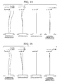
- FIG. 2 illustrates an aberration diagram of the zoom lens of exemplary embodiment 1 at the wide-angle end.
- FIG. 3 illustrates an aberration diagram of the zoom lens of exemplary embodiment 1 at the middle focal length.
- FIG. 4 illustrates an aberration diagram of the zoom lens of exemplary embodiment 1 at the telephoto end.
- FIGS. 5A, 5B, and 5C illustrate lens sectional views of a zoom lens of exemplary embodiment 2.
- FIG. 6 illustrates an aberration diagram of the zoom lens of exemplary embodiment 2 at the wide-angle end.
- FIG. 7 illustrates an aberration diagram of the zoom lens of exemplary embodiment 2 at the middle focal length.
- FIG. 8 illustrates an aberration diagram of the zoom lens of exemplary embodiment 2 at the telephoto end.
- FIGS. 9A, 9B, and 9C illustrate lens sectional views of a zoom lens of exemplary embodiment 3.
- FIG. 10 illustrates an aberration diagram of the zoom lens of exemplary embodiment 3 at the wide-angle end.
- FIG. 11 illustrates an aberration diagram of the zoom lens of exemplary embodiment 3 at the middle focal length.
- FIG. 12 illustrates an aberration diagram of the zoom lens of exemplary embodiment 3 at the telephoto end.
- FIGS. 13A, 13B, and 13C illustrate lens sectional views of a zoom lens of exemplary embodiment 4.
- FIG. 14 illustrates an aberration diagram of the zoom lens of exemplary embodiment 4 at the wide-angle end.
- FIG. 15 illustrates an aberration diagram of the zoom lens of exemplary embodiment 4 at the middle focal length.
- FIG. 16 illustrates an aberration diagram of the zoom lens of exemplary embodiment 4 at the telephoto end.
- FIGS. 17A, 17B, and 17C illustrate lens sectional views of a zoom lens of exemplary embodiment 5.
- FIG. 18 illustrates an aberration diagram of the zoom lens of exemplary embodiment 5 at the wide-angle end.
- FIG. 19 illustrates an aberration diagram of the zoom lens of exemplary embodiment 5 at the middle focal length.
- FIG. 20 illustrates an aberration diagram of the zoom lens of exemplary embodiment 5 at the telephoto end.
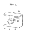
- FIG. 21 illustrates a schematic view of a digital still camera.
- exemplary embodiments are not limited to visual optical systems, for example the system can be designed for use with infrared and other wavelength systems.
- an infrared image pickup apparatus e.g., a detector measuring infrared markings.
- Exemplary embodiments can be used on various image pickup apparatus (e.g., solid-state image sensor, for example, a camcorder, a surveillance camera, equivalents, and other image pickup apparatus as known by one of ordinary skill in the relevant art) and are not limited to digital still cameras.
- image pickup apparatus e.g., solid-state image sensor, for example, a camcorder, a surveillance camera, equivalents, and other image pickup apparatus as known by one of ordinary skill in the relevant art
- image pickup apparatus e.g., solid-state image sensor, for example, a camcorder, a surveillance camera, equivalents, and other image pickup apparatus as known by one of ordinary skill in the relevant art
- Zoom lens systems and image pickup apparatus incorporating zoom lens systems will now be described.
- FIGS. 1A, 1B, and 1C illustrate lens sectional views of a zoom lens of exemplary embodiment 1 at the wide-angle end (short focal length end), the middle zoom position, and the telephoto end (long focal length end) respectively.
- FIGS. 2, 3, and 4 illustrate aberration diagrams of the zoom lens of exemplary embodiment 1 at the wide-angle end, the middle zoom position, and the telephoto end respectively.
- the zoom lens of exemplary embodiment 1 has a zoom ratio of about 1.91, and an F number of approximately 3.28 to 4.69. Note that other exemplary embodiments can have various zoom ratios and F numbers and any discussion herein is not intended to limit exemplary embodiments to the quantities stated.
- FIGS. 5A, 5B, and 5C illustrate lens sectional views of a zoom lens of exemplary embodiment 2 at the wide-angle end, the middle zoom position, and the telephoto end respectively.
- FIGS. 6, 7, and 8 illustrate aberration diagrams of the zoom lens of exemplary embodiment 2 at the wide-angle end, the middle zoom position, and the telephoto end respectively.
- the zoom lens of exemplary embodiment 2 has a zoom ratio of 1.91, and an F number of approximately 3.28 to 4.67.
- FIGS. 9A, 9B, and 9C illustrate lens sectional views of a zoom lens of exemplary embodiment 3 at the wide-angle end, the middle zoom position, and the telephoto end respectively.
- FIGS. 10, 11, and 12 illustrate aberration diagrams of the zoom lens of exemplary embodiment 3 at the wide-angle end, the middle zoom position, and the telephoto end respectively.
- the zoom lens of exemplary embodiment 3 has a zoom ratio of 1.96, and an F number of approximately 3.28 to 4.54.
- FIGS. 13A, 13B, and 13C illustrate lens sectional views of a zoom lens of exemplary embodiment 4 at the wide-angle end, the middle zoom position, and the telephoto end respectively.
- FIGS. 14, 15, and 16 illustrate aberration diagrams of the zoom lens of exemplary embodiment 4 at the wide-angle end, the middle zoom position, and the telephoto end respectively.
- the zoom lens of exemplary embodiment 4 has a zoom ratio of 1.91, and an F number of approximately 3.28 to 4.83.
- FIGS. 17A, 17B, and 17C illustrate lens sectional views of a zoom lens of exemplary embodiment 5 at the wide-angle end, the middle zoom position, and the telephoto end respectively.
- FIGS. 18, 19, and 20 illustrate aberration diagrams of the zoom lens of exemplary embodiment 5 at the wide-angle end, the middle zoom position, and the telephoto end respectively.
- the zoom lens of exemplary embodiment 5 has a zoom ratio of 1.91, and an F number of approximately 2.88 to 4.07.
- FIG. 21 illustrates a schematic view of a digital still camera (image pickup apparatus) having a zoom lens system according to at least one exemplary embodiment.
- the zoom lens of at least one exemplary embodiment can be a photographic lens system configured to be used in an image pickup apparatus.
- the left side is the object side
- the right side is the image side.
- reference character L1 denotes a first lens unit having negative refractive power (optical power, which is the inverse of the focal length)
- reference character L2 denotes a second lens unit having positive refractive power
- reference character L3 denotes a third lens unit having positive refractive power.
- Reference character SP denotes an aperture stop, which is located on the object side of the second lens unit L2 in exemplary embodiments 1 (FIGS. 1A-1C), 2 (FIGS. 5A-5C), 3 (FIGS. 9A-9C), and 5 (FIGS. 17A-17C), and on the image side of the second lens unit L2 in exemplary embodiment 4 (FIGS. 13A-13C).
- Reference character G denotes an optical block that is provided for design reasons and can correspond to an optical filter, a faceplate, a crystal low pass filter, or an infrared cut-off filter.
- Reference character IP denotes an image plane where a light-sensitive surface is placed.
- the zoom lens is used, as a photographic optical system for a camcorder or a digital still camera, the light-sensitive surface corresponds to the imaging surface of a solid-state image sensor (photoelectric transducer) (e.g., a CCD sensor or a CMOS sensor).
- a solid-state image sensor photoelectric transducer
- reference characters d and g denote the d line and the g line respectively
- reference characters ⁇ M and ⁇ S denote the meridional image surface and the sagittal image surface respectively.
- the lateral chromatic aberration (chromatic aberration of magnification) is shown by the g line.
- the wide-angle end and the telephoto end mean the zoom positions where the lens unit for variable magnification (e.g., second lens unit) is at either end of its mechanically movable range on the optical axis.
- the lens unit for variable magnification e.g., second lens unit
- the zoom lenses of exemplary embodiments 1 to 4 illustrated in FIGS. 1A to 1C, 5A to 5C, 9A to 9C, and 13A to 13C when zooming from the wide-angle end to the telephoto end, the first lens unit L1 can move in a curve convex toward the image side, and the second lens unit L2 can move toward the object side.
- the first lens unit L1 when zooming from the wide-angle end to the telephoto end, the first lens unit L1 can move in a curve convex toward the image side, the second lens unit L2 can move toward the object side such that the distance from the second lens unit L2 to the first lens unit L1 decreases, and the third lens unit L3 can move toward the object side such that the distance from the third lens unit L3 to the second lens unit L2 increases.
- the aperture stop SP can moves together with the second lens unit L2 when zooming.
- magnification variation can be performed by moving the second lens unit L2, with the movement of the image plane accompanying the magnification variation compensated by moving the first lens unit L1.
- the first lens unit L1 can be moved on the optical axis to focus.
- the third lens unit L3 can be moved on the optical axis to focus.
- Focusing by the first lens unit L1 may be performed by using a locus as an extension of a cam locus for zooming formed in a staircase pattern.
- the lens configuration of the second lens unit which can travel a relatively long distance when zooming
- the lens configuration of the first lens unit which can be configured to compensate the fluctuation of image plane due to magnification variation, so as to reduce the aberration fluctuation in zooming.
- the first lens unit L1 can include a first lens element G11 having negative refractive power and a second lens element G12 having positive refractive power.
- the first lens element G11 can have a meniscus shape, and its image side can be a concave aspherical surface. Namely, in the first lens element G11, the absolute value of the refractive power of the image-side surface can be greater than that of the object-side surface.
- the second lens element G12 can have a meniscus shape, and its object side can be a convex surface.
- the second lens element G12 can be formed of a material having an increased refractive index and an increased dispersion.
- the second lens unit L2 can include a third lens element G21, which can have positive refractive power and a fourth lens element G22, which can have negative refractive power.
- the third lens element G21 can have a biconvex shape, and its object side can be an aspherical surface.
- the absolute value of the refractive power of the object-side surface can be greater than that of the image-side surface.
- the fourth lens element G22 can have a meniscus shape, and its image side can be a concave aspherical surface.
- the absolute value of the refractive power of the image-side surface can be greater than that of the object-side surface.
- the third lens element G21 can be formed of a material having a reduced refractive index and a reduced dispersion
- the fourth lens element G22 can be formed of a material having an increased refractive index and an increased dispersion.
- the third lens unit L3 can include a single lens element (fifth lens element) having positive refractive power.
- At least one exemplary embodiment satisfies at least one of the following conditions. A different effect is obtained for each condition. - 0.6 ⁇ f 11 ⁇ f 12 ( f 1 ) 2 ⁇ - 0.2 7 ⁇ v 11 - v 12 ⁇ 15 1.8 ⁇ N 12 26 ⁇ v 12 45 ⁇ v 21 - v 22 ⁇ 50 1.5 ⁇ R 22 a + R 22 b R 22 a - R 22 b ⁇ 2.5 - 0.39 ⁇ Da / f 1 ⁇ - 0.3 - 2.4 ⁇ f 1 / fw ⁇ - 1.5
- f11 is the focal length of the first lens element G11
- f12 is the focal length of the second lens element G12
- f1 is the focal length of the first lens unit L1
- fw is the focal length of the entire system at the wide-angle end
- ⁇ 11 is the Abbe number of the material constituting the first lens element G11
- ⁇ 12 is the Abbe
- Abbe number vd ( Nd - 1 ) / ( NF - NC )
- Nd is the refractive index of the material for the d line
- NF is the refractive index of the material for the F line (refractive index for the wavelength hydrogen F (486.13 nm)
- NC is the refractive index of the material for the C line (refractive index of the material for the wavelength hydrogen C (656.27 nm)).
- Condition 1 relates to the focal lengths of the first lens element G11 and the second lens element G12 constituting the first lens unit L1.
- Condition 2 relates to the Abbe numbers of the materials constituting the first lens element G11 and the second lens element G12 constituting the first lens unit L1.
- at least one exemplary embodiment can satisfy both of conditions 1 and 2.
- the entire lens system may need to be large.
- ⁇ 11- ⁇ 12 In a power arrangement in the range of condition 1, if ⁇ 11- ⁇ 12 is above the upper limit of condition 2 or below the lower limit of condition 2, it can be difficult to improve the lateral chromatic aberration in the entire lens system. If ⁇ 11- ⁇ 12 is above the upper limit of condition 2, one may weaken the refractive powers of the two lenses constituting the first lens unit L1 in order to maintain a balance of the lateral chromatic aberration. As a result, condition 1 is not satisfied, and the coma flare can increase throughout the entire zoom range. If ⁇ 11- ⁇ 12 is below the lower limit of condition 2, one may strengthen the refractive powers of the two lenses constituting the first lens unit L1, although it may be difficult to ensure the edge of the second lens element G12 in the first lens unit L1.
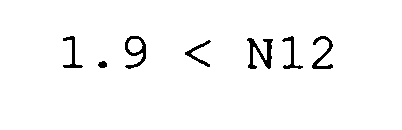
- Condition 3 relates to the refractive index of the material constituting the second lens element G12 in the first lens unit L1. If the refractive index N12 is below the lower limit of condition 3, the diameters of the lenses in the first lens unit L1 may be large, and it can be difficult to reduce the coma flare in the wide-angle range.
- Condition 4 relates to the Abbe number of the material constituting the second lens element G12 in the first lens unit L1. If the Abbe number v12 is below the lower limit of condition 4, it can be difficult to improve the lateral chromatic aberration in the lens system.
- Condition 5 relates to the Abbe numbers of the materials constituting the third lens element and the fourth lens element in the second lens unit L2. If the difference between the Abbe numbers (v21-v22) is not appropriate, that is to say, it is above the upper limit of condition 5 or below the lower limit of condition 5, it can be difficult to improve the axial chromatic aberration (longitudinal chromatic aberration) in the telephoto range.
- Condition 6 relates to the shape factor of the fourth lens element G22 in the second lens unit L2. If condition 6 is not satisfied, it can be difficult to reduce the coma flare in the periphery of the picture in the telephoto range.
- Condition 7 relates to the sum of the thicknesses of lenses in the first lens unit L1 and the distance between the lenses. If Da/f1 is above the upper limit of condition 7, a large thickness of the first lens unit L1 can cause the most object-side lens to be large, and consequently can cause the lens system to be large.
- a lens holder disposed between the first lens element G11 and the second lens element G12 may need to be thin, possibly decreasing the strength of the lens holder.
- Condition 8 relates to the focal length f1 of the first lens unit L1. If f1/fw is above the upper limit of condition 8, it can be difficult to improve the image plane curvature throughout the entire zoom range. If f1/fw is below the lower limit of condition 8, the total length of the zoom lens at the wide-angle end tends to be large.
- the numerical range of each condition can be as follows: - 0.5 ⁇ f 11 ⁇ f 12 ( f 1 ) 2 ⁇ - 0.25 10 ⁇ ⁇ 11 - ⁇ 12 ⁇ 14 1.95 ⁇ N 12 27 ⁇ ⁇ 12 46 ⁇ ⁇ 21 - ⁇ 22 ⁇ 48 1.7 ⁇ R 22 a + R 22 b R 22 a - R 22 b ⁇ 2.3 - 0.38 ⁇ Da / f 1 ⁇ - 0.35 - 2.2 ⁇ f 1 / fw ⁇ - 1.7
- a filter or a lens unit having small refractive power may be added on the object side of the first lens unit L1, between the lens units, or on the image side of the third lens unit L3, a filter or a lens unit having small refractive power may be added.
- the second lens element G12 in the first lens unit (L1) can satisfy both of the following conditions (3b) and (4): 1.9 ⁇ N 12 26 ⁇ ⁇ 12
- the lens configuration of each lens unit, the position of the aspherical surface in each lens unit, how each lens unit moves when zooming, and how focusing is performed can be optimized in each embodiment.
- the zoom lens has a zoom ratio of about 2x, is bright, has improved optical performance, and can be operatively connected to a digital still camera.
- reference numeral 20 denotes a camera main body
- reference numeral 21 denotes a photographic optical system which includes a zoom lens system in accordance exemplary embodiments
- reference numeral 22 denotes a solid-state image sensor (photoelectric transducer) (e.g., a CCD sensor or a CMOS sensor) sensing an object image via the photographic optical system
- reference numeral 23 denotes a memory for recording the object image sensed by the image sensor 22
- reference numeral 24 denotes a finder for observing the object image displayed on a display device (not shown, e.g., liquid crystal panel).
- the display device displays the object image formed on the image sensor 22.
- a zoom lens system can be used for an image pickup apparatus (e.g., a digital still camera), thereby achieving an image pickup apparatus that is compact, and has an improved optical performance.
- an image pickup apparatus e.g., a digital still camera
- i shows the order of surfaces from the object side
- Ri shows the radius of curvature of the ith surface
- Di shows the distance between the ith surface and the (i+1)th surface (the lens thickness or the air space)
- Ni and ⁇ i show the refractive index and the Abbe number for the d line respectively.
- the two most image-side surfaces are the two planes constituting the optical block G.
- k is the conic constant
- A, B, C, D, and E are the aspherical coefficients
- R is the paraxial radius of curvature.
- e-0x means " ⁇ 10 -x ".
- Reference character f denotes the focal length
- reference character Fno denotes the F-number
- reference character ⁇ denotes the half angle of view.
- Table 1 shows the relation between the conditions 1 to 8 and exemplary embodiments 1 to 5.
- Table 1 Condition Embodilment 1 2 3 4 5 (1) f 11 + f 12 f 1 ′ -0.39 -0.41 -0.40 -0.42 -0.31 (2) ⁇ 11 41.0 41.0 40.8 41.0 40.1 ⁇ 12 28.3 28.3 28.3 28.3 28.3 ⁇ 11- ⁇ 12 12.7 12.7 12.5 12.7 11.8 (3) N12 2.0033 2.0033 2.0033 2.0033 2.0033 (4) ⁇ 12 28.3 28.3 28.3 28.3 28.3 (5) ⁇ 21 70.2 70.2 70.2 70.2 ⁇ 22 24.1 24.1 24.1 24.1 24.1 24.1 24.1 23.9 24.1 23.9 ⁇ 21- ⁇ 22 46.17 46.17 46.33 46.17 46.33 (6) R22a 16.847 15.940 9.570 16.212 14.240 R22b 5.126 4.998 3.953 5.301 4.634 R 22 a + R 22 b R 22
Landscapes
- Physics & Mathematics (AREA)
- General Physics & Mathematics (AREA)
- Optics & Photonics (AREA)
- Lenses (AREA)
- Studio Devices (AREA)
Abstract
A zoom lens system comprising from the object side to the image side: a negative optical power first lens unit comprising a negative optical power first lens element and a positive optical power second lens element; and a positive optical power second lens unit. The distance between the first and second lens units changes during zooming. In a first embodiment, the focal lengths f1, f11, f12 of respective first lens unit and the first and second lens elements satisfy the condition -0.6 < ((f11 x f12)/f12) < - 0.2, and Abbe numbers v11 and v12 of respective materials of the first and second lens elements, satisfy the condition 7 < (v11 - v12) < 15. In a second embodiment, the refractive index N12 and the Abbe number v12 satisfy the conditions 1.8 < N12 and 26 < v12.
Description
- The present invention relates to a zoom lens system. More particularly, but not exclusively, the present invention relates to a zoom lens system suitable as an optical system for an image pickup apparatus.
- Recently, the technology of solid-state image sensors, such as a CCD, used in image pickup apparatuses, such as digital still cameras and camcorders, has made remarkable progress. In addition, the image pickup apparatuses have been reduced in size. Therefore, a compact, thin, and lightweight photographic lens system having improved optical performance is needed.
- A two-unit zoom lens has relatively improved optical performance, and its entire lens system is small. The two-unit zoom lens includes, from the object side to the image side, a first lens unit having negative refractive power and a second lens unit having positive refractive power, and changes the distance (air space) between the two lens units to perform zooming.
- The lens system of this two-unit zoom lens is composed of a relatively small number of lenses. Therefore, this two-unit zoom lens is commonly used in small lens systems.
- A small two-unit zoom lens whose first lens unit consists of a negative lens and a positive lens and whose second lens unit consists of a positive lens and a negative lens is discussed in Japanese Patent Laid-Open No. 6-273670, Japanese Patent Laid-Open No. 9-033810, and Japanese Patent Laid-Open No. 11-052235 (corresponding to U.S. Patent No. 6,081,389).
- A two-unit zoom lens whose second lens unit consists of a first lens subunit having positive refractive power and a second lens subunit having positive refractive power, the second lens subunit performing focusing, is discussed in Japanese Patent Laid-Open No. 2000-9997 (corresponding to U.S. Patent No. 6,124,987).
- A three-unit zoom lens suitable for a small image pickup apparatus having a high-resolution image sensor, the zoom lens including three lens units having negative, positive, and positive refractive power respectively, is discussed in Japanese Patent Laid-Open No. 2000-147381 (corresponding to U.S. Patent No. 6,243,213) and Japanese Patent Laid-Open No. 2000-284177 (corresponding to U.S. Patent No. 6,351,337).
- A small three-unit zoom lens whose second lens unit consists of a positive lens and a negative lens is discussed in Japanese Patent Laid-Open No. 2000-9999 (corresponding to U.S. Patent No. 6,172,818).
- The two-unit zoom lenses and the three-unit zoom lenses discussed in the above documents can be improved in optical performance in order to be used for an image pickup apparatus using a high-resolution solid-state image sensor.
- At least one exemplary embodiment is directed to a zoom lens system that is configured to be operatively connected to an image pickup apparatus (e.g., one using a solid-state image sensor), compact, and has excellent optical performance.
- An exemplary embodiment includes, from the object side to the image side, a first lens unit having negative optical power and a second lens unit having positive optical power. The distance between the two lens units can change during zooming. The first lens unit can include a first lens element having negative optical power and a second lens element having positive optical power. In such a zoom lens system, the optical power of the two lens elements constituting the first lens unit and the material constituting the lens elements are set appropriately as described below.
- Further features of the present invention will become apparent from the following description of exemplary embodiments (with reference to the attached drawings).
- FIGS. 1A, 1B, and 1C illustrate lens sectional views of a zoom lens of exemplary embodiment 1.
- FIG. 2 illustrates an aberration diagram of the zoom lens of exemplary embodiment 1 at the wide-angle end.
- FIG. 3 illustrates an aberration diagram of the zoom lens of exemplary embodiment 1 at the middle focal length.
- FIG. 4 illustrates an aberration diagram of the zoom lens of exemplary embodiment 1 at the telephoto end.
- FIGS. 5A, 5B, and 5C illustrate lens sectional views of a zoom lens of exemplary embodiment 2.
- FIG. 6 illustrates an aberration diagram of the zoom lens of exemplary embodiment 2 at the wide-angle end.
- FIG. 7 illustrates an aberration diagram of the zoom lens of exemplary embodiment 2 at the middle focal length.
- FIG. 8 illustrates an aberration diagram of the zoom lens of exemplary embodiment 2 at the telephoto end.
- FIGS. 9A, 9B, and 9C illustrate lens sectional views of a zoom lens of exemplary embodiment 3.
- FIG. 10 illustrates an aberration diagram of the zoom lens of exemplary embodiment 3 at the wide-angle end.
- FIG. 11 illustrates an aberration diagram of the zoom lens of exemplary embodiment 3 at the middle focal length.
- FIG. 12 illustrates an aberration diagram of the zoom lens of exemplary embodiment 3 at the telephoto end.
- FIGS. 13A, 13B, and 13C illustrate lens sectional views of a zoom lens of exemplary embodiment 4.
- FIG. 14 illustrates an aberration diagram of the zoom lens of exemplary embodiment 4 at the wide-angle end.
- FIG. 15 illustrates an aberration diagram of the zoom lens of exemplary embodiment 4 at the middle focal length.
- FIG. 16 illustrates an aberration diagram of the zoom lens of exemplary embodiment 4 at the telephoto end.
- FIGS. 17A, 17B, and 17C illustrate lens sectional views of a zoom lens of exemplary embodiment 5.
- FIG. 18 illustrates an aberration diagram of the zoom lens of exemplary embodiment 5 at the wide-angle end.
- FIG. 19 illustrates an aberration diagram of the zoom lens of exemplary embodiment 5 at the middle focal length.
- FIG. 20 illustrates an aberration diagram of the zoom lens of exemplary embodiment 5 at the telephoto end.
- FIG. 21 illustrates a schematic view of a digital still camera.
- The following description of exemplary embodiment(s) is merely illustrative in nature and is in no way intended to limit the invention, its application, its equivalents, or uses.
- Processes, techniques, apparatus, and materials as known by one of ordinary skill in the art may not be discussed in detail but are intended to be part of the enabling description where appropriate. For example lens and lens units are discussed and any material or method that can be used to form lenses should fall within the scope of exemplary embodiments (e.g., glass, Si, or etching, molding). Additionally the actual size of the lens may not be discussed however any size from macro lenses to micro and nano lenses are intended to lie within the scope of exemplary embodiments (e.g., lenses with diameters of nanometer size, micro size, centimeter, and meter sizes).
- Additionally exemplary embodiments are not limited to visual optical systems, for example the system can be designed for use with infrared and other wavelength systems. For example an infrared image pickup apparatus (e.g., a detector measuring infrared markings).
- Exemplary embodiments can be used on various image pickup apparatus (e.g., solid-state image sensor, for example, a camcorder, a surveillance camera, equivalents, and other image pickup apparatus as known by one of ordinary skill in the relevant art) and are not limited to digital still cameras.
- Zoom lens systems and image pickup apparatus incorporating zoom lens systems, according to at least a few exemplary embodiments, will now be described.
- FIGS. 1A, 1B, and 1C illustrate lens sectional views of a zoom lens of exemplary embodiment 1 at the wide-angle end (short focal length end), the middle zoom position, and the telephoto end (long focal length end) respectively. FIGS. 2, 3, and 4 illustrate aberration diagrams of the zoom lens of exemplary embodiment 1 at the wide-angle end, the middle zoom position, and the telephoto end respectively. The zoom lens of exemplary embodiment 1 has a zoom ratio of about 1.91, and an F number of approximately 3.28 to 4.69. Note that other exemplary embodiments can have various zoom ratios and F numbers and any discussion herein is not intended to limit exemplary embodiments to the quantities stated.
- FIGS. 5A, 5B, and 5C illustrate lens sectional views of a zoom lens of exemplary embodiment 2 at the wide-angle end, the middle zoom position, and the telephoto end respectively. FIGS. 6, 7, and 8 illustrate aberration diagrams of the zoom lens of exemplary embodiment 2 at the wide-angle end, the middle zoom position, and the telephoto end respectively. The zoom lens of exemplary embodiment 2 has a zoom ratio of 1.91, and an F number of approximately 3.28 to 4.67.
- FIGS. 9A, 9B, and 9C illustrate lens sectional views of a zoom lens of exemplary embodiment 3 at the wide-angle end, the middle zoom position, and the telephoto end respectively. FIGS. 10, 11, and 12 illustrate aberration diagrams of the zoom lens of exemplary embodiment 3 at the wide-angle end, the middle zoom position, and the telephoto end respectively. The zoom lens of exemplary embodiment 3 has a zoom ratio of 1.96, and an F number of approximately 3.28 to 4.54.
- FIGS. 13A, 13B, and 13C illustrate lens sectional views of a zoom lens of exemplary embodiment 4 at the wide-angle end, the middle zoom position, and the telephoto end respectively. FIGS. 14, 15, and 16 illustrate aberration diagrams of the zoom lens of exemplary embodiment 4 at the wide-angle end, the middle zoom position, and the telephoto end respectively. The zoom lens of exemplary embodiment 4 has a zoom ratio of 1.91, and an F number of approximately 3.28 to 4.83.
- FIGS. 17A, 17B, and 17C illustrate lens sectional views of a zoom lens of exemplary embodiment 5 at the wide-angle end, the middle zoom position, and the telephoto end respectively. FIGS. 18, 19, and 20 illustrate aberration diagrams of the zoom lens of exemplary embodiment 5 at the wide-angle end, the middle zoom position, and the telephoto end respectively. The zoom lens of exemplary embodiment 5 has a zoom ratio of 1.91, and an F number of approximately 2.88 to 4.07.
- FIG. 21 illustrates a schematic view of a digital still camera (image pickup apparatus) having a zoom lens system according to at least one exemplary embodiment.
- The zoom lens of at least one exemplary embodiment can be a photographic lens system configured to be used in an image pickup apparatus. In each lens sectional view, the left side is the object side, and the right side is the image side.
- In the lens sectional views of FIGS. 1A to 1C, 5A to 5C, 9A to 9C, 13A to 13C, and 17A to 17C, reference character L1 denotes a first lens unit having negative refractive power (optical power, which is the inverse of the focal length), reference character L2 denotes a second lens unit having positive refractive power, and reference character L3 denotes a third lens unit having positive refractive power. Reference character SP denotes an aperture stop, which is located on the object side of the second lens unit L2 in exemplary embodiments 1 (FIGS. 1A-1C), 2 (FIGS. 5A-5C), 3 (FIGS. 9A-9C), and 5 (FIGS. 17A-17C), and on the image side of the second lens unit L2 in exemplary embodiment 4 (FIGS. 13A-13C).
- Reference character G denotes an optical block that is provided for design reasons and can correspond to an optical filter, a faceplate, a crystal low pass filter, or an infrared cut-off filter. Reference character IP denotes an image plane where a light-sensitive surface is placed. When the zoom lens is used, as a photographic optical system for a camcorder or a digital still camera, the light-sensitive surface corresponds to the imaging surface of a solid-state image sensor (photoelectric transducer) (e.g., a CCD sensor or a CMOS sensor).
- In each aberration diagram, reference characters d and g denote the d line and the g line respectively, and reference characters ΔM and ΔS denote the meridional image surface and the sagittal image surface respectively. The lateral chromatic aberration (chromatic aberration of magnification) is shown by the g line.
- In each embodiment, the wide-angle end and the telephoto end mean the zoom positions where the lens unit for variable magnification (e.g., second lens unit) is at either end of its mechanically movable range on the optical axis.
- In the zoom lenses of exemplary embodiments 1 to 4 illustrated in FIGS. 1A to 1C, 5A to 5C, 9A to 9C, and 13A to 13C, when zooming from the wide-angle end to the telephoto end, the first lens unit L1 can move in a curve convex toward the image side, and the second lens unit L2 can move toward the object side.
- In the zoom lens of exemplary embodiment 5 illustrated in FIGS. 17A to 17C, when zooming from the wide-angle end to the telephoto end, the first lens unit L1 can move in a curve convex toward the image side, the second lens unit L2 can move toward the object side such that the distance from the second lens unit L2 to the first lens unit L1 decreases, and the third lens unit L3 can move toward the object side such that the distance from the third lens unit L3 to the second lens unit L2 increases.
- In at least one exemplary embodiment, the aperture stop SP can moves together with the second lens unit L2 when zooming.
- In the zoom lens of at least one exemplary embodiment, magnification variation can be performed by moving the second lens unit L2, with the movement of the image plane accompanying the magnification variation compensated by moving the first lens unit L1.
- In exemplary embodiments 1 to 4, the first lens unit L1 can be moved on the optical axis to focus. In exemplary embodiment 5, the third lens unit L3 can be moved on the optical axis to focus.
- Focusing by the first lens unit L1 may be performed by using a locus as an extension of a cam locus for zooming formed in a staircase pattern.
- In general, in order for a two-unit zoom lens and a three-unit zoom lens to have good optical performance throughout the entire zoom range, to reduce the number of lenses, and to reduce the thickness of the lens system, it is effective to use an aspherical surface in an appropriate part in the lens system.
- In addition, it is appropriate to set the lens configuration of the second lens unit, which can travel a relatively long distance when zooming, and also set the lens configuration of the first lens unit, which can be configured to compensate the fluctuation of image plane due to magnification variation, so as to reduce the aberration fluctuation in zooming.
- In at least one exemplary embodiment, the first lens unit L1 can include a first lens element G11 having negative refractive power and a second lens element G12 having positive refractive power. The first lens element G11 can have a meniscus shape, and its image side can be a concave aspherical surface. Namely, in the first lens element G11, the absolute value of the refractive power of the image-side surface can be greater than that of the object-side surface. The second lens element G12 can have a meniscus shape, and its object side can be a convex surface.
- The second lens element G12 can be formed of a material having an increased refractive index and an increased dispersion.
- The second lens unit L2 can include a third lens element G21, which can have positive refractive power and a fourth lens element G22, which can have negative refractive power. The third lens element G21 can have a biconvex shape, and its object side can be an aspherical surface. The absolute value of the refractive power of the object-side surface can be greater than that of the image-side surface. The fourth lens element G22 can have a meniscus shape, and its image side can be a concave aspherical surface. The absolute value of the refractive power of the image-side surface can be greater than that of the object-side surface.
- The third lens element G21 can be formed of a material having a reduced refractive index and a reduced dispersion, and the fourth lens element G22 can be formed of a material having an increased refractive index and an increased dispersion.
- Thus, the axial chromatic aberration can be well compensated.
- In exemplary embodiment 5, the third lens unit L3 can include a single lens element (fifth lens element) having positive refractive power.
- At least one exemplary embodiment satisfies at least one of the following conditions. A different effect is obtained for each condition.





- In the above conditions, the Abbe numbers and the refractive indices are for the d line, where the d-line indicates the bright line spectrum of He atom. Abbe number vd is represented by the following formula:

- Nd is the refractive index of the material for the d line, NF is the refractive index of the material for the F line (refractive index for the wavelength hydrogen F (486.13 nm)), and NC is the refractive index of the material for the C line (refractive index of the material for the wavelength hydrogen C (656.27 nm)). Next, the technical meaning of each condition will be described.
- Condition 1 relates to the focal lengths of the first lens element G11 and the second lens element G12 constituting the first lens unit L1. Condition 2 relates to the Abbe numbers of the materials constituting the first lens element G11 and the second lens element G12 constituting the first lens unit L1. In order to reduce the coma flare and improve chromatic aberration throughout the zoom range, at least one exemplary embodiment can satisfy both of conditions 1 and 2.
- In order to appropriately strengthen the refractive powers of the two lenses constituting the first lens unit L1, and to maintain a balance of the chromatic aberration with the lenses having somewhat strong refractive powers, one may maintain the difference between the Abbe numbers of the materials of the two lenses constituting the first lens unit L1. Conditions for it are mathematically represented by conditions 1 and 2.
- If the refractive powers of the lenses are too strong and f11×f12/ (f1)2 is above the upper limit of condition 1, it can be difficult to improve the oblique aberration in the wide-angle range. If the refractive powers of the lenses are too weak and f11×f12/ (f1)2 is below the lower limit of condition 1, the entire lens system may need to be large.
- In a power arrangement in the range of condition 1, if ν11-ν12 is above the upper limit of condition 2 or below the lower limit of condition 2, it can be difficult to improve the lateral chromatic aberration in the entire lens system. If ν11-ν12 is above the upper limit of condition 2, one may weaken the refractive powers of the two lenses constituting the first lens unit L1 in order to maintain a balance of the lateral chromatic aberration. As a result, condition 1 is not satisfied, and the coma flare can increase throughout the entire zoom range. If ν11-ν12 is below the lower limit of condition 2, one may strengthen the refractive powers of the two lenses constituting the first lens unit L1, although it may be difficult to ensure the edge of the second lens element G12 in the first lens unit L1.
- Condition 3 relates to the refractive index of the material constituting the second lens element G12 in the first lens unit L1. If the refractive index N12 is below the lower limit of condition 3, the diameters of the lenses in the first lens unit L1 may be large, and it can be difficult to reduce the coma flare in the wide-angle range.
- Condition 4 relates to the Abbe number of the material constituting the second lens element G12 in the first lens unit L1. If the Abbe number v12 is below the lower limit of condition 4, it can be difficult to improve the lateral chromatic aberration in the lens system.
- Condition 5 relates to the Abbe numbers of the materials constituting the third lens element and the fourth lens element in the second lens unit L2. If the difference between the Abbe numbers (v21-v22) is not appropriate, that is to say, it is above the upper limit of condition 5 or below the lower limit of condition 5, it can be difficult to improve the axial chromatic aberration (longitudinal chromatic aberration) in the telephoto range.
- Condition 6 relates to the shape factor of the fourth lens element G22 in the second lens unit L2. If condition 6 is not satisfied, it can be difficult to reduce the coma flare in the periphery of the picture in the telephoto range.
- Condition 7 relates to the sum of the thicknesses of lenses in the first lens unit L1 and the distance between the lenses. If Da/f1 is above the upper limit of condition 7, a large thickness of the first lens unit L1 can cause the most object-side lens to be large, and consequently can cause the lens system to be large.
- If the thickness of the first lens unit L1 is small and Da/f1 is below the lower limit of condition 7, a lens holder disposed between the first lens element G11 and the second lens element G12 may need to be thin, possibly decreasing the strength of the lens holder.
- Condition 8 relates to the focal length f1 of the first lens unit L1. If f1/fw is above the upper limit of condition 8, it can be difficult to improve the image plane curvature throughout the entire zoom range. If f1/fw is below the lower limit of condition 8, the total length of the zoom lens at the wide-angle end tends to be large.
- In at least one exemplary embodiment, the numerical range of each condition can be as follows:



- In the above exemplary embodiments, on the object side of the first lens unit L1, between the lens units, or on the image side of the third lens unit L3, a filter or a lens unit having small refractive power may be added.
- In the above exemplary embodiment, the second lens element G12 in the first lens unit (L1) can satisfy both of the following conditions (3b) and (4):


- As described above, the lens configuration of each lens unit, the position of the aspherical surface in each lens unit, how each lens unit moves when zooming, and how focusing is performed can be optimized in each embodiment. Thus, although the number of lenses can be reduced so as to shorten the total length of the zoom lens, in at least one exemplary embodiment, the zoom lens has a zoom ratio of about 2x, is bright, has improved optical performance, and can be operatively connected to a digital still camera.
- Next, an exemplary embodiment of a digital still camera (image pickup apparatus) configured to use a zoom lens system in accordance with exemplary embodiments as a photographic optical system, will be described with reference to FIG. 21. In FIG. 21,
reference numeral 20 denotes a camera main body,reference numeral 21 denotes a photographic optical system which includes a zoom lens system in accordance exemplary embodiments,reference numeral 22 denotes a solid-state image sensor (photoelectric transducer) (e.g., a CCD sensor or a CMOS sensor) sensing an object image via the photographicoptical system 21,reference numeral 23 denotes a memory for recording the object image sensed by theimage sensor 22, andreference numeral 24 denotes a finder for observing the object image displayed on a display device (not shown, e.g., liquid crystal panel). The display device displays the object image formed on theimage sensor 22. - As described above, a zoom lens system according to exemplary embodiments can be used for an image pickup apparatus (e.g., a digital still camera), thereby achieving an image pickup apparatus that is compact, and has an improved optical performance.
- Next, numerical embodiments corresponding to the exemplary embodiments will be shown. In each numerical embodiment, i shows the order of surfaces from the object side, Ri shows the radius of curvature of the ith surface, Di shows the distance between the ith surface and the (i+1)th surface (the lens thickness or the air space), and Ni and νi show the refractive index and the Abbe number for the d line respectively.
- The two most image-side surfaces are the two planes constituting the optical block G.
- When a displacement in the direction of the optical axis at a height from the optical axis (h) referenced to the surface vertex is x, the aspherical shape is represented by the following formula:

- Incidentally, "e-0x" means "×10-x". Reference character f denotes the focal length, reference character Fno denotes the F-number, and reference character ω denotes the half angle of view.
- Table 1 shows the relation between the conditions 1 to 8 and exemplary embodiments 1 to 5.


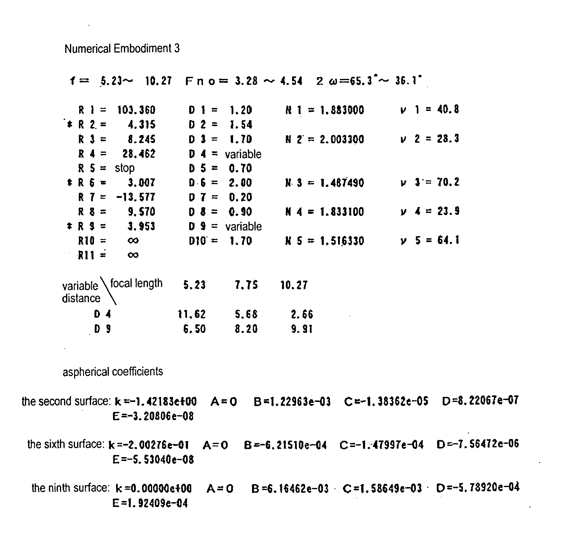

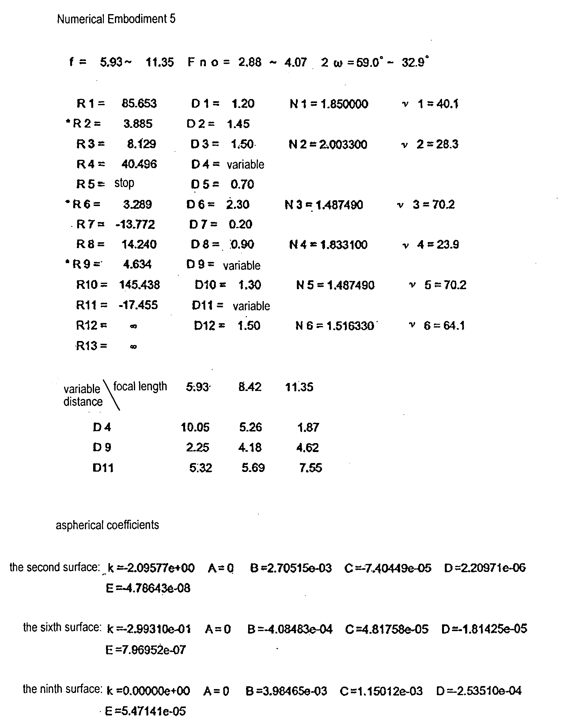
Table 1 Condition Embodilment 1 2 3 4 5 (1) 
-0.39 -0.41 -0.40 -0.42 -0.31 (2) ν11 41.0 41.0 40.8 41.0 40.1 ν12 28.3 28.3 28.3 28.3 28.3 ν11-ν12 12.7 12.7 12.5 12.7 11.8 (3) N12 2.0033 2.0033 2.0033 2.0033 2.0033 (4) ν12 28.3 28.3 28.3 28.3 28.3 (5) ν21 70.2 70.2 70.2 70.2 70.2 ν22 24.1 24.1 23.9 24.1 23.9 ν21-ν22 46.17 46.17 46.33 46.17 46.33 (6) R22a 16.847 15.940 9.570 16.212 14.240 R22b 5.126 4.998 3.953 5.301 4.634 
1.9 1.9 2.4 2.06 1.96 (7) Da 4.05 4.1 4.44 3.85 4.15 f1 -10.94 -11.1 -12 -10.1 -12.2 Da/f1 -0.37 -0.37 -0.37 -0.38 -0.34 (8) f1 10.94 -11.1 -12 -10.1 -12.2 fw 5.94 5.94 5.23 5.94 5.93 f1/fw -1.85 -1.85 -2.27 -1.70 -2.09 - While the present invention has been described with reference to exemplary embodiments, it is to be understood that the invention is not limited to the disclosed exemplary embodiments. The scope of the following claims is to be accorded the broadest interpretation so as to encompass all modifications, equivalent structures and functions.
Claims (13)
- A zoom lens system comprising from the object side to the image side:a first lens unit having negative optical power, the first lens unit consisting of a first lens element having negative optical power and a second lens element having positive optical power; anda second lens unit having positive optical power,wherein the distance between the first lens unit and the second lens unit changes during zooming, andwherein a focal length (f1) of the first lens unit, a focal length (f11) of the first lens element, a focal length (f12) of the second lens element satisfy the following first condition:


- The zoom lens system according to Claim 1, wherein a refractive index (N12) of a material constituting the second lens element satisfies the following condition:

- The zoom lens system according to Claim 1, wherein a refractive index (N12) and an Abbe number (ν12) of a material constituting the second lens element satisfy the following conditions:


- A zoom lens system comprising from the object side to the image side:a first lens unit having negative optical power, the first lens unit consisting of a first lens element having negative optical power and a second lens element having positive optical power; anda second lens unit having positive optical power,wherein the distance between the first lens unit and the second lens unit changes during zooming, andwherein a refractive index (N12) and an Abbe number (ν12) of a material constituting the second lens element satisfy the following conditions:

- The zoom lens system according to any one of Claims 1 to 4, wherein the second lens unit consists of a third lens element having positive optical power and a fourth lens element having negative optical power.
- The zoom lens system according to Claim 5, wherein an Abbe number (ν21) of a material constituting the third lens element and an Abbe number (v22) of a material constituting the fourth lens element satisfy the following condition:

- The zoom lens system according to Claim 5 or 6, wherein a radius of curvature (R22a) of the object-side surface of the fourth lens element and a radius of curvature (R22b) of the image-side surface of the fourth lens element satisfy the following condition:

- The zoom lens system according to any one of Claims 1 to 7, wherein the first lens element has a shape in which the absolute value of optical power of the image-side surface is greater than that of the object-side surface, and the second lens element has a meniscus shape in which the object side is convex.
- The zoom lens system according to any one of Claims 1 to 8, further comprising an aperture stop disposed on the object side or the image side of the second lens unit.
- The zoom lens system according to any one of Claims 1 to 9, wherein a length (Da) between a point on the object-side surface of the first lens unit (L1) nearest the object and a point on the image-side surface of the first lens unit (L1) nearest the image and a focal length (f1) of the first lens unit satisfy the following condition:

- The zoom lens system according to any one of Claims 1 to 10, wherein a focal length (f1) of the first lens unit and a focal length (fw) of the entire zoom lens system at the wide-angle end satisfy the following condition:

- The zoom lens system according to any one of Claims 1 to 11, wherein the zoom lens system is arranged to form an image on a solid-state image sensor.
- An imaging apparatus comprising:the zoom lens system according to any one of Claims 1 to 12; anda solid-state image sensor arranged to sense an image formed by the zoom lens system.
Applications Claiming Priority (1)
| Application Number | Priority Date | Filing Date | Title |
|---|---|---|---|
| JP2004203857A JP4617107B2 (en) | 2004-07-09 | 2004-07-09 | Zoom lens and imaging apparatus having the same |
Publications (2)
| Publication Number | Publication Date |
|---|---|
| EP1615060A1 true EP1615060A1 (en) | 2006-01-11 |
| EP1615060B1 EP1615060B1 (en) | 2009-09-23 |
Family
ID=34941810
Family Applications (1)
| Application Number | Title | Priority Date | Filing Date |
|---|---|---|---|
| EP05254208A Expired - Lifetime EP1615060B1 (en) | 2004-07-09 | 2005-07-05 | Zoom lens system and image pickup apparatus having the same |
Country Status (5)
| Country | Link |
|---|---|
| US (1) | US7139132B2 (en) |
| EP (1) | EP1615060B1 (en) |
| JP (1) | JP4617107B2 (en) |
| CN (1) | CN100474026C (en) |
| DE (1) | DE602005016750D1 (en) |
Cited By (1)
| Publication number | Priority date | Publication date | Assignee | Title |
|---|---|---|---|---|
| EP1892550A1 (en) * | 2006-08-21 | 2008-02-27 | Fujinon Corporation | Retrofocus type of zoom lens having three lens groups |
Families Citing this family (6)
| Publication number | Priority date | Publication date | Assignee | Title |
|---|---|---|---|---|
| US7403341B2 (en) * | 2005-06-16 | 2008-07-22 | Olympus Imaging Corp. | Zoom lens system and electronic image pickup apparatus using the same |
| US7411746B2 (en) * | 2006-02-24 | 2008-08-12 | Hoya Corporation | Wide-angle lens system |
| KR101994284B1 (en) * | 2013-01-11 | 2019-09-30 | 한화테크윈 주식회사 | Zoom lens system |
| CN105900006B (en) * | 2014-01-10 | 2018-05-25 | 夏普株式会社 | camera assembly |
| CN105527693B (en) * | 2014-10-24 | 2018-07-20 | 玉晶光电(厦门)有限公司 | The electronic device of optical imaging lens and the application camera lens |
| CN106896500B (en) * | 2015-12-18 | 2020-10-16 | 台达电子工业股份有限公司 | Display device |
Citations (3)
| Publication number | Priority date | Publication date | Assignee | Title |
|---|---|---|---|---|
| US5663836A (en) * | 1993-08-10 | 1997-09-02 | Olympus Optical Co., Ltd. | Compact zoom lens system comprising two lens units |
| US5875060A (en) * | 1995-02-24 | 1999-02-23 | Minolta Co., Ltd. | Zoom lens system |
| EP1326119A2 (en) * | 2002-01-07 | 2003-07-09 | Canon Kabushiki Kaisha | Image reading apparatus with focal point position adjusting function |
Family Cites Families (20)
| Publication number | Priority date | Publication date | Assignee | Title |
|---|---|---|---|---|
| US566836A (en) * | 1896-09-01 | Vehicle-seat | ||
| US5283693A (en) * | 1990-06-13 | 1994-02-01 | Minolta Camera Kabushiki Kaisha | Compact zoom lens system |
| JP3033141B2 (en) * | 1990-06-22 | 2000-04-17 | ミノルタ株式会社 | Compact zoom lens |
| JP3200925B2 (en) * | 1992-03-05 | 2001-08-20 | 株式会社ニコン | Zoom lens with wide angle of view |
| JPH06273670A (en) * | 1993-03-18 | 1994-09-30 | Minolta Camera Co Ltd | Zoom lens using plastic lens |
| JPH0933809A (en) * | 1995-07-18 | 1997-02-07 | Sony Corp | Zoom lens |
| JPH0933810A (en) * | 1995-07-20 | 1997-02-07 | Sony Corp | Zoom lens |
| JP3564914B2 (en) * | 1997-01-30 | 2004-09-15 | ミノルタ株式会社 | Zoom lens |
| US6081389A (en) * | 1997-07-31 | 2000-06-27 | Canon Kabushiki Kaisha | Zoom lens of retrofocus type |
| JPH1152235A (en) * | 1997-07-31 | 1999-02-26 | Canon Inc | Zoom lens |
| JP3843607B2 (en) * | 1998-06-19 | 2006-11-08 | コニカミノルタビジネステクノロジーズ株式会社 | Zoom lens |
| JP3773155B2 (en) | 1998-06-26 | 2006-05-10 | 富士写真フイルム株式会社 | Zoom lens |
| US6243213B1 (en) * | 1998-08-31 | 2001-06-05 | Konica Corporation | Zoom lens and camera having the zoom lens |
| JP2000147381A (en) | 1998-08-31 | 2000-05-26 | Konica Corp | Zoom lens and camera provided with the same |
| JP3606548B2 (en) * | 1999-03-31 | 2005-01-05 | フジノン株式会社 | 3 group zoom lens |
| JP4217415B2 (en) * | 2001-04-04 | 2009-02-04 | オリンパス株式会社 | Electronic imaging device |
| JP2002323654A (en) * | 2001-04-25 | 2002-11-08 | Kyocera Corp | Compact zoom lens |
| JP3503941B2 (en) * | 2002-02-04 | 2004-03-08 | 富士写真光機株式会社 | 3-group zoom lens |
| JP4244288B2 (en) * | 2002-08-29 | 2009-03-25 | フジノン株式会社 | 3 group zoom lens |
| JP4497514B2 (en) * | 2003-09-11 | 2010-07-07 | フジノン株式会社 | Wide angle zoom lens |
-
2004
- 2004-07-09 JP JP2004203857A patent/JP4617107B2/en not_active Expired - Fee Related
-
2005
- 2005-06-27 US US11/168,164 patent/US7139132B2/en not_active Expired - Fee Related
- 2005-07-05 DE DE602005016750T patent/DE602005016750D1/en not_active Expired - Lifetime
- 2005-07-05 EP EP05254208A patent/EP1615060B1/en not_active Expired - Lifetime
- 2005-07-08 CN CNB2005100832719A patent/CN100474026C/en not_active Expired - Fee Related
Patent Citations (3)
| Publication number | Priority date | Publication date | Assignee | Title |
|---|---|---|---|---|
| US5663836A (en) * | 1993-08-10 | 1997-09-02 | Olympus Optical Co., Ltd. | Compact zoom lens system comprising two lens units |
| US5875060A (en) * | 1995-02-24 | 1999-02-23 | Minolta Co., Ltd. | Zoom lens system |
| EP1326119A2 (en) * | 2002-01-07 | 2003-07-09 | Canon Kabushiki Kaisha | Image reading apparatus with focal point position adjusting function |
Cited By (1)
| Publication number | Priority date | Publication date | Assignee | Title |
|---|---|---|---|---|
| EP1892550A1 (en) * | 2006-08-21 | 2008-02-27 | Fujinon Corporation | Retrofocus type of zoom lens having three lens groups |
Also Published As
| Publication number | Publication date |
|---|---|
| JP4617107B2 (en) | 2011-01-19 |
| CN1719299A (en) | 2006-01-11 |
| US7139132B2 (en) | 2006-11-21 |
| DE602005016750D1 (en) | 2009-11-05 |
| EP1615060B1 (en) | 2009-09-23 |
| JP2006023678A (en) | 2006-01-26 |
| CN100474026C (en) | 2009-04-01 |
| US20060007560A1 (en) | 2006-01-12 |
Similar Documents
| Publication | Publication Date | Title |
|---|---|---|
| US7894135B2 (en) | Zoom lens and image pickup apparatus including the lens | |
| US7443600B2 (en) | Zoom lens and image pickup apparatus having the same | |
| CN100595622C (en) | Zoom lens system, imaging device and shooting equipment | |
| EP2407810B1 (en) | Zoom lens and image pickup apparatus | |
| EP1998204B1 (en) | Zoom lens of the telephoto type having four groups, rear focusing and an image shake correction function | |
| US8339501B2 (en) | Zoom lens system, imaging device and camera | |
| US7443605B2 (en) | Zoom lens, imaging device, and camera having imaging device | |
| US8107171B2 (en) | Zoom lens system and image pickup apparatus including the same | |
| US20070121215A1 (en) | Zoom lens system and image-pickup apparatus including same | |
| JP4323796B2 (en) | Zoom lens and imaging apparatus having the same | |
| US20080062532A1 (en) | Zoom lens and image pickup apparatus | |
| US7796345B2 (en) | Zoom lens system | |
| JP5939788B2 (en) | Zoom lens and imaging apparatus having the same | |
| JP4444625B2 (en) | Zoom lens and imaging apparatus having the same | |
| US7236308B2 (en) | Zoom lens system, imaging device, and camera | |
| US20100277812A1 (en) | Zoom lens | |
| JP3026130B2 (en) | Aspherical zoom lens and video camera using it | |
| US7319563B2 (en) | Zoom lens system, imaging device and camera | |
| JP3810061B2 (en) | Zoom lens | |
| EP1615060B1 (en) | Zoom lens system and image pickup apparatus having the same | |
| JP4617108B2 (en) | Zoom lens and imaging apparatus having the same | |
| US7161742B2 (en) | Small zoom lens, and digital camera and video camera both having same | |
| CN114326064B (en) | Zoom lens and camera device | |
| JP3056338B2 (en) | Aspherical zoom lens and video camera using it | |
| US20240329367A1 (en) | Zoom lens and imaging apparatus including the same |
Legal Events
| Date | Code | Title | Description |
|---|---|---|---|
| PUAI | Public reference made under article 153(3) epc to a published international application that has entered the european phase |
Free format text: ORIGINAL CODE: 0009012 |
|
| AK | Designated contracting states |
Kind code of ref document: A1 Designated state(s): AT BE BG CH CY CZ DE DK EE ES FI FR GB GR HU IE IS IT LI LT LU LV MC NL PL PT RO SE SI SK TR |
|
| AX | Request for extension of the european patent |
Extension state: AL BA HR MK YU |
|
| 17P | Request for examination filed |
Effective date: 20060621 |
|
| AKX | Designation fees paid |
Designated state(s): DE FR |
|
| GRAP | Despatch of communication of intention to grant a patent |
Free format text: ORIGINAL CODE: EPIDOSNIGR1 |
|
| GRAS | Grant fee paid |
Free format text: ORIGINAL CODE: EPIDOSNIGR3 |
|
| GRAA | (expected) grant |
Free format text: ORIGINAL CODE: 0009210 |
|
| AK | Designated contracting states |
Kind code of ref document: B1 Designated state(s): DE FR |
|
| REF | Corresponds to: |
Ref document number: 602005016750 Country of ref document: DE Date of ref document: 20091105 Kind code of ref document: P |
|
| PLBE | No opposition filed within time limit |
Free format text: ORIGINAL CODE: 0009261 |
|
| STAA | Information on the status of an ep patent application or granted ep patent |
Free format text: STATUS: NO OPPOSITION FILED WITHIN TIME LIMIT |
|
| 26N | No opposition filed |
Effective date: 20100624 |
|
| REG | Reference to a national code |
Ref country code: FR Ref legal event code: ST Effective date: 20110331 |
|
| PG25 | Lapsed in a contracting state [announced via postgrant information from national office to epo] |
Ref country code: FR Free format text: LAPSE BECAUSE OF NON-PAYMENT OF DUE FEES Effective date: 20100802 |
|
| PGFP | Annual fee paid to national office [announced via postgrant information from national office to epo] |
Ref country code: DE Payment date: 20140731 Year of fee payment: 10 |
|
| REG | Reference to a national code |
Ref country code: DE Ref legal event code: R119 Ref document number: 602005016750 Country of ref document: DE |
|
| PG25 | Lapsed in a contracting state [announced via postgrant information from national office to epo] |
Ref country code: DE Free format text: LAPSE BECAUSE OF NON-PAYMENT OF DUE FEES Effective date: 20160202 |