EP1615015A1 - Biological agent detector - Google Patents
Biological agent detector Download PDFInfo
- Publication number
- EP1615015A1 EP1615015A1 EP05254341A EP05254341A EP1615015A1 EP 1615015 A1 EP1615015 A1 EP 1615015A1 EP 05254341 A EP05254341 A EP 05254341A EP 05254341 A EP05254341 A EP 05254341A EP 1615015 A1 EP1615015 A1 EP 1615015A1
- Authority
- EP
- European Patent Office
- Prior art keywords
- detecting device
- sample
- aerosol
- pyrotube
- recited
- Prior art date
- Legal status (The legal status is an assumption and is not a legal conclusion. Google has not performed a legal analysis and makes no representation as to the accuracy of the status listed.)
- Granted
Links
- 239000003124 biologic agent Substances 0.000 title claims abstract description 58
- 239000000443 aerosol Substances 0.000 claims abstract description 69
- 239000012141 concentrate Substances 0.000 claims abstract description 5
- 239000003153 chemical reaction reagent Substances 0.000 claims description 21
- 230000001035 methylating effect Effects 0.000 claims description 17
- 238000000197 pyrolysis Methods 0.000 claims description 12
- 229920003223 poly(pyromellitimide-1,4-diphenyl ether) Polymers 0.000 claims description 8
- 239000000126 substance Substances 0.000 claims description 5
- 230000032258 transport Effects 0.000 claims description 5
- 238000000034 method Methods 0.000 claims description 4
- 238000001514 detection method Methods 0.000 claims description 3
- 238000010438 heat treatment Methods 0.000 claims 2
- 239000003795 chemical substances by application Substances 0.000 abstract description 11
- 241000193738 Bacillus anthracis Species 0.000 abstract description 5
- 238000005070 sampling Methods 0.000 abstract 1
- 239000002245 particle Substances 0.000 description 13
- OKKJLVBELUTLKV-UHFFFAOYSA-N Methanol Chemical compound OC OKKJLVBELUTLKV-UHFFFAOYSA-N 0.000 description 9
- VYPSYNLAJGMNEJ-UHFFFAOYSA-N silicon dioxide Inorganic materials O=[Si]=O VYPSYNLAJGMNEJ-UHFFFAOYSA-N 0.000 description 8
- WGTYBPLFGIVFAS-UHFFFAOYSA-M tetramethylammonium hydroxide Chemical compound [OH-].C[N+](C)(C)C WGTYBPLFGIVFAS-UHFFFAOYSA-M 0.000 description 8
- 229910001220 stainless steel Inorganic materials 0.000 description 7
- 239000010935 stainless steel Substances 0.000 description 7
- 239000007789 gas Substances 0.000 description 6
- 239000010453 quartz Substances 0.000 description 6
- 230000007246 mechanism Effects 0.000 description 5
- 230000001580 bacterial effect Effects 0.000 description 4
- 230000006835 compression Effects 0.000 description 4
- 238000007906 compression Methods 0.000 description 4
- 210000004027 cell Anatomy 0.000 description 3
- 235000014113 dietary fatty acids Nutrition 0.000 description 3
- 229930195729 fatty acid Natural products 0.000 description 3
- 239000000194 fatty acid Substances 0.000 description 3
- 150000004665 fatty acids Chemical class 0.000 description 3
- 238000012544 monitoring process Methods 0.000 description 3
- 229910000760 Hardened steel Inorganic materials 0.000 description 2
- 150000001875 compounds Chemical class 0.000 description 2
- 239000000284 extract Substances 0.000 description 2
- 239000005350 fused silica glass Substances 0.000 description 2
- 238000012986 modification Methods 0.000 description 2
- 230000004048 modification Effects 0.000 description 2
- 210000002421 cell wall Anatomy 0.000 description 1
- 238000004140 cleaning Methods 0.000 description 1
- 239000004020 conductor Substances 0.000 description 1
- 238000001816 cooling Methods 0.000 description 1
- 230000007812 deficiency Effects 0.000 description 1
- 239000000428 dust Substances 0.000 description 1
- 150000002148 esters Chemical class 0.000 description 1
- 239000000835 fiber Substances 0.000 description 1
- 239000011368 organic material Substances 0.000 description 1
- 238000002360 preparation method Methods 0.000 description 1
- 230000008569 process Effects 0.000 description 1
- 230000009467 reduction Effects 0.000 description 1
- 239000011163 secondary particle Substances 0.000 description 1
- 238000005382 thermal cycling Methods 0.000 description 1
- 230000001052 transient effect Effects 0.000 description 1
Images



Classifications
-
- G—PHYSICS
- G01—MEASURING; TESTING
- G01N—INVESTIGATING OR ANALYSING MATERIALS BY DETERMINING THEIR CHEMICAL OR PHYSICAL PROPERTIES
- G01N1/00—Sampling; Preparing specimens for investigation
- G01N1/02—Devices for withdrawing samples
- G01N1/22—Devices for withdrawing samples in the gaseous state
- G01N1/2202—Devices for withdrawing samples in the gaseous state involving separation of sample components during sampling
- G01N1/2208—Devices for withdrawing samples in the gaseous state involving separation of sample components during sampling with impactors
-
- G—PHYSICS
- G01—MEASURING; TESTING
- G01N—INVESTIGATING OR ANALYSING MATERIALS BY DETERMINING THEIR CHEMICAL OR PHYSICAL PROPERTIES
- G01N1/00—Sampling; Preparing specimens for investigation
- G01N1/02—Devices for withdrawing samples
- G01N1/22—Devices for withdrawing samples in the gaseous state
- G01N1/2202—Devices for withdrawing samples in the gaseous state involving separation of sample components during sampling
-
- G—PHYSICS
- G01—MEASURING; TESTING
- G01N—INVESTIGATING OR ANALYSING MATERIALS BY DETERMINING THEIR CHEMICAL OR PHYSICAL PROPERTIES
- G01N1/00—Sampling; Preparing specimens for investigation
- G01N1/02—Devices for withdrawing samples
- G01N1/22—Devices for withdrawing samples in the gaseous state
- G01N1/2273—Atmospheric sampling
-
- H—ELECTRICITY
- H01—ELECTRIC ELEMENTS
- H01J—ELECTRIC DISCHARGE TUBES OR DISCHARGE LAMPS
- H01J49/00—Particle spectrometers or separator tubes
- H01J49/02—Details
- H01J49/04—Arrangements for introducing or extracting samples to be analysed, e.g. vacuum locks; Arrangements for external adjustment of electron- or ion-optical components
- H01J49/0422—Arrangements for introducing or extracting samples to be analysed, e.g. vacuum locks; Arrangements for external adjustment of electron- or ion-optical components for gaseous samples
-
- G—PHYSICS
- G01—MEASURING; TESTING
- G01N—INVESTIGATING OR ANALYSING MATERIALS BY DETERMINING THEIR CHEMICAL OR PHYSICAL PROPERTIES
- G01N1/00—Sampling; Preparing specimens for investigation
- G01N1/02—Devices for withdrawing samples
- G01N1/22—Devices for withdrawing samples in the gaseous state
- G01N1/24—Suction devices
-
- G—PHYSICS
- G01—MEASURING; TESTING
- G01N—INVESTIGATING OR ANALYSING MATERIALS BY DETERMINING THEIR CHEMICAL OR PHYSICAL PROPERTIES
- G01N1/00—Sampling; Preparing specimens for investigation
- G01N1/02—Devices for withdrawing samples
- G01N2001/022—Devices for withdrawing samples sampling for security purposes, e.g. contraband, warfare agents
-
- G—PHYSICS
- G01—MEASURING; TESTING
- G01N—INVESTIGATING OR ANALYSING MATERIALS BY DETERMINING THEIR CHEMICAL OR PHYSICAL PROPERTIES
- G01N1/00—Sampling; Preparing specimens for investigation
- G01N1/02—Devices for withdrawing samples
- G01N1/22—Devices for withdrawing samples in the gaseous state
- G01N1/2202—Devices for withdrawing samples in the gaseous state involving separation of sample components during sampling
- G01N2001/222—Other features
- G01N2001/2223—Other features aerosol sampling devices
-
- G—PHYSICS
- G01—MEASURING; TESTING
- G01N—INVESTIGATING OR ANALYSING MATERIALS BY DETERMINING THEIR CHEMICAL OR PHYSICAL PROPERTIES
- G01N15/00—Investigating characteristics of particles; Investigating permeability, pore-volume or surface-area of porous materials
- G01N15/01—Investigating characteristics of particles; Investigating permeability, pore-volume or surface-area of porous materials specially adapted for biological cells, e.g. blood cells
- G01N2015/019—Biological contaminants; Fouling
Definitions
- the present invention relates generally to a biological agent detector including two detecting devices that each alternate between a sample collection mode and a sample analysis mode to provide continuous aerosol collection and air monitoring for biological agents.
- a Chemical Biological Mass Spectrometer Block II detects biological agents present in the air by employing a two-step process using a detector including a pyrolyzer and an associated mass spectrometer.
- a first pump draws 330 liters of air per minute into an inlet of a bio-concentrator.
- the bio-concentrator extracts aerosol particles that are drawn into the pyrolyzer by a second pump at 1 liter per minute.
- the aerosol drawn into the pyrolyzer includes secondary particles, such as dust, fibers, and dirt, and may also include biological agents, such as anthrax or other biowarfare agents.
- a sample of the aerosol collects at the bottom of a pyrotube in the pyrolyzer. The air and aerosol particles not collected in the pyrotube are exhausted through an exhaust outlet.
- the aerosol sample collected at the bottom of the pyrotube is analyzed to identify any biological agents in the air.
- a small droplet of a methylating reagent such as tetramethylammonium hydroxide (TMAH) dissolved in methanol, is added to the air sample with a hypodermic needle.
- TMAH tetramethylammonium hydroxide
- the hypodermic needle is typically made of stainless steel. If the sample includes any biological agents, the methylating reagent derivatizes organic materials to make them more volatile. For example, fatty acids in the cell walls of the bacterial agents form Fatty Acid Methylated Esters (FAMEs).
- FAMEs Fatty Acid Methylated Esters
- the sample in the pyrotube is then rapidly heated or pyrolyzed to form gas molecules during an analysis phase.
- a third pump draws 1 milliliter per second into the mass spectrometer for identification of any biological agents.
- Biological agents have distinctive patterns of organic molecules. If any biological agents are present in the sample, the mass spectrometer identifies the biological agents by determining the molecular pattern. After a molecular pattern is determined, the pattern is compared to a pre-programmed list of patterns for identification of any biological agents in the air sample.
- a drawback to the prior art biological agent detector is that the prior art system must stop collection of an aerosol sample in the pyrotube during the analysis phase, and therefore does not detect any biological agents present in the air during sample analysis. Therefore, the sample collection is intermittent, with time gaps in which no air monitoring occurs. This increases the time required to detect the presence of any biological agents and in some situations may result in a failure to detect a transient agent.
- a biological agent detector including two detecting devices that share a bio-concentrator and that each alternate between a sample collection mode and a sample analysis mode to provide continuous collection and monitoring of an air sample, as well as overcoming the other above-mentioned deficiencies of the prior art.
- a biological agent detector detects the presence of any biological agents, such as anthrax or other biological warfare agents, in a sample of air.
- the biological agent detector includes a bio-concentrator that concentrates an aerosol within the sample of air and a pyrolyzer portion including two detecting devices.
- One detecting device operates in an aerosol sample collection mode and extracts the aerosolized particles from the sample of air when the other detecting device operates in a sample analysis mode and analyzes the particles collected from a previous sample of aerosol. After a predetermined amount of time, the detecting devices switch functions.
- the bio-concentrator draws air into the biological agent detector through an inlet and separates aerosol particles from the main airflow. The bulk of the air is exhausted through an exhaust.
- the bio-concentrator is moveable so that a concentrated aerosol outlet of the bio-concentrator is alignable with an inlet of each of the detecting devices. Physically moving the bio-concentrator so that the concentrator aerosol outlet aligns with the inlets of each of the detecting devices permits an uninterrupted flow of concentrated aerosol from the bio-concentrator to the detecting device with no sharp bends or discontinuities in the flow path.
- the sample concentrated in the bio-concentrator flows along a stainless steel inlet tube and collects in a closed end quartz pyrotube in the first detecting device.
- an air sample previously collected in the second detecting device is analyzed.
- a small droplet of a methylating reagent, such as 0.0015 Molar to 0.015 Molar TMAH dissolved in methanol, is added to the sample collected in the pyrotube.
- the methylating reagent splits open the cells of any bacterial agents in the sample and neutralizes and derivatizes the organic molecules in the agents to more volatile compounds.
- the sample is also heated to form pyrolysis products.
- the pyrolysis products are transported from the pyrotube to a mass spectrometer for identification and analysis.
- the mass spectrometer includes a preprogrammed list of molecular patterns that are each associated with a specific biological agent. If any biological agents are present the sample, the mass spectrometer identifies the biological agents by comparing the identified molecular pattern to the list of molecular patterns preprogrammed into the mass spectrometer. After a match is found, the mass spectrometer identifies the associated biological agent.
- the functions of the detecting devices are switched.
- the bio-concentrator moves so that the concentrated aerosol outlet is aligned with the inlet of the second detecting device for collection of an aerosol sample. Therefore, the biological agent detector continuously collects an air sample for analysis.
- Figure 1 illustrates a bio-concentrator 22 and an aerosol flow switch mechanism 23 of a biological agent detector 20 of the present invention.
- the biological agent detector 20 detects the presence of any biological agents, such as anthrax or other biological warfare agents, in a sample of air.
- the bio-concentrator 22 concentrates an aerosol from an air stream and provides the aerosol to one detecting device 26a and 26b of a pyrolyzer portion 21 for collection and analysis.
- the aerosol flow switch mechanism 23 provides the aerosol to one of the detecting devices 26a and 26b, while the aerosol sample in the other of the detecting devices 26a and 26b is analyzed.
- the bio-concentrator 22 draws over 300 liters of air per minute into the biological agent detector 20 through an inlet 71 (shown in Figures 4A and 4B).
- the bio-concentrator 22 separates aerosol particles from the main airflow and exhausts the bulk of the air through an exhaust 73 and an aligned exhaust port 95 at approximately 299 liters/minute.
- the bio-concentrator 22 provides a concentrated airflow of approximately 1 liter per minute containing almost the entire aerosol of interest through a concentrated aerosol outlet 62 that leads to one of the detecting devices 26a and 26b for collection.
- the concentrated airflow contains about 90% of the bio-particles.
- the bio-concentrator 22 is clamped on a turntable 60 rotatable about a pivot 88.
- the bio-concentrator 22 is moveable between two positions.
- the concentrated aerosol outlet 62 is alignable with one detecting device 26a in a first position and the other detecting device 26b in a second position.
- the air stream from the concentrated aerosol outlet 62 flows through a small hole 110 in the turntable 60 that is aligned with the concentrated aerosol outlet 62.
- the turntable 60 rests on and is rotatable relative to a stainless steel base plate 66.
- the base plate 66 includes two holes 112a and 112b that are each aligned with one of the detecting devices 26a and 26b, respectively.
- the small hole 110 in the turntable 60 aligns with one of the holes 112a and 112b in the base plate 66.
- the sidewalls of the holes 112a and 112b are polished to eliminate the possibility of discontinuities in the walls of the aerosol path.
- An upper surface 118 of the base plate 66 includes a groove that surrounds each of the holes 112a and 112b, and a rubber o-ring 114a and 114b is received in each of the grooves to provide a relatively air tight seal between the upper surface 118 of the base plate 66 and the lower surface 116 of the turntable 60.
- the base plate 66 includes hardened steel pins that penetrate grooves in the turntable 60 to limit rotation of the turntable 60 and to provide a precise stop so that the hole 110 in the turntable 60 aligns with one of the two holes 112a and 112b in the base plate 66.
- a compression spring 72 (shown in Figures 4A and 4B) provides 10 pounds of force between the turntable 60 and the base plate 66 to ensure that the o-rings 114a and 14b are compressed and that the lower surface 116 of the turntable 60 contacts the upper surface 118 of the base plate 66.
- the precise alignment stops and the compression force ensures a smooth path for the aerosol stream with minimum discontinuities in the sidewalls of the holes 112a and 112b.
- the upper surface of the turntable 60 includes a conical alignment feature 64 feature that mates with a conical aperture 130 in the lower surface of the bio-concentrator 22 to ensure that the concentrated aerosol outlet 62 of the bio-concentrator 22 is precisely aligned with the through hole 110 in the turntable 60.
- a locking mechanism 99 locks the bio-concentrator 22 in position.
- a motor 70 with a reduction gearbox, a crank and a pushrod rotates the turntable 60 approximately 180° between the first position and the second position.
- Micro-switches detect the position of the crank.
- the crank rotates to move the turntable 60 so that the concentrator exhaust outlet 62 of the bio-concentrator 22 precisely aligns with one of the detecting devices 26a and 26b.
- a solenoid lifts the turntable 60 from the base plate 66 and the o-rings 114a and 114b before the turntable 60 moves to eliminate wear on the o-rings 114a and 114b.
- FIG. 2 schematically illustrates the pyrolyzer portion 21 of the biological agent detector 20 and an interface 22a with the bio-concentrator 22.
- the pyrolyzer portion 21 includes a body portion 24 and support rods (not shown) that support the body portion 24.
- the pyrolyzer portion 21 includes the two detecting devices 26a and 26b. In one example, the detecting devices 26a and 26b are pyrolyzers.
- the body portion 24 includes an embedded heater and temperature sensor device 28.
- the pyrolyzer portion 21 are attached to an underside of the base plate 66 such that the moveable bio-concentrator 22 is located above the base plate 66.
- Each detecting device 26a and 26b includes a stainless steel inlet tube 30a and 30b, respectively.
- Each inlet tube 30a and 30b includes a gradually tapered adapter 68a and 68b that increases the airflow velocity in the inlet tubes 30a and 30b.
- the inlet tubes 30a and 30b are made of an electrically conducting material that is electrically grounded to prevent electrostatic buildup.
- the inlet tubes 30a and 30b are electro-polished to smooth and passivate the internal surfaces.
- the inlet tubes 30a and 30b are not an integral part of the body portion 24 and can be removed for cleaning and replacement.
- the pyrotubes 34a and 34b each have a substantially conical bottom that provides a small collection volume for the sample.
- the diameter of the inlet tubes 30a and 30b forces approximately 1 liter per minute of aerosol flow to form a jet that impacts the internal vertex of the pyrotube 34a and 34b.
- the particles carried by the airflow are impacted against the internal closed end of the pyrotube 34a and 34b whereas the air is exhausted.
- the efficiency of particle impaction and collection requires close tolerances between the tip of the inlet tubes 30a and 30b and the bottom of the pyrotubes 34a and 34b.
- Each detecting device 26a and 26b includes a wide stainless steel aerosol outlet exhaust line 36a and 36b that carries an exhaust flow at approximately 1 liter per minute.
- the wide diameter of the exhaust line 36a and 36b prevents fibrous and other particles that fail to impact and collect at the closed end of the pyrotube 34a and 34b from building up and clogging the exhaust lines 36a and 36b.
- a injector needle 46a and 46b adds a small droplet (1 to 2 microliters) of a methylating reagent from a reagent source 44a and 44b (shown in Figures 4A and 4B) to the sample collected in the pyrotube 34a and 34b.
- the methylating reagent is 0.0015 Molar to 0.015 Molar TMAH dissolved in methanol.
- the injector needles 46a and 46b are positioned to deliver a methylating reagent droplet to the bottom-center of the respective pyrotube 34a and 34b.
- the methylating reagent splits open the cells of any bacterial agents in the sample and neutralizes and derivatizes the organic molecules in the agents to more volatile compounds.
- the injector needles 46a and 46b are a fused quartz capillary tube. The quartz is inert and resistant to the thermal cycling of the detecting devices 26a and 26b and the corrosive methylating reagent.
- Each detecting device 26a and 26b is fitted with an injector needle port that seals the injector needle 46a and 46b at the point of entry into the body portion 24.
- the needle port is connected to the body portion 24 with a thin wall of stainless steel tubing, and the needle ports are angled to provide a clear path to the bottom of the pyrotubes 34a and 34b.
- the tubing provides thermal resistance and allows the injector needles 46a and 46b to be maintained at a temperature lower than the temperature of the body portion 24.
- the injector needles 46a and 46b do not touch the sidewalls of the respective pyrotube 34a and 34b to maintain the injector needles 46a and 46b at a lower temperature than the detecting devices 26a and 26b. This provides for reliable methylating reagent metering and delivery.
- the body portion 24 is hot (approximately 230°C), and the tubing keeps the needle port cool.
- Each detecting device 26a and 26b includes a sample line 38a and 38b, respectively.
- the sample lines 38a and 38b transport gaseous pyrolysis products from the pyrotubes 34a and 34b to a mass spectrometer 40 for analysis and identification.
- the sample lines 38a and 38b are stainless steel and lined with a fused quartz capillary liner.
- the quartz provides an inert medium for the reliable transport of the pyrolysis products to the mass spectrometer 40.
- the quartz is also resistant to the corrosive methylating reagent injected into the pyrotubes 34a and 34b during analysis.
- the quartz capillary liner may be positioned near the bottom of each pyrotube 34a and 34b to maximize the collection efficiency of the pyrolysis products.
- a spring loaded pyrotube lifting device 48 biases the pyrotubes 34a and 34b against the body portion 24 to prevent any clearance between a top edge 50 of the pyrotubes 34a and 34b and the body portion 24. Pushing the pyrotubes 34a and 34b fully home ensures that the gap between the pyrolyzer internal vertex and the ends of the pyrolyzer inlet tubes 30a and 30b remains constant.
- the top edge 50 is fire-polished to reduce internal stresses to prevent fractures when pushed against the body portion 24.
- a cylindrical vespel ferrule 52 provides a compression seal between the pyrotubes 34a and 34b and the body portion 24.
- a second spring-loaded ferrule-lifting device 54 concentric with the pyrotube lifting device 48 applies pressure to the vespel ferrule 52 to provide a pneumatic seal.
- the ferrule-lifting device 54 operates independently of the pyrotube lifting device 48.
- the ferrule-lifting device 54 applies a greater amount of force to the vespel ferrule 52 than the pyrotube-lifting device 48 applies to the pyrotubes 34a and 34b.
- the pyrotube lifting device 48 pushes the pyrotubes 34a and 34b against the vespel ferrule 52 to form a seal.
- the ferrule-lifting device 54 can be lowered to remove the vespel ferrule 52 from the biological agent detector 20.
- a cylindrical heater 58a and 58b closely contoured to the bottom of the pyrotubes 34a and 34b provides heat during pyrolysis.
- a blower (not shown) provides forced air-cooling through ducts at the end of pyrolysis to cool the pyrotubes 34a and 34b in preparation for the next aerosol collection cycle.
- the mass spectrometer 40 includes a preprogrammed list of molecular patterns. Each molecular pattern on the list is associated with a specific biological agent. If any biological agents are present the sample, the mass spectrometer 40 identifies the biological agents by comparing the identified molecular pattern to the list of molecular patterns preprogrammed into the mass spectrometer 40. After a match is found, the mass spectrometer 40 identifies the associated biological agent.
- One detecting device 26a and 26b operates in a sample collection mode when the other detecting device 26a and 26b operates in a sample analysis mode. After a predetermined amount of time, the roles of the detecting devices 26a and 26b are reversed. Therefore, the biological agent detector 20 continuously collects an air sample for analysis.
- the mode-switching phase lasts approximately 0.5 seconds. During the change-over period, air is still collected.
- the predetermined amount of time is one minute. However, one skilled in the art would know what predetermined amount of time to employ.
- the detecting device 26a operates in the sample collection mode, and the detecting device 26b operates in the sample analysis mode.
- the concentrated aerosol outlet 62 of the bio-concentrator 22 aligns with the detecting device 26a.
- An exhaust pump 78a draws air through the exhaust line 36a for exhausting to the atmosphere.
- the exhaust pump 78a is active, the exhaust pump 78b of the detecting device 26b is inactive and does not exhaust air through the exhaust line 36b.
- the duration of the sample collection is programmable by software. In one example, the sample is collected for approximately 1 to 5 minutes. One skilled in the art would know how long to collect the sample.
- a control 87 controls the exhaust pumps 78a and 78b and the motor 70.
- the sample lines 38a and 38b meet at a point, and an outlet line 120 extends from the point and directly to the mass spectrometer 40 to define a "T."
- detecting device 26a When detecting device 26a is in sample collection mode and the detecting device 26b is in sample analysis mode, the pressure in detecting device 26a is lower than the ambient, and the pressure in the detecting device 26b is greater than the ambient. There is a net flow of gas from the detecting device 26b to the detecting device 26a.
- a sample previously collected in the pyrotube 34b of the detecting device 26b is analyzed.
- the methylating reagent is added to the sample in the pyrotube 34b through the injector needle 46b from the reagent source 44b to split open the cells of any bacterial agents in the sample and neutralize and derivatize the organic molecules of the biological agents to form more volatile molecules.
- the sample in the pyrotube 34b is then pyrolyzed or heated by the heater 58b to form gas molecules.
- the sample can be pyrolyzed for approximately 1.5 minutes. However, one skilled in the art would know how long to pyrolyze the sample collected in the pyrotube 34b.
- the pyrolysis products are directed from the detecting device 26b and along the sample line 38b, the outlet line 120, and directly to the mass spectrometer 40.
- the detecting device 26b has an internal pressure that is greater than the internal pressure of the detecting device 26a, directing the pyrolysis products from the detecting device 26b to the outlet line 120 and to the mass spectrometer 40. Approximately 1 milliliter per minute of the gas molecules are provided to the mass spectrometer 40.
- the detecting devices 26a and 26b switch functions. That is, the detecting device 26a then operates in the sample analysis mode, and the detecting device 26b operates in the sample collection mode.
- the motor 70 rotates the turntable 60 such that the concentrated exhaust outlet 62 of the bio-concentrator 22 aligns with the inlet tube 30b of the detecting device 26b to collect a sample of air in the pyrotube 34b, as shown in Figure 4B.
- the sample of air previously collected in the pyrotube 34a of the detecting device 26a is then analyzed.
- the pressure in the detecting device 26b is lower than the pressure in the detecting device 26a.
- the gases from the detecting device 26a flows through the "T" and along the outlet line 120 to be directly sampled by the mass spectrometer 40. That is, the pyrolysis products flow along the sample line 38a and along the outlet line 120 to the mass spectrometer 40.
- the biological agent detector 20 of the present invention can be used to detect biological agents used in biological warfare, such as anthrax. However, it is to be understood that other biological agents can be detected. Any substance having a unique pattern of fatty acids that can be identified by the mass spectrometer 40 can be detected and identified.
- detecting devices 26a and 26b are disclosed as being two separate devices, it is to be understood that the detecting devices 26a and 26b could be integrated into a single assembly. In addition, other types of biological agent detectors could be used in place of the pyrolysis/mass spectrometer detector described herein.
Landscapes
- Health & Medical Sciences (AREA)
- Life Sciences & Earth Sciences (AREA)
- Chemical & Material Sciences (AREA)
- Analytical Chemistry (AREA)
- Molecular Biology (AREA)
- Biomedical Technology (AREA)
- Engineering & Computer Science (AREA)
- Physics & Mathematics (AREA)
- Biochemistry (AREA)
- General Health & Medical Sciences (AREA)
- General Physics & Mathematics (AREA)
- Immunology (AREA)
- Pathology (AREA)
- Sampling And Sample Adjustment (AREA)
- Other Investigation Or Analysis Of Materials By Electrical Means (AREA)
Abstract
Description
- The present invention relates generally to a biological agent detector including two detecting devices that each alternate between a sample collection mode and a sample analysis mode to provide continuous aerosol collection and air monitoring for biological agents.
- As an example biological agent detector, a Chemical Biological Mass Spectrometer Block II (CBMS II) detects biological agents present in the air by employing a two-step process using a detector including a pyrolyzer and an associated mass spectrometer. During sample collection, a first pump draws 330 liters of air per minute into an inlet of a bio-concentrator. The bio-concentrator extracts aerosol particles that are drawn into the pyrolyzer by a second pump at 1 liter per minute. The aerosol drawn into the pyrolyzer includes secondary particles, such as dust, fibers, and dirt, and may also include biological agents, such as anthrax or other biowarfare agents. A sample of the aerosol collects at the bottom of a pyrotube in the pyrolyzer. The air and aerosol particles not collected in the pyrotube are exhausted through an exhaust outlet.
- During sample analysis, the aerosol sample collected at the bottom of the pyrotube is analyzed to identify any biological agents in the air. A small droplet of a methylating reagent, such as tetramethylammonium hydroxide (TMAH) dissolved in methanol, is added to the air sample with a hypodermic needle. The hypodermic needle is typically made of stainless steel. If the sample includes any biological agents, the methylating reagent derivatizes organic materials to make them more volatile. For example, fatty acids in the cell walls of the bacterial agents form Fatty Acid Methylated Esters (FAMEs).
- The sample in the pyrotube is then rapidly heated or pyrolyzed to form gas molecules during an analysis phase. A third pump draws 1 milliliter per second into the mass spectrometer for identification of any biological agents. Biological agents have distinctive patterns of organic molecules. If any biological agents are present in the sample, the mass spectrometer identifies the biological agents by determining the molecular pattern. After a molecular pattern is determined, the pattern is compared to a pre-programmed list of patterns for identification of any biological agents in the air sample.
- A drawback to the prior art biological agent detector is that the prior art system must stop collection of an aerosol sample in the pyrotube during the analysis phase, and therefore does not detect any biological agents present in the air during sample analysis. Therefore, the sample collection is intermittent, with time gaps in which no air monitoring occurs. This increases the time required to detect the presence of any biological agents and in some situations may result in a failure to detect a transient agent.
- To provide continuous detection and analysis, a second pyrolyzer and bio-concentrator are needed. However, duplicating the bio-concentrator and the pyrolyzer is expensive.
- Thus, it is desirable to have a biological agent detector including two detecting devices that share a bio-concentrator and that each alternate between a sample collection mode and a sample analysis mode to provide continuous collection and monitoring of an air sample, as well as overcoming the other above-mentioned deficiencies of the prior art.
- A biological agent detector detects the presence of any biological agents, such as anthrax or other biological warfare agents, in a sample of air. The biological agent detector includes a bio-concentrator that concentrates an aerosol within the sample of air and a pyrolyzer portion including two detecting devices. One detecting device operates in an aerosol sample collection mode and extracts the aerosolized particles from the sample of air when the other detecting device operates in a sample analysis mode and analyzes the particles collected from a previous sample of aerosol. After a predetermined amount of time, the detecting devices switch functions.
- The bio-concentrator draws air into the biological agent detector through an inlet and separates aerosol particles from the main airflow. The bulk of the air is exhausted through an exhaust. The bio-concentrator is moveable so that a concentrated aerosol outlet of the bio-concentrator is alignable with an inlet of each of the detecting devices. Physically moving the bio-concentrator so that the concentrator aerosol outlet aligns with the inlets of each of the detecting devices permits an uninterrupted flow of concentrated aerosol from the bio-concentrator to the detecting device with no sharp bends or discontinuities in the flow path.
- When the concentrated aerosol outlet of the bio-concentrator is aligned with a first detecting device, the sample concentrated in the bio-concentrator flows along a stainless steel inlet tube and collects in a closed end quartz pyrotube in the first detecting device.
- When the air sample is being collected in the first detecting device, an air sample previously collected in the second detecting device is analyzed. A small droplet of a methylating reagent, such as 0.0015 Molar to 0.015 Molar TMAH dissolved in methanol, is added to the sample collected in the pyrotube. The methylating reagent splits open the cells of any bacterial agents in the sample and neutralizes and derivatizes the organic molecules in the agents to more volatile compounds. The sample is also heated to form pyrolysis products.
- The pyrolysis products are transported from the pyrotube to a mass spectrometer for identification and analysis. The mass spectrometer includes a preprogrammed list of molecular patterns that are each associated with a specific biological agent. If any biological agents are present the sample, the mass spectrometer identifies the biological agents by comparing the identified molecular pattern to the list of molecular patterns preprogrammed into the mass spectrometer. After a match is found, the mass spectrometer identifies the associated biological agent.
- After a predetermined amount of time, the functions of the detecting devices are switched. The bio-concentrator moves so that the concentrated aerosol outlet is aligned with the inlet of the second detecting device for collection of an aerosol sample. Therefore, the biological agent detector continuously collects an air sample for analysis.
- These and other features of the present invention will be best understood from the following specification and drawings.
- The various features and advantages of the invention will become apparent to those skilled in the art from the following detailed description of the currently preferred embodiment. The drawings that accompany the detailed description can be briefly described as follows:
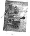
- Figure 1 illustrates a bio-concentrator and an aerosol flow switch mechanism of a biological agent detector;
- Figure 2 illustrates a front view of a pyrolyzer portion of the biological agent detector including two detectors;
- Figure 3 illustrates an enlarged front view of the pyrolyzer portion of Figure 2; and
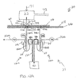
- Figures 4A and 4B illustrates movement of bio-concentrator from a first position when it aligns with one detecting device to a second position where it aligns with the other detecting device.
- Figure 1 illustrates a
bio-concentrator 22 and an aerosol flow switch mechanism 23 of abiological agent detector 20 of the present invention. Thebiological agent detector 20 detects the presence of any biological agents, such as anthrax or other biological warfare agents, in a sample of air. - The
bio-concentrator 22 concentrates an aerosol from an air stream and provides the aerosol to one detectingdevice pyrolyzer portion 21 for collection and analysis. The aerosol flow switch mechanism 23 provides the aerosol to one of the detectingdevices devices - The
bio-concentrator 22 draws over 300 liters of air per minute into thebiological agent detector 20 through an inlet 71 (shown in Figures 4A and 4B). Thebio-concentrator 22 separates aerosol particles from the main airflow and exhausts the bulk of the air through anexhaust 73 and an aligned exhaust port 95 at approximately 299 liters/minute. Thebio-concentrator 22 provides a concentrated airflow of approximately 1 liter per minute containing almost the entire aerosol of interest through a concentratedaerosol outlet 62 that leads to one of the detectingdevices - The
bio-concentrator 22 is clamped on aturntable 60 rotatable about a pivot 88. Thebio-concentrator 22 is moveable between two positions. Theconcentrated aerosol outlet 62 is alignable with one detectingdevice 26a in a first position and the other detectingdevice 26b in a second position. The air stream from theconcentrated aerosol outlet 62 flows through a small hole 110 in theturntable 60 that is aligned with theconcentrated aerosol outlet 62. Theturntable 60 rests on and is rotatable relative to a stainlesssteel base plate 66. - The
base plate 66 includes twoholes 112a and 112b that are each aligned with one of the detectingdevices turntable 60 rotates, the small hole 110 in theturntable 60 aligns with one of theholes 112a and 112b in thebase plate 66. The sidewalls of theholes 112a and 112b are polished to eliminate the possibility of discontinuities in the walls of the aerosol path. Anupper surface 118 of thebase plate 66 includes a groove that surrounds each of theholes 112a and 112b, and a rubber o-ring 114a and 114b is received in each of the grooves to provide a relatively air tight seal between theupper surface 118 of thebase plate 66 and thelower surface 116 of theturntable 60. - The
base plate 66 includes hardened steel pins that penetrate grooves in theturntable 60 to limit rotation of theturntable 60 and to provide a precise stop so that the hole 110 in theturntable 60 aligns with one of the twoholes 112a and 112b in thebase plate 66. A compression spring 72 (shown in Figures 4A and 4B) provides 10 pounds of force between theturntable 60 and thebase plate 66 to ensure that the o-rings 114a and 14b are compressed and that thelower surface 116 of theturntable 60 contacts theupper surface 118 of thebase plate 66. The precise alignment stops and the compression force ensures a smooth path for the aerosol stream with minimum discontinuities in the sidewalls of theholes 112a and 112b. - The upper surface of the
turntable 60 includes aconical alignment feature 64 feature that mates with a conical aperture 130 in the lower surface of the bio-concentrator 22 to ensure that theconcentrated aerosol outlet 62 of the bio-concentrator 22 is precisely aligned with the through hole 110 in theturntable 60. Alocking mechanism 99 locks the bio-concentrator 22 in position. - As shown in Figures 4A and 4B, a motor 70 with a reduction gearbox, a crank and a pushrod rotates the
turntable 60 approximately 180° between the first position and the second position. Micro-switches detect the position of the crank. The crank rotates to move theturntable 60 so that theconcentrator exhaust outlet 62 of the bio-concentrator 22 precisely aligns with one of the detectingdevices turntable 60 from thebase plate 66 and the o-rings 114a and 114b before theturntable 60 moves to eliminate wear on the o-rings 114a and 114b. When the hardened steel pin precision end stops prevent theturntable 60 from moving, the solenoid is deactivated and the compression spring 72 pushes theturntable 60 back down against thebase plate 66. The mechanism that switches the bio-concentrator 22 outlet aerosol flow between the two detectingdevices - Figure 2 schematically illustrates the
pyrolyzer portion 21 of thebiological agent detector 20 and an interface 22a with the bio-concentrator 22. Thepyrolyzer portion 21 includes abody portion 24 and support rods (not shown) that support thebody portion 24. Thepyrolyzer portion 21 includes the two detectingdevices devices body portion 24 includes an embedded heater andtemperature sensor device 28. Thepyrolyzer portion 21 are attached to an underside of thebase plate 66 such that themoveable bio-concentrator 22 is located above thebase plate 66. - Each detecting
device body portion 24 and can be removed for cleaning and replacement. - The sample air exits the inlet tubes 30a and 30b through an outlet 32a and 32b, respectively, and collects in a respective closed
end quartz pyrotube 34a and 34b. Thepyrotubes 34a and 34b each have a substantially conical bottom that provides a small collection volume for the sample. The diameter of the inlet tubes 30a and 30b forces approximately 1 liter per minute of aerosol flow to form a jet that impacts the internal vertex of thepyrotube 34a and 34b. The particles carried by the airflow are impacted against the internal closed end of thepyrotube 34a and 34b whereas the air is exhausted. The efficiency of particle impaction and collection requires close tolerances between the tip of the inlet tubes 30a and 30b and the bottom of thepyrotubes 34a and 34b. - Each detecting
device outlet exhaust line 36a and 36b that carries an exhaust flow at approximately 1 liter per minute. The wide diameter of theexhaust line 36a and 36b prevents fibrous and other particles that fail to impact and collect at the closed end of thepyrotube 34a and 34b from building up and clogging theexhaust lines 36a and 36b. - A injector needle 46a and 46b adds a small droplet (1 to 2 microliters) of a methylating reagent from a reagent source 44a and 44b (shown in Figures 4A and 4B) to the sample collected in the
pyrotube 34a and 34b. In one example, the methylating reagent is 0.0015 Molar to 0.015 Molar TMAH dissolved in methanol. The injector needles 46a and 46b are positioned to deliver a methylating reagent droplet to the bottom-center of therespective pyrotube 34a and 34b. The methylating reagent splits open the cells of any bacterial agents in the sample and neutralizes and derivatizes the organic molecules in the agents to more volatile compounds. The injector needles 46a and 46b are a fused quartz capillary tube. The quartz is inert and resistant to the thermal cycling of the detectingdevices - Each detecting
device body portion 24. The needle port is connected to thebody portion 24 with a thin wall of stainless steel tubing, and the needle ports are angled to provide a clear path to the bottom of thepyrotubes 34a and 34b. The tubing provides thermal resistance and allows the injector needles 46a and 46b to be maintained at a temperature lower than the temperature of thebody portion 24. The injector needles 46a and 46b do not touch the sidewalls of therespective pyrotube 34a and 34b to maintain the injector needles 46a and 46b at a lower temperature than the detectingdevices body portion 24 is hot (approximately 230°C), and the tubing keeps the needle port cool. - Each detecting
device pyrotubes 34a and 34b to amass spectrometer 40 for analysis and identification. The sample lines 38a and 38b are stainless steel and lined with a fused quartz capillary liner. The quartz provides an inert medium for the reliable transport of the pyrolysis products to themass spectrometer 40. The quartz is also resistant to the corrosive methylating reagent injected into thepyrotubes 34a and 34b during analysis. The quartz capillary liner may be positioned near the bottom of eachpyrotube 34a and 34b to maximize the collection efficiency of the pyrolysis products. - Returning to Figure 2, a spring loaded
pyrotube lifting device 48 biases thepyrotubes 34a and 34b against thebody portion 24 to prevent any clearance between atop edge 50 of thepyrotubes 34a and 34b and thebody portion 24. Pushing thepyrotubes 34a and 34b fully home ensures that the gap between the pyrolyzer internal vertex and the ends of the pyrolyzer inlet tubes 30a and 30b remains constant. Thetop edge 50 is fire-polished to reduce internal stresses to prevent fractures when pushed against thebody portion 24. - A
cylindrical vespel ferrule 52 provides a compression seal between the pyrotubes 34a and 34b and thebody portion 24. A second spring-loaded ferrule-liftingdevice 54 concentric with thepyrotube lifting device 48 applies pressure to thevespel ferrule 52 to provide a pneumatic seal. The ferrule-liftingdevice 54 operates independently of thepyrotube lifting device 48. The ferrule-liftingdevice 54 applies a greater amount of force to thevespel ferrule 52 than the pyrotube-liftingdevice 48 applies to thepyrotubes 34a and 34b. Thepyrotube lifting device 48 pushes thepyrotubes 34a and 34b against thevespel ferrule 52 to form a seal. Astep 56 around the lower edge of thevespel ferrule 52 engages a notch of the ferrule-liftingdevice 54. The ferrule-liftingdevice 54 can be lowered to remove thevespel ferrule 52 from thebiological agent detector 20. - A cylindrical heater 58a and 58b closely contoured to the bottom of the
pyrotubes 34a and 34b provides heat during pyrolysis. A blower (not shown) provides forced air-cooling through ducts at the end of pyrolysis to cool thepyrotubes 34a and 34b in preparation for the next aerosol collection cycle. - The
mass spectrometer 40 includes a preprogrammed list of molecular patterns. Each molecular pattern on the list is associated with a specific biological agent. If any biological agents are present the sample, themass spectrometer 40 identifies the biological agents by comparing the identified molecular pattern to the list of molecular patterns preprogrammed into themass spectrometer 40. After a match is found, themass spectrometer 40 identifies the associated biological agent. - One detecting
device device devices biological agent detector 20 continuously collects an air sample for analysis. The mode-switching phase lasts approximately 0.5 seconds. During the change-over period, air is still collected. Preferably, the predetermined amount of time is one minute. However, one skilled in the art would know what predetermined amount of time to employ. - As shown in Figures 4A, the detecting
device 26a operates in the sample collection mode, and the detectingdevice 26b operates in the sample analysis mode. Theconcentrated aerosol outlet 62 of the bio-concentrator 22 aligns with the detectingdevice 26a. An exhaust pump 78a draws air through the exhaust line 36a for exhausting to the atmosphere. When the exhaust pump 78a is active, the exhaust pump 78b of the detectingdevice 26b is inactive and does not exhaust air through theexhaust line 36b. The duration of the sample collection is programmable by software. In one example, the sample is collected for approximately 1 to 5 minutes. One skilled in the art would know how long to collect the sample. A control 87 controls the exhaust pumps 78a and 78b and the motor 70. - The sample lines 38a and 38b meet at a point, and an
outlet line 120 extends from the point and directly to themass spectrometer 40 to define a "T." When detectingdevice 26a is in sample collection mode and the detectingdevice 26b is in sample analysis mode, the pressure in detectingdevice 26a is lower than the ambient, and the pressure in the detectingdevice 26b is greater than the ambient. There is a net flow of gas from the detectingdevice 26b to the detectingdevice 26a. - While the detecting
device 26a is operating in the sample collection mode, a sample previously collected in the pyrotube 34b of the detectingdevice 26b is analyzed. The methylating reagent is added to the sample in the pyrotube 34b through the injector needle 46b from the reagent source 44b to split open the cells of any bacterial agents in the sample and neutralize and derivatize the organic molecules of the biological agents to form more volatile molecules. The sample in the pyrotube 34b is then pyrolyzed or heated by the heater 58b to form gas molecules. The sample can be pyrolyzed for approximately 1.5 minutes. However, one skilled in the art would know how long to pyrolyze the sample collected in the pyrotube 34b. - The pyrolysis products are directed from the detecting
device 26b and along the sample line 38b, theoutlet line 120, and directly to themass spectrometer 40. The detectingdevice 26b has an internal pressure that is greater than the internal pressure of the detectingdevice 26a, directing the pyrolysis products from the detectingdevice 26b to theoutlet line 120 and to themass spectrometer 40. Approximately 1 milliliter per minute of the gas molecules are provided to themass spectrometer 40. - After the predetermined amount of time, the detecting
devices device 26a then operates in the sample analysis mode, and the detectingdevice 26b operates in the sample collection mode. The motor 70 rotates theturntable 60 such that theconcentrated exhaust outlet 62 of the bio-concentrator 22 aligns with the inlet tube 30b of the detectingdevice 26b to collect a sample of air in the pyrotube 34b, as shown in Figure 4B. The sample of air previously collected in thepyrotube 34a of the detectingdevice 26a is then analyzed. - When the detecting
device 26b operates is in sample collection mode and the detectingdevice 26a operates in the sample analysis mode, the pressure in the detectingdevice 26b is lower than the pressure in the detectingdevice 26a. There is a net flow of gas from the detectingdevice 26a to the detectingdevice 26b. The gases from the detectingdevice 26a flows through the "T" and along theoutlet line 120 to be directly sampled by themass spectrometer 40. That is, the pyrolysis products flow along the sample line 38a and along theoutlet line 120 to themass spectrometer 40. - The
biological agent detector 20 of the present invention can be used to detect biological agents used in biological warfare, such as anthrax. However, it is to be understood that other biological agents can be detected. Any substance having a unique pattern of fatty acids that can be identified by themass spectrometer 40 can be detected and identified. - Although detecting
devices devices - The foregoing description is only exemplary of the principles of the invention. Many modifications and variations of the present invention are possible in light of the above teachings. The preferred embodiments of this invention have been disclosed, however, so that one of ordinary skill in the art would recognize that certain modifications would come within the scope of this invention. It is, therefore, to be understood that within the scope of the appended claims, the invention may be practiced otherwise than as specifically described. For that reason the following claims should be studied to determine the true scope and content of this invention.
Claims (16)
- A biological agent detection system (20) for detecting a biological agent in an air sample comprising:a first detecting device (26a); anda second detecting device (26b), wherein the first detecting device (26a) operates in a sample collection mode when the second detecting device (26b) operates in a sample analysis mode and the first detecting device (26a) operates in the sample analysis mode when the second detecting device (26b) operates in the sample collection mode.
- The system as recited in claim 1 further including a bio-concentrator (22) that concentrates the air sample to an aerosol sample, wherein the bio-concentrator is shared by the first detecting device (26a) and the second detecting device (26b).
- The system as recited in claim 2 further including a turntable (60) having a hole (110), wherein the turntable (60) moves the bio-concentrator (22) between a first position wherein the hole aligns with the first detecting device (26a) to direct the aerosol sample to the first detecting device (26a) and a second position wherein the hole aligns with the second detecting device (26b) to direct the aerosol sample to the second detecting device (26b).
- The system as recited in any preceding claim wherein each of the first detecting device (26a) and the second detecting device (26b) includes an inlet tube (30), a pyrotube (34) and a heater (58), and the inlet tube (30) draws the aerosol sample into the pyrotube (34) during the sample collection mode and the heater heats (58) an aerosol sample in the pyrotube (34) during the sample analysis mode.
- The system as recited in claim 4 wherein each of the first detecting device (26a) and the second detecting device (26b) includes a heated sample line (38) that transports the aerosol sample to a chemical analyzing device for analysis during the sample analysis mode.
- The system recited in claim 5 where the heated sample line (38) of each of the first detecting device (26a) and the second detecting device (26b) meet at a connection and a line (120) extends from the connection to the chemical analyzing device (40), wherein a pressure differential internal to the pyrotube (34) of each of the first detecting device (26a) and the second detecting device (26b) causes a net flow of pyrolysis gas products from one of the first detecting device (26a) and the second detecting device (26b) that is operating in the sample analysis mode to the other of the first detecting device (26a) and the second detecting device (26b) that is operating in the sample collection mode and directs the aerosol sample in the one of the first detecting device (26a) and the second detecting device (26b) that is operating in the sample analysis mode to the chemical analysis device (40).
- The system as recited in any of claims 4, 5 or 6 further including a reagent source (44) that contains a methylating reagent, wherein each of the first detecting device (26a) and the second detecting device (26b) includes an injector needle (46) that injects the methylating reagent into the pyrotube (34) during the sample analysis mode.
- The system as recited in any of claims 4 to 7 further including a lifting device (48) that biases the pyrotube (34) against a body portion (24) to ensure a gap between a closed end of the pyrotube (34) and the inlet tube (30) is constant.
- The system as recited in any of claims 4 to 8 further including a vespel ferrule (52), a body portion (24) and a lifting device (54) that biases the vespel ferrule (52) against the body portion (24) to form a seal that contains the aerosol sample and processed gasses in the pyrotube (34).
- The system as recited in any preceding claim wherein each of the first detecting device (26a) and the second detecting device (26b) includes an exhaust line (36), wherein a portion of the air sample drawn into one of the first detecting device (26a) and the second detecting device (26b) during the sample collection mode is exhausted through the exhaust line (36).
- A biological agent detection system (20) for detecting a biological agent in an air sample comprising:a bio-concentrator (22) that concentrates the air sample to an aerosol sample;a detecting device including:a first detecting device (26a) including a first inlet tube (30a) that draws the aerosol sample into a first pyrotube (34a) when the first detecting device (26a) is operating in a sample collection mode, a first injector needle (46a) and a first sample line, anda second detecting device (26b) including a second inlet tube (30b) that draws the aerosol sample into a second pyrotube (34b) when the second detecting device (26b) is operating in the sample collection mode, a second injector needle (46b), and a second sample line, wherein the first detecting device (26a) operates in the sample collection mode when the second detecting device (26b)s operates in a sample analysis mode and the first detecting device (26a) operates in the sample analysis mode when the second detecting device (26b)s operates in the sample collection mode;a heater (58a, 58b) to heat the aerosol sample collected in the first pyrotube (34a) and the second pyrotube (34b) during the sample analysis mode;a reagent source (44a, 44b) that contains a methylating reagent, wherein each of the first injector needle (46a) and the second injector needle (46b) injects the methylating reagent into the first pyrotube (34a) and the second pyrotube (34b), respectively, during the sample analysis mode; anda mass spectrometer (40) for identification of any biological agents in the aerosol sample during the sample analysis mode.
- The system as recited in claim 11 further including a turntable (60) having a hole (110), wherein the turntable (60) moves the bio-concentrator (22) between a first position wherein the hole aligns with the first detecting device (26a) to direct the aerosol sample to the first detecting device (26a) and a second position wherein the hole aligns with the second detecting device (26b) to direct the aerosol sample to the second detecting device (26b).
- The system as recited in claim 11 or 12 wherein each of the first detecting device (26a) and the second detecting device (26b) includes an exhaust line (36), wherein a portion of the air sample drawn into one of the first detecting device (26a) and the second detecting device (26b) during the sample collection mode is exhausted through the exhaust line (36).
- A method of detecting a biological agent in an air sample comprising the steps of:flowing a first aerosol sample into a first detecting device (26a) during a sample collection mode;identifying any biological agents in a second aerosol sample collected in a second detecting device (26b) during a sample analysis mode, wherein the step of identifying the biological agents in the second aerosol sample occurs during the step of flowing the first aerosol sample;then flowing a third aerosol sample into the second detecting device (26b); andidentifying the biological agents in the first aerosol sample collected in the first detecting device (26a), wherein the step of identifying the biological agents in the first air sample occurs during the step of then flowing the third aerosol sample.
- The method as recited in claim 14 wherein the steps of identifying the biological agents includes adding a methylating reagent and heating the first aerosol sample and heating the third aerosol sample.
- The method as recited in claim 14 further including the step of concentrating the air sample into the first aerosol sample and the third aerosol sample prior to the steps of flowing the first aerosol sample into the first detecting device (26a) and flowing the third aerosol sample into the second detecting device (26b), respectively.
Applications Claiming Priority (1)
| Application Number | Priority Date | Filing Date | Title |
|---|---|---|---|
| US58690204P | 2004-07-09 | 2004-07-09 |
Publications (2)
| Publication Number | Publication Date |
|---|---|
| EP1615015A1 true EP1615015A1 (en) | 2006-01-11 |
| EP1615015B1 EP1615015B1 (en) | 2016-12-21 |
Family
ID=35079212
Family Applications (1)
| Application Number | Title | Priority Date | Filing Date |
|---|---|---|---|
| EP05254341.0A Expired - Lifetime EP1615015B1 (en) | 2004-07-09 | 2005-07-11 | Biological agent detector |
Country Status (3)
| Country | Link |
|---|---|
| US (2) | US7837937B2 (en) |
| EP (1) | EP1615015B1 (en) |
| JP (1) | JP4384624B2 (en) |
Families Citing this family (6)
| Publication number | Priority date | Publication date | Assignee | Title |
|---|---|---|---|---|
| US9544612B2 (en) | 2012-10-04 | 2017-01-10 | Intel Corporation | Prediction parameter inheritance for 3D video coding |
| KR101279035B1 (en) | 2012-12-20 | 2013-07-05 | 국방과학연구소 | Pyrolysis unit for pyrolysis apparatus for organic matter and control method thereof |
| US9726653B2 (en) | 2014-03-26 | 2017-08-08 | Hamilton Sundstrand Corporation | Chemical detector |
| CN104483423B (en) * | 2014-12-31 | 2016-03-09 | 同方威视技术股份有限公司 | Sample collection and thermal desorption sampling device and method and trace detection equipment |
| CN104569228B (en) * | 2014-12-31 | 2016-03-16 | 同方威视技术股份有限公司 | A kind of sampling device |
| US11609008B2 (en) | 2020-06-26 | 2023-03-21 | Hamilton Sundstrand Corporation | Detection and automatic response to biological hazards in critical infrastructure |
Citations (5)
| Publication number | Priority date | Publication date | Assignee | Title |
|---|---|---|---|---|
| US3754868A (en) | 1970-07-06 | 1973-08-28 | Aerojet General Co | Device for preparation of sample for biological agent detector |
| EP0447158A2 (en) | 1990-03-13 | 1991-09-18 | Her Majesty The Queen In Right Of Canada As Represented By The Minister Of Revenue | Detector for concealed explosive or narcotic substances |
| WO2002029380A2 (en) * | 2000-10-04 | 2002-04-11 | The Secretary Of State For Defence | Air samplers |
| DE10211655A1 (en) * | 2002-03-15 | 2003-10-02 | Manfred Baumgaertner | Sensor to register air contamination by biological weapons has a particle sorting stage, a pyrolysis unit and a separator for sample identification, and a pyrolysis bypass for testing chemical weapons |
| WO2003100382A1 (en) * | 2002-05-20 | 2003-12-04 | Northrop Grumman Corporation | Automatic point source biological agent detection system |
Family Cites Families (2)
| Publication number | Priority date | Publication date | Assignee | Title |
|---|---|---|---|---|
| NL1016887C2 (en) | 2000-12-15 | 2002-06-18 | Tno | Method and device for detecting and identifying bio-aerosol particles in the air. |
| US7265669B2 (en) * | 2004-03-01 | 2007-09-04 | Mesosystems Technology, Inc. | Networks with sensors for air safety and security |
-
2005
- 2005-07-05 US US11/174,925 patent/US7837937B2/en not_active Expired - Fee Related
- 2005-07-11 JP JP2005201147A patent/JP4384624B2/en not_active Expired - Fee Related
- 2005-07-11 EP EP05254341.0A patent/EP1615015B1/en not_active Expired - Lifetime
-
2010
- 2010-11-16 US US12/947,026 patent/US7977113B2/en not_active Expired - Fee Related
Patent Citations (5)
| Publication number | Priority date | Publication date | Assignee | Title |
|---|---|---|---|---|
| US3754868A (en) | 1970-07-06 | 1973-08-28 | Aerojet General Co | Device for preparation of sample for biological agent detector |
| EP0447158A2 (en) | 1990-03-13 | 1991-09-18 | Her Majesty The Queen In Right Of Canada As Represented By The Minister Of Revenue | Detector for concealed explosive or narcotic substances |
| WO2002029380A2 (en) * | 2000-10-04 | 2002-04-11 | The Secretary Of State For Defence | Air samplers |
| DE10211655A1 (en) * | 2002-03-15 | 2003-10-02 | Manfred Baumgaertner | Sensor to register air contamination by biological weapons has a particle sorting stage, a pyrolysis unit and a separator for sample identification, and a pyrolysis bypass for testing chemical weapons |
| WO2003100382A1 (en) * | 2002-05-20 | 2003-12-04 | Northrop Grumman Corporation | Automatic point source biological agent detection system |
Also Published As
| Publication number | Publication date |
|---|---|
| EP1615015B1 (en) | 2016-12-21 |
| US7837937B2 (en) | 2010-11-23 |
| US20110061447A1 (en) | 2011-03-17 |
| US7977113B2 (en) | 2011-07-12 |
| US20070189929A1 (en) | 2007-08-16 |
| JP4384624B2 (en) | 2009-12-16 |
| JP2006023310A (en) | 2006-01-26 |
Similar Documents
| Publication | Publication Date | Title |
|---|---|---|
| US7977113B2 (en) | Biological agent detector method | |
| AU2003285852B2 (en) | Point source biological agent detection system | |
| US5352611A (en) | Method and system for sampling and determining the presence of compounds in containers | |
| US7275453B2 (en) | Analyzing apparatus and fine particle collecting apparatus | |
| US9696288B2 (en) | Attached matter testing device and testing method | |
| EP2296167A1 (en) | Ion source, mass spectrometer, detector and monitoring system | |
| EP1322934B1 (en) | Sampler for collecting particles from air | |
| KR102179129B1 (en) | An apparatus for integrated measuring stationary sources of stack exhaust gas | |
| US7339165B2 (en) | Dual outlet pyrolyzer for biological agent detection system | |
| US5983732A (en) | Integrated collection and vaporization particle chemistry monitoring | |
| CN114072679A (en) | Automatic analyzer | |
| US8217339B2 (en) | Adhering matter inspection equipment and method for inspecting adhering method | |
| CN214150548U (en) | Double-channel portable organic pollutant detector | |
| CN109470547B (en) | A gradient thermal analysis injector | |
| CN112345490A (en) | Method for controlling a furnace and analytical device for carrying out the method | |
| US5493890A (en) | Apparatus and method for calibrating vapor/particle detection devices | |
| JP4054493B2 (en) | Ion source | |
| US12531224B2 (en) | High flowrate flushing for open port sampling probe | |
| WO2022167917A1 (en) | Methods and apparatus for washing sampling probe for use in mass spectrometry systems | |
| CN113945431A (en) | Trace substance sampling device, analysis system and sampling method | |
| JP2006258462A (en) | Gas analyzer | |
| US20250343035A1 (en) | Pressure Based OPI Position Control | |
| CN117178191A (en) | Systems and methods for humidity and/or temperature control in sample analysis systems | |
| US20230170202A1 (en) | Detecting chemical compounds for forensic analysis | |
| WO2022113053A1 (en) | Sampling system for an open port probe |
Legal Events
| Date | Code | Title | Description |
|---|---|---|---|
| PUAI | Public reference made under article 153(3) epc to a published international application that has entered the european phase |
Free format text: ORIGINAL CODE: 0009012 |
|
| AK | Designated contracting states |
Kind code of ref document: A1 Designated state(s): AT BE BG CH CY CZ DE DK EE ES FI FR GB GR HU IE IS IT LI LT LU LV MC NL PL PT RO SE SI SK TR |
|
| AX | Request for extension of the european patent |
Extension state: AL BA HR MK YU |
|
| 17P | Request for examination filed |
Effective date: 20060216 |
|
| AKX | Designation fees paid |
Designated state(s): AT BE BG CH CY CZ DE DK EE ES FI FR GB GR HU IE IS IT LI LT LU LV MC NL PL PT RO SE SI SK TR |
|
| GRAP | Despatch of communication of intention to grant a patent |
Free format text: ORIGINAL CODE: EPIDOSNIGR1 |
|
| INTG | Intention to grant announced |
Effective date: 20160802 |
|
| GRAS | Grant fee paid |
Free format text: ORIGINAL CODE: EPIDOSNIGR3 |
|
| GRAA | (expected) grant |
Free format text: ORIGINAL CODE: 0009210 |
|
| AK | Designated contracting states |
Kind code of ref document: B1 Designated state(s): AT BE BG CH CY CZ DE DK EE ES FI FR GB GR HU IE IS IT LI LT LU LV MC NL PL PT RO SE SI SK TR |
|
| REG | Reference to a national code |
Ref country code: GB Ref legal event code: FG4D |
|
| REG | Reference to a national code |
Ref country code: CH Ref legal event code: EP |
|
| REG | Reference to a national code |
Ref country code: IE Ref legal event code: FG4D |
|
| REG | Reference to a national code |
Ref country code: AT Ref legal event code: REF Ref document number: 855895 Country of ref document: AT Kind code of ref document: T Effective date: 20170115 |
|
| REG | Reference to a national code |
Ref country code: DE Ref legal event code: R096 Ref document number: 602005050941 Country of ref document: DE |
|
| PG25 | Lapsed in a contracting state [announced via postgrant information from national office to epo] |
Ref country code: LV Free format text: LAPSE BECAUSE OF FAILURE TO SUBMIT A TRANSLATION OF THE DESCRIPTION OR TO PAY THE FEE WITHIN THE PRESCRIBED TIME-LIMIT Effective date: 20161221 |
|
| REG | Reference to a national code |
Ref country code: LT Ref legal event code: MG4D |
|
| REG | Reference to a national code |
Ref country code: NL Ref legal event code: MP Effective date: 20161221 |
|
| PG25 | Lapsed in a contracting state [announced via postgrant information from national office to epo] |
Ref country code: GR Free format text: LAPSE BECAUSE OF FAILURE TO SUBMIT A TRANSLATION OF THE DESCRIPTION OR TO PAY THE FEE WITHIN THE PRESCRIBED TIME-LIMIT Effective date: 20170322 Ref country code: SE Free format text: LAPSE BECAUSE OF FAILURE TO SUBMIT A TRANSLATION OF THE DESCRIPTION OR TO PAY THE FEE WITHIN THE PRESCRIBED TIME-LIMIT Effective date: 20161221 Ref country code: LT Free format text: LAPSE BECAUSE OF FAILURE TO SUBMIT A TRANSLATION OF THE DESCRIPTION OR TO PAY THE FEE WITHIN THE PRESCRIBED TIME-LIMIT Effective date: 20161221 |
|
| REG | Reference to a national code |
Ref country code: AT Ref legal event code: MK05 Ref document number: 855895 Country of ref document: AT Kind code of ref document: T Effective date: 20161221 |
|
| PG25 | Lapsed in a contracting state [announced via postgrant information from national office to epo] |
Ref country code: FI Free format text: LAPSE BECAUSE OF FAILURE TO SUBMIT A TRANSLATION OF THE DESCRIPTION OR TO PAY THE FEE WITHIN THE PRESCRIBED TIME-LIMIT Effective date: 20161221 |
|
| PG25 | Lapsed in a contracting state [announced via postgrant information from national office to epo] |
Ref country code: NL Free format text: LAPSE BECAUSE OF FAILURE TO SUBMIT A TRANSLATION OF THE DESCRIPTION OR TO PAY THE FEE WITHIN THE PRESCRIBED TIME-LIMIT Effective date: 20161221 |
|
| PG25 | Lapsed in a contracting state [announced via postgrant information from national office to epo] |
Ref country code: RO Free format text: LAPSE BECAUSE OF FAILURE TO SUBMIT A TRANSLATION OF THE DESCRIPTION OR TO PAY THE FEE WITHIN THE PRESCRIBED TIME-LIMIT Effective date: 20161221 Ref country code: SK Free format text: LAPSE BECAUSE OF FAILURE TO SUBMIT A TRANSLATION OF THE DESCRIPTION OR TO PAY THE FEE WITHIN THE PRESCRIBED TIME-LIMIT Effective date: 20161221 Ref country code: IS Free format text: LAPSE BECAUSE OF FAILURE TO SUBMIT A TRANSLATION OF THE DESCRIPTION OR TO PAY THE FEE WITHIN THE PRESCRIBED TIME-LIMIT Effective date: 20170421 Ref country code: CZ Free format text: LAPSE BECAUSE OF FAILURE TO SUBMIT A TRANSLATION OF THE DESCRIPTION OR TO PAY THE FEE WITHIN THE PRESCRIBED TIME-LIMIT Effective date: 20161221 Ref country code: EE Free format text: LAPSE BECAUSE OF FAILURE TO SUBMIT A TRANSLATION OF THE DESCRIPTION OR TO PAY THE FEE WITHIN THE PRESCRIBED TIME-LIMIT Effective date: 20161221 |
|
| PG25 | Lapsed in a contracting state [announced via postgrant information from national office to epo] |
Ref country code: PL Free format text: LAPSE BECAUSE OF FAILURE TO SUBMIT A TRANSLATION OF THE DESCRIPTION OR TO PAY THE FEE WITHIN THE PRESCRIBED TIME-LIMIT Effective date: 20161221 Ref country code: IT Free format text: LAPSE BECAUSE OF FAILURE TO SUBMIT A TRANSLATION OF THE DESCRIPTION OR TO PAY THE FEE WITHIN THE PRESCRIBED TIME-LIMIT Effective date: 20161221 Ref country code: BG Free format text: LAPSE BECAUSE OF FAILURE TO SUBMIT A TRANSLATION OF THE DESCRIPTION OR TO PAY THE FEE WITHIN THE PRESCRIBED TIME-LIMIT Effective date: 20170321 Ref country code: AT Free format text: LAPSE BECAUSE OF FAILURE TO SUBMIT A TRANSLATION OF THE DESCRIPTION OR TO PAY THE FEE WITHIN THE PRESCRIBED TIME-LIMIT Effective date: 20161221 Ref country code: BE Free format text: LAPSE BECAUSE OF FAILURE TO SUBMIT A TRANSLATION OF THE DESCRIPTION OR TO PAY THE FEE WITHIN THE PRESCRIBED TIME-LIMIT Effective date: 20161221 Ref country code: ES Free format text: LAPSE BECAUSE OF FAILURE TO SUBMIT A TRANSLATION OF THE DESCRIPTION OR TO PAY THE FEE WITHIN THE PRESCRIBED TIME-LIMIT Effective date: 20161221 Ref country code: PT Free format text: LAPSE BECAUSE OF FAILURE TO SUBMIT A TRANSLATION OF THE DESCRIPTION OR TO PAY THE FEE WITHIN THE PRESCRIBED TIME-LIMIT Effective date: 20170421 |
|
| REG | Reference to a national code |
Ref country code: DE Ref legal event code: R097 Ref document number: 602005050941 Country of ref document: DE |
|
| PLBE | No opposition filed within time limit |
Free format text: ORIGINAL CODE: 0009261 |
|
| STAA | Information on the status of an ep patent application or granted ep patent |
Free format text: STATUS: NO OPPOSITION FILED WITHIN TIME LIMIT |
|
| 26N | No opposition filed |
Effective date: 20170922 |
|
| PG25 | Lapsed in a contracting state [announced via postgrant information from national office to epo] |
Ref country code: DK Free format text: LAPSE BECAUSE OF FAILURE TO SUBMIT A TRANSLATION OF THE DESCRIPTION OR TO PAY THE FEE WITHIN THE PRESCRIBED TIME-LIMIT Effective date: 20161221 |
|
| PG25 | Lapsed in a contracting state [announced via postgrant information from national office to epo] |
Ref country code: SI Free format text: LAPSE BECAUSE OF FAILURE TO SUBMIT A TRANSLATION OF THE DESCRIPTION OR TO PAY THE FEE WITHIN THE PRESCRIBED TIME-LIMIT Effective date: 20161221 |
|
| REG | Reference to a national code |
Ref country code: CH Ref legal event code: PL |
|
| REG | Reference to a national code |
Ref country code: IE Ref legal event code: MM4A |
|
| REG | Reference to a national code |
Ref country code: FR Ref legal event code: ST Effective date: 20180330 |
|
| PG25 | Lapsed in a contracting state [announced via postgrant information from national office to epo] |
Ref country code: LI Free format text: LAPSE BECAUSE OF NON-PAYMENT OF DUE FEES Effective date: 20170731 Ref country code: IE Free format text: LAPSE BECAUSE OF NON-PAYMENT OF DUE FEES Effective date: 20170711 Ref country code: CH Free format text: LAPSE BECAUSE OF NON-PAYMENT OF DUE FEES Effective date: 20170731 |
|
| PG25 | Lapsed in a contracting state [announced via postgrant information from national office to epo] |
Ref country code: FR Free format text: LAPSE BECAUSE OF NON-PAYMENT OF DUE FEES Effective date: 20170731 |
|
| PG25 | Lapsed in a contracting state [announced via postgrant information from national office to epo] |
Ref country code: LU Free format text: LAPSE BECAUSE OF NON-PAYMENT OF DUE FEES Effective date: 20170711 |
|
| PG25 | Lapsed in a contracting state [announced via postgrant information from national office to epo] |
Ref country code: HU Free format text: LAPSE BECAUSE OF FAILURE TO SUBMIT A TRANSLATION OF THE DESCRIPTION OR TO PAY THE FEE WITHIN THE PRESCRIBED TIME-LIMIT; INVALID AB INITIO Effective date: 20050711 Ref country code: MC Free format text: LAPSE BECAUSE OF FAILURE TO SUBMIT A TRANSLATION OF THE DESCRIPTION OR TO PAY THE FEE WITHIN THE PRESCRIBED TIME-LIMIT Effective date: 20161221 |
|
| PG25 | Lapsed in a contracting state [announced via postgrant information from national office to epo] |
Ref country code: CY Free format text: LAPSE BECAUSE OF NON-PAYMENT OF DUE FEES Effective date: 20161221 |
|
| PG25 | Lapsed in a contracting state [announced via postgrant information from national office to epo] |
Ref country code: TR Free format text: LAPSE BECAUSE OF FAILURE TO SUBMIT A TRANSLATION OF THE DESCRIPTION OR TO PAY THE FEE WITHIN THE PRESCRIBED TIME-LIMIT Effective date: 20161221 |
|
| PGFP | Annual fee paid to national office [announced via postgrant information from national office to epo] |
Ref country code: GB Payment date: 20200624 Year of fee payment: 16 |
|
| PGFP | Annual fee paid to national office [announced via postgrant information from national office to epo] |
Ref country code: DE Payment date: 20200622 Year of fee payment: 16 |
|
| REG | Reference to a national code |
Ref country code: DE Ref legal event code: R082 Ref document number: 602005050941 Country of ref document: DE |
|
| REG | Reference to a national code |
Ref country code: DE Ref legal event code: R119 Ref document number: 602005050941 Country of ref document: DE |
|
| GBPC | Gb: european patent ceased through non-payment of renewal fee |
Effective date: 20210711 |
|
| PG25 | Lapsed in a contracting state [announced via postgrant information from national office to epo] |
Ref country code: GB Free format text: LAPSE BECAUSE OF NON-PAYMENT OF DUE FEES Effective date: 20210711 Ref country code: DE Free format text: LAPSE BECAUSE OF NON-PAYMENT OF DUE FEES Effective date: 20220201 |