EP1614890A1 - Fuel feed device - Google Patents
Fuel feed device Download PDFInfo
- Publication number
- EP1614890A1 EP1614890A1 EP04726813A EP04726813A EP1614890A1 EP 1614890 A1 EP1614890 A1 EP 1614890A1 EP 04726813 A EP04726813 A EP 04726813A EP 04726813 A EP04726813 A EP 04726813A EP 1614890 A1 EP1614890 A1 EP 1614890A1
- Authority
- EP
- European Patent Office
- Prior art keywords
- fuel
- plunger
- eject
- vapor
- supply apparatus
- Prior art date
- Legal status (The legal status is an assumption and is not a legal conclusion. Google has not performed a legal analysis and makes no representation as to the accuracy of the status listed.)
- Withdrawn
Links
Images



Classifications
-
- F—MECHANICAL ENGINEERING; LIGHTING; HEATING; WEAPONS; BLASTING
- F04—POSITIVE - DISPLACEMENT MACHINES FOR LIQUIDS; PUMPS FOR LIQUIDS OR ELASTIC FLUIDS
- F04B—POSITIVE-DISPLACEMENT MACHINES FOR LIQUIDS; PUMPS
- F04B17/00—Pumps characterised by combination with, or adaptation to, specific driving engines or motors
- F04B17/03—Pumps characterised by combination with, or adaptation to, specific driving engines or motors driven by electric motors
- F04B17/04—Pumps characterised by combination with, or adaptation to, specific driving engines or motors driven by electric motors using solenoids
- F04B17/042—Pumps characterised by combination with, or adaptation to, specific driving engines or motors driven by electric motors using solenoids the solenoid motor being separated from the fluid flow
- F04B17/044—Pumps characterised by combination with, or adaptation to, specific driving engines or motors driven by electric motors using solenoids the solenoid motor being separated from the fluid flow using solenoids directly actuating the piston
-
- F—MECHANICAL ENGINEERING; LIGHTING; HEATING; WEAPONS; BLASTING
- F02—COMBUSTION ENGINES; HOT-GAS OR COMBUSTION-PRODUCT ENGINE PLANTS
- F02M—SUPPLYING COMBUSTION ENGINES IN GENERAL WITH COMBUSTIBLE MIXTURES OR CONSTITUENTS THEREOF
- F02M37/00—Apparatus or systems for feeding liquid fuel from storage containers to carburettors or fuel-injection apparatus; Arrangements for purifying liquid fuel specially adapted for, or arranged on, internal-combustion engines
- F02M37/04—Feeding by means of driven pumps
- F02M37/08—Feeding by means of driven pumps electrically driven
-
- F—MECHANICAL ENGINEERING; LIGHTING; HEATING; WEAPONS; BLASTING
- F02—COMBUSTION ENGINES; HOT-GAS OR COMBUSTION-PRODUCT ENGINE PLANTS
- F02M—SUPPLYING COMBUSTION ENGINES IN GENERAL WITH COMBUSTIBLE MIXTURES OR CONSTITUENTS THEREOF
- F02M37/00—Apparatus or systems for feeding liquid fuel from storage containers to carburettors or fuel-injection apparatus; Arrangements for purifying liquid fuel specially adapted for, or arranged on, internal-combustion engines
- F02M37/20—Apparatus or systems for feeding liquid fuel from storage containers to carburettors or fuel-injection apparatus; Arrangements for purifying liquid fuel specially adapted for, or arranged on, internal-combustion engines characterised by means for preventing vapour lock
-
- F—MECHANICAL ENGINEERING; LIGHTING; HEATING; WEAPONS; BLASTING
- F02—COMBUSTION ENGINES; HOT-GAS OR COMBUSTION-PRODUCT ENGINE PLANTS
- F02M—SUPPLYING COMBUSTION ENGINES IN GENERAL WITH COMBUSTIBLE MIXTURES OR CONSTITUENTS THEREOF
- F02M37/00—Apparatus or systems for feeding liquid fuel from storage containers to carburettors or fuel-injection apparatus; Arrangements for purifying liquid fuel specially adapted for, or arranged on, internal-combustion engines
- F02M37/22—Arrangements for purifying liquid fuel specially adapted for, or arranged on, internal-combustion engines, e.g. arrangements in the feeding system
- F02M37/32—Arrangements for purifying liquid fuel specially adapted for, or arranged on, internal-combustion engines, e.g. arrangements in the feeding system characterised by filters or filter arrangements
- F02M37/44—Filters structurally associated with pumps
-
- F—MECHANICAL ENGINEERING; LIGHTING; HEATING; WEAPONS; BLASTING
- F04—POSITIVE - DISPLACEMENT MACHINES FOR LIQUIDS; PUMPS FOR LIQUIDS OR ELASTIC FLUIDS
- F04B—POSITIVE-DISPLACEMENT MACHINES FOR LIQUIDS; PUMPS
- F04B17/00—Pumps characterised by combination with, or adaptation to, specific driving engines or motors
- F04B17/03—Pumps characterised by combination with, or adaptation to, specific driving engines or motors driven by electric motors
- F04B17/04—Pumps characterised by combination with, or adaptation to, specific driving engines or motors driven by electric motors using solenoids
- F04B17/048—Pumps characterised by combination with, or adaptation to, specific driving engines or motors driven by electric motors using solenoids the fluid flowing around the moving part of the motor
Definitions
- the present invention relates to a fuel supply apparatus which comprises an electromagnetically driven type plunger pump. More particularly, it relates to a fuel supply apparatus which is utilized to supply fuel to an engine, a heater for a vehicle, or the like.
- a fuel supply apparatus which supplies fuel to a burner for a heater etc. is known, in which the fuel in a fuel tank 1 is introduced to a filter unit 3 through a feed pipe 2, and the filtered fuel is supplied to the burner 5 by being sucked and pressure fed with an electromagnetically driven type plunger pump 4, as shown in Fig. 5.
- the plunger pump 4 comprises a plunger 4b which reciprocates in a cylinder 4a, a coil 4c for magnetizing, a yoke 4d, and a coil spring (not shown in the figure) which urges the plunger 4a.
- the plunger pump 4 sucks and discharges fuel by opening and closing a check-valve with pressure difference between rooms on both sides of the plunger 4b.
- Japanese Patent Laid-open H11-218076 shows an example.
- the vapor is generated continuously, while some generated vapor is returned to the fuel tank 1 through the feed pipe 2, the rest is sucked into a pump room and discharged mixing with fuel. As a consequence, especially when the ambient temperature or the fuel temperature is high, the discharge amount or the discharge pressure is not obtained as desired, and the fuel cannot be supplied reliably.
- the present invention was devised in the light of the abovementioned circumstances.
- the object is to provide a fuel supply apparatus which has a better pump discharge performance especially at high temperature, by ejecting generated vapor efficiently or by cooling the fuel utilizing the generated vapor.
- the fuel supply apparatus of the present invention comprises a filter which filters fuel introduced from a fuel tank, a plunger which reciprocates in a specific direction by electromagnetic force, a cylindrical body which accommodates the plunger to be free to reciprocate and which forms a pump room, a plunger pump which sucks and discharges fuel having an inlet valve to allow sucking of fuel to the pump room and an outlet valve to allow discharging of fuel from the pump room, a fuel store portion which is integrally disposed to the plunger pump to store fuel tentatively at the upstream side of the inlet valve, and an eject passage which is disposed between the cylindrical body and the fuel store portion to eject fuel leaking through the circumference of the plunger or generated vapor.
- the fuel filtered by the filter is tentatively stored at the fuel store portion, and then, is sucked into the pump room through the inlet valve and discharged through the outlet valve by the reciprocating motion of the plunger. At that time, the fuel leaking through the circumference of the plunger to the other end side room of the plunger or the generated vapor is ejected to the fuel store portion through the eject passage. In this manner, vapor can be prevented from being discharged with fuel, and the fuel in the fuel store portion can be cooled by the vapor, so that the discharge performance of the pump, especially at high temperature, can be improved.
- the fuel store portion is formed integrally to the plunger pump, the fuel cooled by the vapor can be quickly introduced to a pump room, while suppressing influence of ambient conditions as much as possible.
- the cylindrical body prefferably comprises an inlet port which is formed facing one end side of the plunger to be opened and closed by the inlet valve, an eject port which is formed facing the other end side of the plunger to communicate with the eject passage, and an outlet port which is formed at the inner wall of the pump room to be opened and closed by the outlet valve.
- the filter can be disposed in the fuel store portion, and the fuel store portion can comprise an opening portion which connects the eject passage at the upstream side of the filter.
- the apparatus can be simplified. Further, the fuel leaking in the cylindrical body and the generated vapor flow into the fuel store portion from the opening portion which positions at the upstream side of the filter. Then, the fuel is sucked after being filtered again by the filter, and the generated vapor cools fuel with its vaporization and is ejected towards the fuel tank with its buoyancy.
- scattering means can be disposed at the opening portion to scatter vapor which is flowing through the eject passage.
- a mesh-shaped filter can be adopted as the scattering means.
- the vapor passing through the eject passage is scattered (crushed) by the mesh-shaped filter. Further, at a non-operating state, it can prevent motes such as foreign particles etc. mixed into the fuel tank from flowing into the eject passage through the opening portion.
- a pressure regulator to adjust the pressure of discharged fuel can be integrally disposed to the plunger pump.
- Fig. 1 is a system diagram of when the apparatus is utilized for an engine.
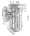
- Fig. 2 is a sectional view showing the structure of the apparatus.
- Fig. 3 is a sectional view showing a part of the apparatus.
- Fig. 4 is a schematic drawing to explain the functions of the apparatus.
- the system comprises a fuel tank 10, an injector 20 which injects fuel to an engine E located below the fuel tank 10, feed pipes 30, 30' which connect the fuel tank 10 and the injector 20, a fuel supply apparatus 100 which positions at some midpoint of the feed pipes 30, 30', a control circuit 200 which controls the system, and so on.
- the fuel supply apparatus 100 comprises a plunger pump 110 which sucks and discharges fuel, a fuel store portion 150 which tentatively stores fuel, an eject pipe 170 which ejects leaked fuel and vapor towards the fuel store portion 150, an inlet control type pressure regulator 180 which controls fuel pressure, and so on.
- the apparatus 100 is modularized to comprise the plunger pump 110, the fuel store portion 150, the eject pipe 170, and the pressure regulator 180 integrally, downsizing altogether and simplifying the structure can be performed, and in-line installation can easily be adopted.
- the plunger pump 110 is a positive displacement pump which is driven electromagnetically. As shown in Fig. 1 and Fig. 2, it comprises a cylinder 111 which forms a part of a cylindrical body, a cylinder-shaped plunger 112 which is disposed to reciprocate linearly sliding in the cylinder 111, yokes 113, 114 which are fit to the circumference of the cylinder 111 to form a magnetic path, a coil 116 for magnetizing which is wound around a bobbin 115 disposed around the yokes 113, 114, a case 117 which is formed of resin material etc.
- a bracket 118 and a stop plate 119 which are attached around the case 117 to form a magnetic path
- a waved washer 120 which is disposed between the bobbin 115 and the bracket 118, and so on.
- an end face wall 113a is formed at the end portion of the yoke 113 which forms the end portion of the cylindrical body.
- a fit opening 113a' is formed at the end face wall 113a, and a connect pipe 121 which forms an eject port 121a is connected to the fit opening 113a'.
- a return spring 122 is disposed between the end face wall 113a and the plunger 112.
- a passage member 123 which forms an inlet port 123a and a part of the cylindrical body is fitted to the end portion of the yoke 114.
- the passage member 123 has a hold member 125 which allows the fuel to flow while holding an inlet valve 124 which opens and closes the inlet port 123a.
- the hold member 125 holds the inlet valve 124 at the state of being urged to the closing direction by a spring 124a.
- a return spring 122 is disposed between the hold member 125 and the plunger 112.
- the inlet port 123a which is opened and closed by the inlet valve 124 is formed at the position facing one end side of the plunger 112
- the eject port 121a which communicates with an eject passage 170a (described later) is formed at the position facing the other end side of the plunger 112.
- An outlet port 126a which is opened and closed by an outlet valve 127 is formed at the inner wall of the pump room P.
- an outlet passage 126 which forms the outlet port 126a and extends in the direction perpendicular to the reciprocating direction of the plunger 112 is formed at the inner wall of the passage member 123.
- a hold member 128 which holds the outlet valve 127 to open and close the outlet port 126a and which allows the fuel to flow is disposed in the outlet passage 126.
- the holding member 128 holds the outlet valve 127 at the state being urged to the closing direction by the spring 127a.
- the fuel store portion 150 comprises a case 151 which is fitted to the passage member 123 at the upstream side next to the inlet valve 124 and which has an opening portion 151a connected to the inlet port 123a, a mesh-shaped filter 152 which is disposed in the case 151 to cover the opening portion 151a and which has a vapor eject vale 152a, a connect pipe 151b which is disposed at the top end of the case 151 and to which a feed pipe 30 is connected, a connect pipe 151c which is disposed at the upper side-wall of the case 151 and which forms an opening portion 151c', a mesh-shaped filter 155 as scattering means which is disposed above the filter 152 to cover the opening portion 151c', and so on.
- an eject pipe 170 is connected to both the connect pipe 120 and the connect pipe 151c.
- the eject pipe 170 forms the eject passage 170a which ejects the fuel leaking through the circumference of the plunger 112 or generated vapor towards the fuel store portion 150 (the case 151).
- the fuel leaking through the circumference of the plunger 112 and the generated vapor flow into the case 151 from the opening portion 151c' which positions at the upstream side of the filter 152, passing through the eject port 121a and the eject passage 170a. Then, the fuel is sucked to the pump room P after being filtered again by the filter 152. On the other hand, the generated vapor cools fuel with its vaporization, and is ejected to the fuel tank 10 with its buoyancy passing through the feed pipe 30.
- the filter 155 can prevent motes such as foreign particles etc. mixed into the fuel tank 10 from flowing into the eject passage 170a through the opening portion 151c'.
- the regulator 180 comprises an adjust valve 182 which opens and closes the passage 181 at the downstream side of the outlet valve 127, a spring 182a which urges the adjust valve 182 in the closing direction, a diaphragm 184 which is operated by the pressure difference between the atmospheric pressure and the pressure in the passage 183 formed by a connect pipe 183 to which a feed pipe 30' is connected, a spring 184a, and so on.
- the diaphragm 184 contacts with a needle 182' of the adjust valve 182, and opens the adjust valve 182 against the urging force of the spring 182a. In this manner, the fuel at the upstream side flows to the passage 183a through the passage 181, and is supplied to the injector 20.
- the diaphragm 184 When the pressure in the passage 183a becomes equal to or higher than the specific level, the diaphragm 184 is operated by the pressure, and closes the adjust valve 182.
- the pressure regulator 180 is modularized by being structured integrally with the plunger pump 110. Therefore, when this apparatus is utilized with the injector 20 of the engine E, not only can the inlet control of the fuel pressure be performed, but downsizing and simplifying the apparatus can also be performed and in-line installation can easily be adopted.
- the control circuit 200 comprises a control part 201 which performs various arithmetic processing and sends control signals, a driving circuit 202 which drives the plunger pump 110, a sensor 203 which detects conditions of the engine E, (for example, engine revolution, water temperature, intake air temperature, intake pressure, etc.), a detecting circuit 204 which detects output signals from the sensor 203, a memory part 205 which memorizes various control maps etc., and so on.
- a control part 201 which performs various arithmetic processing and sends control signals
- a driving circuit 202 which drives the plunger pump 110
- a sensor 203 which detects conditions of the engine E, (for example, engine revolution, water temperature, intake air temperature, intake pressure, etc.)
- a detecting circuit 204 which detects output signals from the sensor 203
- a memory part 205 which memorizes various control maps etc., and so on.
- the operation of the apparatus is explained in the following. First, when the plunger 112 moves in the rightward direction in Fig. 2 by the electromagnetic force generated by the powering to the coil 116, the inlet valve 124 is opened by the pressure difference against the urging force of the spring 124a. Then, the fuel filtered by the filter 152 in the fuel store portion 150 is sucked from the inlet port 123a and flows into the pump room P.
- the plunger 112 stops and the inlet valve 124 closes. At the same time, the plunger 112 moves in the opposite direction (the leftward direction in Fig. 2) and compresses the fuel in the pump room P by the urging force of the return spring 122. Then, when the fuel is compressed above a specific pressure, the outlet valve 127 opens against the urging force of the spring 127a, and the compressed fuel is discharged through the outlet port 126a. Subsequently, the plunger 112 stops when the urging force of the return spring 122 is balanced.
- the fuel which flowed into the pressure regulator 180 through the outlet port 126a is supplied to the injector 20 while the pressure is adjusted, and injected to the engine E at a specific timing.
- the fuel leaking through the circumference of the plunger 112 and generated vapor are introduced into the fuel store portion 150 (the case 151) through the eject port 121a and the eject passage 170a.
- the vapor is scattered (crushed) and ejected to the fuel tank 10 through the feed pipe 30 while cooling fuel efficiently.
- the fuel is sucked to the pump room P through the inlet port 123a after being filtered again by the filter 152, while being cooled and mixed with the fuel in the fuel store portion 150.
- the vapor generated in the filter 152 flows outside the filter 152 after the vapor eject valve 152a is opened by its buoyancy, and ejected to the fuel tank 10 through the feed pipe 30.
- the filter 152 to filter fuel is disposed in the fuel store portion 150.
- the plunger pump 110 and the fuel store portion 150 are formed integrally, and the eject port 151c' is disposed at the eject passage 170a which connects the fuel store portion 150, generated vapor can be ejected efficiently and fuel can be cooled as same as mentioned above.
- the pressure regulator 180 is formed integrally with the plunger pump 110. However, it is not limited to this structure. Even when the pressure regulator 180 is formed separately, generated vapor can be ejected efficiently and fuel can be cooled as same as mentioned above.
- the mesh-shaped filter 155 is adopted as scattering means to scatter vapor.
- it is not limited to this structure. It is possible to form grids-shaped structure integrally to the case 151. Furthermore, it is possible to adopt any other structure which can scatter (crush) pieces of vapor.
- a fuel store portion which tentatively stores fuel at the upstream side of an inlet valve is integrally formed to a plunger pump, and an eject passage which ejects fuel leaking through the circumference of a plunger or generated vapor towards the fuel store portion is disposed between a cylindrical body and the fuel store portion.
- the fuel store portion is formed integrally to the plunger pump, the fuel cooled by the vapor can be quickly introduced to a pump room, while suppressing influence of ambient conditions as much as possible.
Landscapes
- Engineering & Computer Science (AREA)
- Mechanical Engineering (AREA)
- General Engineering & Computer Science (AREA)
- Chemical & Material Sciences (AREA)
- Combustion & Propulsion (AREA)
- Physics & Mathematics (AREA)
- Fluid Mechanics (AREA)
- Fuel-Injection Apparatus (AREA)
- Details Of Reciprocating Pumps (AREA)
Abstract
The object of the present invention is to provide a fuel supply apparatus including a plunger pump in which generated vapor can be efficiently ejected and fuel can be cooled by the vapor.
The fuel supply apparatus comprises a plunger 112, a cylindrical body 111 which accommodates the plunger 112 to be free to reciprocate and which forms a pump room P, a plunger pump 110 which sucks and discharges fuel having an inlet valve 123 to allow sucking of fuel and an outlet valve 127 to allow discharging of fuel, a fuel store portion 150 which is integrally disposed including a filter 152 for storing fuel tentatively at the upstream side of the inlet valve 123, and an eject passage 170a which is disposed for ejecting leaked fuel and generated vapor towards the fuel store portion 150. With this structure, vapor can be efficiently ejected and fuel in the fuel store portion can be cooled by the vapor.
Description
- The present invention relates to a fuel supply apparatus which comprises an electromagnetically driven type plunger pump. More particularly, it relates to a fuel supply apparatus which is utilized to supply fuel to an engine, a heater for a vehicle, or the like.
- In the related art, a fuel supply apparatus which supplies fuel to a burner for a heater etc. is known, in which the fuel in a fuel tank 1 is introduced to a filter unit 3 through a
feed pipe 2, and the filtered fuel is supplied to theburner 5 by being sucked and pressure fed with an electromagnetically driventype plunger pump 4, as shown in Fig. 5. - As shown in Fig. 5, the
plunger pump 4 comprises aplunger 4b which reciprocates in acylinder 4a, acoil 4c for magnetizing, ayoke 4d, and a coil spring (not shown in the figure) which urges theplunger 4a. The plunger pump 4 sucks and discharges fuel by opening and closing a check-valve with pressure difference between rooms on both sides of theplunger 4b. Japanese Patent Laid-open H11-218076 shows an example. - With the
abovementioned plunger pump 4, vapor is generated continuously, because when the fuel is pressure fed, fuel leaking through the circumference of theplunger 4b towards the upstream side (the rear side) is depressed sharply, and because the fuel is heated by the heat generated at thecoil 4c when it is powered or by the frictional heat of the sliding of theplunger 4b. - Because the vapor is generated continuously, while some generated vapor is returned to the fuel tank 1 through the
feed pipe 2, the rest is sucked into a pump room and discharged mixing with fuel. As a consequence, especially when the ambient temperature or the fuel temperature is high, the discharge amount or the discharge pressure is not obtained as desired, and the fuel cannot be supplied reliably. - The present invention was devised in the light of the abovementioned circumstances. The object is to provide a fuel supply apparatus which has a better pump discharge performance especially at high temperature, by ejecting generated vapor efficiently or by cooling the fuel utilizing the generated vapor.
- The fuel supply apparatus of the present invention comprises a filter which filters fuel introduced from a fuel tank, a plunger which reciprocates in a specific direction by electromagnetic force, a cylindrical body which accommodates the plunger to be free to reciprocate and which forms a pump room, a plunger pump which sucks and discharges fuel having an inlet valve to allow sucking of fuel to the pump room and an outlet valve to allow discharging of fuel from the pump room, a fuel store portion which is integrally disposed to the plunger pump to store fuel tentatively at the upstream side of the inlet valve, and an eject passage which is disposed between the cylindrical body and the fuel store portion to eject fuel leaking through the circumference of the plunger or generated vapor.
- With this structure, the fuel filtered by the filter is tentatively stored at the fuel store portion, and then, is sucked into the pump room through the inlet valve and discharged through the outlet valve by the reciprocating motion of the plunger. At that time, the fuel leaking through the circumference of the plunger to the other end side room of the plunger or the generated vapor is ejected to the fuel store portion through the eject passage. In this manner, vapor can be prevented from being discharged with fuel, and the fuel in the fuel store portion can be cooled by the vapor, so that the discharge performance of the pump, especially at high temperature, can be improved.
- Furthermore, since the fuel store portion is formed integrally to the plunger pump, the fuel cooled by the vapor can be quickly introduced to a pump room, while suppressing influence of ambient conditions as much as possible.
- With the abovementioned structure, it is possible for the cylindrical body to comprise an inlet port which is formed facing one end side of the plunger to be opened and closed by the inlet valve, an eject port which is formed facing the other end side of the plunger to communicate with the eject passage, and an outlet port which is formed at the inner wall of the pump room to be opened and closed by the outlet valve.
- With this structure, since the fuel store portion, the inlet port (the inlet valve), the plunger, and the eject port are disposed almost linearly, integrating component parts and downsizing the apparatus can be performed.
- With the abovementioned structure, the filter can be disposed in the fuel store portion, and the fuel store portion can comprise an opening portion which connects the eject passage at the upstream side of the filter.
- With this structure, since a separated case to accommodate a filter (for example, a case to form a separated filter unit) and pipe arrangements to connect this case and the plunger pump, etc. are not needed, the apparatus can be simplified. Further, the fuel leaking in the cylindrical body and the generated vapor flow into the fuel store portion from the opening portion which positions at the upstream side of the filter. Then, the fuel is sucked after being filtered again by the filter, and the generated vapor cools fuel with its vaporization and is ejected towards the fuel tank with its buoyancy.
- With the abovementioned structure, scattering means can be disposed at the opening portion to scatter vapor which is flowing through the eject passage.
- With this structure, since the vapor passing through the eject passage is scattered (crushed), the surface area having contact with the fuel is increased. Therefore, the cooling efficiency of the fuel is increased, and the ejecting efficiency of the vapor towards the fuel tank is increased as well.
- With the abovementioned structure, a mesh-shaped filter can be adopted as the scattering means.
- With this structure, the vapor passing through the eject passage is scattered (crushed) by the mesh-shaped filter. Further, at a non-operating state, it can prevent motes such as foreign particles etc. mixed into the fuel tank from flowing into the eject passage through the opening portion.
- With the abovementioned structure, a pressure regulator to adjust the pressure of discharged fuel can be integrally disposed to the plunger pump.
- With this structure, when this apparatus is utilized with an injection nozzle (injector) of an engine etc., the inlet control of the fuel pressure is performed before injecting. Further, since the pressure regulator is integrally disposed to the plunger pump, downsizing and simplifying the apparatus can be performed by modularizing the plunger pump and pressure regulator etc., and in-line installation can easily be adopted.
-
- Fig. 1 is a system diagram of an engine fuel supply system utilizing a fuel supply apparatus of the present invention.
- Fig. 2 is a sectional view showing an embodiment of a fuel supply apparatus of the present invention.
- Fig. 3 is a sectional view showing a part of the fuel supply apparatus of the present invention.
- Fig. 4 (a), (b) are schematic drawings to explain the functions of the fuel supply apparatus of the present invention.
- Fig. 5 is a system diagram of a conventional fuel supply apparatus.
- An embodiment of the present invention is explained in the following with reference to the attached drawings.
- The embodiment of the present invention is shown in Fig. 1 through 4. Fig. 1 is a system diagram of when the apparatus is utilized for an engine. Fig. 2 is a sectional view showing the structure of the apparatus. Fig. 3 is a sectional view showing a part of the apparatus. Fig. 4 is a schematic drawing to explain the functions of the apparatus.
- As shown in Fig. 1, the system comprises a
fuel tank 10, aninjector 20 which injects fuel to an engine E located below thefuel tank 10,feed pipes 30, 30' which connect thefuel tank 10 and theinjector 20, afuel supply apparatus 100 which positions at some midpoint of thefeed pipes 30, 30', acontrol circuit 200 which controls the system, and so on. - As shown in Fig. 1 and Fig. 2, the
fuel supply apparatus 100 comprises aplunger pump 110 which sucks and discharges fuel, afuel store portion 150 which tentatively stores fuel, aneject pipe 170 which ejects leaked fuel and vapor towards thefuel store portion 150, an inlet controltype pressure regulator 180 which controls fuel pressure, and so on. - In this manner, since the
apparatus 100 is modularized to comprise theplunger pump 110, thefuel store portion 150, theeject pipe 170, and thepressure regulator 180 integrally, downsizing altogether and simplifying the structure can be performed, and in-line installation can easily be adopted. - The
plunger pump 110 is a positive displacement pump which is driven electromagnetically. As shown in Fig. 1 and Fig. 2, it comprises acylinder 111 which forms a part of a cylindrical body, a cylinder-shaped plunger 112 which is disposed to reciprocate linearly sliding in thecylinder 111,yokes 113, 114 which are fit to the circumference of thecylinder 111 to form a magnetic path, acoil 116 for magnetizing which is wound around a bobbin 115 disposed around theyokes 113, 114, acase 117 which is formed of resin material etc. to cover the circumference of thecoil 116, abracket 118 and astop plate 119 which are attached around thecase 117 to form a magnetic path, awaved washer 120 which is disposed between the bobbin 115 and thebracket 118, and so on. - As shown in Fig. 2, an
end face wall 113a is formed at the end portion of the yoke 113 which forms the end portion of the cylindrical body. Afit opening 113a' is formed at theend face wall 113a, and a connect pipe 121 which forms aneject port 121a is connected to the fit opening 113a'. Areturn spring 122 is disposed between theend face wall 113a and theplunger 112. - As shown in Fig. 2, a
passage member 123 which forms aninlet port 123a and a part of the cylindrical body is fitted to the end portion of theyoke 114. Thepassage member 123 has ahold member 125 which allows the fuel to flow while holding aninlet valve 124 which opens and closes theinlet port 123a. Thehold member 125 holds theinlet valve 124 at the state of being urged to the closing direction by aspring 124a. Areturn spring 122 is disposed between thehold member 125 and theplunger 112. - Then, a pump room P to suck and discharge fuel is formed between the
inlet valve 124 and theplunger 112. - Namely, with the cylindrical body (the
cylinder 111, the yoke 113, and the passage member 123), theinlet port 123a which is opened and closed by theinlet valve 124 is formed at the position facing one end side of theplunger 112, and theeject port 121a which communicates with aneject passage 170a (described later) is formed at the position facing the other end side of theplunger 112. Anoutlet port 126a which is opened and closed by anoutlet valve 127 is formed at the inner wall of the pump room P. - In this manner, since the
fuel store portion 150, theinlet port 123a (the inlet valve 124), theplunger 112, and theeject port 121a are disposed almost linearly in the reciprocating direction of theplunger 112, integrating component parts and downsizing the apparatus can be performed. - As shown in Fig. 2, an
outlet passage 126 which forms theoutlet port 126a and extends in the direction perpendicular to the reciprocating direction of theplunger 112 is formed at the inner wall of thepassage member 123. Then, a hold member 128 which holds theoutlet valve 127 to open and close theoutlet port 126a and which allows the fuel to flow is disposed in theoutlet passage 126. The holding member 128 holds theoutlet valve 127 at the state being urged to the closing direction by the spring 127a. - As shown in Fig. 2, the
fuel store portion 150 comprises acase 151 which is fitted to thepassage member 123 at the upstream side next to theinlet valve 124 and which has anopening portion 151a connected to theinlet port 123a, a mesh-shapedfilter 152 which is disposed in thecase 151 to cover theopening portion 151a and which has avapor eject vale 152a, aconnect pipe 151b which is disposed at the top end of thecase 151 and to which afeed pipe 30 is connected, aconnect pipe 151c which is disposed at the upper side-wall of thecase 151 and which forms anopening portion 151c', a mesh-shapedfilter 155 as scattering means which is disposed above thefilter 152 to cover theopening portion 151c', and so on. - Then, as shown in Fig. 2, an
eject pipe 170 is connected to both theconnect pipe 120 and theconnect pipe 151c. Theeject pipe 170 forms theeject passage 170a which ejects the fuel leaking through the circumference of theplunger 112 or generated vapor towards the fuel store portion 150 (the case 151). - Therefore, the fuel leaking through the circumference of the
plunger 112 and the generated vapor flow into thecase 151 from theopening portion 151c' which positions at the upstream side of thefilter 152, passing through theeject port 121a and theeject passage 170a. Then, the fuel is sucked to the pump room P after being filtered again by thefilter 152. On the other hand, the generated vapor cools fuel with its vaporization, and is ejected to thefuel tank 10 with its buoyancy passing through thefeed pipe 30. - Here, as shown in Fig. 4 (a) (b), since the mesh-shaped
filter 155 for scattering vapor is disposed to theopening portion 151c', the vapor passing through theeject passage 170a is scattered (crushed) by thefilter 155, and as a result, the surface area having contact with the fuel is increased. Therefore, the cooling efficiency of the fuel is increased, and the ejecting efficiency of the vapor towards thefuel tank 10 is increased as well. Further, at a non-operating state, thefilter 155 can prevent motes such as foreign particles etc. mixed into thefuel tank 10 from flowing into theeject passage 170a through theopening portion 151c'. - Furthermore, in comparison with the related art which adopts a separated filter unit 3, a separated case and pipe arrangements to connect the case and the
plunger pump 110 etc. are not needed and the apparatus can be simplified accordingly, because thefilter 152 is disposed in the fuel store portion 150 (the case 151). - As shown in Fig. 2, the
regulator 180 comprises an adjustvalve 182 which opens and closes thepassage 181 at the downstream side of theoutlet valve 127, a spring 182a which urges the adjustvalve 182 in the closing direction, adiaphragm 184 which is operated by the pressure difference between the atmospheric pressure and the pressure in thepassage 183 formed by aconnect pipe 183 to which a feed pipe 30' is connected, a spring 184a, and so on. - Here, when the pressure in the
passage 183a becomes equal to or lower than a specific level, thediaphragm 184 contacts with a needle 182' of the adjustvalve 182, and opens the adjustvalve 182 against the urging force of the spring 182a. In this manner, the fuel at the upstream side flows to thepassage 183a through thepassage 181, and is supplied to theinjector 20. - When the pressure in the
passage 183a becomes equal to or higher than the specific level, thediaphragm 184 is operated by the pressure, and closes the adjustvalve 182. - As mentioned above, the
pressure regulator 180 is modularized by being structured integrally with theplunger pump 110. Therefore, when this apparatus is utilized with theinjector 20 of the engine E, not only can the inlet control of the fuel pressure be performed, but downsizing and simplifying the apparatus can also be performed and in-line installation can easily be adopted. - As shown in Fig. 1, the
control circuit 200 comprises acontrol part 201 which performs various arithmetic processing and sends control signals, a drivingcircuit 202 which drives theplunger pump 110, asensor 203 which detects conditions of the engine E, (for example, engine revolution, water temperature, intake air temperature, intake pressure, etc.), a detectingcircuit 204 which detects output signals from thesensor 203, a memory part 205 which memorizes various control maps etc., and so on. - The operation of the apparatus is explained in the following. First, when the
plunger 112 moves in the rightward direction in Fig. 2 by the electromagnetic force generated by the powering to thecoil 116, theinlet valve 124 is opened by the pressure difference against the urging force of thespring 124a. Then, the fuel filtered by thefilter 152 in thefuel store portion 150 is sucked from theinlet port 123a and flows into the pump room P. - Next, when the powering to the
coil 116 is discontinued, theplunger 112 stops and theinlet valve 124 closes. At the same time, theplunger 112 moves in the opposite direction (the leftward direction in Fig. 2) and compresses the fuel in the pump room P by the urging force of thereturn spring 122. Then, when the fuel is compressed above a specific pressure, theoutlet valve 127 opens against the urging force of the spring 127a, and the compressed fuel is discharged through theoutlet port 126a. Subsequently, theplunger 112 stops when the urging force of thereturn spring 122 is balanced. - Then, the fuel which flowed into the
pressure regulator 180 through theoutlet port 126a is supplied to theinjector 20 while the pressure is adjusted, and injected to the engine E at a specific timing. - Incidentally, in the above, the basic operation of one cycle reciprocating motion of the
plunger 112 is explained. However, with normal operation, theplunger 112 reciprocates continuously so that a specific amount of fuel in accordance with the moving stroke is sucked and pressure fed continuously. - By the way, with the continuous sucking and discharging operation of the
plunger 112, the fuel leaking through the circumference of theplunger 112 and generated vapor are introduced into the fuel store portion 150 (the case 151) through theeject port 121a and theeject passage 170a. At that time, the vapor is scattered (crushed) and ejected to thefuel tank 10 through thefeed pipe 30 while cooling fuel efficiently. On the other hand, the fuel is sucked to the pump room P through theinlet port 123a after being filtered again by thefilter 152, while being cooled and mixed with the fuel in thefuel store portion 150. - Further, the vapor generated in the
filter 152 flows outside thefilter 152 after thevapor eject valve 152a is opened by its buoyancy, and ejected to thefuel tank 10 through thefeed pipe 30. - With the abovementioned embodiment, the
filter 152 to filter fuel is disposed in thefuel store portion 150. However, it is not limited to this structure. With the structure in which a filter unit is adopted separately as the related art, theplunger pump 110 and thefuel store portion 150 are formed integrally, and theeject port 151c' is disposed at theeject passage 170a which connects thefuel store portion 150, generated vapor can be ejected efficiently and fuel can be cooled as same as mentioned above. - With the abovementioned embodiment, the
pressure regulator 180 is formed integrally with theplunger pump 110. However, it is not limited to this structure. Even when thepressure regulator 180 is formed separately, generated vapor can be ejected efficiently and fuel can be cooled as same as mentioned above. - With the abovementioned embodiment, the mesh-shaped
filter 155 is adopted as scattering means to scatter vapor. However, it is not limited to this structure. It is possible to form grids-shaped structure integrally to thecase 151. Furthermore, it is possible to adopt any other structure which can scatter (crush) pieces of vapor. - As mentioned above, with a fuel supply apparatus of the present invention, a fuel store portion which tentatively stores fuel at the upstream side of an inlet valve is integrally formed to a plunger pump, and an eject passage which ejects fuel leaking through the circumference of a plunger or generated vapor towards the fuel store portion is disposed between a cylindrical body and the fuel store portion. With this structure, the fuel leaking through the circumference of the plunger or the generated vapor is ejected to the fuel store portion through the eject passage. In this manner, vapor can be prevented from being discharged with fuel, and the fuel in the fuel store portion can be cooled by the vapor, so that the discharge performance of the pump, especially at high temperature, can be improved.
- Furthermore, since the fuel store portion is formed integrally to the plunger pump, the fuel cooled by the vapor can be quickly introduced to a pump room, while suppressing influence of ambient conditions as much as possible.
Claims (6)
- A fuel supply apparatus, comprising:a filter which filters fuel introduced from a fuel tank;a plunger which reciprocates in a specific direction by electromagnetic force;a cylindrical body which accommodates said plunger to be free to reciprocate and which forms a pump room;a plunger pump which sucks and discharges fuel, having an inlet valve to allow sucking of fuel to said pump room and an outlet valve to allow discharging of fuel from said pump room;a fuel store portion which is integrally disposed to said plunger pump to store fuel tentatively at the upstream side of said inlet valve; andan eject passage which is disposed between said cylindrical body and said fuel store portion to eject fuel leaking through the circumference of said plunger or generated vapor towards said fuel store portion.
- The fuel supply apparatus according to claim 1, wherein said cylindrical body comprises an inlet port which is formed facing one end side of said plunger to be opened and closed by said inlet valve, an eject port which is formed facing the other end side of said plunger to communicate with said eject passage, and an outlet port which is formed at the inner wall of said pump room to be opened and closed by said outlet valve.
- The fuel supply apparatus according to claim 1 or claim 2, wherein said filter is disposed in said fuel store portion, and said fuel store portion comprises an opening portion which connects said eject passage at upstream side of said filter.
- The fuel supply apparatus according to claim 3, wherein scattering means is disposed at said opening portion to scatter vapor which is flowing through said eject passage.
- The fuel supply apparatus according to claim 4, wherein a mesh-shaped filter is adopted as said scattering means.
- The fuel supply apparatus according to any one of claims 1 through 5, wherein a pressure regulator to adjust the pressure of discharged fuel is integrally disposed to said plunger pump.
Applications Claiming Priority (2)
| Application Number | Priority Date | Filing Date | Title |
|---|---|---|---|
| JP2003111256A JP2004316536A (en) | 2003-04-16 | 2003-04-16 | Fuel supply device |
| PCT/JP2004/005164 WO2004092572A1 (en) | 2003-04-16 | 2004-04-09 | Fuel feed device |
Publications (1)
| Publication Number | Publication Date |
|---|---|
| EP1614890A1 true EP1614890A1 (en) | 2006-01-11 |
Family
ID=33295991
Family Applications (1)
| Application Number | Title | Priority Date | Filing Date |
|---|---|---|---|
| EP04726813A Withdrawn EP1614890A1 (en) | 2003-04-16 | 2004-04-09 | Fuel feed device |
Country Status (5)
| Country | Link |
|---|---|
| EP (1) | EP1614890A1 (en) |
| JP (1) | JP2004316536A (en) |
| CN (1) | CN1774572A (en) |
| TW (1) | TW200508488A (en) |
| WO (1) | WO2004092572A1 (en) |
Cited By (5)
| Publication number | Priority date | Publication date | Assignee | Title |
|---|---|---|---|---|
| WO2007092321A3 (en) * | 2006-02-07 | 2007-10-18 | Donaldson Co Inc | Filter arrangement and methods |
| CN104022613A (en) * | 2014-06-18 | 2014-09-03 | 青岛大学 | Linear type electro-hydraulic |
| CN104682608A (en) * | 2015-03-03 | 2015-06-03 | 青蛙泵业有限公司 | Multiple sealing motor for deep well pump |
| US9188096B2 (en) | 2011-09-06 | 2015-11-17 | Toyota Jidosha Kabushiki Kaisha | Fuel pump and fuel supply system of internal combustion engine |
| WO2016087064A1 (en) * | 2014-12-04 | 2016-06-09 | Robert Bosch Gmbh | Fuel pump with improved delivery properties |
Families Citing this family (3)
| Publication number | Priority date | Publication date | Assignee | Title |
|---|---|---|---|---|
| JP5855439B2 (en) * | 2011-12-05 | 2016-02-09 | 株式会社ケーヒン | Fuel supply unit |
| CN102434543A (en) * | 2011-12-29 | 2012-05-02 | 济南大学 | Miniature electromagnetic pulse type hydraulic driving system |
| DE102014119566A1 (en) * | 2014-12-23 | 2016-06-23 | Werner Rogg | Pumping system for gaseous and liquid media |
Family Cites Families (4)
| Publication number | Priority date | Publication date | Assignee | Title |
|---|---|---|---|---|
| JPS5917285U (en) * | 1982-07-23 | 1984-02-02 | 自動車機器株式会社 | electromagnetic pump |
| JPH0212298Y2 (en) * | 1984-11-19 | 1990-04-06 | ||
| JP4431268B2 (en) * | 2000-11-17 | 2010-03-10 | 株式会社ミクニ | Electronically controlled fuel injection device |
| JP2003106232A (en) * | 2001-10-02 | 2003-04-09 | Mikuni Corp | Fuel supply device |
-
2003
- 2003-04-16 JP JP2003111256A patent/JP2004316536A/en active Pending
-
2004
- 2004-03-31 TW TW093108902A patent/TW200508488A/en unknown
- 2004-04-09 WO PCT/JP2004/005164 patent/WO2004092572A1/en not_active Ceased
- 2004-04-09 CN CNA2004800101045A patent/CN1774572A/en active Pending
- 2004-04-09 EP EP04726813A patent/EP1614890A1/en not_active Withdrawn
Non-Patent Citations (1)
| Title |
|---|
| See references of WO2004092572A1 * |
Cited By (10)
| Publication number | Priority date | Publication date | Assignee | Title |
|---|---|---|---|---|
| WO2007092321A3 (en) * | 2006-02-07 | 2007-10-18 | Donaldson Co Inc | Filter arrangement and methods |
| US9188096B2 (en) | 2011-09-06 | 2015-11-17 | Toyota Jidosha Kabushiki Kaisha | Fuel pump and fuel supply system of internal combustion engine |
| CN104022613A (en) * | 2014-06-18 | 2014-09-03 | 青岛大学 | Linear type electro-hydraulic |
| WO2016087064A1 (en) * | 2014-12-04 | 2016-06-09 | Robert Bosch Gmbh | Fuel pump with improved delivery properties |
| CN107002604A (en) * | 2014-12-04 | 2017-08-01 | 罗伯特·博世有限公司 | Fuel pump with improved delivery characteristics |
| CN107002604B (en) * | 2014-12-04 | 2019-08-16 | 罗伯特·博世有限公司 | Fuel pump with improved delivery characteristics |
| TWI679343B (en) * | 2014-12-04 | 2019-12-11 | 德商羅伯特博斯奇股份有限公司 | Fuel pump, fuel pump arrangement and method for operating the fuel pump |
| US10619628B2 (en) | 2014-12-04 | 2020-04-14 | Robert Bosch Gmbh | Fuel pump with improved delivery properties |
| CN104682608A (en) * | 2015-03-03 | 2015-06-03 | 青蛙泵业有限公司 | Multiple sealing motor for deep well pump |
| CN104682608B (en) * | 2015-03-03 | 2017-05-17 | 青蛙泵业有限公司 | multiple sealing motor for deep well pump |
Also Published As
| Publication number | Publication date |
|---|---|
| JP2004316536A (en) | 2004-11-11 |
| WO2004092572A1 (en) | 2004-10-28 |
| TW200508488A (en) | 2005-03-01 |
| CN1774572A (en) | 2006-05-17 |
Similar Documents
| Publication | Publication Date | Title |
|---|---|---|
| TW584696B (en) | Electronic control fuel injection device | |
| KR101608706B1 (en) | Fuel system for an internal combustion engine | |
| EP1367255A1 (en) | Electrically operated fuel injection apparatus | |
| US8511340B2 (en) | Suction jet pump | |
| US7377266B2 (en) | Integrated fuel feed apparatus | |
| EP2697498B1 (en) | A carburetor system for a carburetor engine | |
| CA2218695C (en) | Fuel injection device for internal combustion engines | |
| US6959694B2 (en) | Fuel injection system for an internal combustion engine | |
| WO2003008795A1 (en) | Accumulating fuel injector | |
| TWI439607B (en) | Compact fuel injection device with simple structure | |
| US6901912B1 (en) | Variable delivery fuel supply device | |
| JP2004316536A (en) | Fuel supply device | |
| US7506637B2 (en) | Fuel feed apparatus | |
| JPWO2007091536A1 (en) | Fuel injection valve | |
| KR100820024B1 (en) | Electronically controlled fuel injection device | |
| EP1783354A1 (en) | Fuel feed device | |
| JP2020026736A (en) | High pressure fuel pump | |
| JP2010190069A (en) | Fuel injection device | |
| TW200302315A (en) | Fuel supply device | |
| WO2003033902A1 (en) | Plunger pump driving method | |
| JP2860519B2 (en) | Engine stop device for diesel engine | |
| JP2023004462A (en) | Electronic control fuel injection device | |
| JP2524828B2 (en) | Engine stop device for diesel engine | |
| JP4315109B2 (en) | Pump device | |
| JPH1113447A (en) | Two-liquid mixing and discharging device |
Legal Events
| Date | Code | Title | Description |
|---|---|---|---|
| PUAI | Public reference made under article 153(3) epc to a published international application that has entered the european phase |
Free format text: ORIGINAL CODE: 0009012 |
|
| 17P | Request for examination filed |
Effective date: 20050930 |
|
| AK | Designated contracting states |
Kind code of ref document: A1 Designated state(s): AT BE BG CH CY CZ DE DK EE ES FI FR GB GR HU IE IT LI LU MC NL PL PT RO SE SI SK TR |
|
| AX | Request for extension of the european patent |
Extension state: AL HR LT LV MK |
|
| DAX | Request for extension of the european patent (deleted) | ||
| RBV | Designated contracting states (corrected) |
Designated state(s): DE FR GB IT |
|
| STAA | Information on the status of an ep patent application or granted ep patent |
Free format text: STATUS: THE APPLICATION HAS BEEN WITHDRAWN |
|
| 18W | Application withdrawn |
Effective date: 20090225 |