EP1614614A1 - Motorcycle - Google Patents
Motorcycle Download PDFInfo
- Publication number
- EP1614614A1 EP1614614A1 EP05014806A EP05014806A EP1614614A1 EP 1614614 A1 EP1614614 A1 EP 1614614A1 EP 05014806 A EP05014806 A EP 05014806A EP 05014806 A EP05014806 A EP 05014806A EP 1614614 A1 EP1614614 A1 EP 1614614A1
- Authority
- EP
- European Patent Office
- Prior art keywords
- bracket
- body frame
- rear arm
- supporting
- pivotal shaft
- Prior art date
- Legal status (The legal status is an assumption and is not a legal conclusion. Google has not performed a legal analysis and makes no representation as to the accuracy of the status listed.)
- Granted
Links
Images








Classifications
-
- B—PERFORMING OPERATIONS; TRANSPORTING
- B62—LAND VEHICLES FOR TRAVELLING OTHERWISE THAN ON RAILS
- B62K—CYCLES; CYCLE FRAMES; CYCLE STEERING DEVICES; RIDER-OPERATED TERMINAL CONTROLS SPECIALLY ADAPTED FOR CYCLES; CYCLE AXLE SUSPENSIONS; CYCLE SIDECARS, FORECARS, OR THE LIKE
- B62K19/00—Cycle frames
- B62K19/30—Frame parts shaped to receive other cycle parts or accessories
- B62K19/40—Frame parts shaped to receive other cycle parts or accessories for attaching accessories, e.g. article carriers, lamps
-
- B—PERFORMING OPERATIONS; TRANSPORTING
- B62—LAND VEHICLES FOR TRAVELLING OTHERWISE THAN ON RAILS
- B62K—CYCLES; CYCLE FRAMES; CYCLE STEERING DEVICES; RIDER-OPERATED TERMINAL CONTROLS SPECIALLY ADAPTED FOR CYCLES; CYCLE AXLE SUSPENSIONS; CYCLE SIDECARS, FORECARS, OR THE LIKE
- B62K11/00—Motorcycles, engine-assisted cycles or motor scooters with one or two wheels
- B62K11/02—Frames
- B62K11/04—Frames characterised by the engine being between front and rear wheels
-
- B—PERFORMING OPERATIONS; TRANSPORTING
- B62—LAND VEHICLES FOR TRAVELLING OTHERWISE THAN ON RAILS
- B62K—CYCLES; CYCLE FRAMES; CYCLE STEERING DEVICES; RIDER-OPERATED TERMINAL CONTROLS SPECIALLY ADAPTED FOR CYCLES; CYCLE AXLE SUSPENSIONS; CYCLE SIDECARS, FORECARS, OR THE LIKE
- B62K19/00—Cycle frames
- B62K19/02—Cycle frames characterised by material or cross-section of frame members
- B62K19/04—Cycle frames characterised by material or cross-section of frame members the material being wholly or mainly metallic, e.g. of high elasticity
- B62K19/12—Cycle frames characterised by material or cross-section of frame members the material being wholly or mainly metallic, e.g. of high elasticity having cast members
Definitions
- the present invention relates to a motorcycle, and in particular to a motorcycle provided with a body frame and a rear arm supported for pivotal motion by the body frame via a pivotal shaft, and more particularly to a structure for fitting a parts mounting bracket to the body frame.
- any recess or protrusion such a boss described above, will impair the efficiency of the finishing process. Therefore, the recess or protrusion had better be avoided as far as practicable on the surface.
- provision of flat surface on the body frame requires some devisal for fixing the parts mounting bracket to the body frame.
- the present invention has been made in light of the actual conventional condition mentioned above. It is therefore an object of the invention to provide a motorcycle that allows easy surface treatment on a body frame, and that allows a parts mounting bracket to be firmly secured to the body frame.
- a motorcycle comprising a body frame and a rear arm supported by a rear arm pivotally-supporting portion on the body frame via a pivotal shaft, wherein a parts mounting bracket is provided such that a first portion of the parts mounting bracket is secured to the pivotal shaft and a second portion thereof is secured to the body frame.
- the rear arm is supported for vertical, pivotal motion by the rear arm pivotally-supporting portion on the body frame via the pivotal shaft, wherein the rear arm has a left and a right arm head portions with the pivotal shaft being inserted through bearing portions located at their front ends, wherein the left and the right arm head portions are disposed on the transversely outside of the rear arm pivotally-supporting portion, wherein the parts mounting bracket is disposed on the outside of each of the left and the right arm head portions, and wherein the first portion of each parts mounting bracket is secured to the pivotal shaft and the second portion thereof is secured to the body frame.
- the second portion of the parts mounting bracket is secured to the body frame via an intermediate bracket provided as an independent part from the parts mounting bracket.
- a boss portion is formed in the portion of the parts mounting bracket to be mounted to the pivotal shaft.
- the intermediate bracket disposed on a first side of the motorcycle body is formed as a stand bracket for supporting a side stand, the stand bracket and the parts mounting bracket being a forging and a die-casting of light alloy, respectively.
- the intermediate bracket disposed on a second side of the motorcycle body is formed as an exhaust pipe supporting bracket, the exhaust pipe supporting bracket and the parts mounting bracket being die castings of light alloy.
- the body frame is of an assembling type with left and right frame members fastened with a bolt, in that the rear arm for supporting at its rear end a rear wheel is supported for pivotal motion via the pivotal shaft by the rear arm pivotally-supporting portions of the body frame, and in that brackets, as support members, are detachably mounted to the body frame, wherein the rear arm pivotally-supporting portions of the body frame have left and right side walls through which the pivotal shaft is inserted, and left and right connecting walls which extend from the respective side walls toward a center of a motorcycle body and abut on each other, wherein the brackets have first boss portions through which the pivotal shaft is inserted, and second boss portions fixed to the body frame, and wherein the rear arm has left and right arm head portions through which the pivotal shaft is inserted and which are disposed between the side walls and the first boss portions.
- the arm head portions of the rear arm, and the side walls and the connecting walls of the rear arm pivotally-supporting portions are fastened together by means of the pivotal shaft.
- the brackets include a parts mounting bracket for mounting any one of a footrest, a side stand, or an exhaust device part to the body frame.
- the brackets include any two of a footrest bracket, a side stand bracket, or an exhaust device part supporting bracket.
- the connecting walls of the rear arm pivotally-supporting portions are formed on front and rear sides of the pivotal shaft in the motorcycle body.
- the terms "right,” “left,” “front” and “rear” used in this embodiment refer to the right, left, front and rear sides for a rider seated on the seat.
- reference numeral 1 defines a motorcycle which has the following structure:
- An engine 4 is installed in a body frame 3 extending from the head pipe 2 to the rear of the motorcycle body.
- a front fork 6 for supporting a front wheel 5 is pivotally supported by the head pipe 2 so that it can be steered to both sides.
- a rear arm 8 for supporting a rear wheel 7 is supported for vertical, pivotal motion by a rear arm bracket portion 3b of the body frame 3 via a pivotal shaft 12.
- a rear wheel suspension device 16 is disposed between the rear arm 8 and the securing portion on the motorcycle body (engine).
- a fuel tank 9 and a seat 10 are disposed on the body frame 3.
- an exhaust device 22 extending to the rear of the motorcycle body is joined to the engine 4.
- the body frame 3 is of an assembling type constructed by a right and a left frame member as die-cast product, which are joined with fastening bolts.
- the respective right and the left frame member are structured by integrally molding a right and a left main frame portion 3a, 3a and a right and a left rear arm bracket portion 3b, 3b, respectively.
- the respective main frame portions 3a, 3a extend rearward while outwardly spreading to both sides and then extend slantingly downward narrowing the distance therebetween.
- the right and the left rear arm bracket portions 3b, 3b extend downward generally in the vertical direction from the respective rear ends of the right and the left main frame portions 3a, 3a.
- the front ends of the left and right main frame portions 3a, 3a are clamped to each other by bolts that are arranged to sandwich the head pipe.
- the lower ends of the left and the right rear arm bracket portion 3b, 3b are abutted with each other at the transverse center position of the motorcycle body.
- Each abutting area constitutes a rear arm pivotally-supporting portion 3c.
- the surfaces of the left and the right rear arm pivotally-supporting position 3c are finished with a sander or the like, which gives the surfaces a smooth flatness without irregularity.
- the rear ends of the main frame portion 3a, 3a on the right and on the left is joined to the forward end of the seat rail (not shown) extending slantingly upward.
- the engine 4 is secured by fastening bolts so as to bridge between the left and the right main frame portion 3a, 3a and between the lower portions of the left and the right rear arm bracket portions 3b.
- the engine 4 functions as a component for enhancing strength, constituting one part of the body frame 3.
- the rear arm 8 includes a left and a right rear arm body 24, 25 each having a generally square hollow section, and a cross member 26 which connects the rear arm bodies 24, 25 with each other at a position proximate to the forward of a rear wheel 7.
- the rear wheel 7 is disposed between the rear ends of the left and the right rear arm body 24, 25.
- Respective parts of the rear arm bodies 24, 25 that lie in the forward of the cross member 26 constitute a right and a left arm head portion 24a, 25a, respectively.
- Cylindrical bearing portions 24b, 25b are formed in the forward end of the arm head portions 24a, 25a for inserting the pivotal shaft 12.
- a rising portion 19a of an exhaust pipe 19 connected to the engine 4 is disposed to go upward from the area below the pivotal shaft 12.
- Top end of the rising portion 19a is connected to a left and a right muffler 20, 24 disposed slantingly upward along the lower edge of the left and the right side of the seat 10, respectively.
- the left and the right arm head portions 24a, 25a are positioned transversely outside of the left and the right rear arm pivotally-supporting portion 3c, 3c on the body frame 3, respectively.
- the left and the right rear arm pivotally-supporting portions 3c, 3c in effect form a single frame once they are tightened together by the pivotal shaft 12 via the left and the right bearing portion 24b, 25b.
- Pivot holes 3d, 3d, extending in the transverse direction of the motorcycle, are formed in the left and the right rear arm pivotally-supporting portion 3c, 3c.
- Cylindrical stopper members 45, 45 are inserted into the pivot holes 3d, respectively, in the condition that the inward movement of each stopper member 45, 45 is restricted by abutting it on the external end face of the rear arm pivotally-supporting portion 3c.
- a cylindrical collar member 46 is abutted on the external end face of the right stopper member 45 on the pivotal shaft 12.
- the collar member 46 is engaged with a stepped portion 12a on the pivotal shaft 12, and its outward movement in its axial direction is restricted.
- the bearing portion 25b on the right arm head portion 25a is installed in the periphery of the collar member 46 via a needle bearing 47.
- a collar member 48a for a needle bearing 48 mounted on the pivotal shaft 12 a ball bearing 48b, and a collar member 48c are abutted one by one on the external end face of the left stopper member 45 on the pivotal shaft 12. Then, by tightening a nut 49, which has been screwed-on at the left end portion of the pivotal shaft 12, the left and the right rear arm pivotally-supporting portions 3c are joined with each other in the clamping condition via each stopper member 45, the collar members 46, 48a, and 48c, and the bearing 48b.
- Parts mounting brackets 50, 51 are disposed on the transversely outside of the left and the right arm head portion 24a, 25a, respectively.
- the left and the right parts mounting bracket 50, 51 are both die castings of aluminum alloy. Additionally, each of the mounting brackets 50, 51 generally flush with the external end faces of the pivotal shaft 12 along the shaft axis.
- a right and left footrest assembly 52, 53 are disposed outside of the parts mounting brackets 50, 51, respectively.
- the parts mounting bracket 50 on the left side has a structure that a bolt screw-in portion 50d having a tightening slit 50c is integrally formed with a boss portion 50b which has a through hole 50a for inserting the pivotal shaft 12, and that the boss portion 50b is integrally formed with a front edge portion 50e extending downward, a rear edge portion 50f extending rearward, and a lower edge portion 50g for connecting the rear edge portion 50f and the front edge portion 50e.
- the left footrest assembly 52 has a structure that a footrest bracket portion 52a of a generally crotched shape configured to cover the external surfaces of the rear edge 50f and the lower edge 50g is formed integrally with a protector portion 52b of a rhombic shape extending slantingly upward from the footrest bracket portion 52a so as to face the rider's ankle, and that a footrest 55 and a shifting pedal 56 are mounted at the rear end area of the footrest bracket portion 52a.
- the shifting pedal 56 is joined to a shift rod 56a, which is in turn joined to a transmission in the unit case 4c.
- a bank angle sensor 55a is formed so as to project at the distal end of the bottom face on the footrest 55.
- a design plate 54 is attached on the external face of the protector portion 52b to improve external appearance.
- the footrest bracket portion 52a of the footrest assembly 52 is supported by the parts mounting bracket 50 interposing each elastic member 57, 57, 57 of rubber therebetween.
- An insert hole 50j is formed in each of the rear edge portion 50f, the lower edge portion 50g, and a connecting portion 50h of both edge portions 50f, 50g.
- the elastic member 57 is put in every insert hole 50j, and a bolt 58 is inserted into the axial core portion of the elastic member 57 from the inner side of the motorcycle body.
- the footrest assembly 52 is secured to the parts mounting bracket 50 by tightening the bolt 58 onto the footrest bracket portion 52a.
- each of the elastic members 57 and the bolts 58 are masked by the footrest bracket portion 52a of the footrest assembly 52 so that they cannot be recognized from the outside of the motorcycle.
- the parts mounting bracket 50 on the right side has a structure that a bolt screw-in portion 51 d having a tightening slit 51 c is integrally formed with a boss portion 51 b which has a through hole 51 a for inserting the pivotal shaft 12, and that a stretch-out portion 51e extending downward taking generally a sector shape is integrally formed with the boss portion 51 b.
- the right footrest assembly 53 has a structure that a footrest bracket portion 53a of a generally crotched shape configured to cover the external surface of a rear vertical edge 51f of the stretch-out portion 51e, is formed integrally with a cylinder bracket portion 53c extending upward from the footrest bracket portion 53a and with a protector portion 53b of a rhombic shape extending slantingly upward from the footrest bracket portion 53a so as to face the rider's ankle. It also has a structure that a footrest 60 and a brake pedal 61 are mounted at the rear end area of the footrest bracket portion 53a.
- Reference numeral 54 defines a design plate, and 60a defines a bank angle sensor.
- a master cylinder 62 is mounted to the cylinder bracket portion 53c.
- a piston rod 62a of the master cylinder 62 is connected to the brake pedal 61.
- the master cylinder 62 is also connected to a reserve horse 63 and a brake hose 65.
- the reserve hose 63 is connected to a reservoir tank (not shown), and the brake hose 65 is connected to a caliper 64 for a disk brake of the rear wheel 7.
- Reference numeral 66 defines a brake pedal return spring, and 67 a brake lamp switch.
- the footrest bracket portion 53a of the footrest assembly 53 is supported by the parts mounting bracket 51 interposing each elastic member 68, 68, 68 of rubber therebetween.
- Insert holes 51j are formed on a rear vertical edge 51f of the parts mounting bracket 51 so that they are apart each other by a given distance and the lines connecting their centers make a triangle.
- the elastic member 68 is put in every insert hole 51j, and a bolt 69 is inserted into the axial core portion of the elastic member 68 from the inner side of the motorcycle body.
- the footrest assembly 53 is secured to the parts mounting bracket 51 by tightening the bolt 69 into the footrest bracket portion 53a.
- each of the elastic members 68 and the bolts 69 are masked by the footrest bracket portion 53a of the footrest assembly 53 so that they cannot be recognized from the outside of the motorcycle.
- the boss portion 50b of the left parts mounting bracket 50 is secured to the pivotal shaft 12 by mounting the through hole 50a onto the external circumference face of the nut 49 of the pivotal shaft 12, and fastening a tightening bolt 70 inserted in the bolt screw-in portion 50d.
- a lower end portion 50e' of the front edge portion 50e on the parts mounting bracket 50 is secured to the rear arm pivotally-supporting portion 3c of the body frame 3 together with a stand bracket (intermediate bracket) 73 by means of two bolts 74, 74 screwed-in from the outer side of the motorcycle body
- the stand bracket 73 is a forging of aluminum alloy.
- the stand bracket 73 includes a tightening portion 73a and an extended portion 73b extending downward from the tightening portion 73a.
- a side stand 75 is mounted on the extended portion 73b for rotation between the operating position and the fold-up position.
- the boss portion 51 b of the right parts mounting bracket 51 is secured to the pivotal shaft 12 by mounting the through hole 51 a onto the external circumference face of the pivotal shaft 12, and fastening a tightening bolt 71 inserted in the bolt screw-in portion 51 d.
- a lower end portion 51e' of the stretch-out portion 51e on the parts mounting bracket 51 is secured to the rear arm pivotally-supporting portion 3c of the body frame 3 together with an exhaust pipe supporting bracket (intermediate bracket) 77 by means of two bolts 78, 78 screwed-in from the outer side of the motorcycle body.
- the exhaust pipe supporting bracket 77 is independent from the parts mounting bracket 51 and is interposed between the lower end portion 51e' and the pivotally-supporting portion 3c.
- the exhaust pipe supporting bracket 77 is a die-cast product of aluminum alloy.
- the exhaust pipe supporting bracket 77 includes a tightening portion 77a and a cylindrical body 77b extending downward from the tightening area 77a.
- the exhaust pipe 19 is supported by the exhaust pipe supporting bracket 77 via a rubber dumper 79 mounted in the cylindrical body 77b.
- the left and the right parts mounting bracket 50, 51 are disposed on the outer side of the left and the right arm head portion 24a, 25a, and secured to the pivotal shaft 12.
- the foot rest assemblies 52, 53 are mounted on the left and the right parts mounting bracket 50, 51 with elastic members 57, 68 interposed respectively therebetween. Applying such structure, vibration from the road surface can be absorbed by the elastic members 57, 68. Thus, the vibration transmitted to the left and the right footrests 55, 60 are restricted, and improved riding comfort can be obtained.
- each elastic member 57, 68 and each bolt 58, 69 are covered on their outside by the footrest bracket portions 52a, 53a of the footrest assemblies 52, 53. This arrangement prevents the degradation of external appearance due to the exposure of the elastic members 57, 68 and the bolts 58, 69 to the outside.
- the left and the right rear arm pivotally-supporting portion 3c do not have any recess or protrusion.
- each boss portion 50b, 51 b is provided on a portion of corresponding parts mounting bracket 50, 51, and the left and the right parts mounting brackets 50, 51 are secured to the pivotal shaft 12 by tightening up the boss portions 50b, 51 b with the tightening bolts 70, 71.
- the parts mounting bracket 50, 51 can be removed from the pivotal shaft 12 simply by loosening the tightening bolts 70, 71 and the fastening bolts 74, 78 that secure them onto the body frame.
- the parts can be fixed in place easily when they are installed on the pivotal shaft 12, which facilitates the parts replacement work.
- the bracket is secured to the body frame by tightening it together with the rear arm by means of the pivotal shaft.
- the pivotal shaft must be removed from the body frame and the rear arm for maintenance or replacement, requiring a complex work.
- the boss portions 50b, 51 b of the left and the right parts mounting bracket 50, 51 are secured to the pivotal shaft 12, while the left and the right lower end portion 50e', 51e' are secured to the left and the right rear arm pivotally-supporting portion 3c, on the body frame 3, interposing the independently provided stand bracket 73 and the exhaust pipe supporting bracket 77 respectively.
- recesses and protrusions such as a boss portion for securing each parts mounting bracket 50, 51 onto the rear arm pivotally-supporting portion 3c, are not required. This facilitates the surface smoothing treatment on the rear arm pivotally-supporting portion 3c.
- each of the parts mounting brackets 50, 51 is secured to the rear arm pivotally-supporting portion 3c interposing the independently provided stand bracket 73 and the exhaust pipe supporting bracket 77 respectively. Therefore, the appropriate shape, material, manufacturing process, and other aspects may be chosen so as to satisfy the requirements for rigidity and strength regarding each parts mounting bracket 50, 51, the stand bracket 73 and the exhaust pipe supporting bracket 77. This enables weight reduction and cost cutting while maintaining the required rigidity and strength.
- pivotal shaft 12 is secured to the left and the right rear arm pivotally-supporting portion 3c of the body frame 3, and the parts mounting bracket 50, 51 are secured on the outside of the pivotal shaft 12. Further, the stand bracket 73 and the exhaust pipe supporting bracket 77are interposed between the parts mounting bracket 50, 51 and the body frame. As a result, the enhanced rigidity is provided around the rear arm pivotally-supporting portion 3c.
- the stand bracket 73 and the parts mounting bracket 50 are made as independent parts. This allows them to be made as a forging and a die casting of aluminum alloy, respectively, to assure the rigidity and the strength required for the stand bracket 73 for supporting the motorcycle body. This also allows the additional flexibility of shapes chosen, as well as the cost reduction.
- both the exhaust pipe supporting bracket 77 and the parts mounting bracket 51 are die castings of aluminum alloy. This allows these parts to be manufactured at lower cost than the forging process, while maintaining the rigidity and the strength required for supporting the exhaust pipe 19.
- the exhaust pipe supporting bracket 77 and the parts mounting bracket 51 are made as independent parts. Therefore, either the parts mounting bracket 51 or the exhaust pipe supporting bracket 77 may be a forging, and the other be a casting. This allows higher flexibility regarding the manufacturing process, enabling the selection of manufacturing process that is effective for the cost reduction.
- the description above discloses (amongst others) an embodiment of a motorcycle having a body frame; and a rear arm that is supported for vertical, pivotal motion by a rear arm pivotally-supporting portion on the body frame via a pivotal shaft, wherein the rear arm has a left and a right arm head portions with a pivotal shaft being inserted through the bearing portions located at their front ends; the left and the right arm head portions are disposed on the transversely outside of the rear arm pivotally-supporting portion; a parts mounting bracket is disposed on the outside of each of the left and the right arm head portions, a portion of each parts mounting bracket is secured to the pivotal shaft, and another portion thereof is secured to the body.
- a portion of the parts mounting bracket is secured to the pivotal shaft and another portion of the parts mounting bracket is secured to the body frame.
- recesses and protrusions such as a boss portion for securing the parts mounting bracket onto the body frame, are not required.
- This facilitates the surface finishing process on the body frame.
- the smooth surface finishing process can be performed easily when the body frame is made of die casting, for instance.
- improved rigidity can be obtained around the rear arm pivotally-supporting portion, as a portion of the parts mounting bracket is secured to the pivotal shaft, and another portion of the parts mounting bracket is secured to the body frame.
- the another portion of the parts mounting bracket is secured to the body frame via an intermediate bracket provided as an independent part from the parts mounting bracket.
- the parts mounting bracket is secured to the body frame via the intermediate bracket provided as an independent part. More specifically, since the parts mounting bracket and the intermediate bracket are made as independent parts, appropriate shape, material, manufacturing process may be chosen so as to satisfy the requirements of rigidity and strength for each part, which enables reductions in regard to the cost and the weight.
- a boss portion to be mounted to the pivotal shaft is formed in the portion of the parts mounting bracket.
- the boss portion to be mounted to the pivotal shaft is formed on the parts mounting bracket, facilitating the correct positioning and mounting/removing process for the parts mounting bracket. If the parts mounting bracket is secured by being sandwiched and clamped by the pivotal shaft, for instance, mounting/removing of the parts mounting bracket will require the process of pulling-out the pivotal shaft, etc.
- the present invention eliminates such requirement.
- the intermediate bracket disposed on one side of the motorcycle body is formed as a stand bracket for supporting a side stand, the stand bracket and the parts mounting bracket being a forging and a die casting of light alloy, respectively.
- the intermediate bracket is formed as a stand bracket, and the stand bracket and the parts mounting bracket are made of light alloy forging and die casting, respectively. Since the stand bracket for supporting the motorcycle body is a casting as described above, the rigidity and the strength required for the stand bracket can be attained easily. Also, since the stand bracket and the parts mounting bracket are made as independent parts, excessive drawing depth at forging can be prevented. Thus the stand bracket can be made as a die forged product.
- the intermediate bracket disposed on the other side of the motorcycle body is formed as an exhaust pipe supporting bracket, the exhaust pipe supporting bracket and the parts mounting bracket being die castings of light.
- the intermediate bracket is formed as an exhaust pipe supporting bracket, and both the exhaust pipe supporting bracket and the parts supporting bracket are made as a die cast product of light alloy.
- the exhaust pipe supporting bracket is made independently from the parts mounting bracket. Therefore, either the parts mounting bracket or the exhaust pipe supporting bracket may be made as a casting, and the other may be made as a die casting. This allows higher flexibility for choosing the manufacturing process which will allow cost and weight reductions.
- the description further discloses an embodiment a motorcycle comprising: a body frame 3 of an assembling type with left and right frame members fastened with a bolt; a rear arm 8 for supporting at its rear end a rear wheel and is supported for pivotal motion via a pivotal shaft 12 by rear arm pivotally-supporting portions 3c, 3c of the body frame 3; and brackets (support members) 50, 51 detachably mounted to the body frame 3, wherein the rear arm pivotally-supporting portions 3c, 3c of the body frame 3 have left and right side walls 3e, 3e through which the pivotal shaft 12 is inserted, and left and right connecting walls 3f, 3f which extend from the respective side walls 3e, 3e toward a center of a motorcycle body and a but on each other; the brackets 50, 51 have first boss portions 50d, 51 b through which the pivotal shaft 12 is inserted, and second boss portions 50e' and 51f fixed to the body frame 3; and the rear arm 8 has left and right arm head portions 24b, 25b through which the pivotal
- the side walls 3e, 3e and the connecting walls 3f, 3f of the rear arm pivotally-supporting portions 3c, 3c are formed integrally.
- the arm head portions 24b, 25b of the rear arm 8, and the side walls 3e, 3e and the connecting walls 3f, 3f of the rear arm pivotally-supporting portions 3c, 3c are fastened together by means of the pivotal shaft 12.
- the brackets include a parts mounting bracket for mounting any one of a footrest, a side stand, or an exhaust device part to the body frame.
- the brackets include any two of a footrest bracket, a side stand bracket, or an exhaust device part supporting bracket.
- connecting walls 3f, 3f of the rear arm pivotally-supporting portions 3c, 3c are formed on front and rear sides of the pivotal shaft 12 in the motorcycle body.
- parts mounting brackets 50, 51 are disposed on the outer side of the left and right arm head portions 24a, 25a of a rear arm 8. Boss portions 50b, 51 b of the parts mounting bracket 50, 51 are secured to the pivotal shaft 12, and another portion of each parts mounting bracket 50, 51 is secured to the body frame 3 via a stand bracket 73 and an exhaust pipe supporting bracket 77, which are separated from the parts mounting brackets 50, 51.
Landscapes
- Engineering & Computer Science (AREA)
- Mechanical Engineering (AREA)
- Automatic Cycles, And Cycles In General (AREA)
- Axle Suspensions And Sidecars For Cycles (AREA)
Abstract
Description
- The present invention relates to a motorcycle, and in particular to a motorcycle provided with a body frame and a rear arm supported for pivotal motion by the body frame via a pivotal shaft, and more particularly to a structure for fitting a parts mounting bracket to the body frame.
- A motorcycle described in JP-A-Hei 10-86873, for instance, employs a structure for fitting a footrest bracket to a body frame that the upper end portion of the footrest bracket is fitted to the body frame together with a rear arm by means of a pivotal shaft, while the lower end portion of the footrest bracket is secured to two boss portions provided on the body frame by tightening the bolts.
- By the way, there has been employed a structure that the upper end portion of the footrest bracket is secured to a pivotal shaft, and the lower end portion of the footrest bracket is secured to a boss portion on the body frame. This requires the provision of boss portion on the body frame in advance, which in turn raises a problem that the boss portion hinders the efficient surface finishing for the body frame. For instance, a finishing process of surface smoothing treatment may be difficult when the body frame is made in die casting process. More specifically, when the die casting is employed for the body frame for the purpose of weight reduction and improved external appearance, the casting surface tends to be rough because the die casting process gives adverse effect on the durability of the die. Thus, the frame surface must be finished with sander and the like to make it flat and smooth. In the course of such smooth finishing, any recess or protrusion, such a boss described above, will impair the efficiency of the finishing process. Therefore, the recess or protrusion had better be avoided as far as practicable on the surface. On the other hand, provision of flat surface on the body frame requires some devisal for fixing the parts mounting bracket to the body frame.
- The present invention has been made in light of the actual conventional condition mentioned above. It is therefore an object of the invention to provide a motorcycle that allows easy surface treatment on a body frame, and that allows a parts mounting bracket to be firmly secured to the body frame.
- This objective is solved in an inventive manner by a motorcycle comprising a body frame and a rear arm supported by a rear arm pivotally-supporting portion on the body frame via a pivotal shaft, wherein a parts mounting bracket is provided such that a first portion of the parts mounting bracket is secured to the pivotal shaft and a second portion thereof is secured to the body frame.
- According to a preferred embodiment, the rear arm is supported for vertical, pivotal motion by the rear arm pivotally-supporting portion on the body frame via the pivotal shaft, wherein the rear arm has a left and a right arm head portions with the pivotal shaft being inserted through bearing portions located at their front ends, wherein the left and the right arm head portions are disposed on the transversely outside of the rear arm pivotally-supporting portion, wherein the parts mounting bracket is disposed on the outside of each of the left and the right arm head portions, and wherein the first portion of each parts mounting bracket is secured to the pivotal shaft and the second portion thereof is secured to the body frame.
- Preferably, the second portion of the parts mounting bracket is secured to the body frame via an intermediate bracket provided as an independent part from the parts mounting bracket.
- Further, preferably a boss portion is formed in the portion of the parts mounting bracket to be mounted to the pivotal shaft.
- Still further, preferably the intermediate bracket disposed on a first side of the motorcycle body is formed as a stand bracket for supporting a side stand, the stand bracket and the parts mounting bracket being a forging and a die-casting of light alloy, respectively.
- Yet further, preferably the intermediate bracket disposed on a second side of the motorcycle body is formed as an exhaust pipe supporting bracket, the exhaust pipe supporting bracket and the parts mounting bracket being die castings of light alloy.
- According to another preferred embodiment, the body frame is of an assembling type with left and right frame members fastened with a bolt, in that the rear arm for supporting at its rear end a rear wheel is supported for pivotal motion via the pivotal shaft by the rear arm pivotally-supporting portions of the body frame, and in that brackets, as support members, are detachably mounted to the body frame, wherein the rear arm pivotally-supporting portions of the body frame have left and right side walls through which the pivotal shaft is inserted, and left and right connecting walls which extend from the respective side walls toward a center of a motorcycle body and abut on each other, wherein the brackets have first boss portions through which the pivotal shaft is inserted, and second boss portions fixed to the body frame, and wherein the rear arm has left and right arm head portions through which the pivotal shaft is inserted and which are disposed between the side walls and the first boss portions.
- Therein, preferably the side walls and the connecting walls of the rear arm pivotally-supporting portions are formed integrally.
- Moreover, preferably the arm head portions of the rear arm, and the side walls and the connecting walls of the rear arm pivotally-supporting portions are fastened together by means of the pivotal shaft.
- In addition, preferably the brackets include a parts mounting bracket for mounting any one of a footrest, a side stand, or an exhaust device part to the body frame.
- Yet further, preferably the brackets include any two of a footrest bracket, a side stand bracket, or an exhaust device part supporting bracket.
- Still further, preferably the connecting walls of the rear arm pivotally-supporting portions are formed on front and rear sides of the pivotal shaft in the motorcycle body.
- In the following, the present invention is explained in greater detail with respect to several embodiments thereof in conjunction with the accompanying drawings, wherein:
- FIG. 1
- is a side view of a motorcycle according to an embodiment;
- FIG. 2
- is a top plan view of the motorcycle;
- FIG. 3
- is a left side view of a rear arm on the motorcycle;
- FIG. 4
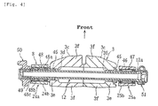
- is a cross-sectional view of a pivotal shaft on the rear arm (cross-sectional view along the line IV-IV in FIG. 3);
- FIG. 5
- is a top plan view of the rear arm;
- FIG. 6
- is a right side view of the rear arm;
- FIG. 7
- is a cross-sectional view along the line VII-VII in FIG. 3;
- FIG. 8
- is a cross-sectional view along the line VIII-VIII in FIG. 6;
- FIG. 9
- is a cross-sectional view along the line IX - IX in FIG. 8;
- FIG. 10
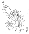
- is a left side view of a parts mounting bracket according to this embodiment;
- FIG. 11
- is a cross-sectional view along the line XI - XI in FIG. 10;
- FIG. 12
- is a cross-sectional view along the line XI - XI in FIG. 10;
- FIG. 13
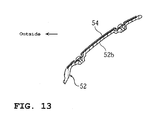
- is a cross-sectional view along the line XIII - XIII in FIG. 10;
- FIG. 14
- is a right side view of a parts mounting bracket according to the embodiment;
- FIG. 15
- is a cross-sectional view along the line XV - XV in FIG. 14; and
- FIG. 16
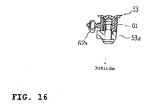
- is a cross-sectional view along the line XVI - XVI in FIG. 14.
- An embodiment is described with reference to the attached drawings, in which:
- FIGs. 1 through 16 illustrate a motorcycle according to an embodiment. FIGs. 1 and 2 are a side view and a top plan view of the motorcycle, respectively. FIG. 3 is a left side view of a rear arm. FIG. 4 is a cross-sectional view regarding a pivotal shaft of the rear arm (a cross-sectional view, taken along the line IV-IV in FIG. 3). FIG. 5 is a top plan view of the rear arm. FIG. 6 is a right side view of the rear arm. FIG. 7 is a cross-sectional view, taken along the line VII - VII in FIG. 3. FIG. 8 is a cross-sectional view, taken along the line VIII - VIII in FIG. 6. FIG. 9 is a cross-sectional view, taken along the line IX - IX in FIG. 8. FIG. 10 is a left side view of a left side footrest bracket. FIG. 11 is a cross-sectional view, taken along the line XI - XI in FIG. 10. FIG. 12 is a cross sectional view, taken along the line XII - XII in FIG. 10. FIG. 13 is a cross sectional view, taken along the line XIII - XIII in FIG. 10. FIG. 14 is a right side view of the right side footrest bracket. FIG. 15 is a cross-sectional view, taken along the line XV - XV in FIG. 14. FIG. 16 is a cross-sectional view, taken along the line XVI - XVI in FIG. 14.
- Additionally, the terms "right," "left," "front" and "rear" used in this embodiment refer to the right, left, front and rear sides for a rider seated on the seat.
- In the drawings,
reference numeral 1 defines a motorcycle which has the following structure: An engine 4 is installed in abody frame 3 extending from thehead pipe 2 to the rear of the motorcycle body. Afront fork 6 for supporting afront wheel 5 is pivotally supported by thehead pipe 2 so that it can be steered to both sides. Arear arm 8 for supporting arear wheel 7 is supported for vertical, pivotal motion by a reararm bracket portion 3b of thebody frame 3 via apivotal shaft 12. Further, a rearwheel suspension device 16 is disposed between therear arm 8 and the securing portion on the motorcycle body (engine). Afuel tank 9 and aseat 10 are disposed on thebody frame 3. Further, anexhaust device 22 extending to the rear of the motorcycle body is joined to the engine 4. - The
body frame 3 is of an assembling type constructed by a right and a left frame member as die-cast product, which are joined with fastening bolts. The respective right and the left frame member are structured by integrally molding a right and a leftmain frame portion arm bracket portion main frame portions arm bracket portions main frame portions - The front ends of the left and right
main frame portions arm bracket portion portion 3c. The surfaces of the left and the right rear arm pivotally-supportingposition 3c are finished with a sander or the like, which gives the surfaces a smooth flatness without irregularity. In addition, the rear ends of themain frame portion main frame portion arm bracket portions 3b. Thus, the engine 4 functions as a component for enhancing strength, constituting one part of thebody frame 3. - The
rear arm 8 includes a left and a rightrear arm body cross member 26 which connects therear arm bodies rear wheel 7. Therear wheel 7 is disposed between the rear ends of the left and the rightrear arm body rear arm bodies cross member 26 constitute a right and a leftarm head portion -
Cylindrical bearing portions arm head portions pivotal shaft 12. - On the bottom sides of the left and the right
rear arm body reinforcement sections - An area enclosed by the left and the right
arm head portion cross member 26, and thepivotal shaft 12 make an armhead portion space 8a (see FIG. 5). Within the armhead portion space 8a, a risingportion 19a of anexhaust pipe 19 connected to the engine 4 is disposed to go upward from the area below thepivotal shaft 12. Top end of the risingportion 19a is connected to a left and aright muffler seat 10, respectively. - As shown in FIG. 4, the left and the right
arm head portions portion body frame 3, respectively. The left and the right rear arm pivotally-supportingportions pivotal shaft 12 via the left and theright bearing portion -
Pivot holes portion Cylindrical stopper members pivot holes 3d, respectively, in the condition that the inward movement of eachstopper member portion 3c. - A
cylindrical collar member 46 is abutted on the external end face of theright stopper member 45 on thepivotal shaft 12. Thecollar member 46 is engaged with a stepped portion 12a on thepivotal shaft 12, and its outward movement in its axial direction is restricted. The bearingportion 25b on the rightarm head portion 25a is installed in the periphery of thecollar member 46 via aneedle bearing 47. - On the other hand, a
collar member 48a for aneedle bearing 48 mounted on thepivotal shaft 12, aball bearing 48b, and acollar member 48c are abutted one by one on the external end face of theleft stopper member 45 on thepivotal shaft 12. Then, by tightening anut 49, which has been screwed-on at the left end portion of thepivotal shaft 12, the left and the right rear arm pivotally-supportingportions 3c are joined with each other in the clamping condition via eachstopper member 45, thecollar members bearing 48b. -
Parts mounting brackets arm head portion parts mounting bracket brackets pivotal shaft 12 along the shaft axis. A right and leftfootrest assembly parts mounting brackets - As shown mainly in FIG. 3 as well as FIGs. 10 through 13, the
parts mounting bracket 50 on the left side has a structure that a bolt screw-inportion 50d having a tighteningslit 50c is integrally formed with aboss portion 50b which has a throughhole 50a for inserting thepivotal shaft 12, and that theboss portion 50b is integrally formed with afront edge portion 50e extending downward, arear edge portion 50f extending rearward, and alower edge portion 50g for connecting therear edge portion 50f and thefront edge portion 50e. - The
left footrest assembly 52 has a structure that afootrest bracket portion 52a of a generally crotched shape configured to cover the external surfaces of therear edge 50f and thelower edge 50g is formed integrally with aprotector portion 52b of a rhombic shape extending slantingly upward from thefootrest bracket portion 52a so as to face the rider's ankle, and that afootrest 55 and a shiftingpedal 56 are mounted at the rear end area of thefootrest bracket portion 52a. - The shifting
pedal 56 is joined to ashift rod 56a, which is in turn joined to a transmission in the unit case 4c. In addition, abank angle sensor 55a is formed so as to project at the distal end of the bottom face on thefootrest 55. Further, adesign plate 54 is attached on the external face of theprotector portion 52b to improve external appearance. - The
footrest bracket portion 52a of thefootrest assembly 52 is supported by theparts mounting bracket 50 interposing eachelastic member insert hole 50j is formed in each of therear edge portion 50f, thelower edge portion 50g, and a connecting portion 50h of bothedge portions elastic member 57 is put in everyinsert hole 50j, and abolt 58 is inserted into the axial core portion of theelastic member 57 from the inner side of the motorcycle body. Thefootrest assembly 52 is secured to theparts mounting bracket 50 by tightening thebolt 58 onto thefootrest bracket portion 52a. - In this way, each of the
elastic members 57 and thebolts 58 are masked by thefootrest bracket portion 52a of thefootrest assembly 52 so that they cannot be recognized from the outside of the motorcycle. - As shown mainly in FIG. 6 as well as FIGs. 14 through 16, the
parts mounting bracket 50 on the right side has a structure that a bolt screw-inportion 51 d having a tighteningslit 51 c is integrally formed with aboss portion 51 b which has a throughhole 51 a for inserting thepivotal shaft 12, and that a stretch-outportion 51e extending downward taking generally a sector shape is integrally formed with theboss portion 51 b. - The
right footrest assembly 53 has a structure that afootrest bracket portion 53a of a generally crotched shape configured to cover the external surface of a rearvertical edge 51f of the stretch-outportion 51e, is formed integrally with acylinder bracket portion 53c extending upward from thefootrest bracket portion 53a and with aprotector portion 53b of a rhombic shape extending slantingly upward from thefootrest bracket portion 53a so as to face the rider's ankle. It also has a structure that afootrest 60 and abrake pedal 61 are mounted at the rear end area of thefootrest bracket portion 53a.Reference numeral 54 defines a design plate, and 60a defines a bank angle sensor. - A
master cylinder 62 is mounted to thecylinder bracket portion 53c. Apiston rod 62a of themaster cylinder 62 is connected to thebrake pedal 61. Themaster cylinder 62 is also connected to areserve horse 63 and abrake hose 65. Thereserve hose 63 is connected to a reservoir tank (not shown), and thebrake hose 65 is connected to acaliper 64 for a disk brake of therear wheel 7.Reference numeral 66 defines a brake pedal return spring, and 67 a brake lamp switch. - The
footrest bracket portion 53a of thefootrest assembly 53 is supported by theparts mounting bracket 51 interposing eachelastic member Insert holes 51j are formed on a rearvertical edge 51f of theparts mounting bracket 51 so that they are apart each other by a given distance and the lines connecting their centers make a triangle. Theelastic member 68 is put in everyinsert hole 51j, and abolt 69 is inserted into the axial core portion of theelastic member 68 from the inner side of the motorcycle body. Thefootrest assembly 53 is secured to theparts mounting bracket 51 by tightening thebolt 69 into thefootrest bracket portion 53a. - In this way, each of the
elastic members 68 and thebolts 69 are masked by thefootrest bracket portion 53a of thefootrest assembly 53 so that they cannot be recognized from the outside of the motorcycle. - The
boss portion 50b of the leftparts mounting bracket 50 is secured to thepivotal shaft 12 by mounting the throughhole 50a onto the external circumference face of thenut 49 of thepivotal shaft 12, and fastening a tighteningbolt 70 inserted in the bolt screw-inportion 50d. - Further, as shown in FIG. 3 and FIG. 7, a
lower end portion 50e' of thefront edge portion 50e on theparts mounting bracket 50 is secured to the rear arm pivotally-supportingportion 3c of thebody frame 3 together with a stand bracket (intermediate bracket) 73 by means of twobolts parts mounting bracket 50, thestand bracket 73 is a forging of aluminum alloy. Thestand bracket 73 includes a tighteningportion 73a and anextended portion 73b extending downward from the tighteningportion 73a. A side stand 75 is mounted on theextended portion 73b for rotation between the operating position and the fold-up position. - The
boss portion 51 b of the rightparts mounting bracket 51 is secured to thepivotal shaft 12 by mounting the throughhole 51 a onto the external circumference face of thepivotal shaft 12, and fastening a tighteningbolt 71 inserted in the bolt screw-inportion 51 d. - Further, as shown in FIG. 6, FIG. 8, and FIG. 9, a
lower end portion 51e' of the stretch-outportion 51e on theparts mounting bracket 51 is secured to the rear arm pivotally-supportingportion 3c of thebody frame 3 together with an exhaust pipe supporting bracket (intermediate bracket) 77 by means of twobolts pipe supporting bracket 77 is independent from theparts mounting bracket 51 and is interposed between thelower end portion 51e' and the pivotally-supportingportion 3c. - The exhaust
pipe supporting bracket 77 is a die-cast product of aluminum alloy. The exhaustpipe supporting bracket 77 includes a tighteningportion 77a and acylindrical body 77b extending downward from the tighteningarea 77a. Theexhaust pipe 19 is supported by the exhaustpipe supporting bracket 77 via arubber dumper 79 mounted in thecylindrical body 77b. - According to this embodiment, the left and the right
parts mounting bracket arm head portion pivotal shaft 12. Thefoot rest assemblies parts mounting bracket elastic members elastic members right footrests - In addition, each
elastic member bolt footrest bracket portions footrest assemblies elastic members bolts - According to this embodiment, the left and the right rear arm pivotally-supporting
portion 3c do not have any recess or protrusion. This facilitates smoother surface finishing process when thebody frame 3 is a die-cast product. More specifically, when thebody frame 3 made by die casting process is employed for the purpose of weight reduction and improved external appearance, the casting surface tends to be rough because the die casting process gives adverse effect on the durability of the die. Thus, the body frame surface must be finished with a sander to make it flat and smooth. In the course of such smooth finishing, any recess or protrusion on the rear arm pivotally-supportingportion 3c will cause the problem, since they will impair the efficiency of the finishing process. - According to this embodiment, each
boss portion parts mounting bracket parts mounting brackets pivotal shaft 12 by tightening up theboss portions bolts parts mounting brackets footrests parts mounting bracket pivotal shaft 12 simply by loosening the tighteningbolts fastening bolts pivotal shaft 12, which facilitates the parts replacement work. More specifically, in the conventional structure disclosed in the publication of the prior art, the bracket is secured to the body frame by tightening it together with the rear arm by means of the pivotal shaft. In this case, the pivotal shaft must be removed from the body frame and the rear arm for maintenance or replacement, requiring a complex work. - According to this embodiment, the
boss portions parts mounting bracket pivotal shaft 12, while the left and the rightlower end portion 50e', 51e' are secured to the left and the right rear arm pivotally-supportingportion 3c, on thebody frame 3, interposing the independently providedstand bracket 73 and the exhaustpipe supporting bracket 77 respectively. Applying such structure, recesses and protrusions, such as a boss portion for securing eachparts mounting bracket portion 3c, are not required. This facilitates the surface smoothing treatment on the rear arm pivotally-supportingportion 3c. - In addition, each of the
parts mounting brackets portion 3c interposing the independently providedstand bracket 73 and the exhaustpipe supporting bracket 77 respectively. Therefore, the appropriate shape, material, manufacturing process, and other aspects may be chosen so as to satisfy the requirements for rigidity and strength regarding eachparts mounting bracket stand bracket 73 and the exhaustpipe supporting bracket 77. This enables weight reduction and cost cutting while maintaining the required rigidity and strength. - Further, the
pivotal shaft 12 is secured to the left and the right rear arm pivotally-supportingportion 3c of thebody frame 3, and theparts mounting bracket pivotal shaft 12. Further, thestand bracket 73 and the exhaust pipe supporting bracket 77are interposed between theparts mounting bracket portion 3c. - According to this embodiment, the
stand bracket 73 and theparts mounting bracket 50 are made as independent parts. This allows them to be made as a forging and a die casting of aluminum alloy, respectively, to assure the rigidity and the strength required for thestand bracket 73 for supporting the motorcycle body. This also allows the additional flexibility of shapes chosen, as well as the cost reduction. - According to this embodiment, both the exhaust
pipe supporting bracket 77 and theparts mounting bracket 51 are die castings of aluminum alloy. This allows these parts to be manufactured at lower cost than the forging process, while maintaining the rigidity and the strength required for supporting theexhaust pipe 19. - Also, the exhaust
pipe supporting bracket 77 and theparts mounting bracket 51 are made as independent parts. Therefore, either theparts mounting bracket 51 or the exhaustpipe supporting bracket 77 may be a forging, and the other be a casting. This allows higher flexibility regarding the manufacturing process, enabling the selection of manufacturing process that is effective for the cost reduction. - The description above discloses (amongst others) an embodiment of a motorcycle having a body frame; and a rear arm that is supported for vertical, pivotal motion by a rear arm pivotally-supporting portion on the body frame via a pivotal shaft, wherein the rear arm has a left and a right arm head portions with a pivotal shaft being inserted through the bearing portions located at their front ends; the left and the right arm head portions are disposed on the transversely outside of the rear arm pivotally-supporting portion; a parts mounting bracket is disposed on the outside of each of the left and the right arm head portions, a portion of each parts mounting bracket is secured to the pivotal shaft, and another portion thereof is secured to the body.
- Accordingly, a portion of the parts mounting bracket is secured to the pivotal shaft and another portion of the parts mounting bracket is secured to the body frame. Applying such structure, recesses and protrusions, such as a boss portion for securing the parts mounting bracket onto the body frame, are not required. This facilitates the surface finishing process on the body frame. Thus the smooth surface finishing process can be performed easily when the body frame is made of die casting, for instance. Also, improved rigidity can be obtained around the rear arm pivotally-supporting portion, as a portion of the parts mounting bracket is secured to the pivotal shaft, and another portion of the parts mounting bracket is secured to the body frame.
- According to another embodiment of the motorcycle, the another portion of the parts mounting bracket is secured to the body frame via an intermediate bracket provided as an independent part from the parts mounting bracket.
- Accordingly, the parts mounting bracket is secured to the body frame via the intermediate bracket provided as an independent part. More specifically, since the parts mounting bracket and the intermediate bracket are made as independent parts, appropriate shape, material, manufacturing process may be chosen so as to satisfy the requirements of rigidity and strength for each part, which enables reductions in regard to the cost and the weight.
- According to yet another embodiment, a boss portion to be mounted to the pivotal shaft is formed in the portion of the parts mounting bracket.
- Accordingly, the boss portion to be mounted to the pivotal shaft is formed on the parts mounting bracket, facilitating the correct positioning and mounting/removing process for the parts mounting bracket. If the parts mounting bracket is secured by being sandwiched and clamped by the pivotal shaft, for instance, mounting/removing of the parts mounting bracket will require the process of pulling-out the pivotal shaft, etc. The present invention eliminates such requirement.
- Further, preferably the intermediate bracket disposed on one side of the motorcycle body is formed as a stand bracket for supporting a side stand, the stand bracket and the parts mounting bracket being a forging and a die casting of light alloy, respectively.
- Accordingly, the intermediate bracket is formed as a stand bracket, and the stand bracket and the parts mounting bracket are made of light alloy forging and die casting, respectively. Since the stand bracket for supporting the motorcycle body is a casting as described above, the rigidity and the strength required for the stand bracket can be attained easily. Also, since the stand bracket and the parts mounting bracket are made as independent parts, excessive drawing depth at forging can be prevented. Thus the stand bracket can be made as a die forged product.
- According to still another embodiment, the intermediate bracket disposed on the other side of the motorcycle body is formed as an exhaust pipe supporting bracket, the exhaust pipe supporting bracket and the parts mounting bracket being die castings of light.
- Accordingly, the intermediate bracket is formed as an exhaust pipe supporting bracket, and both the exhaust pipe supporting bracket and the parts supporting bracket are made as a die cast product of light alloy. This allows these components to be fabricated at lower cost than the forging, and yet assures the rigidity and strength required for supporting the exhaust pipe. In addition, the exhaust pipe supporting bracket is made independently from the parts mounting bracket. Therefore, either the parts mounting bracket or the exhaust pipe supporting bracket may be made as a casting, and the other may be made as a die casting. This allows higher flexibility for choosing the manufacturing process which will allow cost and weight reductions.
- The description further discloses an embodiment a motorcycle comprising: a
body frame 3 of an assembling type with left and right frame members fastened with a bolt; arear arm 8 for supporting at its rear end a rear wheel and is supported for pivotal motion via apivotal shaft 12 by rear arm pivotally-supportingportions body frame 3; and brackets (support members) 50, 51 detachably mounted to thebody frame 3, wherein the rear arm pivotally-supportingportions body frame 3 have left andright side walls pivotal shaft 12 is inserted, and left and right connectingwalls respective side walls brackets first boss portions pivotal shaft 12 is inserted, andsecond boss portions 50e' and 51f fixed to thebody frame 3; and therear arm 8 has left and rightarm head portions pivotal shaft 12 is inserted and which are disposed between theside walls first boss portions - Preferably, the
side walls walls portions - Further, preferably the
arm head portions rear arm 8, and theside walls walls portions pivotal shaft 12. - Still further, preferably the brackets include a parts mounting bracket for mounting any one of a footrest, a side stand, or an exhaust device part to the body frame.
- Yet further, preferably the brackets include any two of a footrest bracket, a side stand bracket, or an exhaust device part supporting bracket.
- Also, it is beneficial if the connecting
walls portions pivotal shaft 12 in the motorcycle body. - Thus, according to a preferred embodiment, in order to provide a motorcycle that allows easy surface treatment on a body frame, and at the same time allows a parts mounting bracket to be firmly secured to the body frame,
parts mounting brackets arm head portions rear arm 8.Boss portions parts mounting bracket pivotal shaft 12, and another portion of eachparts mounting bracket body frame 3 via astand bracket 73 and an exhaustpipe supporting bracket 77, which are separated from theparts mounting brackets
Claims (12)
- Motorcycle comprising a body frame (3) and a rear arm (8) supported by a rear arm pivotally-supporting portion (3c) on the body frame (3) via a pivotal shaft (12), wherein a parts mounting bracket (50,51) is provided such that a first portion of the parts mounting bracket (50,51) is secured to the pivotal shaft (12) and a second portion thereof is secured to the body frame (3).
- Motorcycle according to claim 1, characterized in that the rear arm (8) is supported for vertical, pivotal motion by the rear arm pivotally-supporting portion (3c) on the body frame (3) via the pivotal shaft (12), wherein the rear arm (8) has a left and a right arm head portions (24a,25a) with the pivotal shaft (12) being inserted through bearing portions (24b,25b) located at their front ends, wherein the left and the right arm head portions (24a,25a) are disposed on the transversely outside of the rear arm pivotally-supporting portion (3c), wherein the parts mounting bracket (50,51) is disposed on the outside of each of the left and the right arm head portions (24a,25a), and wherein the first portion of each parts mounting bracket (50,51) is secured to the pivotal shaft (12) and the second portion thereof is secured to the body frame (3).
- Motorcycle according to claim 1 or 2, characterized in that the second portion of the parts mounting bracket (50,51) is secured to the body frame (3) via an intermediate bracket provided as an independent part from the parts mounting bracket (50,51).
- Motorcycle according to one of the claims 1 to 3, characterized by a boss portion formed in the portion of the parts mounting bracket (50,51) to be mounted to the pivotal shaft (12).
- Motorcycle according to claim 3 or 4, characterized in that the intermediate bracket disposed on a first side of the motorcycle body is formed as a stand bracket (73) for supporting a side stand, the stand bracket (73) and the parts mounting bracket (50,51) being a forging and a die-casting of light alloy, respectively.
- Motorcycle according to one of the claims 3 to 5, characterized in that the intermediate bracket disposed on a second side of the motorcycle body is formed as an exhaust pipe supporting bracket (77), the exhaust pipe supporting bracket (77) and the parts mounting bracket (50,51) being die castings of light alloy.
- Motorcycle according to one of the claims 1 to 6, characterized in that the body frame (3) is of an assembling type with left and right frame members (3a) fastened with a bolt, in that the rear arm (8) for supporting at its rear end a rear wheel (7) is supported for pivotal motion via the pivotal shaft (12) by the rear arm pivotally-supporting portions (3c) of the body frame (3), and in that brackets, as support members (50,51), are detachably mounted to the body frame (3), wherein the rear arm pivotally-supporting portions (3c) of the body frame (3) have left and right side walls (3e) through which the pivotal shaft (12) is inserted, and left and right connecting walls (3f) which extend from the respective side walls (3e) toward a center of a motorcycle body and abut on each other, wherein the brackets (50,51) have first boss portions (50d,51b) through which the pivotal shaft (12) is inserted, and second boss portions (50e',51f) fixed to the body frame (3), and wherein the rear arm (8) has left and right arm head portions (24b,25b) through which the pivotal shaft (12) is inserted and which are disposed between the side walls (3e) and the first boss portions (50d,51 b).
- Motorcycle according to claim 7, characterized in that the side walls (3e) and the connecting walls (3f) of the rear arm pivotally-supporting portions (3c) are formed integrally.
- Motorcycle according to claim 7 or 8, characterized in that the arm head portions (24b,25b) of the rear arm (8), and the side walls (3e) and the connecting walls (3f) of the rear arm pivotally-supporting portions (3c) are fastened together by means of the pivotal shaft (12).
- Motorcycle according to one of the claims 7 to 9, characterized in that the brackets include a parts mounting bracket for mounting any one of a footrest, a side stand, or an exhaust device part to the body frame.
- Motorcycle according to one of the claims 7 to 10, characterized in that the brackets include any two of a footrest bracket, a side stand bracket, or an exhaust device part supporting bracket.
- Motorcycle according to one of the claims 7 to 11, characterized in that the connecting walls (3f) of the rear arm pivotally-supporting portions (3c) are formed on front and rear sides of the pivotal shaft (12) in the motorcycle body.
Applications Claiming Priority (1)
| Application Number | Priority Date | Filing Date | Title |
|---|---|---|---|
| JP2004200996A JP2006021625A (en) | 2004-07-07 | 2004-07-07 | Motorcycle |
Publications (2)
| Publication Number | Publication Date |
|---|---|
| EP1614614A1 true EP1614614A1 (en) | 2006-01-11 |
| EP1614614B1 EP1614614B1 (en) | 2008-04-02 |
Family
ID=34981542
Family Applications (1)
| Application Number | Title | Priority Date | Filing Date |
|---|---|---|---|
| EP05014806A Expired - Lifetime EP1614614B1 (en) | 2004-07-07 | 2005-07-07 | Motorcycle |
Country Status (6)
| Country | Link |
|---|---|
| EP (1) | EP1614614B1 (en) |
| JP (1) | JP2006021625A (en) |
| CN (1) | CN100395150C (en) |
| AT (1) | ATE391071T1 (en) |
| DE (1) | DE602005005742T2 (en) |
| ES (1) | ES2303976T3 (en) |
Cited By (1)
| Publication number | Priority date | Publication date | Assignee | Title |
|---|---|---|---|---|
| US10328401B2 (en) | 2015-11-04 | 2019-06-25 | Franz Kaldewei Gmbh & Co. Kg | Valve for a water-supply system |
Families Citing this family (4)
| Publication number | Priority date | Publication date | Assignee | Title |
|---|---|---|---|---|
| JP4855201B2 (en) * | 2006-10-06 | 2012-01-18 | ヤマハ発動機株式会社 | Motorcycle |
| JP4995060B2 (en) * | 2007-12-17 | 2012-08-08 | 本田技研工業株式会社 | Motorcycle exhaust system |
| JP2009161019A (en) * | 2007-12-28 | 2009-07-23 | Yamaha Motor Co Ltd | Saddle riding vehicle |
| JP6232941B2 (en) * | 2013-11-05 | 2017-11-22 | スズキ株式会社 | Electric motor support structure |
Citations (2)
| Publication number | Priority date | Publication date | Assignee | Title |
|---|---|---|---|---|
| EP0826584A2 (en) * | 1996-08-30 | 1998-03-04 | Honda Giken Kogyo Kabushiki Kaisha | Body frame structure of motorcycle |
| JPH1086873A (en) | 1996-09-12 | 1998-04-07 | Honda Motor Co Ltd | Body frame structure of motorcycle |
Family Cites Families (3)
| Publication number | Priority date | Publication date | Assignee | Title |
|---|---|---|---|---|
| JP4132431B2 (en) * | 1999-06-29 | 2008-08-13 | 本田技研工業株式会社 | Motorcycle frame structure |
| JP3990551B2 (en) * | 2001-06-12 | 2007-10-17 | 本田技研工業株式会社 | Motorcycle frame structure |
| CN2536479Y (en) * | 2002-07-17 | 2003-02-19 | 重庆镁业科技股份有限公司 | Light magnesium alloy motorcycles |
-
2004
- 2004-07-07 JP JP2004200996A patent/JP2006021625A/en not_active Withdrawn
-
2005
- 2005-07-07 DE DE602005005742T patent/DE602005005742T2/en not_active Expired - Lifetime
- 2005-07-07 AT AT05014806T patent/ATE391071T1/en not_active IP Right Cessation
- 2005-07-07 ES ES05014806T patent/ES2303976T3/en not_active Expired - Lifetime
- 2005-07-07 EP EP05014806A patent/EP1614614B1/en not_active Expired - Lifetime
- 2005-07-07 CN CNB2005100827585A patent/CN100395150C/en not_active Expired - Fee Related
Patent Citations (2)
| Publication number | Priority date | Publication date | Assignee | Title |
|---|---|---|---|---|
| EP0826584A2 (en) * | 1996-08-30 | 1998-03-04 | Honda Giken Kogyo Kabushiki Kaisha | Body frame structure of motorcycle |
| JPH1086873A (en) | 1996-09-12 | 1998-04-07 | Honda Motor Co Ltd | Body frame structure of motorcycle |
Cited By (1)
| Publication number | Priority date | Publication date | Assignee | Title |
|---|---|---|---|---|
| US10328401B2 (en) | 2015-11-04 | 2019-06-25 | Franz Kaldewei Gmbh & Co. Kg | Valve for a water-supply system |
Also Published As
| Publication number | Publication date |
|---|---|
| JP2006021625A (en) | 2006-01-26 |
| CN1718495A (en) | 2006-01-11 |
| CN100395150C (en) | 2008-06-18 |
| DE602005005742T2 (en) | 2009-05-07 |
| ATE391071T1 (en) | 2008-04-15 |
| EP1614614B1 (en) | 2008-04-02 |
| ES2303976T3 (en) | 2008-09-01 |
| DE602005005742D1 (en) | 2008-05-15 |
Similar Documents
| Publication | Publication Date | Title |
|---|---|---|
| JP4364362B2 (en) | Motorcycle frame structure | |
| US7694985B2 (en) | Reinforced motorcycle frame | |
| TWI396646B (en) | Motorcycle | |
| JP4202791B2 (en) | Body frame structure of rough terrain vehicle | |
| JP6708687B2 (en) | Motorcycle seat frame | |
| US11267525B2 (en) | Saddle riding vehicle | |
| JP6722214B2 (en) | Saddle-type vehicle stay | |
| US20080223648A1 (en) | Body Frame of Motorcycle, Assembling Method of Mounting Engine on Body Frame, and Motorcycle Having Body Frame | |
| EP1614614B1 (en) | Motorcycle | |
| JP2010023732A (en) | Arrangement structure of rear-brake apparatus and motorcycle | |
| JP4577806B2 (en) | Body structure of motorcycle | |
| US7503415B2 (en) | Engine support structure of motorcycle | |
| JP2006021626A (en) | Motorcycle | |
| JP2007055488A (en) | Vehicle flap | |
| US20050247505A1 (en) | Frame and bracket system for motorized vehicle | |
| JP6484422B2 (en) | vehicle | |
| CN108688754B (en) | A step-by-step vehicle | |
| JPH10297569A (en) | Rear structure of motorcycle body | |
| JP2007196972A (en) | Motorcycle | |
| JP2003170882A (en) | Motorcycle frame structure | |
| JPH0581477B2 (en) | ||
| JP3157691U (en) | Saddle riding vehicle | |
| JP2019098863A (en) | Front fender support structure of saddle-riding type vehicle | |
| JP4464588B2 (en) | Suspension system for motorcycles | |
| JP2024535774A (en) | vehicle |
Legal Events
| Date | Code | Title | Description |
|---|---|---|---|
| PUAI | Public reference made under article 153(3) epc to a published international application that has entered the european phase |
Free format text: ORIGINAL CODE: 0009012 |
|
| 17P | Request for examination filed |
Effective date: 20051104 |
|
| AK | Designated contracting states |
Kind code of ref document: A1 Designated state(s): AT BE BG CH CY CZ DE DK EE ES FI FR GB GR HU IE IS IT LI LT LU LV MC NL PL PT RO SE SI SK TR |
|
| AX | Request for extension of the european patent |
Extension state: AL BA HR MK YU |
|
| AKX | Designation fees paid |
Designated state(s): AT BE BG CH CY CZ DE DK EE ES FI FR GB GR HU IE IS IT LI LT LU LV MC NL PL PT RO SE SI SK TR |
|
| 17Q | First examination report despatched |
Effective date: 20060217 |
|
| GRAP | Despatch of communication of intention to grant a patent |
Free format text: ORIGINAL CODE: EPIDOSNIGR1 |
|
| GRAS | Grant fee paid |
Free format text: ORIGINAL CODE: EPIDOSNIGR3 |
|
| GRAA | (expected) grant |
Free format text: ORIGINAL CODE: 0009210 |
|
| AK | Designated contracting states |
Kind code of ref document: B1 Designated state(s): AT BE BG CH CY CZ DE DK EE ES FI FR GB GR HU IE IS IT LI LT LU LV MC NL PL PT RO SE SI SK TR |
|
| REG | Reference to a national code |
Ref country code: GB Ref legal event code: FG4D |
|
| REG | Reference to a national code |
Ref country code: CH Ref legal event code: EP Ref country code: IE Ref legal event code: FG4D |
|
| REF | Corresponds to: |
Ref document number: 602005005742 Country of ref document: DE Date of ref document: 20080515 Kind code of ref document: P |
|
| REG | Reference to a national code |
Ref country code: ES Ref legal event code: FG2A Ref document number: 2303976 Country of ref document: ES Kind code of ref document: T3 |
|
| PG25 | Lapsed in a contracting state [announced via postgrant information from national office to epo] |
Ref country code: SI Free format text: LAPSE BECAUSE OF FAILURE TO SUBMIT A TRANSLATION OF THE DESCRIPTION OR TO PAY THE FEE WITHIN THE PRESCRIBED TIME-LIMIT Effective date: 20080402 |
|
| NLV1 | Nl: lapsed or annulled due to failure to fulfill the requirements of art. 29p and 29m of the patents act | ||
| PG25 | Lapsed in a contracting state [announced via postgrant information from national office to epo] |
Ref country code: PT Free format text: LAPSE BECAUSE OF FAILURE TO SUBMIT A TRANSLATION OF THE DESCRIPTION OR TO PAY THE FEE WITHIN THE PRESCRIBED TIME-LIMIT Effective date: 20080903 Ref country code: NL Free format text: LAPSE BECAUSE OF FAILURE TO SUBMIT A TRANSLATION OF THE DESCRIPTION OR TO PAY THE FEE WITHIN THE PRESCRIBED TIME-LIMIT Effective date: 20080402 Ref country code: FI Free format text: LAPSE BECAUSE OF FAILURE TO SUBMIT A TRANSLATION OF THE DESCRIPTION OR TO PAY THE FEE WITHIN THE PRESCRIBED TIME-LIMIT Effective date: 20080402 Ref country code: BG Free format text: LAPSE BECAUSE OF FAILURE TO SUBMIT A TRANSLATION OF THE DESCRIPTION OR TO PAY THE FEE WITHIN THE PRESCRIBED TIME-LIMIT Effective date: 20080702 |
|
| PG25 | Lapsed in a contracting state [announced via postgrant information from national office to epo] |
Ref country code: PL Free format text: LAPSE BECAUSE OF FAILURE TO SUBMIT A TRANSLATION OF THE DESCRIPTION OR TO PAY THE FEE WITHIN THE PRESCRIBED TIME-LIMIT Effective date: 20080402 Ref country code: AT Free format text: LAPSE BECAUSE OF FAILURE TO SUBMIT A TRANSLATION OF THE DESCRIPTION OR TO PAY THE FEE WITHIN THE PRESCRIBED TIME-LIMIT Effective date: 20080402 Ref country code: LV Free format text: LAPSE BECAUSE OF FAILURE TO SUBMIT A TRANSLATION OF THE DESCRIPTION OR TO PAY THE FEE WITHIN THE PRESCRIBED TIME-LIMIT Effective date: 20080402 |
|
| PG25 | Lapsed in a contracting state [announced via postgrant information from national office to epo] |
Ref country code: IS Free format text: LAPSE BECAUSE OF FAILURE TO SUBMIT A TRANSLATION OF THE DESCRIPTION OR TO PAY THE FEE WITHIN THE PRESCRIBED TIME-LIMIT Effective date: 20080802 |
|
| ET | Fr: translation filed | ||
| PG25 | Lapsed in a contracting state [announced via postgrant information from national office to epo] |
Ref country code: SE Free format text: LAPSE BECAUSE OF FAILURE TO SUBMIT A TRANSLATION OF THE DESCRIPTION OR TO PAY THE FEE WITHIN THE PRESCRIBED TIME-LIMIT Effective date: 20080702 Ref country code: LT Free format text: LAPSE BECAUSE OF FAILURE TO SUBMIT A TRANSLATION OF THE DESCRIPTION OR TO PAY THE FEE WITHIN THE PRESCRIBED TIME-LIMIT Effective date: 20080402 Ref country code: DK Free format text: LAPSE BECAUSE OF FAILURE TO SUBMIT A TRANSLATION OF THE DESCRIPTION OR TO PAY THE FEE WITHIN THE PRESCRIBED TIME-LIMIT Effective date: 20080402 Ref country code: CZ Free format text: LAPSE BECAUSE OF FAILURE TO SUBMIT A TRANSLATION OF THE DESCRIPTION OR TO PAY THE FEE WITHIN THE PRESCRIBED TIME-LIMIT Effective date: 20080402 |
|
| PLBE | No opposition filed within time limit |
Free format text: ORIGINAL CODE: 0009261 |
|
| STAA | Information on the status of an ep patent application or granted ep patent |
Free format text: STATUS: NO OPPOSITION FILED WITHIN TIME LIMIT |
|
| PG25 | Lapsed in a contracting state [announced via postgrant information from national office to epo] |
Ref country code: BE Free format text: LAPSE BECAUSE OF FAILURE TO SUBMIT A TRANSLATION OF THE DESCRIPTION OR TO PAY THE FEE WITHIN THE PRESCRIBED TIME-LIMIT Effective date: 20080402 Ref country code: RO Free format text: LAPSE BECAUSE OF FAILURE TO SUBMIT A TRANSLATION OF THE DESCRIPTION OR TO PAY THE FEE WITHIN THE PRESCRIBED TIME-LIMIT Effective date: 20080402 Ref country code: SK Free format text: LAPSE BECAUSE OF FAILURE TO SUBMIT A TRANSLATION OF THE DESCRIPTION OR TO PAY THE FEE WITHIN THE PRESCRIBED TIME-LIMIT Effective date: 20080402 |
|
| 26N | No opposition filed |
Effective date: 20090106 |
|
| PG25 | Lapsed in a contracting state [announced via postgrant information from national office to epo] |
Ref country code: MC Free format text: LAPSE BECAUSE OF NON-PAYMENT OF DUE FEES Effective date: 20080731 |
|
| PG25 | Lapsed in a contracting state [announced via postgrant information from national office to epo] |
Ref country code: EE Free format text: LAPSE BECAUSE OF FAILURE TO SUBMIT A TRANSLATION OF THE DESCRIPTION OR TO PAY THE FEE WITHIN THE PRESCRIBED TIME-LIMIT Effective date: 20080402 |
|
| PG25 | Lapsed in a contracting state [announced via postgrant information from national office to epo] |
Ref country code: IE Free format text: LAPSE BECAUSE OF NON-PAYMENT OF DUE FEES Effective date: 20080707 |
|
| PG25 | Lapsed in a contracting state [announced via postgrant information from national office to epo] |
Ref country code: CY Free format text: LAPSE BECAUSE OF FAILURE TO SUBMIT A TRANSLATION OF THE DESCRIPTION OR TO PAY THE FEE WITHIN THE PRESCRIBED TIME-LIMIT Effective date: 20080402 |
|
| REG | Reference to a national code |
Ref country code: CH Ref legal event code: PL |
|
| PG25 | Lapsed in a contracting state [announced via postgrant information from national office to epo] |
Ref country code: LI Free format text: LAPSE BECAUSE OF NON-PAYMENT OF DUE FEES Effective date: 20090731 Ref country code: CH Free format text: LAPSE BECAUSE OF NON-PAYMENT OF DUE FEES Effective date: 20090731 |
|
| PG25 | Lapsed in a contracting state [announced via postgrant information from national office to epo] |
Ref country code: HU Free format text: LAPSE BECAUSE OF FAILURE TO SUBMIT A TRANSLATION OF THE DESCRIPTION OR TO PAY THE FEE WITHIN THE PRESCRIBED TIME-LIMIT Effective date: 20081003 Ref country code: LU Free format text: LAPSE BECAUSE OF NON-PAYMENT OF DUE FEES Effective date: 20080707 |
|
| PG25 | Lapsed in a contracting state [announced via postgrant information from national office to epo] |
Ref country code: TR Free format text: LAPSE BECAUSE OF FAILURE TO SUBMIT A TRANSLATION OF THE DESCRIPTION OR TO PAY THE FEE WITHIN THE PRESCRIBED TIME-LIMIT Effective date: 20080402 |
|
| PG25 | Lapsed in a contracting state [announced via postgrant information from national office to epo] |
Ref country code: GR Free format text: LAPSE BECAUSE OF FAILURE TO SUBMIT A TRANSLATION OF THE DESCRIPTION OR TO PAY THE FEE WITHIN THE PRESCRIBED TIME-LIMIT Effective date: 20080703 |
|
| REG | Reference to a national code |
Ref country code: FR Ref legal event code: PLFP Year of fee payment: 12 |
|
| REG | Reference to a national code |
Ref country code: FR Ref legal event code: PLFP Year of fee payment: 13 |
|
| REG | Reference to a national code |
Ref country code: FR Ref legal event code: PLFP Year of fee payment: 14 |
|
| PGFP | Annual fee paid to national office [announced via postgrant information from national office to epo] |
Ref country code: GB Payment date: 20200727 Year of fee payment: 16 Ref country code: FR Payment date: 20200721 Year of fee payment: 16 Ref country code: ES Payment date: 20200922 Year of fee payment: 16 |
|
| PGFP | Annual fee paid to national office [announced via postgrant information from national office to epo] |
Ref country code: IT Payment date: 20200724 Year of fee payment: 16 |
|
| GBPC | Gb: european patent ceased through non-payment of renewal fee |
Effective date: 20210707 |
|
| PG25 | Lapsed in a contracting state [announced via postgrant information from national office to epo] |
Ref country code: GB Free format text: LAPSE BECAUSE OF NON-PAYMENT OF DUE FEES Effective date: 20210707 |
|
| PG25 | Lapsed in a contracting state [announced via postgrant information from national office to epo] |
Ref country code: FR Free format text: LAPSE BECAUSE OF NON-PAYMENT OF DUE FEES Effective date: 20210731 |
|
| PG25 | Lapsed in a contracting state [announced via postgrant information from national office to epo] |
Ref country code: IT Free format text: LAPSE BECAUSE OF NON-PAYMENT OF DUE FEES Effective date: 20210707 |
|
| REG | Reference to a national code |
Ref country code: ES Ref legal event code: FD2A Effective date: 20220829 |
|
| PG25 | Lapsed in a contracting state [announced via postgrant information from national office to epo] |
Ref country code: ES Free format text: LAPSE BECAUSE OF NON-PAYMENT OF DUE FEES Effective date: 20210708 |
|
| PGFP | Annual fee paid to national office [announced via postgrant information from national office to epo] |
Ref country code: DE Payment date: 20220620 Year of fee payment: 18 |
|
| REG | Reference to a national code |
Ref country code: DE Ref legal event code: R119 Ref document number: 602005005742 Country of ref document: DE |
|
| PG25 | Lapsed in a contracting state [announced via postgrant information from national office to epo] |
Ref country code: DE Free format text: LAPSE BECAUSE OF NON-PAYMENT OF DUE FEES Effective date: 20240201 |