EP1613122A1 - Method for setting up connections between nodes with multiple network capabilities - Google Patents
Method for setting up connections between nodes with multiple network capabilities Download PDFInfo
- Publication number
- EP1613122A1 EP1613122A1 EP04291695A EP04291695A EP1613122A1 EP 1613122 A1 EP1613122 A1 EP 1613122A1 EP 04291695 A EP04291695 A EP 04291695A EP 04291695 A EP04291695 A EP 04291695A EP 1613122 A1 EP1613122 A1 EP 1613122A1
- Authority
- EP
- European Patent Office
- Prior art keywords
- node
- signalling
- signalling procedure
- procedure
- setting
- Prior art date
- Legal status (The legal status is an assumption and is not a legal conclusion. Google has not performed a legal analysis and makes no representation as to the accuracy of the status listed.)
- Granted
Links
- 238000000034 method Methods 0.000 title claims abstract description 210
- 230000011664 signaling Effects 0.000 claims abstract description 254
- 239000000835 fiber Substances 0.000 claims description 28
- 238000011144 upstream manufacturing Methods 0.000 claims description 6
- 230000006870 function Effects 0.000 claims description 5
- 230000014509 gene expression Effects 0.000 description 3
- 230000008878 coupling Effects 0.000 description 2
- 238000010168 coupling process Methods 0.000 description 2
- 238000005859 coupling reaction Methods 0.000 description 2
- 238000003780 insertion Methods 0.000 description 2
- 230000037431 insertion Effects 0.000 description 2
- 230000003287 optical effect Effects 0.000 description 2
- 239000013307 optical fiber Substances 0.000 description 2
- 230000015654 memory Effects 0.000 description 1
- 230000004044 response Effects 0.000 description 1
Images


Classifications
-
- H—ELECTRICITY
- H04—ELECTRIC COMMUNICATION TECHNIQUE
- H04Q—SELECTING
- H04Q3/00—Selecting arrangements
- H04Q3/0016—Arrangements providing connection between exchanges
- H04Q3/0025—Provisions for signalling
Definitions
- the invention relates to a network for setting up a connection from a first node to a second node through transmitting a request message from the first node to the second node and transmitting an allocation message from the second node to the first node.
- Examples of such networks are optical fibre networks, the nodes for example being optical switches.
- a prior art network is of common general knowledge.
- a first node transmits a request message to a second node and receives in return an allocation message from the second node. These messages are related to one and the same signalling procedure.
- the known network is disadvantageous, inter alia, due to its nodes sometimes being capable to handle different signalling procedures. In that case, for each one of the signalling procedures, a request message and an allocation message need to be exchanged. This is relatively inefficient (two separate round trips).
- the network according to the invention is characterised in that the request message comprises an indication for indicating the first node's capabilities with respect to a first signalling procedure and with respect to a second signalling procedure, the allocation message comprising an instruction for instructing the first node to use one of the signalling procedures for the setting up of the connection.
- An embodiment of the network according to the invention is characterised in that the first node comprises a first controller for supplying the indication comprising a first preference value for the first signalling procedure and a second preference value for the second signalling procedure, the second node comprising a second controller for supplying the instruction comprising signalling information and a signalling procedure assignment.
- the first (second) preference value for example comprises a bit having the value zero in case the first node cannot handle or does not want to handle the first (second) signalling procedure and having the value one in case the first node can handle or does want to handle the first (second) signalling procedure. In case both preference values have the value one, the second node will have an option of selecting one of the signalling procedures.
- An embodiment of the network according to the invention is characterised in that the second controller is arranged to run a label assignment algorithm for making the signalling procedure assignment in dependence of the preference values, the first controller being arranged to derive further signalling information from the signalling information, which signalling information is related to the first signalling procedure and which further signalling information is related to the second signalling procedure.
- the label assignment algorithm generates the signalling procedure assignment for assigning one of the signalling procedures to the first node.
- the signalling information can be related to the first signalling procedure, as long as the first node is capable of deriving the further signalling information from this signalling information. Then, the second node does not need to adapt this signalling information, but can send the signalling information to the first node independently from the kind of signalling procedure to be used.
- This network according to the invention is very efficient.
- An embodiment of the network according to the invention is characterised in that the first signalling procedure is wavelength switching, the second signalling procedure being waveband switching.
- the signalling information then comprises the wavelength to be used.
- this waveband can be derived from the wavelenght information.
- An embodiment of the network according to the invention is characterised in that the first signalling procedure is waveband switching, the second signalling procedure being fibre switching.
- the signalling information then comprises the waveband to be used.
- the fibre to be used can be derived from the waveband information.
- An embodiment of the network according to the invention is characterised in that the first node is an upstream node, the second node being a downstream node.
- connection is then set up in a downstream direction, with the downstream node instructing the upstream node which kind of signalling procedure is to be used.
- the invention also relates to a first node for use in a network for setting up a connection from the first node to a second node through transmitting a request message from the first node to the second node and transmitting an allocation message from the second node to the first node.
- the first node according to the invention is characterised in that the request message comprises an indication for indicating the first node's capabilities with respect to a first signalling procedure and with respect to a second signalling procedure, the allocation message comprising an instruction for instructing the first node to use one of the signalling procedures for the setting up of the connection.
- the invention yet also relates to a second node for use in a network for setting up a connection from a first node to the second node through transmitting a request message from the first node to the second node and transmitting an allocation message from the second node to the first node.
- the second node according to the invention is characterised in that the request message comprises an indication for indicating the first node's capabilities with respect to a first signalling procedure and with respect to a second signalling procedure, the allocation message comprising an instruction for instructing the first node to use one of the signalling procedures for the setting up of the connection.
- the invention further relates to a method for setting up a connection from a first node to a second node, which method comprises the steps of transmitting a request message from the first node to the second node and of transmitting an allocation message from the second node to the first node.
- the method according to the invention is characterised in that the request message comprises an indication for indicating the first node's capabilities with respect to a first signalling procedure and with respect to a second signalling procedure, the allocation message comprising an instruction for instructing the first node to use one of the signalling procedures for the setting up of the connection.
- the invention yet further relates to a processor program product for setting up a connection from a first node to a second node, which processor program product comprises the functions of transmitting a request message from the first node to the second node and of transmitting an allocation message from the second node to the first node.
- the processor program product according to the invention is characterised in that the request message comprises an indication for indicating the first node's capabilities with respect to a first signalling procedure and with respect to a second signalling procedure, the allocation message comprising an instruction for instructing the first node to use one of the signalling procedures for the setting up of the connection.
- Embodiments of the first node according to the invention and of the second node according to the invention and of the method according to the invention and of the processor program product according to the invention correspond with the embodiments of the network according to the invention.
- the invention is based upon an insight, inter alia, that two separate round trips for two separate signalling procedures make the network relatively inefficient, and is based upon a basic idea, inter alia, that the first node's capabilities with respect to a first signalling procedure and with respect to a second signalling procedure can be inserted into one and the same request message. In return, one allocation message is sufficient to instruct the first node to use one of the signalling procedures for the setting up of the connection.
- the invention solves the problem, inter alia, to provide a network as defined in the preamble, which is relatively efficient, and is advantageous, inter alia, in that only one round trip is needed.
- a first node 1 comprises a first interface 12 such as for example a first transceiver coupled to a fibre 9, and comprises a second interface 13 such as for example a second transceiver coupled to a fibre 5. Both interfaces 12,13 are coupled to each other via a parallel circuit of a wavelength switch 14, a waveband switch 15 and a fibre switch 16. All units 12-16 are coupled to a first controller 11.
- a second node 2 comprises a first interface 22 such as for example a first transceiver coupled to the fibre 5, and comprises a second interface 23 such as for example a second transceiver coupled to a fibre 6. Both interfaces 22,23 are coupled to each other via a parallel circuit of a wavelength switch 24, a waveband switch 25 and a fibre switch 26. All units 22-26 are coupled to a second controller 21.
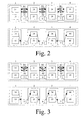
- the first example for setting up a connection between nodes 1-4 according to the invention as shown in Fig. 2 discloses in its upper part and in its lower part four nodes 1-4.
- the node 1 comprises the wavelength switch 14 and the waveband switch 15, the node 2 comprises the wavelength switch 24 and the waveband switch 25, the node 3 comprises a wavelength switch 34 and a waveband switch 35, and the node 4 comprises a wavelength switch 44 and a waveband switch 45.
- the fibre 5 is present, between the nodes 2 and 3, the fibre 6 is present, and between the nodes 3 and 4, a fibre 7 is present.
- Fig. 2 further discloses in its upper part some request and allocation messages.
- the node 1 sends a request message R1 to the node 2, which sends a request message R2 to the node 3, which sends a request message R3 to the node 4.
- the node 4 sends in return an allocation message A3 to the node 3, which sends an allocation message A2 to the node 2, which sends an allocation message A1 to the node 1.
- Fig. 2 further discloses in its lower part the connection as it is set up in response to the allocation messages A1-A3.
- the node 1 has sent the request message R1 comprising an indication for indicating this node's capabilities with respect to a first signalling procedure (wavelength switching via the wavelength switch 14) and with respect to a second signalling procedure (waveband switching via the waveband switch 15).
- the node 2 has sent the request message R2 comprising an indication for indicating this node's capabilities with respect to a first signalling procedure (wavelength switching via the wavelength switch 24) and with respect to a second signalling procedure (waveband switching via the waveband switch 25).
- the node 3 has sent the request message R3 comprising an indication for indicating this node's capabilities with respect to a first signalling procedure (wavelength switching via the wavelength switch 34) and with respect to a second signalling procedure (waveband switching via the waveband switch 35).
- the node 4 has sent back the allocation message A3 comprising an instruction for instructing the node 3 to use one of the signalling procedures for the setting up of the connection.
- the node 3 has sent back the allocation message A2 comprising an instruction for instructing the node 2 to use one of the signalling procedures for the setting up of the connection.
- the node 2 has sent back the allocation message A1 comprising an instruction for instructing the node 1 to use one of the signalling procedures for the setting up of the connection.
- the second example for setting up a connection between nodes 1-4 according to the invention as shown in Fig. 3 discloses in its upper part and in its lower part four nodes 1-4 as already described above.
- the node 1 has sent the request message R1 comprising an indication for indicating this node's capabilities with respect to a first signalling procedure (wavelength switching via the wavelength switch 14) and with respect to a second signalling procedure (waveband switching via the waveband switch 15).
- the node 2 has sent the request message R2 comprising an indication for indicating this node's capabilities with respect to a first signalling procedure (wavelength switching via the wavelength switch 24) and with respect to a second signalling procedure (waveband switching via the waveband switch 25).
- the node 3 has sent the request message R3 comprising an indication for indicating this node's capabilities with respect to a first signalling procedure (wavelength switching via the wavelength switch 34) and with respect to a second signalling procedure (waveband switching via the waveband switch 35).
- the node 4 has sent back the allocation message A3 comprising an instruction for instructing the node 3 to use one of the signalling procedures for the setting up of the connection.
- the node 3 has sent back the allocation message A2 comprising an instruction for instructing the node 2 to use one of the signalling procedures for the setting up of the connection.
- the node 2 has sent back the allocation message A1 comprising an instruction for instructing the node 1 to use one of the signalling procedures for the setting up of the connection.
- the third example for setting up a connection between nodes 1-4 according to the invention as shown in Fig. 4 discloses in its upper part and in its lower part four nodes 1-4 as already described above, apart from the fact that the node 1 does not comprise the waveband switch 15. Alternatively, this waveband switch 14 is out of order.
- the node 1 has sent the request message R1 comprising an indication for indicating this node's capabilities with respect to a first signalling procedure (wavelength switching via the wavelength switch 14) and with respect to a second signalling procedure (waveband switching via the waveband switch 15).
- the node 2 has sent the request message R2 comprising an indication for indicating this node's capabilities with respect to a first signalling procedure (wavelength switching via the wavelength switch 24) and with respect to a second signalling procedure (waveband switching via the waveband switch 25).
- the node 3 has sent the request message R3 comprising an indication for indicating this node's capabilities with respect to a first signalling procedure (wavelength switching via the wavelength switch 34) and with respect to a second signalling procedure (waveband switching via the waveband switch 35).
- the node 4 has sent back the allocation message A3 comprising an instruction for instructing the node 3 to use one of the signalling procedures for the setting up of the connection.
- the node 3 has sent back the allocation message A2 comprising an instruction for instructing the node 2 to use one of the signalling procedures for the setting up of the connection.
- the node 2 has sent back the allocation message A1 comprising an instruction for instructing the node 1 to use one of the signalling procedures for the setting up of the connection.
- the fourth example for setting up a connection between nodes 1-4 according to the invention as shown in Fig. 4 discloses in its upper part and in its lower part four nodes 1-4 as already described above.
- the node 1 has sent the request message R1 comprising an indication for indicating this node's capabilities with respect to a first signalling procedure (wavelength switching via the wavelength switch 14) and with respect to a second signalling procedure (waveband switching via the waveband switch 15).
- the node 2 has sent the request message R2 comprising an indication for indicating this node's capabilities with respect to a first signalling procedure (wavelength switching via the wavelength switch 24) and with respect to a second signalling procedure (waveband switching via the waveband switch 25).
- the node 3 has sent the request message R3 comprising an indication for indicating this node's capabilities with respect to a first signalling procedure (wavelength switching via the wavelength switch 34) and with respect to a second signalling procedure (waveband switching via the waveband switch 35).
- the node 4 has sent back the allocation message A3 comprising an instruction for instructing the node 3 to use one of the signalling procedures for the setting up of the connection.
- the node 3 has sent back the allocation message A2 comprising an instruction for instructing the node 2 to use one of the signalling procedures for the setting up of the connection.
- the node 2 has sent back the allocation message A1 comprising an instruction for instructing the node 1 to use one of the signalling procedures for the setting up of the connection.
- the request messages R1-R3 need to get an additional field or a label.
- the insertion of the indication can be done via one of the interfaces 12,13,22,23 or via one of the switches 14,15,16,24,25,26.
- the controllers 11,21 supply the indication comprising a first preference value for the first signalling procedure and a second preference value for the second signalling procedure and possibly a third preference value for the third signalling procedure etc.
- the instruction for instructing the node to use one of the signalling procedures for the setting up of the connection either an existing field or label is used, or the allocation messages A1-A3 need to get an additional field or label.
- the insertion of the instruction can be done via one of the interfaces 12,13,22,23 or via one of the switches 14,15,16,24,25,26.
- the controllers 11,21 supply the instruction comprising signalling information and a signalling procedure assignment.
- the controllers 11,21 are arranged to run a label assignment algorithm for making the signalling procedure assignment in dependence of the preference values and are arranged to derive further signalling information from the signalling information, which signalling information is related to the first signalling procedure and which further signalling information is related to the second signalling procedure, and are possibly arranged to derive yet further signalling information from the (further) signalling information, which (further) signalling information is related to the first (second) signalling procedure and which yet further signalling information is related to the third signalling procedure etc.
- the label assignment algorithm generates the signalling procedure assignment for assigning one of the signalling procedures to the node receiving the allocation message.
- the signalling information can be related to the first signalling procedure, as long as this node is capable of deriving the (yet) further signalling information from this (further) signalling information. Then, the node sending the allocation message does not need to adapt this signalling information, but can send the signalling information to the node receiving the allocation message independently from the kind of signalling procedure to be used. To be able to derive the (yet) further signalling information from the (further) signalling information, for example table memories are used.
- the first signalling procedure is for example wavelength switching
- the second signalling procedure is for example waveband switching.
- the signalling information then comprises the wavelength to be used. In case of the waveband needing to be switched (possibly preferably), this waveband can be derived from the wavelenght information.
- the first signalling procedure is for example waveband switching
- the second signalling procedure is for example fibre switching.
- the signalling information then comprises the waveband to be used. In case of the fibre needing to be switched (possibly preferably), the fibre to be used can be derived from the waveband information. Other kinds of switching procedures are not to be excluded.
- the node 1 is for example located at an upstream location, and the node 4 is for example located at a downstream location.
- the connection is then set up in a downstream direction, with the downstream node instructing the upstream node which kind of signalling procedure is to be used.
- the request messages go downstream, the allocation messages go upstream.
Landscapes
- Engineering & Computer Science (AREA)
- Computer Networks & Wireless Communication (AREA)
- Optical Communication System (AREA)
- Data Exchanges In Wide-Area Networks (AREA)
- Communication Control (AREA)
Abstract
Description
- The invention relates to a network for setting up a connection from a first node to a second node through transmitting a request message from the first node to the second node and transmitting an allocation message from the second node to the first node.
- Examples of such networks are optical fibre networks, the nodes for example being optical switches.
- A prior art network is of common general knowledge. A first node transmits a request message to a second node and receives in return an allocation message from the second node. These messages are related to one and the same signalling procedure.
- The known network is disadvantageous, inter alia, due to its nodes sometimes being capable to handle different signalling procedures. In that case, for each one of the signalling procedures, a request message and an allocation message need to be exchanged. This is relatively inefficient (two separate round trips).
- It is an object of the invention, inter alia, to provide a network as defined above, which is relatively efficient.
- The network according to the invention is characterised in that the request message comprises an indication for indicating the first node's capabilities with respect to a first signalling procedure and with respect to a second signalling procedure, the allocation message comprising an instruction for instructing the first node to use one of the signalling procedures for the setting up of the connection.
- By providing the request message with the indication and by providing the allocation message with the instruction, only one round trip is needed. This network according to the invention is therefore more efficient.
- An embodiment of the network according to the invention is characterised in that the first node comprises a first controller for supplying the indication comprising a first preference value for the first signalling procedure and a second preference value for the second signalling procedure, the second node comprising a second controller for supplying the instruction comprising signalling information and a signalling procedure assignment.
- The first (second) preference value for example comprises a bit having the value zero in case the first node cannot handle or does not want to handle the first (second) signalling procedure and having the value one in case the first node can handle or does want to handle the first (second) signalling procedure. In case both preference values have the value one, the second node will have an option of selecting one of the signalling procedures.
- An embodiment of the network according to the invention is characterised in that the second controller is arranged to run a label assignment algorithm for making the signalling procedure assignment in dependence of the preference values, the first controller being arranged to derive further signalling information from the signalling information, which signalling information is related to the first signalling procedure and which further signalling information is related to the second signalling procedure.
- The label assignment algorithm generates the signalling procedure assignment for assigning one of the signalling procedures to the first node. The signalling information can be related to the first signalling procedure, as long as the first node is capable of deriving the further signalling information from this signalling information. Then, the second node does not need to adapt this signalling information, but can send the signalling information to the first node independently from the kind of signalling procedure to be used. This network according to the invention is very efficient.
- An embodiment of the network according to the invention is characterised in that the first signalling procedure is wavelength switching, the second signalling procedure being waveband switching.
- The signalling information then comprises the wavelength to be used. In case of the waveband needing to be switched (possibly preferably), this waveband can be derived from the wavelenght information.
- An embodiment of the network according to the invention is characterised in that the first signalling procedure is waveband switching, the second signalling procedure being fibre switching.
- The signalling information then comprises the waveband to be used. In case of the fibre needing to be switched (possibly preferably), the fibre to be used can be derived from the waveband information.
- An embodiment of the network according to the invention is characterised in that the first node is an upstream node, the second node being a downstream node.
- The connection is then set up in a downstream direction, with the downstream node instructing the upstream node which kind of signalling procedure is to be used.
- The invention also relates to a first node for use in a network for setting up a connection from the first node to a second node through transmitting a request message from the first node to the second node and transmitting an allocation message from the second node to the first node.
- The first node according to the invention is characterised in that the request message comprises an indication for indicating the first node's capabilities with respect to a first signalling procedure and with respect to a second signalling procedure, the allocation message comprising an instruction for instructing the first node to use one of the signalling procedures for the setting up of the connection.
- The invention yet also relates to a second node for use in a network for setting up a connection from a first node to the second node through transmitting a request message from the first node to the second node and transmitting an allocation message from the second node to the first node.
- The second node according to the invention is characterised in that the request message comprises an indication for indicating the first node's capabilities with respect to a first signalling procedure and with respect to a second signalling procedure, the allocation message comprising an instruction for instructing the first node to use one of the signalling procedures for the setting up of the connection.
- The invention further relates to a method for setting up a connection from a first node to a second node, which method comprises the steps of transmitting a request message from the first node to the second node and of transmitting an allocation message from the second node to the first node.
- The method according to the invention is characterised in that the request message comprises an indication for indicating the first node's capabilities with respect to a first signalling procedure and with respect to a second signalling procedure, the allocation message comprising an instruction for instructing the first node to use one of the signalling procedures for the setting up of the connection.
- The invention yet further relates to a processor program product for setting up a connection from a first node to a second node, which processor program product comprises the functions of transmitting a request message from the first node to the second node and of transmitting an allocation message from the second node to the first node.
- The processor program product according to the invention is characterised in that the request message comprises an indication for indicating the first node's capabilities with respect to a first signalling procedure and with respect to a second signalling procedure, the allocation message comprising an instruction for instructing the first node to use one of the signalling procedures for the setting up of the connection.
- Embodiments of the first node according to the invention and of the second node according to the invention and of the method according to the invention and of the processor program product according to the invention correspond with the embodiments of the network according to the invention.
- The invention is based upon an insight, inter alia, that two separate round trips for two separate signalling procedures make the network relatively inefficient, and is based upon a basic idea, inter alia, that the first node's capabilities with respect to a first signalling procedure and with respect to a second signalling procedure can be inserted into one and the same request message. In return, one allocation message is sufficient to instruct the first node to use one of the signalling procedures for the setting up of the connection.
- The invention solves the problem, inter alia, to provide a network as defined in the preamble, which is relatively efficient, and is advantageous, inter alia, in that only one round trip is needed.
- These and other aspects of the invention will be apparent from and elucidated with reference to the embodiments(s) described hereinafter.
- Fig. 1 shows diagrammatically a network according to the invention comprising nodes according to the invention;
- Fig. 2 shows diagrammatically a first example for setting up a connection between nodes according to the invention;
- Fig. 3 shows diagrammatically a second example for setting up a connection between nodes according to the invention;
- Fig. 4 shows diagrammatically a third example for setting up a connection between nodes according to the invention; and
- Fig. 5 shows diagrammatically a fourth example for setting up a connection between nodes according to the invention.
- The
network 8 according to the invention as shown in Fig. 1 such as for example an optical fibre network comprisesnodes first node 1 comprises afirst interface 12 such as for example a first transceiver coupled to afibre 9, and comprises asecond interface 13 such as for example a second transceiver coupled to afibre 5. Bothinterfaces wavelength switch 14, awaveband switch 15 and afibre switch 16. All units 12-16 are coupled to afirst controller 11. Asecond node 2 comprises afirst interface 22 such as for example a first transceiver coupled to thefibre 5, and comprises asecond interface 23 such as for example a second transceiver coupled to afibre 6. Bothinterfaces wavelength switch 24, awaveband switch 25 and afibre switch 26. All units 22-26 are coupled to asecond controller 21. - The performance of the
network 8 and itsnodes - The first example for setting up a connection between nodes 1-4 according to the invention as shown in Fig. 2 discloses in its upper part and in its lower part four nodes 1-4. The
node 1 comprises thewavelength switch 14 and thewaveband switch 15, thenode 2 comprises thewavelength switch 24 and thewaveband switch 25, thenode 3 comprises awavelength switch 34 and awaveband switch 35, and thenode 4 comprises awavelength switch 44 and awaveband switch 45. Between thenodes fibre 5 is present, between thenodes fibre 6 is present, and between thenodes fibre 7 is present. Fig. 2 further discloses in its upper part some request and allocation messages. Thenode 1 sends a request message R1 to thenode 2, which sends a request message R2 to thenode 3, which sends a request message R3 to thenode 4. Thenode 4 sends in return an allocation message A3 to thenode 3, which sends an allocation message A2 to thenode 2, which sends an allocation message A1 to thenode 1. Fig. 2 further discloses in its lower part the connection as it is set up in response to the allocation messages A1-A3. - The
node 1 has sent the request message R1 comprising an indication for indicating this node's capabilities with respect to a first signalling procedure (wavelength switching via the wavelength switch 14) and with respect to a second signalling procedure (waveband switching via the waveband switch 15). This indication comprises a first preference value P= 1 indicated by the first non-empty block of R1 for the first signalling procedure and a second preference value Q=1 indicated by the second non-empty block of R1 for the second signalling procedure. So, thenode 1 has indicated that both signalling procedures are possible. - The
node 2 has sent the request message R2 comprising an indication for indicating this node's capabilities with respect to a first signalling procedure (wavelength switching via the wavelength switch 24) and with respect to a second signalling procedure (waveband switching via the waveband switch 25). This indication comprises a first preference value P=1 indicated by the first non-empty block of R2 for the first signalling procedure and a second preference value Q=1 indicated by the second non-empty block of R1 for the second signalling procedure. So, thenode 2 has indicated that both signalling procedures are possible. - The
node 3 has sent the request message R3 comprising an indication for indicating this node's capabilities with respect to a first signalling procedure (wavelength switching via the wavelength switch 34) and with respect to a second signalling procedure (waveband switching via the waveband switch 35). This indication comprises a first preference value P=1 indicated by the first non-empty block of R3 for the first signalling procedure and a second preference value Q=0 indicated by the second empty block of R3 for the second signalling procedure. So, thenode 3 has indicated that the first signalling procedure is to be preferred. - The
node 4 has sent back the allocation message A3 comprising an instruction for instructing thenode 3 to use one of the signalling procedures for the setting up of the connection. This instruction comprises signalling information and a signalling procedure assignment. Because P=1 and Q=0, thenode 4 has not had any option of selecting a signalling procedure, and as indicated by the non-empty block of A3, thenode 4 has been forced to select the first signalling procedure to be used by thenode 3. As a result, thewavelength switch 34 is used for switching the connection via thefibre 7. - The
node 3 has sent back the allocation message A2 comprising an instruction for instructing thenode 2 to use one of the signalling procedures for the setting up of the connection. This instruction comprises signalling information and a signalling procedure assignment. Because P=1 and Q=1, thenode 3 has had the option of selecting a signalling procedure, and as indicated by the non-empty block of A2, thenode 3 has selected the first signalling procedure to be used by thenode 2. As a result, thewavelength switch 24 is used for switching the connection via thefibre 6. - The
node 2 has sent back the allocation message A1 comprising an instruction for instructing thenode 1 to use one of the signalling procedures for the setting up of the connection. This instruction comprises signalling information and a signalling procedure assignment. Because P=1 and Q=1, thenode 2 has had the option of selecting a signalling procedure, and as indicated by the non-empty block of A1, thenode 2 has selected the first signalling procedure to be used by thenode 1. As a result, thewavelength switch 14 is used for switching the connection via thefibre 5. - The second example for setting up a connection between nodes 1-4 according to the invention as shown in Fig. 3 discloses in its upper part and in its lower part four nodes 1-4 as already described above.
- The
node 1 has sent the request message R1 comprising an indication for indicating this node's capabilities with respect to a first signalling procedure (wavelength switching via the wavelength switch 14) and with respect to a second signalling procedure (waveband switching via the waveband switch 15). This indication comprises a first preference value P=1 indicated by the first non-empty block of R1 for the first signalling procedure and a second preference value Q=1 indicated by the second non-empty block of R1 for the second signalling procedure. So, thenode 1 has indicated that both signalling procedures are possible. - The
node 2 has sent the request message R2 comprising an indication for indicating this node's capabilities with respect to a first signalling procedure (wavelength switching via the wavelength switch 24) and with respect to a second signalling procedure (waveband switching via the waveband switch 25). This indication comprises a first preference value P=1 indicated by the first non-empty block of R2 for the first signalling procedure and a second preference value Q=0 indicated by the second empty block of R1 for the second signalling procedure. So, thenode 2 has indicated that the first signalling procedure is to be preferred. - The
node 3 has sent the request message R3 comprising an indication for indicating this node's capabilities with respect to a first signalling procedure (wavelength switching via the wavelength switch 34) and with respect to a second signalling procedure (waveband switching via the waveband switch 35). This indication comprises a first preference value P=1 indicated by the first non-empty block of R3 for the first signalling procedure and a second preference value Q=1 indicated by the second non-empty block of R3 for the second signalling procedure. So, thenode 3 has indicated that both signalling procedures are possible. - The
node 4 has sent back the allocation message A3 comprising an instruction for instructing thenode 3 to use one of the signalling procedures for the setting up of the connection. This instruction comprises signalling information and a signalling procedure assignment. Because P=1 and Q=1, thenode 4 has had the option of selecting a signalling procedure, and as indicated by the non-empty block of A3, thenode 4 has selected the first signalling procedure to be used by thenode 3. As a result, thewavelength switch 34 is used for switching the connection via thefibre 7. - The
node 3 has sent back the allocation message A2 comprising an instruction for instructing thenode 2 to use one of the signalling procedures for the setting up of the connection. This instruction comprises signalling information and a signalling procedure assignment. Because P=1 and Q=0, thenode 3 has not had any option of selecting a signalling procedure, and as indicated by the non-empty block of A2, thenode 3 has been forced to select the first signalling procedure to be used by thenode 2. As a result, thewavelength switch 24 is used for switching the connection via thefibre 6. - The
node 2 has sent back the allocation message A1 comprising an instruction for instructing thenode 1 to use one of the signalling procedures for the setting up of the connection. This instruction comprises signalling information and a signalling procedure assignment. Because P=1 and Q=1, thenode 2 has had the option of selecting a signalling procedure, and as indicated by the non-empty block of A1, thenode 2 has selected the first signalling procedure to be used by thenode 1. As a result, thewavelength switch 14 is used for switching the connection via thefibre 5. - The third example for setting up a connection between nodes 1-4 according to the invention as shown in Fig. 4 discloses in its upper part and in its lower part four nodes 1-4 as already described above, apart from the fact that the
node 1 does not comprise thewaveband switch 15. Alternatively, thiswaveband switch 14 is out of order. - The
node 1 has sent the request message R1 comprising an indication for indicating this node's capabilities with respect to a first signalling procedure (wavelength switching via the wavelength switch 14) and with respect to a second signalling procedure (waveband switching via the waveband switch 15). This indication comprises a first preference value P=1 indicated by the first non-empty block of R1 for the first signalling procedure and does not comprise a second preference value Q. So, thenode 1 has indicated that only the first signalling procedure is possible. - The
node 2 has sent the request message R2 comprising an indication for indicating this node's capabilities with respect to a first signalling procedure (wavelength switching via the wavelength switch 24) and with respect to a second signalling procedure (waveband switching via the waveband switch 25). This indication comprises a first preference value P=1 indicated by the first non-empty block of R2 for the first signalling procedure and a second preference value Q=1 indicated by the second non-empty block of R1 for the second signalling procedure. So, thenode 2 has indicated that both signalling procedures are possible. - The
node 3 has sent the request message R3 comprising an indication for indicating this node's capabilities with respect to a first signalling procedure (wavelength switching via the wavelength switch 34) and with respect to a second signalling procedure (waveband switching via the waveband switch 35). This indication comprises a first preference value P=0 indicated by the first non-empty block of R3 for the first signalling procedure and a second preference value Q=1 indicated by the second non-empty block of R3 for the second signalling procedure. So, thenode 3 has indicated that the second signalling procedure is to be preferred. - The
node 4 has sent back the allocation message A3 comprising an instruction for instructing thenode 3 to use one of the signalling procedures for the setting up of the connection. This instruction comprises signalling information and a signalling procedure assignment. Because P=0 and Q=1, thenode 4 has not had any option of selecting a signalling procedure, and as indicated by the empty block of A3, thenode 4 has selected the second signalling procedure to be used by thenode 3. As a result, thewaveband switch 35 is used for switching the connection via thefibre 7. - The
node 3 has sent back the allocation message A2 comprising an instruction for instructing thenode 2 to use one of the signalling procedures for the setting up of the connection. This instruction comprises signalling information and a signalling procedure assignment. Because P=1 and Q=1, thenode 3 has had the option of selecting a signalling procedure, and as indicated by the non-empty block of A2, thenode 3 has selected the first signalling procedure to be used by thenode 2. As a result, thewavelength switch 24 is used for switching the connection via thefibre 6. - The
node 2 has sent back the allocation message A1 comprising an instruction for instructing thenode 1 to use one of the signalling procedures for the setting up of the connection. This instruction comprises signalling information and a signalling procedure assignment. Because P=1 and Q is not given, thenode 2 has not had any option of selecting a signalling procedure, and as indicated by the non-empty block of A1, thenode 2 has selected the first signalling procedure to be used by thenode 1. As a result, thewavelength switch 14 is used for switching the connection via thefibre 5. - The fourth example for setting up a connection between nodes 1-4 according to the invention as shown in Fig. 4 discloses in its upper part and in its lower part four nodes 1-4 as already described above.
- The
node 1 has sent the request message R1 comprising an indication for indicating this node's capabilities with respect to a first signalling procedure (wavelength switching via the wavelength switch 14) and with respect to a second signalling procedure (waveband switching via the waveband switch 15). This indication comprises a first preference value P=1 indicated by the first non-empty block of R1 for the first signalling procedure and a second preference value Q=0 indicated by the second empty block of R1 for the second signalling procedure. So, thenode 1 has indicated that the first signalling procedure is to be preferred. - The
node 2 has sent the request message R2 comprising an indication for indicating this node's capabilities with respect to a first signalling procedure (wavelength switching via the wavelength switch 24) and with respect to a second signalling procedure (waveband switching via the waveband switch 25). This indication comprises a first preference value P= 1 indicated by the first non-empty block of R2 for the first signalling procedure and a second preference value Q=1 indicated by the second empty block of R1 for the second signalling procedure. So, thenode 2 has indicated that both signalling procedures are possible. - The
node 3 has sent the request message R3 comprising an indication for indicating this node's capabilities with respect to a first signalling procedure (wavelength switching via the wavelength switch 34) and with respect to a second signalling procedure (waveband switching via the waveband switch 35). This indication comprises a first preference value P=0 indicated by the first empty block of R3 for the first signalling procedure and a second preference value Q=1 indicated by the second non-empty block of R3 for the second signalling procedure. So, thenode 3 has indicated that the second signalling procedure is to be preferred. - The
node 4 has sent back the allocation message A3 comprising an instruction for instructing thenode 3 to use one of the signalling procedures for the setting up of the connection. This instruction comprises signalling information and a signalling procedure assignment. Because P=0 and Q=1, thenode 4 has not had any option of selecting a signalling procedure, and as indicated by the empty block of A3, thenode 4 has selected the second signalling procedure to be used by thenode 3. As a result, thewaveband switch 35 is used for switching the connection via thefibre 7. - The
node 3 has sent back the allocation message A2 comprising an instruction for instructing thenode 2 to use one of the signalling procedures for the setting up of the connection. This instruction comprises signalling information and a signalling procedure assignment. Because P=1 and Q=1, thenode 3 has had the option of selecting a signalling procedure, and as indicated by the empty block of A2, thenode 3 has selected the second signalling procedure to be used by thenode 2. As a result, thewaveband switch 25 is used for switching the connection via thefibre 6. - The
node 2 has sent back the allocation message A1 comprising an instruction for instructing thenode 1 to use one of the signalling procedures for the setting up of the connection. This instruction comprises signalling information and a signalling procedure assignment. Because P=1 and Q=0, thenode 2 has not had any option of selecting a signalling procedure, and as indicated by the non-empty block of A1, thenode 2 has been forced to select the first signalling procedure to be used by thenode 1. As a result, thewavelength switch 14 is used for switching the connection via thefibre 5. - To be able to introduce the indication for indicating the node's capabilities with respect to a first signalling procedure and with respect to a second signalling procedure and possibly with respect to a third signalling procedure etc., the request messages R1-R3 need to get an additional field or a label. The insertion of the indication can be done via one of the
interfaces switches controllers interfaces switches controllers - The
controllers - The first signalling procedure is for example wavelength switching, and the second signalling procedure is for example waveband switching. The signalling information then comprises the wavelength to be used. In case of the waveband needing to be switched (possibly preferably), this waveband can be derived from the wavelenght information. Alternatively and/or in addition, the first signalling procedure is for example waveband switching, and the second signalling procedure is for example fibre switching. The signalling information then comprises the waveband to be used. In case of the fibre needing to be switched (possibly preferably), the fibre to be used can be derived from the waveband information. Other kinds of switching procedures are not to be excluded.
- The
node 1 is for example located at an upstream location, and thenode 4 is for example located at a downstream location. The connection is then set up in a downstream direction, with the downstream node instructing the upstream node which kind of signalling procedure is to be used. The request messages go downstream, the allocation messages go upstream. - An example of the label assignment algorithm is as follows:

- The expression "for" in for example "for setting up", "for indicating" and "for instructing" etc. does not exclude that other functions are performed as well, simultaneously or not. The expressions "X coupled to Y" and "a coupling between X and Y" and "coupling/couples X and Y" etc. do not exclude that an element Z is in between X and Y. The expressions "P comprises Q" and "P comprising Q" etc. do not exclude that an element R is comprised/included as well. The terms "a" and "an" do not exclude the possible presence of one or more pluralities.
- The steps/functions of transmitting etc. do not exclude further steps, like for example, inter alia, the steps/functions as described for Fig. 1-5 etc.
Claims (10)
- Network (8) for setting up a connection from a first node (1) to a second node (2) through transmitting a request message (R1) from the first node (1) to the second node (2) and transmitting an allocation message (A1) from the second node (2) to the first node (1), characterised in that the request message (R1) comprises an indication for indicating the first node's capabilities with respect to a first signalling procedure and with respect to a second signalling procedure, the allocation message (A1) comprising an instruction for instructing the first node (1) to use one of the signalling procedures for the setting up of the connection.
- Network (8) as defined in claim 1, characterised in that the first node (1) comprises a first controller (11) for supplying the indication comprising a first preference value for the first signalling procedure and a second preference value for the second signalling procedure, the second node (2) comprising a second controller (21) for supplying the instruction comprising signalling information and a signalling procedure assignment.
- Network (8) as defined in claim 2, characterised in that the second controller (21) is arranged to run a label assignment algorithm for making the signalling procedure assignment in dependence of the preference values, the first controller (11) being arranged to derive further signalling information from the signalling information, which signalling information is related to the first signalling procedure and which further signalling information is related to the second signalling procedure.
- Network (8) as defined in claim 3, characterised in that the first signalling procedure is wavelength switching, the second signalling procedure being waveband switching.
- Network (8) as defined in claim 3, characterised in that the first signalling procedure is waveband switching, the second signalling procedure being fibre switching.
- Network (8) as defined in claim 1, 2 or 3, characterised in that the first node (1) is an upstream node, the second node (2) being a downstream node.
- First node (1) for use in a network (8) for setting up a connection from the first node (1) to a second node (2) through transmitting a request message (R1) from the first node (1) to the second node (2) and transmitting an allocation message (A1) from the second node (2) to the first node (1), characterised in that the request message (R1) comprises an indication for indicating the first node's capabilities with respect to a first signalling procedure and with respect to a second signalling procedure, the allocation message (A1) comprising an instruction for instructing the first node (1) to use one of the signalling procedures for the setting up of the connection.
- Second node (2) for use in a network (8) for setting up a connection from a first node (1) to the second node (2) through transmitting a request message (R1) from the first node (1) to the second node (2) and transmitting an allocation message (A1) from the second node (2) to the first node (1), characterised in that the request message (R1) comprises an indication for indicating the first node's capabilities with respect to a first signalling procedure and with respect to a second signalling procedure, the allocation message (A1) comprising an instruction for instructing the first node (1) to use one of the signalling procedures for the setting up of the connection.
- Method for setting up a connection from a first node (1) to a second node (2), which method comprises the steps of transmitting a request message (R1) from the first node (1) to the second node (2) and of transmitting an allocation message (A1) from the second node (2) to the first node (1), characterised in that the request message (R1) comprises an indication for indicating the first node's capabilities with respect to a first signalling procedure and with respect to a second signalling procedure, the allocation message (A1) comprising an instruction for instructing the first node (1) to use one of the signalling procedures for the setting up of the connection.
- Processor program product for setting up a connection from a first node (1) to a second node (2), which processor program product comprises the functions of transmitting a request message (R1) from the first node (1) to the second node (2) and of transmitting an allocation message (A1) from the second node (2) to the first node (1), characterised in that the request message (R1) comprises an indication for indicating the first node's capabilities with respect to a first signalling procedure and with respect to a second signalling procedure, the allocation message (A1) comprising an instruction for instructing the first node (1) to use one of the signalling procedures for the setting up of the connection.
Priority Applications (5)
| Application Number | Priority Date | Filing Date | Title |
|---|---|---|---|
| EP04291695A EP1613122B1 (en) | 2004-07-02 | 2004-07-02 | Method for setting up connections between nodes with multiple network capabilities |
| AT04291695T ATE466455T1 (en) | 2004-07-02 | 2004-07-02 | METHOD FOR ESTABLISHING CONNECTIONS BETWEEN NODES WITH MULTIPLE NETWORK CAPABILITIES |
| DE602004026851T DE602004026851D1 (en) | 2004-07-02 | 2004-07-02 | Method for establishing a connection between nodes with multiple network capabilities |
| US11/166,212 US7830803B2 (en) | 2004-07-02 | 2005-06-27 | Network for setting up connections between nodes |
| CNB2005100804564A CN100571142C (en) | 2004-07-02 | 2005-07-01 | A network of connections between nodes |
Applications Claiming Priority (1)
| Application Number | Priority Date | Filing Date | Title |
|---|---|---|---|
| EP04291695A EP1613122B1 (en) | 2004-07-02 | 2004-07-02 | Method for setting up connections between nodes with multiple network capabilities |
Publications (2)
| Publication Number | Publication Date |
|---|---|
| EP1613122A1 true EP1613122A1 (en) | 2006-01-04 |
| EP1613122B1 EP1613122B1 (en) | 2010-04-28 |
Family
ID=34931223
Family Applications (1)
| Application Number | Title | Priority Date | Filing Date |
|---|---|---|---|
| EP04291695A Expired - Lifetime EP1613122B1 (en) | 2004-07-02 | 2004-07-02 | Method for setting up connections between nodes with multiple network capabilities |
Country Status (5)
| Country | Link |
|---|---|
| US (1) | US7830803B2 (en) |
| EP (1) | EP1613122B1 (en) |
| CN (1) | CN100571142C (en) |
| AT (1) | ATE466455T1 (en) |
| DE (1) | DE602004026851D1 (en) |
Citations (2)
| Publication number | Priority date | Publication date | Assignee | Title |
|---|---|---|---|---|
| US20020141444A1 (en) * | 2001-03-29 | 2002-10-03 | Shinya Kano | Layer-structured path setup method and node apparatus for implementing same |
| US20030026210A1 (en) * | 2001-08-06 | 2003-02-06 | Nec Corporation | Communication network, path setting method, network management system and node |
Family Cites Families (10)
| Publication number | Priority date | Publication date | Assignee | Title |
|---|---|---|---|---|
| US6539017B1 (en) * | 1999-06-28 | 2003-03-25 | Cisco Technology, Inc. | Method and apparatus for arranging and adjusting a bundle in an ATM network |
| US7352758B2 (en) * | 2000-02-18 | 2008-04-01 | Tellabs Operations, Inc. | Dynamic bandwidth management using signaling protocol and virtual concatenation |
| US7599620B2 (en) * | 2001-06-01 | 2009-10-06 | Nortel Networks Limited | Communications network for a metropolitan area |
| US7233743B2 (en) * | 2002-06-27 | 2007-06-19 | Alcatel Lucent | Lightpath segmentation system and method in a generalized multi-protocol label switching network |
| US7350077B2 (en) * | 2002-11-26 | 2008-03-25 | Cisco Technology, Inc. | 802.11 using a compressed reassociation exchange to facilitate fast handoff |
| ATE370601T1 (en) * | 2002-11-27 | 2007-09-15 | Research In Motion Ltd | DATA TRANSFER FROM A HOST SERVER VIA TUNNEL SERVER TO A WIRELESS DEVICE AND ASSIGNMENT OF A TEMPORARY IPV6 ADDRESS TO A TEMPORARY IPV4 ADDRESS FOR COMMUNICATION IN AN IPV4 WIRELESS NETWORK WITH THE DEVICE |
| US7212809B2 (en) * | 2003-02-06 | 2007-05-01 | Motorola, Inc. | Method and apparatus for service negotiation acceleration |
| US7860392B2 (en) * | 2003-06-06 | 2010-12-28 | Dynamic Method Enterprises Limited | Optical network topology databases based on a set of connectivity constraints |
| US20050076339A1 (en) * | 2003-10-03 | 2005-04-07 | Nortel Networks Limited | Method and apparatus for automated negotiation for resources on a switched underlay network |
| US7340169B2 (en) * | 2003-11-13 | 2008-03-04 | Intel Corporation | Dynamic route discovery for optical switched networks using peer routing |
-
2004
- 2004-07-02 DE DE602004026851T patent/DE602004026851D1/en not_active Expired - Lifetime
- 2004-07-02 EP EP04291695A patent/EP1613122B1/en not_active Expired - Lifetime
- 2004-07-02 AT AT04291695T patent/ATE466455T1/en not_active IP Right Cessation
-
2005
- 2005-06-27 US US11/166,212 patent/US7830803B2/en not_active Expired - Fee Related
- 2005-07-01 CN CNB2005100804564A patent/CN100571142C/en not_active Expired - Fee Related
Patent Citations (2)
| Publication number | Priority date | Publication date | Assignee | Title |
|---|---|---|---|---|
| US20020141444A1 (en) * | 2001-03-29 | 2002-10-03 | Shinya Kano | Layer-structured path setup method and node apparatus for implementing same |
| US20030026210A1 (en) * | 2001-08-06 | 2003-02-06 | Nec Corporation | Communication network, path setting method, network management system and node |
Non-Patent Citations (1)
| Title |
|---|
| L. BERGER: "Generalized Multi-Protocol Label Switching (GMPLS) Signaling Functional Description", IETF RFC 3471, January 2003 (2003-01-01), XP002305706, Retrieved from the Internet <URL:http://www.ietf.org/rfc/rfc3471.txt> [retrieved on 20041115] * |
Also Published As
| Publication number | Publication date |
|---|---|
| EP1613122B1 (en) | 2010-04-28 |
| US7830803B2 (en) | 2010-11-09 |
| DE602004026851D1 (en) | 2010-06-10 |
| CN1716860A (en) | 2006-01-04 |
| CN100571142C (en) | 2009-12-16 |
| ATE466455T1 (en) | 2010-05-15 |
| US20060002300A1 (en) | 2006-01-05 |
Similar Documents
| Publication | Publication Date | Title |
|---|---|---|
| US5163042A (en) | Exchange route decision system and method | |
| CA2445286C (en) | Method for distributed multicast routing in connection-oriented networks and network for applying this method | |
| CA2191945C (en) | Source routing for connection-oriented network with repeated call attempts for satisfying user-specified qos parameters | |
| KR100579031B1 (en) | Bearer Independent Signaling Protocol | |
| CN113872835B (en) | Method and device for equipment network distribution, server, intelligent household appliance and terminal equipment | |
| JPH08163174A (en) | Variable length data exchange, variable length data terminal accommodated in the variable length data exchange, variable length data communication system and variable length data communication method | |
| US5978387A (en) | Dynamic allocation of data transmission resources | |
| PL174837B1 (en) | Method of selecting signal routing in signal transmission networks | |
| US6404740B1 (en) | System for testing internal connectivity in ATM switching equipment | |
| WO2014156438A1 (en) | Method for allocating resources in a mesh communications network, computer program, information storage means and node device | |
| JPH02117236A (en) | Route deciding system | |
| SE521606C2 (en) | Method and circuit-switched, frame-based communication system for bandwidth-adapted use of communication link | |
| JPH05136898A (en) | Variable bandwidth communication system | |
| EP1241914A2 (en) | Paket communication system, network side device and terminal side device thereof and identifier assigning method | |
| US6795439B2 (en) | Network system | |
| EP1613122A1 (en) | Method for setting up connections between nodes with multiple network capabilities | |
| EP0788259B1 (en) | Routing system | |
| US20040028050A1 (en) | Communications system | |
| US6693991B2 (en) | Priority auto-control method of signal routes in No. 7 signaling network | |
| CN1496630A (en) | Method for selecting a communication network by means of dynamically adjustable selection criteria for controlling the establishment of a connection between two communication terminals | |
| KR101064713B1 (en) | Transmission line configuration device and method | |
| JPH03224334A (en) | Inter-lan connection system by atm exchange | |
| JPH01272336A (en) | Data transmission system | |
| JP3518513B2 (en) | Data communication control system | |
| US20040246943A1 (en) | Connection of link sets to switching centers |
Legal Events
| Date | Code | Title | Description |
|---|---|---|---|
| PUAI | Public reference made under article 153(3) epc to a published international application that has entered the european phase |
Free format text: ORIGINAL CODE: 0009012 |
|
| AK | Designated contracting states |
Kind code of ref document: A1 Designated state(s): AT BE BG CH CY CZ DE DK EE ES FI FR GB GR HU IE IT LI LU MC NL PL PT RO SE SI SK TR |
|
| AX | Request for extension of the european patent |
Extension state: AL HR LT LV MK |
|
| 17P | Request for examination filed |
Effective date: 20060704 |
|
| AKX | Designation fees paid |
Designated state(s): AT BE BG CH CY CZ DE DK EE ES FI FR GB GR HU IE IT LI LU MC NL PL PT RO SE SI SK TR |
|
| 17Q | First examination report despatched |
Effective date: 20061212 |
|
| RAP1 | Party data changed (applicant data changed or rights of an application transferred) |
Owner name: ALCATEL LUCENT |
|
| GRAP | Despatch of communication of intention to grant a patent |
Free format text: ORIGINAL CODE: EPIDOSNIGR1 |
|
| GRAS | Grant fee paid |
Free format text: ORIGINAL CODE: EPIDOSNIGR3 |
|
| GRAA | (expected) grant |
Free format text: ORIGINAL CODE: 0009210 |
|
| AK | Designated contracting states |
Kind code of ref document: B1 Designated state(s): AT BE BG CH CY CZ DE DK EE ES FI FR GB GR HU IE IT LI LU MC NL PL PT RO SE SI SK TR |
|
| REG | Reference to a national code |
Ref country code: GB Ref legal event code: FG4D |
|
| REG | Reference to a national code |
Ref country code: CH Ref legal event code: EP |
|
| REG | Reference to a national code |
Ref country code: IE Ref legal event code: FG4D |
|
| REF | Corresponds to: |
Ref document number: 602004026851 Country of ref document: DE Date of ref document: 20100610 Kind code of ref document: P |
|
| REG | Reference to a national code |
Ref country code: NL Ref legal event code: VDEP Effective date: 20100428 |
|
| PG25 | Lapsed in a contracting state [announced via postgrant information from national office to epo] |
Ref country code: SE Free format text: LAPSE BECAUSE OF FAILURE TO SUBMIT A TRANSLATION OF THE DESCRIPTION OR TO PAY THE FEE WITHIN THE PRESCRIBED TIME-LIMIT Effective date: 20100428 Ref country code: NL Free format text: LAPSE BECAUSE OF FAILURE TO SUBMIT A TRANSLATION OF THE DESCRIPTION OR TO PAY THE FEE WITHIN THE PRESCRIBED TIME-LIMIT Effective date: 20100428 Ref country code: ES Free format text: LAPSE BECAUSE OF FAILURE TO SUBMIT A TRANSLATION OF THE DESCRIPTION OR TO PAY THE FEE WITHIN THE PRESCRIBED TIME-LIMIT Effective date: 20100808 |
|
| PG25 | Lapsed in a contracting state [announced via postgrant information from national office to epo] |
Ref country code: FI Free format text: LAPSE BECAUSE OF FAILURE TO SUBMIT A TRANSLATION OF THE DESCRIPTION OR TO PAY THE FEE WITHIN THE PRESCRIBED TIME-LIMIT Effective date: 20100428 Ref country code: AT Free format text: LAPSE BECAUSE OF FAILURE TO SUBMIT A TRANSLATION OF THE DESCRIPTION OR TO PAY THE FEE WITHIN THE PRESCRIBED TIME-LIMIT Effective date: 20100428 Ref country code: SI Free format text: LAPSE BECAUSE OF FAILURE TO SUBMIT A TRANSLATION OF THE DESCRIPTION OR TO PAY THE FEE WITHIN THE PRESCRIBED TIME-LIMIT Effective date: 20100428 |
|
| PG25 | Lapsed in a contracting state [announced via postgrant information from national office to epo] |
Ref country code: GR Free format text: LAPSE BECAUSE OF FAILURE TO SUBMIT A TRANSLATION OF THE DESCRIPTION OR TO PAY THE FEE WITHIN THE PRESCRIBED TIME-LIMIT Effective date: 20100729 Ref country code: PL Free format text: LAPSE BECAUSE OF FAILURE TO SUBMIT A TRANSLATION OF THE DESCRIPTION OR TO PAY THE FEE WITHIN THE PRESCRIBED TIME-LIMIT Effective date: 20100428 Ref country code: CY Free format text: LAPSE BECAUSE OF FAILURE TO SUBMIT A TRANSLATION OF THE DESCRIPTION OR TO PAY THE FEE WITHIN THE PRESCRIBED TIME-LIMIT Effective date: 20100428 |
|
| PG25 | Lapsed in a contracting state [announced via postgrant information from national office to epo] |
Ref country code: EE Free format text: LAPSE BECAUSE OF FAILURE TO SUBMIT A TRANSLATION OF THE DESCRIPTION OR TO PAY THE FEE WITHIN THE PRESCRIBED TIME-LIMIT Effective date: 20100428 Ref country code: PT Free format text: LAPSE BECAUSE OF FAILURE TO SUBMIT A TRANSLATION OF THE DESCRIPTION OR TO PAY THE FEE WITHIN THE PRESCRIBED TIME-LIMIT Effective date: 20100830 Ref country code: DK Free format text: LAPSE BECAUSE OF FAILURE TO SUBMIT A TRANSLATION OF THE DESCRIPTION OR TO PAY THE FEE WITHIN THE PRESCRIBED TIME-LIMIT Effective date: 20100428 |
|
| PG25 | Lapsed in a contracting state [announced via postgrant information from national office to epo] |
Ref country code: SK Free format text: LAPSE BECAUSE OF FAILURE TO SUBMIT A TRANSLATION OF THE DESCRIPTION OR TO PAY THE FEE WITHIN THE PRESCRIBED TIME-LIMIT Effective date: 20100428 Ref country code: BE Free format text: LAPSE BECAUSE OF FAILURE TO SUBMIT A TRANSLATION OF THE DESCRIPTION OR TO PAY THE FEE WITHIN THE PRESCRIBED TIME-LIMIT Effective date: 20100428 Ref country code: CZ Free format text: LAPSE BECAUSE OF FAILURE TO SUBMIT A TRANSLATION OF THE DESCRIPTION OR TO PAY THE FEE WITHIN THE PRESCRIBED TIME-LIMIT Effective date: 20100428 Ref country code: MC Free format text: LAPSE BECAUSE OF NON-PAYMENT OF DUE FEES Effective date: 20100731 Ref country code: RO Free format text: LAPSE BECAUSE OF FAILURE TO SUBMIT A TRANSLATION OF THE DESCRIPTION OR TO PAY THE FEE WITHIN THE PRESCRIBED TIME-LIMIT Effective date: 20100428 |
|
| REG | Reference to a national code |
Ref country code: CH Ref legal event code: PL |
|
| PLBE | No opposition filed within time limit |
Free format text: ORIGINAL CODE: 0009261 |
|
| STAA | Information on the status of an ep patent application or granted ep patent |
Free format text: STATUS: NO OPPOSITION FILED WITHIN TIME LIMIT |
|
| PG25 | Lapsed in a contracting state [announced via postgrant information from national office to epo] |
Ref country code: IT Free format text: LAPSE BECAUSE OF FAILURE TO SUBMIT A TRANSLATION OF THE DESCRIPTION OR TO PAY THE FEE WITHIN THE PRESCRIBED TIME-LIMIT Effective date: 20100428 |
|
| 26N | No opposition filed |
Effective date: 20110131 |
|
| PG25 | Lapsed in a contracting state [announced via postgrant information from national office to epo] |
Ref country code: LI Free format text: LAPSE BECAUSE OF NON-PAYMENT OF DUE FEES Effective date: 20100731 Ref country code: CH Free format text: LAPSE BECAUSE OF NON-PAYMENT OF DUE FEES Effective date: 20100731 |
|
| PG25 | Lapsed in a contracting state [announced via postgrant information from national office to epo] |
Ref country code: IE Free format text: LAPSE BECAUSE OF NON-PAYMENT OF DUE FEES Effective date: 20100702 |
|
| PG25 | Lapsed in a contracting state [announced via postgrant information from national office to epo] |
Ref country code: LU Free format text: LAPSE BECAUSE OF NON-PAYMENT OF DUE FEES Effective date: 20100702 Ref country code: HU Free format text: LAPSE BECAUSE OF FAILURE TO SUBMIT A TRANSLATION OF THE DESCRIPTION OR TO PAY THE FEE WITHIN THE PRESCRIBED TIME-LIMIT Effective date: 20101029 Ref country code: BG Free format text: LAPSE BECAUSE OF FAILURE TO SUBMIT A TRANSLATION OF THE DESCRIPTION OR TO PAY THE FEE WITHIN THE PRESCRIBED TIME-LIMIT Effective date: 20100428 |
|
| PG25 | Lapsed in a contracting state [announced via postgrant information from national office to epo] |
Ref country code: TR Free format text: LAPSE BECAUSE OF FAILURE TO SUBMIT A TRANSLATION OF THE DESCRIPTION OR TO PAY THE FEE WITHIN THE PRESCRIBED TIME-LIMIT Effective date: 20100428 |
|
| PG25 | Lapsed in a contracting state [announced via postgrant information from national office to epo] |
Ref country code: BG Free format text: LAPSE BECAUSE OF FAILURE TO SUBMIT A TRANSLATION OF THE DESCRIPTION OR TO PAY THE FEE WITHIN THE PRESCRIBED TIME-LIMIT Effective date: 20100728 |
|
| REG | Reference to a national code |
Ref country code: GB Ref legal event code: 732E Free format text: REGISTERED BETWEEN 20130926 AND 20131002 |
|
| REG | Reference to a national code |
Ref country code: FR Ref legal event code: GC Effective date: 20131018 |
|
| REG | Reference to a national code |
Ref country code: FR Ref legal event code: RG Effective date: 20141016 |
|
| REG | Reference to a national code |
Ref country code: FR Ref legal event code: PLFP Year of fee payment: 12 |
|
| REG | Reference to a national code |
Ref country code: FR Ref legal event code: CA Effective date: 20150521 |
|
| REG | Reference to a national code |
Ref country code: FR Ref legal event code: CA Effective date: 20150521 |
|
| REG | Reference to a national code |
Ref country code: FR Ref legal event code: PLFP Year of fee payment: 13 |
|
| REG | Reference to a national code |
Ref country code: FR Ref legal event code: PLFP Year of fee payment: 14 |
|
| REG | Reference to a national code |
Ref country code: FR Ref legal event code: PLFP Year of fee payment: 15 |
|
| PGFP | Annual fee paid to national office [announced via postgrant information from national office to epo] |
Ref country code: FR Payment date: 20180725 Year of fee payment: 15 Ref country code: DE Payment date: 20180723 Year of fee payment: 15 |
|
| PGFP | Annual fee paid to national office [announced via postgrant information from national office to epo] |
Ref country code: GB Payment date: 20180719 Year of fee payment: 15 |
|
| REG | Reference to a national code |
Ref country code: DE Ref legal event code: R119 Ref document number: 602004026851 Country of ref document: DE |
|
| GBPC | Gb: european patent ceased through non-payment of renewal fee |
Effective date: 20190702 |
|
| PG25 | Lapsed in a contracting state [announced via postgrant information from national office to epo] |
Ref country code: GB Free format text: LAPSE BECAUSE OF NON-PAYMENT OF DUE FEES Effective date: 20190702 Ref country code: DE Free format text: LAPSE BECAUSE OF NON-PAYMENT OF DUE FEES Effective date: 20200201 |
|
| PG25 | Lapsed in a contracting state [announced via postgrant information from national office to epo] |
Ref country code: FR Free format text: LAPSE BECAUSE OF NON-PAYMENT OF DUE FEES Effective date: 20190731 |