EP1613064A1 - Broadcast receiving apparatus and broadcast receiving method - Google Patents
Broadcast receiving apparatus and broadcast receiving method Download PDFInfo
- Publication number
- EP1613064A1 EP1613064A1 EP05105825A EP05105825A EP1613064A1 EP 1613064 A1 EP1613064 A1 EP 1613064A1 EP 05105825 A EP05105825 A EP 05105825A EP 05105825 A EP05105825 A EP 05105825A EP 1613064 A1 EP1613064 A1 EP 1613064A1
- Authority
- EP
- European Patent Office
- Prior art keywords
- section
- signal
- intermediate frequency
- broadcast
- frequency setting
- Prior art date
- Legal status (The legal status is an assumption and is not a legal conclusion. Google has not performed a legal analysis and makes no representation as to the accuracy of the status listed.)
- Withdrawn
Links
- 238000000034 method Methods 0.000 title claims description 11
- 230000010355 oscillation Effects 0.000 claims description 8
- 108091006146 Channels Proteins 0.000 description 33
- 238000012986 modification Methods 0.000 description 15
- 230000004048 modification Effects 0.000 description 15
- 238000010586 diagram Methods 0.000 description 10
- 238000010897 surface acoustic wave method Methods 0.000 description 6
- 230000005236 sound signal Effects 0.000 description 5
- XUIMIQQOPSSXEZ-UHFFFAOYSA-N Silicon Chemical compound [Si] XUIMIQQOPSSXEZ-UHFFFAOYSA-N 0.000 description 1
- 238000006243 chemical reaction Methods 0.000 description 1
- 230000000694 effects Effects 0.000 description 1
- 238000001914 filtration Methods 0.000 description 1
- 230000001737 promoting effect Effects 0.000 description 1
- 238000005070 sampling Methods 0.000 description 1
- 229910052710 silicon Inorganic materials 0.000 description 1
- 239000010703 silicon Substances 0.000 description 1
Images






Classifications
-
- H—ELECTRICITY
- H04—ELECTRIC COMMUNICATION TECHNIQUE
- H04N—PICTORIAL COMMUNICATION, e.g. TELEVISION
- H04N5/00—Details of television systems
- H04N5/44—Receiver circuitry for the reception of television signals according to analogue transmission standards
- H04N5/4446—IF amplifier circuits specially adapted for B&W TV
-
- H—ELECTRICITY
- H04—ELECTRIC COMMUNICATION TECHNIQUE
- H04N—PICTORIAL COMMUNICATION, e.g. TELEVISION
- H04N21/00—Selective content distribution, e.g. interactive television or video on demand [VOD]
- H04N21/40—Client devices specifically adapted for the reception of or interaction with content, e.g. set-top-box [STB]; Operations thereof
- H04N21/43—Processing of content or additional data, e.g. demultiplexing additional data from a digital video stream; Elementary client operations, e.g. monitoring of home network or synchronising decoder's clock; Client middleware
- H04N21/434—Disassembling of a multiplex stream, e.g. demultiplexing audio and video streams, extraction of additional data from a video stream; Remultiplexing of multiplex streams; Extraction or processing of SI; Disassembling of packetised elementary stream
- H04N21/4345—Extraction or processing of SI, e.g. extracting service information from an MPEG stream
-
- H—ELECTRICITY
- H04—ELECTRIC COMMUNICATION TECHNIQUE
- H04N—PICTORIAL COMMUNICATION, e.g. TELEVISION
- H04N21/00—Selective content distribution, e.g. interactive television or video on demand [VOD]
- H04N21/40—Client devices specifically adapted for the reception of or interaction with content, e.g. set-top-box [STB]; Operations thereof
- H04N21/43—Processing of content or additional data, e.g. demultiplexing additional data from a digital video stream; Elementary client operations, e.g. monitoring of home network or synchronising decoder's clock; Client middleware
- H04N21/438—Interfacing the downstream path of the transmission network originating from a server, e.g. retrieving encoded video stream packets from an IP network
- H04N21/4382—Demodulation or channel decoding, e.g. QPSK demodulation
-
- H—ELECTRICITY
- H04—ELECTRIC COMMUNICATION TECHNIQUE
- H04N—PICTORIAL COMMUNICATION, e.g. TELEVISION
- H04N21/00—Selective content distribution, e.g. interactive television or video on demand [VOD]
- H04N21/40—Client devices specifically adapted for the reception of or interaction with content, e.g. set-top-box [STB]; Operations thereof
- H04N21/43—Processing of content or additional data, e.g. demultiplexing additional data from a digital video stream; Elementary client operations, e.g. monitoring of home network or synchronising decoder's clock; Client middleware
- H04N21/438—Interfacing the downstream path of the transmission network originating from a server, e.g. retrieving encoded video stream packets from an IP network
- H04N21/4383—Accessing a communication channel
-
- H—ELECTRICITY
- H04—ELECTRIC COMMUNICATION TECHNIQUE
- H04N—PICTORIAL COMMUNICATION, e.g. TELEVISION
- H04N21/00—Selective content distribution, e.g. interactive television or video on demand [VOD]
- H04N21/40—Client devices specifically adapted for the reception of or interaction with content, e.g. set-top-box [STB]; Operations thereof
- H04N21/47—End-user applications
- H04N21/485—End-user interface for client configuration
-
- H—ELECTRICITY
- H04—ELECTRIC COMMUNICATION TECHNIQUE
- H04N—PICTORIAL COMMUNICATION, e.g. TELEVISION
- H04N5/00—Details of television systems
- H04N5/44—Receiver circuitry for the reception of television signals according to analogue transmission standards
- H04N5/46—Receiver circuitry for the reception of television signals according to analogue transmission standards for receiving on more than one standard at will
-
- H—ELECTRICITY
- H04—ELECTRIC COMMUNICATION TECHNIQUE
- H04N—PICTORIAL COMMUNICATION, e.g. TELEVISION
- H04N5/00—Details of television systems
- H04N5/44—Receiver circuitry for the reception of television signals according to analogue transmission standards
- H04N5/50—Tuning indicators; Automatic tuning control
Definitions
- the present invention relates to a broadcast receiving apparatus and broadcast receiving method for receiving, for example, analog TV broadcasts, and more particularly to a broadcast receiving apparatus and broadcast receiving method compatible with worldwide broadcast programs not limited to any particular country or region.
- the intermediate frequencies of tuners for analog TV broadcasts are different depending on country and region because of legal restrictions. For example, in Europe, the US and Japan, the frequency is 38.9 MHz and in China and other Asian countries, it is 38.0 MHz.
- tuner types handling each of the available intermediate frequencies are prepared, and a method of supplying a machine type compatible with a destination country and a method of selling a machine type corresponding to a user's region have been adopted.
- Jpn. Pat. Appln. KOKAI Publication No. 2000-40977 discloses a frequency converter which converts intermediate frequency TV signals to low frequency using a mixer and Jpn. Pat. Appln. KOKAI Publication No. 9-205593 discloses a circuit which performs digital filtering an intermediate frequency video signal.
- an object of the present invention is to provide a broadcast receiving apparatus and a broadcast receiving method capable of handling different intermediate frequencies easily without the support of other devices and further facilitating the supply of the apparatus to users, thereby promoting practical use thereof.
- a broadcast receiving apparatus comprising: a receiving section configured to receive a broadcast signal; a tuner section configured to convert a frequency of the broadcast signal received by the receiving section into an intermediate frequency signal having a frequency designated by an intermediate frequency setting signal; a filter section configured to allow the intermediate frequency signal generated in the tuner section to pass through; a demodulating section configured to carry out demodulation of the intermediate frequency signal based on the intermediate frequency setting signal; a memory section configured to store information of the intermediate frequency setting signal corresponding to region where the receiving apparatus practicable; and a control section configured to read the information of the intermediate frequency setting signal corresponding to specific region from the memory section, the specific region is selected by a user, and supply the signal to the tuner section and the demodulating section.
- a broadcast receiving method comprising: a first step of receiving a broadcast signal; a second step of generating an intermediate frequency signal having a frequency based on an intermediate frequency setting signal from the received broadcast signal; a third step of allowing the generated intermediate frequency signal to pass through a filter; a fourth step of carrying out demodulation processing based on the intermediate frequency setting signal upon the intermediate frequency signal having passed through the filter; and a fifth step of, after inputting information about a place in which the broadcast signal is received, reading the intermediate frequency setting signal stored in a memory preliminarily corresponding to the place in which the information is input and applying the intermediate frequency setting signal to processing in the second and fourth steps.
- FIG. 1 shows the appearance of a broadcast receiving apparatus 11 of the embodiment.
- the broadcast receiving apparatus 11 has a portable thin box-shaped case 12.
- the case 12 of the broadcast receiving apparatus 11 has a display section 13 and an operating section 14 on one flat portion 12a thereof and a connector 15 for audio output to be connected to a headphone or the like is provided on a side face 12b.
- FIG. 2 shows a signal processing system of the broadcast receiving apparatus 11. That is, a TV broadcast signal received by an antenna 16 incorporated in the case 12 is supplied to a tuner module 17.
- the tuner module 17 has a tuner section 18, a band-pass filter (BPF) 19 and a demodulating section 20. Then, the tuner section 18 converts an inputted TV broadcasting signal to an intermediate frequency (IF) signal having a predetermined intermediate frequency and outputs to the BPF 19.
- BPF band-pass filter
- the BPF 19 allows modulated wave components satisfying some extent of signal-to-noise ratio of the input IF signal to pass and outputs to the demodulating section 20. Then, the demodulating section 20 generates a base band video signal and audio signal before demodulation from the input IF signal.
- the video signal and the audio signal outputted from the tuner module 17 are supplied to a signal processing section 21.
- the signal processing section 21 After converting the input video signal to a format suitable for representation on the display section 13, the signal processing section 21 outputs to the display section 13 for representation.
- the signal processing section 21 executes demodulation processing on the inputted audio signal and then, outputs to headphones connected from outside through the connector 15 for audio reproduction.
- the broadcast receiving apparatus 11 is controlled totally by a control section 23 about its all operations including the above-described receiving operation.
- the control section 23 incorporates a central processing unit (CPU) or the like, and receives operation information from the operating section 14 in order to control the respective sections so that the content of that operation information is reflected thereon.
- CPU central processing unit
- the control section 23 uses a memory section 24. That is, the memory section 24 includes mainly a read only memory storing a control program to be executed by the CPU of the control section 23, a read-out write memory which provides a work area to that CPU and a nonvolatile memory storing various kinds of setting information including intermediate frequency setting signal described later, control information and the like.
- the aforementioned tuner section 18 for example, a silicon tuner is used.
- the tuner section 18 is capable of selectively setting the intermediate frequency of the IF signal to 38.9 MHz or 38.0 MHz based on the intermediate frequency setting signal supplied from the control section 23 through, for example, a control bus such as IIC.
- the BPF 19 for example, a digital demodulation surface acoustic wave (SAW) filter is used.
- SAW digital demodulation surface acoustic wave
- the BPF 19 allows the IF signals of two intermediate frequencies, 38.9 MHz and 38.0 MHz, to pass through as shown in FIG. 3.
- the BPF 19 is set so that its frequency characteristic has no Nyquist slope characteristic so as to be able to supply modulated wave components satisfying some extent of signal-to-noise ratio to a demodulating section 20 located on a post stage.
- an internal clock is controlled so that demodulation processing corresponding to the IF signal of the intermediate frequency set by the tuner section 18 can be carried out from the control section 23 based on the intermediate frequency setting signal supplied through a control bus such as IIC.
- the tuner module 17 is capable of meeting the IF signals of two intermediate frequencies, 38.0 MHz and 38.9 MHz, based on the intermediate frequency setting signal output from the control section 23, the broadcast receiving apparatus 11 can be supplied more easily to users and this is adaptable for practical use.
- FIG. 4 shows the details of the tuner section 18. That is, TV broadcast signal received by the antenna 16 is supplied to a frequency mixer 18c through an input terminal 18a and a gain variable amplifier 18b.
- the frequency mixer 18c shifts input TV broadcast signal of 50-870 MHz to 1.2 GHz by mixing with local oscillation signal output from a local oscillator 18d.
- a high frequency signal outputted from the frequency mixer 18c is supplied to a frequency mixer 18f through a SAW BPF 18e.
- the frequency mixer 18f converts the input high-frequency signal to an IF signal of 38.9 MHz or 38.0 MHz by mixing with a local oscillation signal output from a local oscillator 18g.
- the IF signal output from the frequency mixer 18f is fetched out from an output terminal 18k through an amplifier 18h, a SAW BPF 18i and an amplifier 18j and output to the BPF 19.
- phase-locked loop (PLL) circuits 181, 18m are controlled by phase-locked loop (PLL) circuits 181, 18m. Further, an output of a reference oscillator 18n is supplied to these PLL circuits 181, 18m as a reference signal.
- PLL phase-locked loop
- An intermediate frequency setting signal output from the control section 23 is supplied to the PLL circuit 18m through a control terminal 18o.
- the PLL circuit 18m its division ratio is changed based on the intermediate frequency setting signal supplied from the control section 23 and the frequency of a local oscillation signal output from the local oscillator 18g is changed based thereon.
- IF signals of 38.9 and 38.0 MHz can be selectively generated from the frequency mixer 18f.
- a gain adjustment signal output from the demodulating section 20 is supplied to the gain variable amplifier 18b through a control terminal 18p.
- the gain variable amplifier 18b its gain is changed based on the gain adjustment signal output from the demodulating section 20 and automatic gain adjustment of the tuner module 17 is carried out.
- FIG. 5 shows the details of the demodulating section 20.
- the IF signal of 38.9 or 38.0 MHz outputted from the BPF 19 is supplied to a frequency mixer 20c through an input terminal 20a and an amplifier 20b.
- the frequency mixer 20c converts the inputted IF signal to a frequency operable with the digital signal processor (DSP) 20 located at a post stage by mixing with a clock signal output from a clock generating section 20d.
- DSP digital signal processor
- the IF signal output from the frequency mixer 20c is digitized by an analog-to-digital converter 20f driven based on the clock signal output from the clock generating section 20d and supplied to a DSP 20g.
- the DSP 20g generates a gain adjustment signal to be given to the gain variable amplifier 18b, video signal of baseband and audio signal prior to demodulation from the input IF signal based on the clock signal output from the clock generating section 20d.
- the gain control signal after being converted to an analog signal by a digital-to-analog converter 20h, is supplied to the gain variable amplifier 18b through an output terminal 20i and the control terminal 18p of the tuner section 18.
- the video signal after being converted to an analog signal by a digital-to-analog converter 20j, is supplied to the signal processing section 21 through an output terminal 20k.
- the audio signal after converted to an analog signal by a digital-to-analog converter 201, is supplied to the signal processing section 21 through an output terminal 20m.
- the clock generating section 20d generates a clock signal based on a reference oscillation signal outputted from a reference oscillator 20n.
- An intermediate frequency setting signal output from the control section 23 is supplied to the clock generating section 20d through a control terminal 20o.
- the clock generating section 20d controls the frequency of the clock signal based on the intermediate frequency setting signal supplied from the control section 23 so that the analog-to-digital converter 20f and the DSP 20g can execute analog-to-digital conversion processing and demodulation processing upon the IF signal of an intermediate frequency set by the tuner section 18.
- the intermediate frequency is set to 38.9 or 38.0 MHz can be set by a user when channel scanning of automatically retrieving a receivable channel by scanning a reception frequency band in succession continuously is demanded.
- FIG. 6 shows a flowchart summarizing the setting operation of the intermediate frequency.
- control section 23 indicates an intermediate frequency setting screen on the display section 13 in step S3.
- the intermediate frequency setting screen lists regions and countries as shown in FIG. 7.
- a user selects a place where the broadcast receiving apparatus 11 is to be used, that is, a region or country corresponding to the place where the broadcast receiving apparatus 11 is currently installed from the listed regions and countries.
- the selection is carried out by moving a cursor k on the screen by operating the operating section 14, and then operating a decision key.
- control section 23 waits until a region or a country is selected from the intermediate frequency setting screen by the user in step S4, and if it is determined that a region or a country is selected (YES), an intermediate frequency setting signal corresponding to the intermediate frequency of the selected region or country is read out from the memory 24 in step S5 and output to the tuner section 18 and the demodulating section 20.
- an intermediate frequency handled thereby is determined. If the intermediate frequency is determined in this way, the control section 23 executes the channel scan in step S6 and terminates the processing (step S7).
- the tuner module 17 is capable of meeting the IF signals of two intermediate frequencies, 38.9 and 38.0 MHz, based on the intermediate frequency setting signal output from the control section 23, the broadcast receiving apparatus can be supplied to users easily and the apparatus is adaptable for practical use.
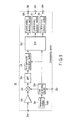
- FIG. 8 shows a first modification of the above embodiment. If FIG. 8 is explained with the same reference numerals given to the same components, in the tuner module 17, a BPF 19a for 38.9 MHz and a BPF 19b for 38.0 MHz are prepared. By using switches 25a, 25b selectable depending on the intermediate frequency setting signal, a necessary BPF 19a or 19b is used. Under such a structure, the same operation as the broadcast receiving apparatus 11 shown in FIG. 2 is carried out and the same effect can be obtained.
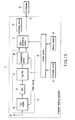
- FIG. 9 shows a second modification of the above embodiment. If FIG. 19 is explained with the same reference numerals given to the same components, in the tuner module 17, a single tuned circuit 26 for the IF signal frequency output from the tuner section 18 is connected between the tuner section 18 and the BPF 19.
- a carrier wave level of a channel adjacent to or second adjacent to a receiving channel is output from the tuner section 18 without being damped because the band of the SAW BPF18e is about 20 MHz, and then input to the demodulating section 20 through the BPF 19.
- the band characteristic of the IF signal outputted from the tuner section 18 is determined by a fore stage of the analog-to-digital converting section 20f in the demodulating section 20 on a post stage, the carrier of the adjacent channel is not damped so much in the preceding BPF 19.
- the band characteristic of the IF signal outputted from the tuner section 18 is determined by a fore stage of the analog-to-digital converting section 20f in the demodulating section 20 on a post stage, the carrier of the adjacent channel is not damped so much in the preceding BPF 19.
- the single tuned circuit 26 for the IF signal frequency between the tuner section 18 and the BPF 19 the signal levels of the adjacent channel and second adjacent channel can be suppressed, so that a performance resisting interference can be improved.
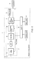
- FIG. 10 shows a third modification of the above embodiment. If FIG. 10 is explained with the same reference numerals given to the same components, in the tuner module 17, a trap filter 27, which is a channel upper second adjacent to a receiving channel, is connected between the BFF 19 and the demodulating section 20.
- the multi-wave signal is input to the tuner section 18 as described above, the levels of channels adjacent to and second adjacent to the receiving channel is output from the tuner section 18 without being damped because the band of the SAW BPF 18e is about 20 MHz, and then input to the demodulating section 20 through the BPF 19.
- the band characteristic of the IF signal output from the tuner section 18 is determined on a stage preceding the analog-to-digital converting section 20f in the demodulating section 20 on a post stage, the carrier of the adjacent channel is not damped so much in the preceding BPF 19. If the input IF signal is analog-to-digital converted under such a condition, the performance resisting interference in the vicinity of a channel upper second adjacent to the receiving channel is worsened by sampling distortion in the demodulating section 20.
- the trap filter 27 between the BPF 19 and the demodulating section 20 the signal component of the second adjacent channel can be suppressed, so that the performance resisting interference can be improved.
- FIG. 11 shows a fourth modification of the above embodiment. If FIG. 11 is explained with the same reference numerals given to the same components, a notch filter 28, which is a channel upper second adjacent to the receiving channel, is connected between the tuner section 18 and the BPF 19 in the tuner module 17. With such a structure, the signal component of the channel upper second adjacent to the receiving channel can be suppressed like the third modification, thereby making it possible to improve the performance resisting interference.
- FIG. 12 shows a fifth modification of the above embodiment. If FIG. 12 is explained with the same reference numerals given to the same components, a notch filter 29, which is a channel upper second adjacent to the receiving channel, is connected between the BPF 19 and the demodulating section 20 in the tuner module 17. With such a structure, the signal component of the channel upper second adjacent to the receiving channel can be suppressed like the third modification, thereby making it possible to improve the performance resisting interference.
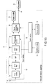
- FIG. 13 shows a sixth modification of the above embodiment. If FIG. 13 is explained with the same reference numerals given to the same components, notch filters 28, 29, which are a channel upper second adjacent to the receiving channel, are connected between the tuner section 18 and the BPF 19 and between the BPF 19 and the demodulating section 20, respectively, in the tuner module 17. With such a structure, the signal component of the channel upper second adjacent to the receiving channel can be suppressed like the third modification, thereby making it possible to improve the performance resisting interference.
- the above-mentioned tuner module 17 can be applied to a wide application field including the personal computer (PC) 30 shown in FIG. 14, the portable phone 31 shown in FIG. 15 and the like.
- PC personal computer
- the present invention is not restricted to the above-described embodiments but upon carrying out the invention, the components of the invention can be modified within a scope not departing from the gist of the invention. Further, by combining plural components disclosed in the above-described embodiments appropriately, various kinds of other inventions can be formed. For example, it is permissible to erase some components from the all components disclosed in the embodiments.
Landscapes
- Engineering & Computer Science (AREA)
- Multimedia (AREA)
- Signal Processing (AREA)
- Human Computer Interaction (AREA)
- Circuits Of Receivers In General (AREA)
- Superheterodyne Receivers (AREA)
Abstract
A broadcast receiving apparatus of the invention comprises a tuner section (18) which generates an intermediate frequency signal based on an intermediate frequency setting signal from a received broadcast signal, a filter section (19) which allows the generated intermediate frequency signal to pass through, a demodulating section (20) which carries out demodulation processing based on the intermediate frequency setting signal upon the intermediate frequency signal having passed through the filter section (19), and a control section (23) which, after information about a place in which the broadcast signal is received is input, reads an intermediate frequency setting signal stored in a memory (24) preliminarily corresponding to the place in which the information is input and supplies the signal to the tuner section (18) and the demodulating section (20).
Description
- The present invention relates to a broadcast receiving apparatus and broadcast receiving method for receiving, for example, analog TV broadcasts, and more particularly to a broadcast receiving apparatus and broadcast receiving method compatible with worldwide broadcast programs not limited to any particular country or region.
- As is well known, the intermediate frequencies of tuners for analog TV broadcasts are different depending on country and region because of legal restrictions. For example, in Europe, the US and Japan, the frequency is 38.9 MHz and in China and other Asian countries, it is 38.0 MHz.
- Thus, currently, tuner types handling each of the available intermediate frequencies are prepared, and a method of supplying a machine type compatible with a destination country and a method of selling a machine type corresponding to a user's region have been adopted.
- However, these methods have a problem in that the supply system of the tuner to users becomes complicated and users cannot use their purchased tuner if they bring it to a region whose intermediate frequency is different.
- Jpn. Pat. Appln. KOKAI Publication No. 2000-40977 discloses a frequency converter which converts intermediate frequency TV signals to low frequency using a mixer and Jpn. Pat. Appln. KOKAI Publication No. 9-205593 discloses a circuit which performs digital filtering an intermediate frequency video signal.
- However, there two publications describe nothing about a method for facilitating supply of the tuner to users to meet the fact that the intermediate frequency of the tuner must differ depending on the country or region.
- Accordingly, the present invention has been achieved in consideration of the above-described circumstances and an object of the present invention is to provide a broadcast receiving apparatus and a broadcast receiving method capable of handling different intermediate frequencies easily without the support of other devices and further facilitating the supply of the apparatus to users, thereby promoting practical use thereof.
- According to one aspect of the present invention, there is provided a broadcast receiving apparatus comprising: a receiving section configured to receive a broadcast signal; a tuner section configured to convert a frequency of the broadcast signal received by the receiving section into an intermediate frequency signal having a frequency designated by an intermediate frequency setting signal; a filter section configured to allow the intermediate frequency signal generated in the tuner section to pass through; a demodulating section configured to carry out demodulation of the intermediate frequency signal based on the intermediate frequency setting signal; a memory section configured to store information of the intermediate frequency setting signal corresponding to region where the receiving apparatus practicable; and a control section configured to read the information of the intermediate frequency setting signal corresponding to specific region from the memory section, the specific region is selected by a user, and supply the signal to the tuner section and the demodulating section.
- According to another aspect of the present invention, there is provided a broadcast receiving method comprising: a first step of receiving a broadcast signal; a second step of generating an intermediate frequency signal having a frequency based on an intermediate frequency setting signal from the received broadcast signal; a third step of allowing the generated intermediate frequency signal to pass through a filter; a fourth step of carrying out demodulation processing based on the intermediate frequency setting signal upon the intermediate frequency signal having passed through the filter; and a fifth step of, after inputting information about a place in which the broadcast signal is received, reading the intermediate frequency setting signal stored in a memory preliminarily corresponding to the place in which the information is input and applying the intermediate frequency setting signal to processing in the second and fourth steps.
- FIG. 1 is a perspective view of the appearance of a broadcast receiving apparatus according to an embodiment of the present invention;
- FIG. 2 is a block diagram for explaining the signal processing system of the broadcast receiving apparatus of the embodiment;
- FIG. 3 is a characteristic diagram for explaining the frequency characteristic of a band-pass filter of the broadcast receiving apparatus of the embodiment;
- FIG. 4 is a block diagram for explaining the details of a tuner section of the broadcast receiving apparatus of the embodiment;
- FIG. 5 is a block diagram for explaining the details of a demodulating section of the broadcast receiving apparatus of the embodiment;
- FIG. 6 is a flowchart for explaining an intermediate frequency setting operation of the broadcast receiving apparatus of the embodiment;
- FIG. 7 is a view for explaining an example of an intermediate frequency setting screen used in the intermediate frequency setting operation of the embodiment;
- FIG. 8 is a block diagram for explaining a first modification of the broadcast receiving apparatus of the embodiment;
- FIG. 9 is a block diagram for explaining a second modification of the broadcast receiving apparatus of the embodiment;
- FIG. 10 is a block diagram for explaining a third modification of the broadcast receiving apparatus of the embodiment;
- FIG. 11 is a block diagram for explaining a fourth modification of the broadcast receiving apparatus of the embodiment;
- FIG. 12 is a block diagram for explaining a fifth modification of the broadcast receiving apparatus of the embodiment;
- FIG. 13 is a block diagram for explaining a sixth modification of the broadcast receiving apparatus of the embodiment;
- FIG. 14 is a view for explaining a personal computer to which a tuner module of the embodiment is applied; and
- FIG. 15 is a view for explaining a portable phone to which the tuner module of the embodiment is applied.
- Hereinafter, an embodiment of the present invention will be described in detail with reference to the accompanying drawings. FIG. 1 shows the appearance of a
broadcast receiving apparatus 11 of the embodiment. Thebroadcast receiving apparatus 11 has a portable thin box-shaped case 12. - The
case 12 of thebroadcast receiving apparatus 11 has adisplay section 13 and anoperating section 14 on oneflat portion 12a thereof and aconnector 15 for audio output to be connected to a headphone or the like is provided on aside face 12b. - FIG. 2 shows a signal processing system of the
broadcast receiving apparatus 11. That is, a TV broadcast signal received by anantenna 16 incorporated in thecase 12 is supplied to atuner module 17. - The
tuner module 17 has atuner section 18, a band-pass filter (BPF) 19 and a demodulatingsection 20. Then, thetuner section 18 converts an inputted TV broadcasting signal to an intermediate frequency (IF) signal having a predetermined intermediate frequency and outputs to theBPF 19. - The
BPF 19 allows modulated wave components satisfying some extent of signal-to-noise ratio of the input IF signal to pass and outputs to the demodulatingsection 20. Then, the demodulatingsection 20 generates a base band video signal and audio signal before demodulation from the input IF signal. - In this way, the video signal and the audio signal outputted from the
tuner module 17 are supplied to asignal processing section 21. After converting the input video signal to a format suitable for representation on thedisplay section 13, thesignal processing section 21 outputs to thedisplay section 13 for representation. - The
signal processing section 21 executes demodulation processing on the inputted audio signal and then, outputs to headphones connected from outside through theconnector 15 for audio reproduction. - The
broadcast receiving apparatus 11 is controlled totally by acontrol section 23 about its all operations including the above-described receiving operation. Thecontrol section 23 incorporates a central processing unit (CPU) or the like, and receives operation information from theoperating section 14 in order to control the respective sections so that the content of that operation information is reflected thereon. - In this case, the
control section 23 uses amemory section 24. That is, thememory section 24 includes mainly a read only memory storing a control program to be executed by the CPU of thecontrol section 23, a read-out write memory which provides a work area to that CPU and a nonvolatile memory storing various kinds of setting information including intermediate frequency setting signal described later, control information and the like. - Here, as the
aforementioned tuner section 18, for example, a silicon tuner is used. Thetuner section 18 is capable of selectively setting the intermediate frequency of the IF signal to 38.9 MHz or 38.0 MHz based on the intermediate frequency setting signal supplied from thecontrol section 23 through, for example, a control bus such as IIC. - As the
BPF 19, for example, a digital demodulation surface acoustic wave (SAW) filter is used. TheBPF 19 allows the IF signals of two intermediate frequencies, 38.9 MHz and 38.0 MHz, to pass through as shown in FIG. 3. - Further, the
BPF 19 is set so that its frequency characteristic has no Nyquist slope characteristic so as to be able to supply modulated wave components satisfying some extent of signal-to-noise ratio to a demodulatingsection 20 located on a post stage. - In the demodulating
section 20, an internal clock is controlled so that demodulation processing corresponding to the IF signal of the intermediate frequency set by thetuner section 18 can be carried out from thecontrol section 23 based on the intermediate frequency setting signal supplied through a control bus such as IIC. - Because the
tuner module 17 is capable of meeting the IF signals of two intermediate frequencies, 38.0 MHz and 38.9 MHz, based on the intermediate frequency setting signal output from thecontrol section 23, thebroadcast receiving apparatus 11 can be supplied more easily to users and this is adaptable for practical use. - FIG. 4 shows the details of the
tuner section 18. That is, TV broadcast signal received by theantenna 16 is supplied to afrequency mixer 18c through aninput terminal 18a and again variable amplifier 18b. - The
frequency mixer 18c shifts input TV broadcast signal of 50-870 MHz to 1.2 GHz by mixing with local oscillation signal output from alocal oscillator 18d. - Then, a high frequency signal outputted from the
frequency mixer 18c is supplied to afrequency mixer 18f through a SAWBPF 18e. Thefrequency mixer 18f converts the input high-frequency signal to an IF signal of 38.9 MHz or 38.0 MHz by mixing with a local oscillation signal output from alocal oscillator 18g. - Thereafter, the IF signal output from the
frequency mixer 18f is fetched out from anoutput terminal 18k through anamplifier 18h, aSAW BPF 18i and anamplifier 18j and output to theBPF 19. - In the
local oscillators circuits reference oscillator 18n is supplied to thesePLL circuits - An intermediate frequency setting signal output from the
control section 23 is supplied to thePLL circuit 18m through a control terminal 18o. In thePLL circuit 18m, its division ratio is changed based on the intermediate frequency setting signal supplied from thecontrol section 23 and the frequency of a local oscillation signal output from thelocal oscillator 18g is changed based thereon. As a consequence, IF signals of 38.9 and 38.0 MHz can be selectively generated from thefrequency mixer 18f. - A gain adjustment signal output from the
demodulating section 20 is supplied to the gainvariable amplifier 18b through acontrol terminal 18p. In the gainvariable amplifier 18b, its gain is changed based on the gain adjustment signal output from thedemodulating section 20 and automatic gain adjustment of thetuner module 17 is carried out. - FIG. 5 shows the details of the
demodulating section 20. The IF signal of 38.9 or 38.0 MHz outputted from theBPF 19 is supplied to afrequency mixer 20c through aninput terminal 20a and anamplifier 20b. - The
frequency mixer 20c converts the inputted IF signal to a frequency operable with the digital signal processor (DSP) 20 located at a post stage by mixing with a clock signal output from aclock generating section 20d. - After passing a
BPF 20e, the IF signal output from thefrequency mixer 20c is digitized by an analog-to-digital converter 20f driven based on the clock signal output from theclock generating section 20d and supplied to aDSP 20g. - The
DSP 20g generates a gain adjustment signal to be given to the gainvariable amplifier 18b, video signal of baseband and audio signal prior to demodulation from the input IF signal based on the clock signal output from theclock generating section 20d. - Then, the gain control signal, after being converted to an analog signal by a digital-to-
analog converter 20h, is supplied to the gainvariable amplifier 18b through an output terminal 20i and thecontrol terminal 18p of thetuner section 18. - The video signal, after being converted to an analog signal by a digital-to-
analog converter 20j, is supplied to thesignal processing section 21 through anoutput terminal 20k. Further, the audio signal, after converted to an analog signal by a digital-to-analog converter 201, is supplied to thesignal processing section 21 through anoutput terminal 20m. - The
clock generating section 20d generates a clock signal based on a reference oscillation signal outputted from areference oscillator 20n. An intermediate frequency setting signal output from thecontrol section 23 is supplied to theclock generating section 20d through a control terminal 20o. - The
clock generating section 20d controls the frequency of the clock signal based on the intermediate frequency setting signal supplied from thecontrol section 23 so that the analog-to-digital converter 20f and theDSP 20g can execute analog-to-digital conversion processing and demodulation processing upon the IF signal of an intermediate frequency set by thetuner section 18. - Whether the intermediate frequency is set to 38.9 or 38.0 MHz can be set by a user when channel scanning of automatically retrieving a receivable channel by scanning a reception frequency band in succession continuously is demanded.
- FIG. 6 shows a flowchart summarizing the setting operation of the intermediate frequency. First, if the processing is started (step S1), the
control section 23 determines whether or not channel scan is requested in step S2 and if it is determined that the channel scan is not requested (NO), the processing is terminated (step S7). - If it is determined that the channel scan is requested in step S2 (YES), the
control section 23 indicates an intermediate frequency setting screen on thedisplay section 13 in step S3. The intermediate frequency setting screen lists regions and countries as shown in FIG. 7. - Then, a user selects a place where the
broadcast receiving apparatus 11 is to be used, that is, a region or country corresponding to the place where thebroadcast receiving apparatus 11 is currently installed from the listed regions and countries. The selection is carried out by moving a cursor k on the screen by operating theoperating section 14, and then operating a decision key. - Thereafter, the
control section 23 waits until a region or a country is selected from the intermediate frequency setting screen by the user in step S4, and if it is determined that a region or a country is selected (YES), an intermediate frequency setting signal corresponding to the intermediate frequency of the selected region or country is read out from thememory 24 in step S5 and output to thetuner section 18 and thedemodulating section 20. - Consequently, in the
tuner module 17, an intermediate frequency handled thereby is determined. If the intermediate frequency is determined in this way, thecontrol section 23 executes the channel scan in step S6 and terminates the processing (step S7). - According to the above-described embodiment, since the
tuner module 17 is capable of meeting the IF signals of two intermediate frequencies, 38.9 and 38.0 MHz, based on the intermediate frequency setting signal output from thecontrol section 23, the broadcast receiving apparatus can be supplied to users easily and the apparatus is adaptable for practical use. - FIG. 8 shows a first modification of the above embodiment. If FIG. 8 is explained with the same reference numerals given to the same components, in the
tuner module 17, aBPF 19a for 38.9 MHz and aBPF 19b for 38.0 MHz are prepared. By usingswitches necessary BPF broadcast receiving apparatus 11 shown in FIG. 2 is carried out and the same effect can be obtained. - FIG. 9 shows a second modification of the above embodiment. If FIG. 19 is explained with the same reference numerals given to the same components, in the
tuner module 17, a single tunedcircuit 26 for the IF signal frequency output from thetuner section 18 is connected between thetuner section 18 and theBPF 19. - That is, if a multi-wave signal is inputted to the
tuner section 18, a carrier wave level of a channel adjacent to or second adjacent to a receiving channel is output from thetuner section 18 without being damped because the band of the SAW BPF18e is about 20 MHz, and then input to thedemodulating section 20 through theBPF 19. - Although the band characteristic of the IF signal outputted from the
tuner section 18 is determined by a fore stage of the analog-to-digital converting section 20f in thedemodulating section 20 on a post stage, the carrier of the adjacent channel is not damped so much in the precedingBPF 19. When there exists a difference in signal level between the adjacent channel and the second adjacent channel, if the level of a reception signal is low with respect to a jamming wave, jamming by interference occurs. - To solve the problem, by connecting the single tuned
circuit 26 for the IF signal frequency between thetuner section 18 and theBPF 19, the signal levels of the adjacent channel and second adjacent channel can be suppressed, so that a performance resisting interference can be improved. - FIG. 10 shows a third modification of the above embodiment. If FIG. 10 is explained with the same reference numerals given to the same components, in the
tuner module 17, atrap filter 27, which is a channel upper second adjacent to a receiving channel, is connected between theBFF 19 and thedemodulating section 20. - If the multi-wave signal is input to the
tuner section 18 as described above, the levels of channels adjacent to and second adjacent to the receiving channel is output from thetuner section 18 without being damped because the band of theSAW BPF 18e is about 20 MHz, and then input to thedemodulating section 20 through theBPF 19. - Although the band characteristic of the IF signal output from the
tuner section 18 is determined on a stage preceding the analog-to-digital converting section 20f in thedemodulating section 20 on a post stage, the carrier of the adjacent channel is not damped so much in the precedingBPF 19. If the input IF signal is analog-to-digital converted under such a condition, the performance resisting interference in the vicinity of a channel upper second adjacent to the receiving channel is worsened by sampling distortion in thedemodulating section 20. - To solve the problem, by connecting the
trap filter 27 between theBPF 19 and thedemodulating section 20, the signal component of the second adjacent channel can be suppressed, so that the performance resisting interference can be improved. - FIG. 11 shows a fourth modification of the above embodiment. If FIG. 11 is explained with the same reference numerals given to the same components, a
notch filter 28, which is a channel upper second adjacent to the receiving channel, is connected between thetuner section 18 and theBPF 19 in thetuner module 17. With such a structure, the signal component of the channel upper second adjacent to the receiving channel can be suppressed like the third modification, thereby making it possible to improve the performance resisting interference. - FIG. 12 shows a fifth modification of the above embodiment. If FIG. 12 is explained with the same reference numerals given to the same components, a
notch filter 29, which is a channel upper second adjacent to the receiving channel, is connected between theBPF 19 and thedemodulating section 20 in thetuner module 17. With such a structure, the signal component of the channel upper second adjacent to the receiving channel can be suppressed like the third modification, thereby making it possible to improve the performance resisting interference. - FIG. 13 shows a sixth modification of the above embodiment. If FIG. 13 is explained with the same reference numerals given to the same components,
notch filters tuner section 18 and theBPF 19 and between theBPF 19 and thedemodulating section 20, respectively, in thetuner module 17. With such a structure, the signal component of the channel upper second adjacent to the receiving channel can be suppressed like the third modification, thereby making it possible to improve the performance resisting interference. - The above-mentioned
tuner module 17 can be applied to a wide application field including the personal computer (PC) 30 shown in FIG. 14, theportable phone 31 shown in FIG. 15 and the like. - In the meantime, the present invention is not restricted to the above-described embodiments but upon carrying out the invention, the components of the invention can be modified within a scope not departing from the gist of the invention. Further, by combining plural components disclosed in the above-described embodiments appropriately, various kinds of other inventions can be formed. For example, it is permissible to erase some components from the all components disclosed in the embodiments.
Claims (14)
- A broadcast receiving apparatus characterized by comprising:a receiving section (16) configured to receive a broadcast signal;a tuner section (18) configured to convert a frequency of the broadcast signal received by the receiving section (16) into an intermediate frequency signal having a frequency designated by an intermediate frequency setting signal;a filter section (19) configured to allow the intermediate frequency signal generated in the tuner section (18) to pass through;a demodulating section (20) configured to carry out demodulation of the intermediate frequency signal based on the intermediate frequency setting signal;a memory section (24) configured to store information of the intermediate frequency setting signal corresponding to region where the receiving apparatus practicable; anda control section (23) configured to read the information of the intermediate frequency setting signal corresponding to specific region from the memory section (24), the specific region is selected by a user, and supply the signal to the tuner section (18) and the demodulating section (20).
- The broadcast receiving apparatus according to claim 1, characterized in that the tuner section (18) comprises:a first converting section (18c) configured to mix the broadcast signal received by the receiving section (16) with a first local oscillation signal to convert to a signal having a frequency higher than the broadcast signal;a second converting section (18f) configured to mix the signal output from the first converting section (18c) with a second local oscillation signal to convert to an intermediate frequency signal having a frequency lower than the broadcast signal; anda frequency changing section (18m) configured to change the frequency of the second local oscillation signal used in the second converting section (18f) based on the intermediate frequency setting signal.
- The broadcast receiving apparatus according to claim 1, characterized in that the demodulating section (20) comprises:a third converting section (20c) configured to mix the intermediate frequency signal output from the filter section (19) with a clock signal to convert to a signal having a predetermined frequency;an analog-to-digital converting section (20f) configured to digitize the signal output from the third converting section (20c) based on the clock signal;a demodulating section (20g) configured to carry out demodulation processing upon the signal output from the analog-to-digital converting section (20f) based on the clock signal; anda clock signal frequency changing section (20d) configured to change the frequency of the clock signal based on the intermediate frequency setting signal.
- The broadcast receiving apparatus according to claim 1, characterized in that the filter section (19) is a SAW filter having a frequency characteristic of allowing intermediate frequency signals of all frequencies which are outputted from the tuner section (18) to pass through such that a predetermined signal-to-noise ratio is satisfied.
- The broadcast receiving apparatus according to claim 1, characterized in that the filter section (19) comprises:a plurality of filters (19a, 19b) configured to allow the intermediate frequency signals of all frequencies which are output from the tuner section (18) to pass through; andswitches (25a, 25b) configured to selectively connect the plurality of filters (19a, 19b) between the tuner section (18) and the demodulating section (20) based on the intermediate frequency setting signal.
- The broadcast receiving apparatus according to claim 1, characterized in that the control section (23) comprises:a display control section (23) configured to display an intermediate frequency setting screen listing plural regions or countries;an operating section (14) configured to select and determine a predetermined region or country on the intermediate frequency setting screen displayed based on the display control section (23); anda generating section (24) configured to generate an intermediate frequency setting signal corresponding to a predetermined region or country selected and determined by the operating section (14).
- The broadcast receiving apparatus according to claim 1, characterized in that the control section (23) is configured to input information corresponding to a place in which the broadcast signal is received when channel scan is requested.
- The broadcast receiving apparatus according to claim 1, characterized in that the intermediate frequency setting signal corresponds to any one of intermediate frequency signals of 38.0 and 38.9 MHz.
- The broadcast receiving apparatus according to claim 1, characterized in that a single tuned circuit (26) for the intermediate frequency signal generated by the tuner section (18) is connected between the tuner section (18) and the filter section (19).
- The broadcast receiving apparatus according to claim 1, characterized in that a trap filter (27), which is a channel upper second adjacent to a receiving channel, is connected between the filter section (19) and the demodulating section (20).
- The broadcast receiving apparatus according to claim 1, characterized in that notch filters (28, 29), which are a channel upper second adjacent to a receiving channel, are connected between the tuner section (18) and the filter section (19) and/or between the filter section (19) and the demodulating section (20).
- A tuner module characterized by comprising:a receiving section (16) configured to receive a broadcast signal;a tuner section (18) configured to generate an intermediate frequency signal having a frequency based on an intermediate frequency setting signal supplied from outside from the broadcast signal received by the receiving section (16);a filter section (19) configured to allow the intermediate frequency signal generated by the tuner section (18) to pass through; anda demodulating section (20) configured to carry out demodulation processing based on the intermediate frequency setting signal supplied from outside upon the intermediate frequency signal having passed through the filter section (19).
- A broadcast receiving method characterized by comprising:a first step (16) of receiving a broadcast signal;a second step (18) of generating an intermediate frequency signal having a frequency based on an intermediate frequency setting signal from the received broadcast signal;a third step of allowing the generated intermediate frequency signal to pass a filter (19);a fourth step (20) of carrying out demodulation processing based on the intermediate frequency setting signal upon the intermediate frequency signal having passed through the filter (19); anda fifth step (23) of, after inputting information about a place in which the broadcast signal is received, reading the intermediate frequency setting signal stored in a memory (24) preliminarily corresponding to the place in which the information is input and applying the intermediate frequency setting signal to processing in the second and fourth steps (18, 20).
- The broadcast receiving method according to claim 13, characterized in that the fifth step (23) comprises:steps (23, S2, S3) of displaying an intermediate frequency setting screen listing plural regions or countries when channel scan is requested;steps (14, S4) of executing an operation for selecting and determining a predetermined region or country on the displayed intermediate frequency setting screen; andsteps (24, S5) of generating an intermediate frequency setting signal corresponding to a predetermined region or country selected and determined.
Applications Claiming Priority (3)
| Application Number | Priority Date | Filing Date | Title |
|---|---|---|---|
| JP2004194310 | 2004-06-30 | ||
| JP2004229723 | 2004-08-05 | ||
| JP2004381560A JP2006074718A (en) | 2004-06-30 | 2004-12-28 | Broadcast receiving apparatus and broadcast receiving method |
Publications (1)
| Publication Number | Publication Date |
|---|---|
| EP1613064A1 true EP1613064A1 (en) | 2006-01-04 |
Family
ID=35058988
Family Applications (1)
| Application Number | Title | Priority Date | Filing Date |
|---|---|---|---|
| EP05105825A Withdrawn EP1613064A1 (en) | 2004-06-30 | 2005-06-29 | Broadcast receiving apparatus and broadcast receiving method |
Country Status (3)
| Country | Link |
|---|---|
| US (1) | US20060003718A1 (en) |
| EP (1) | EP1613064A1 (en) |
| JP (1) | JP2006074718A (en) |
Cited By (1)
| Publication number | Priority date | Publication date | Assignee | Title |
|---|---|---|---|---|
| WO2009118669A3 (en) * | 2008-03-26 | 2009-11-19 | Nxp B.V. | Method and apparatus for processing an analog intermediate frequency television signal |
Families Citing this family (8)
| Publication number | Priority date | Publication date | Assignee | Title |
|---|---|---|---|---|
| US20040258179A1 (en) * | 2003-06-20 | 2004-12-23 | Long Jerral A. | RF receiver and method for region specific data selection |
| JP2005079677A (en) * | 2003-08-28 | 2005-03-24 | Sanyo Electric Co Ltd | Signal processing circuit for tuner |
| JP2007324951A (en) * | 2006-06-01 | 2007-12-13 | Sony Corp | Receiver |
| US8326248B2 (en) * | 2006-07-28 | 2012-12-04 | Panasonic Corporation | Analog radio receiver |
| US20080119148A1 (en) * | 2006-11-16 | 2008-05-22 | William Martin Ray | Radio receiver and method of dynamically setting tuning parameters based on location |
| JP4887242B2 (en) * | 2007-08-30 | 2012-02-29 | オンセミコンダクター・トレーディング・リミテッド | Intermediate frequency filter band switching control device |
| WO2011021252A1 (en) * | 2009-08-21 | 2011-02-24 | 三菱電機株式会社 | Radio broadcast receiver |
| JP2017028480A (en) * | 2015-07-22 | 2017-02-02 | 船井電機株式会社 | Receiver |
Citations (4)
| Publication number | Priority date | Publication date | Assignee | Title |
|---|---|---|---|---|
| EP0963110A2 (en) * | 1998-06-06 | 1999-12-08 | Micronas Intermetall GmbH | Frequency conversion arrangement for a composite television signal |
| US6340997B1 (en) * | 1998-04-08 | 2002-01-22 | Microsoft Corporation | Worldwide television tuning system with object-based tuning control modules |
| US20020008787A1 (en) * | 2000-07-19 | 2002-01-24 | Tadao Kurihara | Television receiving apparatus |
| US20040061804A1 (en) * | 2001-09-17 | 2004-04-01 | Pierre Favrat | Broadband receiver having a multistandard channel filter |
Family Cites Families (1)
| Publication number | Priority date | Publication date | Assignee | Title |
|---|---|---|---|---|
| FR2742956B1 (en) * | 1995-12-22 | 1998-01-30 | Thomson Multimedia Sa | CIRCUIT FOR PERFORMING DIGITAL NYQUIST FILTERING OF INTERMEDIATE FREQUENCY SIGNALS |
-
2004
- 2004-12-28 JP JP2004381560A patent/JP2006074718A/en active Pending
-
2005
- 2005-06-29 EP EP05105825A patent/EP1613064A1/en not_active Withdrawn
- 2005-06-29 US US11/169,291 patent/US20060003718A1/en not_active Abandoned
Patent Citations (4)
| Publication number | Priority date | Publication date | Assignee | Title |
|---|---|---|---|---|
| US6340997B1 (en) * | 1998-04-08 | 2002-01-22 | Microsoft Corporation | Worldwide television tuning system with object-based tuning control modules |
| EP0963110A2 (en) * | 1998-06-06 | 1999-12-08 | Micronas Intermetall GmbH | Frequency conversion arrangement for a composite television signal |
| US20020008787A1 (en) * | 2000-07-19 | 2002-01-24 | Tadao Kurihara | Television receiving apparatus |
| US20040061804A1 (en) * | 2001-09-17 | 2004-04-01 | Pierre Favrat | Broadband receiver having a multistandard channel filter |
Cited By (1)
| Publication number | Priority date | Publication date | Assignee | Title |
|---|---|---|---|---|
| WO2009118669A3 (en) * | 2008-03-26 | 2009-11-19 | Nxp B.V. | Method and apparatus for processing an analog intermediate frequency television signal |
Also Published As
| Publication number | Publication date |
|---|---|
| US20060003718A1 (en) | 2006-01-05 |
| JP2006074718A (en) | 2006-03-16 |
Similar Documents
| Publication | Publication Date | Title |
|---|---|---|
| TWI596947B (en) | Television receiver for digital and analog television signals | |
| US7831198B2 (en) | Broadcast receiving apparatus | |
| US7808419B2 (en) | Digitizer with variable sampling clock and method using the same | |
| US20060003718A1 (en) | Broadcast receiving apparatus and broadcast receiving method | |
| TWI288565B (en) | Integrated circuit for a mobile television receiver | |
| JPH11112462A (en) | Digital broadcast receiver | |
| JP4935532B2 (en) | Digital broadcast demodulating device and digital broadcast demodulating method | |
| JP2008502278A (en) | Apparatus and method for processing signals in a multi-channel receiver | |
| US20050090207A1 (en) | Diversity reception tuner | |
| GB2325804A (en) | Combined satellite and CATV receiver | |
| JPWO2014199543A1 (en) | Television receiving apparatus and television receiving method | |
| JP2005269506A (en) | Broadcast receiving apparatus and broadcast receiving processing program | |
| JPH11205172A (en) | Tuner for satellite broadcasting receiver | |
| US7145610B2 (en) | Receiving method and apparatus of analog television signals technical field | |
| JP2006148533A (en) | Audio intermediate frequency conversion circuit | |
| JP2007116429A (en) | Broadcast receiver | |
| CN1770837A (en) | Broadcast receiving apparatus and broadcast receiving method | |
| JP2007281653A (en) | Semiconductor integrated circuit, TV broadcast receiving apparatus and TV broadcast receiving method | |
| JP2008263307A (en) | Broadcast receiving apparatus and broadcast receiving method | |
| JPH06133317A (en) | Tuner device | |
| JP2005079698A (en) | Tuning device | |
| JP2003133986A (en) | Digital broadcast receiver | |
| JP2008533941A (en) | Filter device, circuit device comprising such a filter device and method for operating such a filter device | |
| JP2006520549A (en) | Digital tuner | |
| JP4134099B2 (en) | Television broadcast receiver |
Legal Events
| Date | Code | Title | Description |
|---|---|---|---|
| PUAI | Public reference made under article 153(3) epc to a published international application that has entered the european phase |
Free format text: ORIGINAL CODE: 0009012 |
|
| 17P | Request for examination filed |
Effective date: 20050630 |
|
| AK | Designated contracting states |
Kind code of ref document: A1 Designated state(s): AT BE BG CH CY CZ DE DK EE ES FI FR GB GR HU IE IS IT LI LT LU MC NL PL PT RO SE SI SK TR |
|
| AX | Request for extension of the european patent |
Extension state: AL BA HR LV MK YU |
|
| AKX | Designation fees paid |
Designated state(s): DE FR GB |
|
| STAA | Information on the status of an ep patent application or granted ep patent |
Free format text: STATUS: THE APPLICATION IS DEEMED TO BE WITHDRAWN |
|
| 18D | Application deemed to be withdrawn |
Effective date: 20061024 |