EP1613059A1 - Apparatus and method for processing video signal - Google Patents
Apparatus and method for processing video signal Download PDFInfo
- Publication number
- EP1613059A1 EP1613059A1 EP05104628A EP05104628A EP1613059A1 EP 1613059 A1 EP1613059 A1 EP 1613059A1 EP 05104628 A EP05104628 A EP 05104628A EP 05104628 A EP05104628 A EP 05104628A EP 1613059 A1 EP1613059 A1 EP 1613059A1
- Authority
- EP
- European Patent Office
- Prior art keywords
- unit
- signal
- processing
- video signal
- contour correction
- Prior art date
- Legal status (The legal status is an assumption and is not a legal conclusion. Google has not performed a legal analysis and makes no representation as to the accuracy of the status listed.)
- Withdrawn
Links
- 238000000034 method Methods 0.000 title claims description 15
- 230000001934 delay Effects 0.000 claims abstract description 9
- 238000011084 recovery Methods 0.000 claims description 8
- 238000000926 separation method Methods 0.000 claims description 7
- 238000010586 diagram Methods 0.000 description 5
- 230000002708 enhancing effect Effects 0.000 description 4
- 230000003111 delayed effect Effects 0.000 description 2
- 230000000694 effects Effects 0.000 description 2
- 230000001771 impaired effect Effects 0.000 description 2
- 239000004973 liquid crystal related substance Substances 0.000 description 1
- 230000004044 response Effects 0.000 description 1
Images




Classifications
-
- H—ELECTRICITY
- H04—ELECTRIC COMMUNICATION TECHNIQUE
- H04N—PICTORIAL COMMUNICATION, e.g. TELEVISION
- H04N5/00—Details of television systems
- H04N5/14—Picture signal circuitry for video frequency region
- H04N5/20—Circuitry for controlling amplitude response
- H04N5/205—Circuitry for controlling amplitude response for correcting amplitude versus frequency characteristic
- H04N5/208—Circuitry for controlling amplitude response for correcting amplitude versus frequency characteristic for compensating for attenuation of high frequency components, e.g. crispening, aperture distortion correction
Definitions
- the present invention relates to an apparatus and a method for processing a video signal for displaying a video signal onto such as a flat panel type display, and specifically, relates to an improvement in a horizontal contour correction for the apparatus and the method related thereto.
- Such a display apparatus performs contour correction processing to enhance its contour component for an input video signal.
- a technique to extract a contour component of a brightness signal and vary a contour correction amount in response to its amplitude width is disclosed in Jpn. Pat. Appln. KOKAI Publication No. 11-243496.
- an object of the present invention is to provide an apparatus and a method for processing a video signal capable of practically conducting a contour correction without impairing a delicacy of a pattern made as a video display.
- an apparatus for processing a video signal comprises a receiving unit which receives a broadcast signal, a recovery processing unit which recovers a video signal from the broadcast signal received by the receiving unit, a first contour correction unit which performs contour correction processing on the video signal recovered by the recovery processing unit, a first delay unit which delays the video signal recovered by the recovery processing unit by the time required for the contour correction processing performed by the first contour correction unit, a first adder unit which adds an output signal from the first delay unit to an output signal from the contour correction unit, a nonlinear processing unit which performs nonlinear processing on an output signal from the first adder unit, a separation unit which separates a signal component with not more than a prescribed amplitude level from a contour component of the video signal recovered by the recovery processing unit, a second contour correction unit which performs contour correction processing on a signal with not more than the prescribed amplitude level separated by the separation unit, a second delay unit which delays an output signal from the second contour correction unit by the time required for the nonlinear
- a method for processing a video signal comprises a first step of receiving a video signal, a second step of performing contour correction processing on the received video signal, a third step of delaying the signal by the time required for the contour correction processing in the second step, a fourth step of adding an output signal from the third step and an output signal from the second step, a fifth step of performing nonlinear processing on an output signal from the fourth step, a sixth step of separating a signal component with not more than a prescribed amplitude level from a contour component of the video signal received in the first step, an seventh step of performing contour correction processing on a signal with not more than the prescribed amplitude level separated in the sixth step, a eighth step of delaying an output signal from the seventh step by the time required for the nonlinear processing in the fifth step, and a ninth step of adding an output signal from the eighth step to the output signal from the seventh step.
- the embodiment according to the invention described above separates the contour component of the received video signal into a signal with high amplitude level and a signal with a minute amplitude level, performs the nonlinear processing after the contour correction processing on the signal with the high amplitude level, and performs only the contour correction processing on the signal with the minute amplitude level. Since the embodiment of the invention does not perform the nonlinear processing on the signal with the minute amplitude level after performing the contour correction processing, a minute amplitude level component of the video signal can be prevented from being compressed by the nonlinear processing and the delicacy of the pattern made in the video display can be prevented from being impaired.
- FIG. 1 and FIG. 2 show a front view and a side view of a TV receiving apparatus 11 of a flat panel type which will be explained in this embodiment, respectively.
- the TV receiving apparatus 11 is composed of mainly a cabinet 12, a support base 13 to support the cabinet 12.
- a front center part of the cabinet 12 is provided with a display panel 14a of a later-mentioned video display unit 14.
- a housing unit 12a with a later-mentioned signal processing system housed therein is disposed on the rear side of the cabinet 12.
- the support base 13 is rotatably connected to a rear central part of the cabinet 12 and configured to make the cabinet 12 stand rise in a state that the support base 13 is mounted on a horizontal surface of a prescribed base stand 17.
- FIG. 3 shows the signal processing system of the TV receiving apparatus 11. That is, a TV broadcast signal received via an antenna 18 is supplied to a channel unit 20 through an input terminal 19 and a broadcast signal of a prescribed channel is tuned.
- the broadcast signal output from the tuner unit 20 is supplied to a frequency converter 21 to be converted into an intermediate signal, then, recovered to a digital video signal by means of a digital signal processing unit 22, and supplied to a selector 23.
- the TV receiving apparatus 11 receives a video signal generated in a component format or an RGB format from an external arbitrary source via an input terminal 24.
- the video signal supplied to the input terminal 24 is supplied to an analog/digital (A/D) converter 25 to be converted into a digital signal then supplied to the selector 23.
- A/D analog/digital
- the selector 23 selectively outputs two kinds of video signals to be input, to a scaling unit 26.
- the scaling unit 26 performs scaling processing of the input video signal so as to match the number of pixels of the input video signal to the number of the pixels of the display panel 14a of the video display unit 14 to output the processed video signal to a video processing unit 27.
- the video processing unit 27 performs processing of the input video signal so as to make a video display on the video display unit 14. Then, the video signal output from the video processing unit 27 is supplied to the video display unit 14 via a driver 28 to enable video display.
- control unit 29 incorporates a central processing unit (CPU) (not shown), etc., receives operation information from an operation unit 30 including a power switch 15, or receives operation information transmitted from a remote controller 31 through the receiving unit 16 and respectively controls each unit so that operation contents in the operation information are reflected.
- CPU central processing unit
- control unit 29 utilizes a memory unit 32.
- the memory unit 32 is composed of mainly a dedicated memory (not shown) with a control program to be executed by a CPU in the control unit 29 stored therein, a read/write memory (not shown) to provide a working area for the CPU, and a nonvolatile memory (not shown) in which a variety of setting information and control information, etc. is stored.
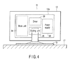
- FIG. 4 shows a rear view of the TV receiving apparatus.
- the driver 28 and the scaling unit 26 are disposed at its center part, a power unit 33 is disposed on the right side in FIG. 4, and a block unit 34 including the other units is disposed on the left side in FIG. 4.
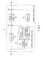
- FIG. 5 shows a horizontal contour correction unit 35 disposed inside the video processing unit 27.
- a digitalized brightness signal is supplied to the correction unit 35 via an input terminal 35a, as a video signal output from a scaling unit 26.
- the brightness signal supplied to the input terminal 35a is supplied to a delay circuit 35b and an amplitude discrimination circuit composing a horizontal contour correction circuit 35cl.
- the discrimination circuit 35cl separates the contour component of the input brightness signal into a signal component with a minute amplitude level and other than a signal component with a high amplitude level.
- the separated signal component with the high amplitude level is supplied to a contour correction circuit 35c2, configured to have effect for the signal with the high amplitude level, where contour correction processing such as contour enhancing is processed on the signal component.
- the delay circuit 35b delays the input brightness signal by the time required to the contour correction processing by the correction circuit 35c2.
- the brightness signal delayed by the delay circuit 35b and the brightness signal processed the contour correction processing are supplied to an adder circuit 35d to be added with each other.
- the brightness signal output from the adder circuit 35d is supplied to a nonlinear processing circuit 35e and is processed by nonlinear processing, for example, gamma correction.
- the signal component with the minute amplitude level separated by the amplitude discrimination circuit 35c1 is supplied to a minute amplitude contour correction circuit 35c3, designed to have effect for the signal with the minute amplitude level, where contour correction processing such as contour enhancing is processed on the signal component. Then, the processed signal component is supplied to a delay circuit 35f.
- the delay circuit 35f delays the input brightness signal by the time required for the nonlinear processing by the nonlinear processing circuit 35e.
- An adder circuit 35g adds the brightness signal delayed through the delay circuit 35f to the brightness signal processed by the nonlinear processing through the nonlinear processing circuit 35e thereto, and an output terminal 35h outputs the added brightness signal.
- the above-mentioned horizontal contour correction unit 35 separates the input brightness signal into the signal component with the high amplitude level and the signal component with the minute amplitude level.
- the correction unit 35 performs the nonlinear processing after performing the contour correction processing for the signal component with the high amplitude level, and performs only the contour correction processing for the signal component with the minute amplitude level.
- the correction unit 35 does not perform the nonlinear processing after performing the contour correction processing on the signal component with the minute amplitude level, so that the minute amplitude level component of the brightness signal is prevented from being compressed by the nonlinear processing and the delicacy of the pattern of the displayed video can be prevented from being impaired.
- FIG. 6 shows the flowchart as a whole of operations of the correction unit 35.
- the amplitude discrimination circuit 35c1 separates the input brightness signal into the signal component with the minute amplitude level and other signal component with the high amplitude level (step S2).
- the contour correction circuit 35c2 performs the contour correction processing such as contour enhancing on the signal component with the high amplitude level (step S3), and the adder circuit 35d adds the output from the contour correction circuit 35c2 to the output from the delay circuit 35b to delay the input brightness signal by the time necessary for the contour correction processing by the correction circuit 35c2 (step S4).
- the nonlinear processing circuit 35e performs the nonlinear processing on the output from the adder circuit 35d (step S5).
- the minute amplitude contour correction circuit 35c3 performs the contour correction processing such as contour enhancing on the signal component with the minute amplitude level (step 6).
- the adder circuit 35g adds the output from the nonlinear processing circuit 35e to the output from the delay circuit 35f to delay the output from the contour correction circuit 35c3 by the time needed for the nonlinear processing carried out by the nonlinear processing circuit 35e, then, the processing is terminated (step S8).
- the invention is not limited to such an example, and it is possible to be adopted to, for example, an STB or a PDA.
- FIG. 7 shows a block diagram of an STB 36.
- the STB 36 will be explained by referring to the same symbols for the same parts as those of FIG. 3.
- the video signal generated from the video processing unit 27 can be output through an output terminal 37.
- a flat panel display 40 equipped with a driver 38 and a video display unit 39 displays the video signal output through the output terminal 37, as the video display.
- FIG. 8 shows a PDA 41.
- the PDA 41 will be explained by referring to the same symbols for the same parts as those of FIG. 3.
- the PDA 41 becomes a mobile information terminal which is not provided with the antenna 18, the input terminal 19, the tuner unit 20, the frequency converter 21, the digital signal processing unit 22, the selector 23, the receiving unit 16, and the like.
Landscapes
- Engineering & Computer Science (AREA)
- Multimedia (AREA)
- Signal Processing (AREA)
- Picture Signal Circuits (AREA)
- Control Of Indicators Other Than Cathode Ray Tubes (AREA)
Abstract
An amplitude discrimination circuit (35c1) separates a received video signal into a signal component with a minute amplitude level and other signal component with a high amplitude level. A contour correction circuit (35c2) performs contour correction processing on a signal with the high amplitude level and a nonlinear processing circuit (35e) performs nonlinear processing after adding the signal with high amplitude level to an output from a delay circuit (33d) which delays the received video signal by the time required for the contour correction processing performed by the contour correction circuit (35c2). A minute amplitude contour correction circuit (35c3) performs contour correction processing on the signal with the minute amplitude level and an adder circuit (35g) adds the signal with the minute amplitude level to an output from the nonlinear processing circuit (35e) after delaying the signal with the minute amplitude level by the time required for the nonlinear processing performed by a delay circuit (35f).
Description
- The present invention relates to an apparatus and a method for processing a video signal for displaying a video signal onto such as a flat panel type display, and specifically, relates to an improvement in a horizontal contour correction for the apparatus and the method related thereto.
- In recent years, a flat panel type display using, for example, a liquid crystal panel or a plasma display panel has become widely used. For this kind of display, a video projection type, or so-called projector tends to become widely used.
- Incidentally, in such a display apparatus performs contour correction processing to enhance its contour component for an input video signal. A technique to extract a contour component of a brightness signal and vary a contour correction amount in response to its amplitude width is disclosed in Jpn. Pat. Appln. KOKAI Publication No. 11-243496.
- However, the technique for performing the contour correction processing to a video signal has not developed perfectly and has been sill in a developing stage, and it is therefore strongly desired for a method further appropriate for practical use to be developed, in respect of a variety of points.
- In viewing of the foregoing, an object of the present invention is to provide an apparatus and a method for processing a video signal capable of practically conducting a contour correction without impairing a delicacy of a pattern made as a video display.
- According to an embodiment of the present invention, an apparatus for processing a video signal comprises a receiving unit which receives a broadcast signal, a recovery processing unit which recovers a video signal from the broadcast signal received by the receiving unit, a first contour correction unit which performs contour correction processing on the video signal recovered by the recovery processing unit, a first delay unit which delays the video signal recovered by the recovery processing unit by the time required for the contour correction processing performed by the first contour correction unit, a first adder unit which adds an output signal from the first delay unit to an output signal from the contour correction unit, a nonlinear processing unit which performs nonlinear processing on an output signal from the first adder unit, a separation unit which separates a signal component with not more than a prescribed amplitude level from a contour component of the video signal recovered by the recovery processing unit, a second contour correction unit which performs contour correction processing on a signal with not more than the prescribed amplitude level separated by the separation unit, a second delay unit which delays an output signal from the second contour correction unit by the time required for the nonlinear processing performed by the nonlinear processing unit, and a second adder unit which adds an output signal form the second delay unit to an output signal from the nonlinear processing unit.
- According to an another embodiment of the present invention, a method for processing a video signal comprises a first step of receiving a video signal, a second step of performing contour correction processing on the received video signal, a third step of delaying the signal by the time required for the contour correction processing in the second step, a fourth step of adding an output signal from the third step and an output signal from the second step, a fifth step of performing nonlinear processing on an output signal from the fourth step, a sixth step of separating a signal component with not more than a prescribed amplitude level from a contour component of the video signal received in the first step, an seventh step of performing contour correction processing on a signal with not more than the prescribed amplitude level separated in the sixth step, a eighth step of delaying an output signal from the seventh step by the time required for the nonlinear processing in the fifth step, and a ninth step of adding an output signal from the eighth step to the output signal from the seventh step.
- The embodiment according to the invention described above separates the contour component of the received video signal into a signal with high amplitude level and a signal with a minute amplitude level, performs the nonlinear processing after the contour correction processing on the signal with the high amplitude level, and performs only the contour correction processing on the signal with the minute amplitude level. Since the embodiment of the invention does not perform the nonlinear processing on the signal with the minute amplitude level after performing the contour correction processing, a minute amplitude level component of the video signal can be prevented from being compressed by the nonlinear processing and the delicacy of the pattern made in the video display can be prevented from being impaired.
- This summary of the invention does not necessarily describe all necessary features so that the invention may also be a sub-combination of these described features.
- The invention can be more fully understood from the following detailed description when taken in conjunction with the accompanying drawings, in which:
- FIG. 1 is a view showing an embodiment of the invention and a front elevation view for explaining an external appearance of a television (TV) receiving apparatus;
- FIG. 2 is a side elevation view for explaining the external appearance of the TV receiving apparatus in the embodiment;
- FIG. 3 is a block diagram for explaining a signal processing system of the TV receiving apparatus in the embodiment;
- FIG. 4 is a rear elevation view for explaining the appearance of the TV receiving apparatus in the embodiment;
- FIG. 5 is a block diagram for explaining the details of a horizontal contour correction unit used for a video processing unit of the TV receiving apparatus in the embodiment;
- FIG. 6 is a flowchart for explaining main operations of a horizontal contour correction unit of the TV receiving apparatus in the embodiment;
- FIG. 7 is a block diagram for explaining an example of a set top box (STB) with the invention adopted thereto; and
- FIG. 8 is a block diagram for explaining an example of a personal digital assistant (PDA).
- Hereinafter, the details of an embodiment of the present invention will be explained by referring drawings. FIG. 1 and FIG. 2 show a front view and a side view of a
TV receiving apparatus 11 of a flat panel type which will be explained in this embodiment, respectively. - The
TV receiving apparatus 11 is composed of mainly acabinet 12, asupport base 13 to support thecabinet 12. A front center part of thecabinet 12 is provided with adisplay panel 14a of a later-mentionedvideo display unit 14. - On the both sides of the
display panel 14a of thecabinet 12 is provided apower switch 15 and a receivingunit 16 for receiving operation information transmitted from a wireless remote controller (not shown). Moreover, ahousing unit 12a with a later-mentioned signal processing system housed therein is disposed on the rear side of thecabinet 12. - On the other hand, the
support base 13 is rotatably connected to a rear central part of thecabinet 12 and configured to make thecabinet 12 stand rise in a state that thesupport base 13 is mounted on a horizontal surface of a prescribedbase stand 17. - FIG. 3 shows the signal processing system of the
TV receiving apparatus 11. That is, a TV broadcast signal received via anantenna 18 is supplied to achannel unit 20 through aninput terminal 19 and a broadcast signal of a prescribed channel is tuned. - The broadcast signal output from the
tuner unit 20 is supplied to afrequency converter 21 to be converted into an intermediate signal, then, recovered to a digital video signal by means of a digitalsignal processing unit 22, and supplied to aselector 23. - Meantime, the
TV receiving apparatus 11 receives a video signal generated in a component format or an RGB format from an external arbitrary source via aninput terminal 24. The video signal supplied to theinput terminal 24 is supplied to an analog/digital (A/D)converter 25 to be converted into a digital signal then supplied to theselector 23. - The
selector 23 selectively outputs two kinds of video signals to be input, to ascaling unit 26. Thescaling unit 26 performs scaling processing of the input video signal so as to match the number of pixels of the input video signal to the number of the pixels of thedisplay panel 14a of thevideo display unit 14 to output the processed video signal to avideo processing unit 27. - The
video processing unit 27 performs processing of the input video signal so as to make a video display on thevideo display unit 14. Then, the video signal output from thevideo processing unit 27 is supplied to thevideo display unit 14 via adriver 28 to enable video display. - Here, the whole operation, including a variety of receiving operations described above, of the
TV receiving apparatus 11, are controlled by acontrol unit 29. Thecontrol unit 29 incorporates a central processing unit (CPU) (not shown), etc., receives operation information from anoperation unit 30 including apower switch 15, or receives operation information transmitted from aremote controller 31 through the receivingunit 16 and respectively controls each unit so that operation contents in the operation information are reflected. - In this case, the
control unit 29 utilizes amemory unit 32. Thememory unit 32 is composed of mainly a dedicated memory (not shown) with a control program to be executed by a CPU in thecontrol unit 29 stored therein, a read/write memory (not shown) to provide a working area for the CPU, and a nonvolatile memory (not shown) in which a variety of setting information and control information, etc. is stored. - FIG. 4 shows a rear view of the TV receiving apparatus. In the
housing unit 12a of thecabinet 12, thedriver 28 and thescaling unit 26 are disposed at its center part, apower unit 33 is disposed on the right side in FIG. 4, and ablock unit 34 including the other units is disposed on the left side in FIG. 4. - FIG. 5 shows a horizontal
contour correction unit 35 disposed inside thevideo processing unit 27. A digitalized brightness signal is supplied to thecorrection unit 35 via aninput terminal 35a, as a video signal output from ascaling unit 26. The brightness signal supplied to theinput terminal 35a is supplied to adelay circuit 35b and an amplitude discrimination circuit composing a horizontal contour correction circuit 35cl. - The discrimination circuit 35cl separates the contour component of the input brightness signal into a signal component with a minute amplitude level and other than a signal component with a high amplitude level. The separated signal component with the high amplitude level is supplied to a contour correction circuit 35c2, configured to have effect for the signal with the high amplitude level, where contour correction processing such as contour enhancing is processed on the signal component.
- The
delay circuit 35b delays the input brightness signal by the time required to the contour correction processing by the correction circuit 35c2. The brightness signal delayed by thedelay circuit 35b and the brightness signal processed the contour correction processing are supplied to anadder circuit 35d to be added with each other. - After this, the brightness signal output from the
adder circuit 35d is supplied to anonlinear processing circuit 35e and is processed by nonlinear processing, for example, gamma correction. - At the same time, the signal component with the minute amplitude level separated by the amplitude discrimination circuit 35c1 is supplied to a minute amplitude contour correction circuit 35c3, designed to have effect for the signal with the minute amplitude level, where contour correction processing such as contour enhancing is processed on the signal component. Then, the processed signal component is supplied to a
delay circuit 35f. - The
delay circuit 35f delays the input brightness signal by the time required for the nonlinear processing by thenonlinear processing circuit 35e. Anadder circuit 35g adds the brightness signal delayed through thedelay circuit 35f to the brightness signal processed by the nonlinear processing through thenonlinear processing circuit 35e thereto, and anoutput terminal 35h outputs the added brightness signal. - The above-mentioned horizontal
contour correction unit 35 separates the input brightness signal into the signal component with the high amplitude level and the signal component with the minute amplitude level. Thecorrection unit 35 performs the nonlinear processing after performing the contour correction processing for the signal component with the high amplitude level, and performs only the contour correction processing for the signal component with the minute amplitude level. - That is, the
correction unit 35 does not perform the nonlinear processing after performing the contour correction processing on the signal component with the minute amplitude level, so that the minute amplitude level component of the brightness signal is prevented from being compressed by the nonlinear processing and the delicacy of the pattern of the displayed video can be prevented from being impaired. - FIG. 6 shows the flowchart as a whole of operations of the
correction unit 35. After starting the processing (step S1), the amplitude discrimination circuit 35c1 separates the input brightness signal into the signal component with the minute amplitude level and other signal component with the high amplitude level (step S2). - The contour correction circuit 35c2 performs the contour correction processing such as contour enhancing on the signal component with the high amplitude level (step S3), and the
adder circuit 35d adds the output from the contour correction circuit 35c2 to the output from thedelay circuit 35b to delay the input brightness signal by the time necessary for the contour correction processing by the correction circuit 35c2 (step S4). After this, thenonlinear processing circuit 35e performs the nonlinear processing on the output from theadder circuit 35d (step S5). - The minute amplitude contour correction circuit 35c3 performs the contour correction processing such as contour enhancing on the signal component with the minute amplitude level (step 6). The
adder circuit 35g adds the output from thenonlinear processing circuit 35e to the output from thedelay circuit 35f to delay the output from the contour correction circuit 35c3 by the time needed for the nonlinear processing carried out by thenonlinear processing circuit 35e, then, the processing is terminated (step S8). - Though the embodiment stated above is an example adopted for the
TV receiving apparatus 11, the invention is not limited to such an example, and it is possible to be adopted to, for example, an STB or a PDA. - FIG. 7 shows a block diagram of an
STB 36. TheSTB 36 will be explained by referring to the same symbols for the same parts as those of FIG. 3. The video signal generated from thevideo processing unit 27 can be output through anoutput terminal 37. Aflat panel display 40 equipped with adriver 38 and avideo display unit 39 displays the video signal output through theoutput terminal 37, as the video display. - FIG. 8 shows a
PDA 41. ThePDA 41 will be explained by referring to the same symbols for the same parts as those of FIG. 3. ThePDA 41 becomes a mobile information terminal which is not provided with theantenna 18, theinput terminal 19, thetuner unit 20, thefrequency converter 21, the digitalsignal processing unit 22, theselector 23, the receivingunit 16, and the like. - It is possible for the
video processing unit 27 of theSTB 36 and thePDA 41 to be provided with the horizontalcontour correction unit 35 shown in FIG. 5.
Claims (14)
- An apparatus for processing a video signal, characterized by comprising:a receiving unit (20) which receives a broadcast signal;a recovery processing unit (22) which recovers a video signal from the broadcast signal received by the receiving unit;a first contour correction unit (35c2) which performs contour correction processing on the video signal recovered by the recovery processing unit;a first delay unit (35b) which delays the video signal recovered by the recovery processing unit by the time required for the contour correction processing performed by the first contour correction unit;a first adder unit (35d) which adds an output signal from the first delay unit to an output signal from the first contour correction unit;a nonlinear processing unit (35e) which performs nonlinear processing on an output signal from the first adder unit;a separation unit (35cl) which separates a signal component with not more than a prescribed amplitude level from a contour component of the video signal recovered by the recovery processing unit;a second contour correction unit (35c3) which performs contour correction processing on a signal with not more than the prescribed amplitude level separated by the separation unit;a second delay unit (35f) which delays an output signal from the second contour correction unit by the time required for the nonlinear processing performed by the nonlinear processing unit; anda second adder unit (35g) which adds an output signal from the second delay unit to an output signal from the nonlinear processing unit.
- The apparatus for processing the video signal according to claim 1, characterized by further comprising a video display unit (14) which makes a video display on the basis of an output signal from the second adder unit.
- The apparatus for processing the video signal according to claim 1, characterized by further comprising an output unit (35h) which outputs an output signal from the second adder unit.
- An apparatus for processing a video signal, characterized by comprising:a receiving unit (20) which receives a video signal;a first contour correction unit (35c2) which performs contour correction processing on the video signal received by the receiving unit;a first delay unit (35b) which delays the video signal received by the receiving unit by the time required for the contour correction processing performed by the first contour correction unit;a first adder unit (35d) which adds an output signal from the first delay unit to an output signal from the first contour correction unit;a nonlinear processing unit (35e) which performs nonlinear processing on an output signal from the first adder unit;a separation unit (35c1) which separates a signal component not more than a prescribed amplitude level from the contour component of the video signal received by the receiving unit;a second contour correction unit (35c3) which performs contour correction processing on a signal with not more than the prescribed amplitude level separated by the separation unit;a second delay unit (35f) which delays an output signal from the second contour correction unit by the time required for the nonlinear processing performed by the nonlinear processing unit; anda second adder unit (35g) which adds an output signal from the second delay unit to an output signal from the nonlinear processing unit.
- The apparatus for processing the video signal according to claim 4, characterized by further comprising a video display unit (14) which makes a video display on the basis of an output signal from the second adder unit.
- The apparatus for processing the video signal according to claim 4, characterized by further comprising an output unit (35h) which outputs an output signal from the second adder unit.
- The apparatus for processing the video signal according to any one of claims 1-6, characterized in that the separation unit separates a signal component with a minute amplitude level from the contour component of the video signal.
- A method for processing a video signal, characterized by comprising:a first step of receiving a video signal;a second step of performing contour correction processing to the video signal;a third step of delaying the video signal by the time required for the contour correction processing in the second step;a fourth step of adding an output signal from the third step and an output signal from the second step;a fifth step of performing nonlinear processing on an output signal from the fourth step;a sixth step of separating a signal component with not more than a prescribed amplitude level from a contour component of the video signal;a seventh step of performing contour correction processing on a signal with not more than the prescribed amplitude level separated in the sixth step;an eighth step of delaying an output signal from the seventh step by the time required for the nonlinear processing in the fifth step; anda ninth step of adding an output signal from the eighth step to the output signal from the seventh step.
- The method for processing a video signal according to claim 8, characterized by further comprising a tenth step of making a video display on the basis of an output signal from the ninth step.
- The method for processing a video signal according to claim 8, characterized by further comprising a tenth step of outputting an output signal from the ninth step.
- The method for processing a video signal according to claim 8, characterized in that the first step comprises:receiving a broadcast signal including a video signal, instead of receiving the video signal;recovering the video signal from the received broadcast signal; andpassing the recovered video signal to the second step for the contour correction processing.
- The method for processing a video signal according to claim 11, characterized by further comprising a tenth step of making a video display on the basis of an output signal from the ninth step.
- The method for processing a video signal according to claim 11, characterized by further comprising a tenth step of outputting an output signal from the ninth step.
- The method for processing the video signal according to any one of claims 8-13, characterized in that the step of separating the signal component with not more than the prescribed amplitude level from the contour component of the video signal is a step of separating a signal component with a minute amplitude level from the contour component of the video signal.
Applications Claiming Priority (1)
| Application Number | Priority Date | Filing Date | Title |
|---|---|---|---|
| JP2004194573A JP4398809B2 (en) | 2004-06-30 | 2004-06-30 | Video signal processing apparatus and video signal processing method |
Publications (1)
| Publication Number | Publication Date |
|---|---|
| EP1613059A1 true EP1613059A1 (en) | 2006-01-04 |
Family
ID=34940014
Family Applications (1)
| Application Number | Title | Priority Date | Filing Date |
|---|---|---|---|
| EP05104628A Withdrawn EP1613059A1 (en) | 2004-06-30 | 2005-05-30 | Apparatus and method for processing video signal |
Country Status (4)
| Country | Link |
|---|---|
| US (1) | US7391477B2 (en) |
| EP (1) | EP1613059A1 (en) |
| JP (1) | JP4398809B2 (en) |
| CN (1) | CN1717004A (en) |
Families Citing this family (3)
| Publication number | Priority date | Publication date | Assignee | Title |
|---|---|---|---|---|
| US7907215B2 (en) * | 2006-06-06 | 2011-03-15 | Sigma Designs, Inc. | Video enhancement systems and methods |
| JPWO2011105365A1 (en) | 2010-02-26 | 2013-06-20 | シャープ株式会社 | Image processing apparatus, display apparatus including the same, and image processing method |
| US10252555B2 (en) * | 2015-10-19 | 2019-04-09 | Hydra Management Llc | Instant ticket redundancy via multi-chromatic indicia |
Citations (4)
| Publication number | Priority date | Publication date | Assignee | Title |
|---|---|---|---|---|
| US5606375A (en) * | 1994-08-31 | 1997-02-25 | Samsung Electronics Co. Ltd. | Method for enhancing detail in color signals and circuitry for implementing that method in color video equipment |
| US5715015A (en) * | 1995-08-29 | 1998-02-03 | Samsung Electronics Co., Ltd. | Method of enhancing details contained in a color signal and a circuit for implementing the same in a color video apparatus |
| JPH11243496A (en) * | 1998-02-24 | 1999-09-07 | Fujitsu General Ltd | Edge enhancement circuit |
| US6433836B1 (en) * | 1997-03-25 | 2002-08-13 | Fujitsu General Limited | Contour emphasizing circuit |
Family Cites Families (10)
| Publication number | Priority date | Publication date | Assignee | Title |
|---|---|---|---|---|
| JPH0754966B2 (en) * | 1985-12-09 | 1995-06-07 | 株式会社日立製作所 | Contour correction circuit |
| GB2203013B (en) * | 1987-03-31 | 1991-03-06 | Sony Corp | Aperture correction circuits |
| JP3094339B2 (en) * | 1990-07-20 | 2000-10-03 | 松下電器産業株式会社 | Luminance signal noise suppression device |
| JP2756070B2 (en) * | 1992-04-09 | 1998-05-25 | 三菱電機エンジニアリング株式会社 | Waveform shaping method, waveform shaping device, and contour correction device for carrier color signal |
| US5491520A (en) * | 1993-06-24 | 1996-02-13 | Victor Company Of Japan, Ltd. | Contour correcting circuit for sharpening rising and falling edges of video signals |
| JPH1117984A (en) * | 1997-06-26 | 1999-01-22 | Sony Corp | Image processing device |
| US6088065A (en) * | 1997-09-03 | 2000-07-11 | Victor Company Of Japan, Ltd. | Contour correction apparatus and method |
| JP3546691B2 (en) * | 1998-04-03 | 2004-07-28 | 松下電器産業株式会社 | Contour correction circuit |
| WO2002093907A1 (en) * | 2001-05-11 | 2002-11-21 | Matsushita Electric Industrial Co., Ltd. | Video signal contour corrector |
| JP3855939B2 (en) * | 2003-01-31 | 2006-12-13 | ソニー株式会社 | Image processing apparatus, image processing method, and photographing apparatus |
-
2004
- 2004-06-30 JP JP2004194573A patent/JP4398809B2/en not_active Expired - Fee Related
-
2005
- 2005-05-30 EP EP05104628A patent/EP1613059A1/en not_active Withdrawn
- 2005-06-22 US US11/157,911 patent/US7391477B2/en not_active Expired - Fee Related
- 2005-06-29 CN CNA2005100811712A patent/CN1717004A/en active Pending
Patent Citations (4)
| Publication number | Priority date | Publication date | Assignee | Title |
|---|---|---|---|---|
| US5606375A (en) * | 1994-08-31 | 1997-02-25 | Samsung Electronics Co. Ltd. | Method for enhancing detail in color signals and circuitry for implementing that method in color video equipment |
| US5715015A (en) * | 1995-08-29 | 1998-02-03 | Samsung Electronics Co., Ltd. | Method of enhancing details contained in a color signal and a circuit for implementing the same in a color video apparatus |
| US6433836B1 (en) * | 1997-03-25 | 2002-08-13 | Fujitsu General Limited | Contour emphasizing circuit |
| JPH11243496A (en) * | 1998-02-24 | 1999-09-07 | Fujitsu General Ltd | Edge enhancement circuit |
Non-Patent Citations (1)
| Title |
|---|
| PATENT ABSTRACTS OF JAPAN vol. 1999, no. 14 22 December 1999 (1999-12-22) * |
Also Published As
| Publication number | Publication date |
|---|---|
| US7391477B2 (en) | 2008-06-24 |
| JP2006019951A (en) | 2006-01-19 |
| CN1717004A (en) | 2006-01-04 |
| JP4398809B2 (en) | 2010-01-13 |
| US20060001775A1 (en) | 2006-01-05 |
Similar Documents
| Publication | Publication Date | Title |
|---|---|---|
| CN100477755C (en) | Flat-panel image display device and liquid crystal television | |
| JP2007181030A (en) | Image display device | |
| JP2004159081A (en) | Video output apparatus | |
| EP1727121B1 (en) | Display apparatus and control method thereof | |
| US20020047851A1 (en) | Image data output device and receiving device | |
| KR20190087875A (en) | Display device and image signal processing method of the same | |
| US8330874B2 (en) | Video signal conversion device, video signal conversion method and video display device | |
| KR20060097376A (en) | Display device and control method | |
| KR100756584B1 (en) | Display device and method of removing afterimage | |
| CN101098393A (en) | Video signal scaling equipment | |
| EP3544292A1 (en) | Image processing device, image processing method, and program | |
| US20060274206A1 (en) | Display apparatus having adjustable pip function and control method thereof | |
| US7391477B2 (en) | Apparatus and method for processing video signal | |
| US20070008348A1 (en) | Video signal processing apparatus and video signal processing method | |
| EP1492335B1 (en) | Video signal processing apparatus | |
| US7492380B2 (en) | Apparatus and method for processing video signal | |
| CN101155314B (en) | Image display device | |
| KR100744526B1 (en) | Sharpness adjustment method according to scale factor and device therefor | |
| JP4475019B2 (en) | Image processing apparatus and image display apparatus | |
| US20070058080A1 (en) | Video processing apparatus and video processing method | |
| EP1662780A2 (en) | Display Apparatus and Method | |
| KR20080107161A (en) | Image processing apparatus and control method | |
| KR20090110439A (en) | Apparatus and method for removing afterimages from image display equipment | |
| US20060001773A1 (en) | Apparatus and method for processing video signal | |
| JPH11136593A (en) | Information display device |
Legal Events
| Date | Code | Title | Description |
|---|---|---|---|
| PUAI | Public reference made under article 153(3) epc to a published international application that has entered the european phase |
Free format text: ORIGINAL CODE: 0009012 |
|
| 17P | Request for examination filed |
Effective date: 20050531 |
|
| AK | Designated contracting states |
Kind code of ref document: A1 Designated state(s): AT BE BG CH CY CZ DE DK EE ES FI FR GB GR HU IE IS IT LI LT LU MC NL PL PT RO SE SI SK TR |
|
| AX | Request for extension of the european patent |
Extension state: AL BA HR LV MK YU |
|
| AKX | Designation fees paid |
Designated state(s): DE FR GB |
|
| STAA | Information on the status of an ep patent application or granted ep patent |
Free format text: STATUS: THE APPLICATION HAS BEEN WITHDRAWN |
|
| 18W | Application withdrawn |
Effective date: 20080131 |