EP1613058B1 - Analog/digital carrier differentiation in digital cable receivers - Google Patents
Analog/digital carrier differentiation in digital cable receivers Download PDFInfo
- Publication number
- EP1613058B1 EP1613058B1 EP05254100A EP05254100A EP1613058B1 EP 1613058 B1 EP1613058 B1 EP 1613058B1 EP 05254100 A EP05254100 A EP 05254100A EP 05254100 A EP05254100 A EP 05254100A EP 1613058 B1 EP1613058 B1 EP 1613058B1
- Authority
- EP
- European Patent Office
- Prior art keywords
- carrier
- bandwidth
- digital
- values
- sum
- Prior art date
- Legal status (The legal status is an assumption and is not a legal conclusion. Google has not performed a legal analysis and makes no representation as to the accuracy of the status listed.)
- Expired - Lifetime
Links
Images


Classifications
-
- H—ELECTRICITY
- H04—ELECTRIC COMMUNICATION TECHNIQUE
- H04N—PICTORIAL COMMUNICATION, e.g. TELEVISION
- H04N5/00—Details of television systems
- H04N5/44—Receiver circuitry for the reception of television signals according to analogue transmission standards
- H04N5/46—Receiver circuitry for the reception of television signals according to analogue transmission standards for receiving on more than one standard at will
-
- H—ELECTRICITY
- H04—ELECTRIC COMMUNICATION TECHNIQUE
- H04N—PICTORIAL COMMUNICATION, e.g. TELEVISION
- H04N21/00—Selective content distribution, e.g. interactive television or video on demand [VOD]
- H04N21/40—Client devices specifically adapted for the reception of or interaction with content, e.g. set-top-box [STB]; Operations thereof
- H04N21/41—Structure of client; Structure of client peripherals
- H04N21/426—Internal components of the client ; Characteristics thereof
-
- H—ELECTRICITY
- H04—ELECTRIC COMMUNICATION TECHNIQUE
- H04N—PICTORIAL COMMUNICATION, e.g. TELEVISION
- H04N21/00—Selective content distribution, e.g. interactive television or video on demand [VOD]
- H04N21/40—Client devices specifically adapted for the reception of or interaction with content, e.g. set-top-box [STB]; Operations thereof
- H04N21/41—Structure of client; Structure of client peripherals
- H04N21/426—Internal components of the client ; Characteristics thereof
- H04N21/42607—Internal components of the client ; Characteristics thereof for processing the incoming bitstream
- H04N21/4263—Internal components of the client ; Characteristics thereof for processing the incoming bitstream involving specific tuning arrangements, e.g. two tuners
- H04N21/42638—Internal components of the client ; Characteristics thereof for processing the incoming bitstream involving specific tuning arrangements, e.g. two tuners involving a hybrid front-end, e.g. analog and digital tuners
-
- H—ELECTRICITY
- H04—ELECTRIC COMMUNICATION TECHNIQUE
- H04N—PICTORIAL COMMUNICATION, e.g. TELEVISION
- H04N21/00—Selective content distribution, e.g. interactive television or video on demand [VOD]
- H04N21/40—Client devices specifically adapted for the reception of or interaction with content, e.g. set-top-box [STB]; Operations thereof
- H04N21/43—Processing of content or additional data, e.g. demultiplexing additional data from a digital video stream; Elementary client operations, e.g. monitoring of home network or synchronising decoder's clock; Client middleware
- H04N21/438—Interfacing the downstream path of the transmission network originating from a server, e.g. retrieving encoded video stream packets from an IP network
- H04N21/4382—Demodulation or channel decoding, e.g. QPSK demodulation
-
- H—ELECTRICITY
- H04—ELECTRIC COMMUNICATION TECHNIQUE
- H04N—PICTORIAL COMMUNICATION, e.g. TELEVISION
- H04N21/00—Selective content distribution, e.g. interactive television or video on demand [VOD]
- H04N21/40—Client devices specifically adapted for the reception of or interaction with content, e.g. set-top-box [STB]; Operations thereof
- H04N21/43—Processing of content or additional data, e.g. demultiplexing additional data from a digital video stream; Elementary client operations, e.g. monitoring of home network or synchronising decoder's clock; Client middleware
- H04N21/442—Monitoring of processes or resources, e.g. detecting the failure of a recording device, monitoring the downstream bandwidth, the number of times a movie has been viewed, the storage space available from the internal hard disk
- H04N21/44209—Monitoring of downstream path of the transmission network originating from a server, e.g. bandwidth variations of a wireless network
Definitions
- the invention relates generally to digital cable receivers and, more particularly, to the identification of digital and analog carriers in such receivers.
- FIG. 1 diagrammatically illustrates the demodulator section of a conventional digital cable receiver device.
- An analog control loop includes a tuner 11, an A/D converter 13, and wideband (analog) AGC (automatic gain control) 15.
- the initdemod module 17 moves the input signal spectrum centered on a small IF frequency to the DC level.
- the Nyquist filtering 19 folds the roll-off part of the spectrum out of the Nyquist bandwidth into the in-band, and filters interference out of the Nyquist bandwidth.
- a digital AGC stage 21 adjusts the amplitude of the demodulated symbols to compensate for the energy that has been filtered out by the Nyquist filter, and also to compensate for the gain of the Nyquist filter, which gain depends on the ratio between the (fixed) sampling clock frequency and the (arbitrary) symbol rate.
- the bandwidth of the Nyquist filter is controlled by setting the symbol rate of the receiver.
- the carrier recovery, equalizer and FEC decoder module at 23 determines whether an input carrier signal is a digital carrier or an analog carrier.
- This module implements a scanning algorithm which, for example, scans all different symbol rates and QAM modes that may be present in a real-world cable network.
- the scanning algorithm will lock on the symbol rate/QAM mode associated with the digital carrier.
- the scanning algorithm can only identify an analog carrier by scanning through all possible symbol rate/QAM mode combinations, and failing to lock on any of the possible combinations. As a result, the time consumed exhaustively scanning across the whole frequency range can become prohibitively long.
- EP 1406402 describes a method of distinguishing between analogue and digital television signals by using power levels at different signal bandwidths.
- Exemplary embodiments of the invention observe the signal level in the communication channel of the digital cable receiver at different channel bandwidths, and use these observations to differentiate between analog and digital carriers, without resort to the carrier recovery scanning algorithm.
- a method of characterizing a communication signal carrier transmitted on a communication channel in a digital cable communication receiver comprising: setting a bandwidth of the communication channel to a first plurality of different bandwidth values; for each of the bandwidth values, obtaining information indicative of a corresponding signal level present in the communication channel when set to that bandwidth, the obtained information comprising a first plurality of digital values respectively associated with the first plurality of bandwidth values; and using the obtained information associated with the plurality of bandwidth values to determine whether the communication signal carrier is an analogue carrier, said analogue carrier comprising a frequency spectrum with a video carrier spike, an audio carrier spike and a chroma carrier spike, said using step comprising determining a first sum of the digital values, wherein said setting step comprises setting the bandwidth of the communication channel to a second plurality of different bandwidth values which are larger than said first plurality of bandwidth values, wherein said first plurality of bandwidths are selected such that the aggregated power of said analogue carrier in said first bandwidths is substantially reduced as
- an apparatus for characterizing a communication signal carrier transmitted on a communication channel in a digital cable communication receiver comprising: a bandwidth adjuster for setting a bandwidth of the communication channel to a first plurality of different bandwidth values; a signal level monitor coupled to the communication channel for obtaining, for each of the bandwidth values, information indicative of a corresponding signal level present in the communication channel when set to that bandwidth, the obtained information comprising a first plurality of digital values respectively associated with the first plurality of bandwidth values; and a carrier identifier coupled to said signal level monitor for using the obtained information associated with the plurality of bandwidth values to determine whether the communications signal carrier is an analogue carrier, said analogue carrier comprising a frequency spectrum with a video carrier spike, an audio carrier spike and a chroma carrier spike, said carrier identifier being for determining a first sum of the digital values, wherein said bandwidth adjuster is for setting the bandwidth of the communication channel to a second plurality of different bandwidth values which each differ from said first plurality of bandwidth
- Exemplary embodiments of the invention exploit the fact that the digital AGC 21 of FIG. 1 monitors and tracks signal level changes after the analog AGC 15 has locked. For example, given a QAM signal input at 20 into the tuner 11, if the analog AGC 15 is allowed to free-run and then lock, the accumulator value in the digital AGC 21 might be, for example, 266k. If the receiver freezes the analog AGC 15 at this time, and if the signal level at the input 22 of the A/D converter 13 is attenuated by 20 dB, then the accumulator value in the digital AGC 21 would change to nearly 510k. This increase in the accumulator value of the digital AGC 21 reflects the fact that the digital AGC 21 has tracked the signal attenuation and adjusted the accumulator value appropriately to increase the gain to compensate for signal attenuation.
- FIG. 2 and 3 illustrate that the frequency spectrum of a digital carrier is quite different from the frequency spectrum of an analog carrier. More specifically, the FIG. 2 frequency spectrum for a digital carrier (a QAM digital carrier in this example) is flat across a six (6) MHz frequency bandwidth, whereas the frequency spectrum of the analog carrier in FIG. 3 (an NTSC carrier in this example) is not flat, but rather exhibits three (3) distinct spikes corresponding to the video carrier, the audio carrier and the chroma carrier. The signal energy is centered on these three constituent carriers.
- the FIG. 3 carrier is US off-the-air channel 28, whose channel center is at 189 MHz, with the video carrier at 187.25 MHz, the audio carrier at 191.75 MHz and the chroma carrier at 190.83 MHz.
- FIG. 4 illustrates that the aggregate power of the analog carrier for this channel drops significantly when the channel bandwidth is reduced to 3 MHz. This is because the video carrier frequency and the audio carrier frequency are separated by more than 3 MHz.
- the aggregate power for the digital QAM carrier of FIG. 2 which has a channel center of 450 MHz and a symbol rate of 5.125 Mbaud, also decreases with decreasing bandwidth, but the decrease associated with the digital carrier, for a channel bandwidth change from 4 MHz to 3MHz, is not nearly as significant as the decrease associated with the analog carrier for the same bandwidth change.
- FIG. 5 illustrates how the accumulator values of the digital AGC 21 change with the channel bandwidth (shown as the symbol rate in FIG. 5 ), for both the analog and digital carriers.
- these accumulator values represent the ability of the digital AGC 21 to track and compensate for signal level changes after the analog AGC 15 has locked and then frozen.
- the accumulator value increases as the channel bandwidth increases, whereas the accumulator value for the analog carrier decreases as the channel bandwidth increases. Therefore, analog and digital carriers can be differentiated by observing the accumulator values of the digital AGC 21 at different channel bandwidths.
- the sum, Sum (1:3), of the accumulator values associated with the 1 MHz, 2 MHz and 3 MHz bandwidths (735k) is greater than the corresponding sum, Sum (4:6), for the 4 MHz, 5 MHz and 6 MHz bandwidths (439k).
- the digital AGC accumulator values can be observed at the bandwidths illustrated in FIGS. 4 and 5 , and the accumulator value summations illustrated in FIG. 5 can be used to discriminate between analog and digital carriers. More particularly, if the summation value Sum (1:3) is larger than the summation value Sum (4:6), then the carrier is an analog carrier; otherwise, the carrier is a digital carrier.
- FIG. 6 illustrates exemplary operations for discriminating between analog and digital carriers according to the invention.
- the analog AGC is allowed to free-run at 61, and it eventually locks at 62. After the analog AGC locks at 62, it is frozen at 63.
- the channel bandwidth BW is then set at 64, after which information indicative of the signal level (e.g., digital AGC accumulator values) is obtained at 65. As shown at 66, the operations at 64 and 65 can be repeated for as many different channel bandwidths as desired. After collecting the signal level information for all desired channel bandwidths, this collected signal level information is used at 67 to determine whether the carrier is analog or digital.
- information indicative of the signal level e.g., digital AGC accumulator values
- the receiver moves to the next channel at 69, after which operations can return to 61 where the analog AGC can free-run again.
- the carrier is digital, then at 68 the carrier recovery, equalizer and FEC decoder module can execute the conventional scanning algorithm to determine the characteristics of the digital carrier.
- an analog carrier can be identified without resort to the scanning algorithm in the carrier recovery, equalizer and FEC decoder module, that is, without exhaustively trying (and ultimately failing) to determine a symbol rate/modulation scheme combination of a digital carrier.
- FIG. 7 illustrates a more detailed example of the operation at 67 in FIG. 6 .
- the summation values of Figure 5 are calculated, and these summation values are compared at 73. If Sum (1:3) is greater than Sum (4:6), then the carrier is identified as analog. Otherwise the carrier is identified as digital.
- FIG. 8 diagrammatically illustrates exemplary embodiments of a demodulator portion of a digital cable communication receiver according to the invention, capable of performing exemplary operations described above relative to FIGS. 5-7 .
- a carrier identifier 81 provides a bandwidth control signal (BWc) to the Nyquist filter 19, thereby to adjustably control the channel bandwidth by adjusting the bandwidth of the Nyquist filter.
- the carrier identifier 81 receives from the accumulator (ACC) of the digital AGC 21 the accumulator values for each of the respective bandwidths to which the Nyquist filter is set. Based on these accumulator values, the carrier identifier 81 determines whether the carrier is analog or digital.
- the carrier identifier 81 enables the carrier recovery, equalizer and FEC decoder module 23 to perform the conventional scanning algorithm. If the carrier is determined to be analog, then at 85 the carrier identifier 81 enables the analog AGC 15 to free-run again.
- FIGS. 5-8 can be readily implemented, for example, by suitably modifying software in conventional demodulator arrangements of the type shown generally, for example, in FIG. 1 .
- other embodiments may implement the carrier identifier in hardware, or a combination of hardware and software.
Landscapes
- Engineering & Computer Science (AREA)
- Multimedia (AREA)
- Signal Processing (AREA)
- Computer Networks & Wireless Communication (AREA)
- Databases & Information Systems (AREA)
- Circuits Of Receivers In General (AREA)
- Digital Transmission Methods That Use Modulated Carrier Waves (AREA)
Description
- The invention relates generally to digital cable receivers and, more particularly, to the identification of digital and analog carriers in such receivers.
-
Figure 1 diagrammatically illustrates the demodulator section of a conventional digital cable receiver device. An analog control loop includes atuner 11, an A/D converter 13, and wideband (analog) AGC (automatic gain control) 15. Theinitdemod module 17 moves the input signal spectrum centered on a small IF frequency to the DC level. The Nyquist filtering 19 folds the roll-off part of the spectrum out of the Nyquist bandwidth into the in-band, and filters interference out of the Nyquist bandwidth. Adigital AGC stage 21 adjusts the amplitude of the demodulated symbols to compensate for the energy that has been filtered out by the Nyquist filter, and also to compensate for the gain of the Nyquist filter, which gain depends on the ratio between the (fixed) sampling clock frequency and the (arbitrary) symbol rate. The bandwidth of the Nyquist filter is controlled by setting the symbol rate of the receiver. - Conventionally, the carrier recovery, equalizer and FEC decoder module at 23 determines whether an input carrier signal is a digital carrier or an analog carrier. This module implements a scanning algorithm which, for example, scans all different symbol rates and QAM modes that may be present in a real-world cable network. For a digital carrier, and continuing with the aforementioned QAM example, the scanning algorithm will lock on the symbol rate/QAM mode associated with the digital carrier. However, the scanning algorithm can only identify an analog carrier by scanning through all possible symbol rate/QAM mode combinations, and failing to lock on any of the possible combinations. As a result, the time consumed exhaustively scanning across the whole frequency range can become prohibitively long.
-
EP 1406402 describes a method of distinguishing between analogue and digital television signals by using power levels at different signal bandwidths. - It is desirable in view of the foregoing to provide an effective technique for differentiating between analog and digital carriers in digital cable communication receivers.
- Exemplary embodiments of the invention observe the signal level in the communication channel of the digital cable receiver at different channel bandwidths, and use these observations to differentiate between analog and digital carriers, without resort to the carrier recovery scanning algorithm.
- According to a first aspect of the invention, there is provided a method of characterizing a communication signal carrier transmitted on a communication channel in a digital cable communication receiver, comprising: setting a bandwidth of the communication channel to a first plurality of different bandwidth values; for each of the bandwidth values, obtaining information indicative of a corresponding signal level present in the communication channel when set to that bandwidth, the obtained information comprising a first plurality of digital values respectively associated with the first plurality of bandwidth values; and using the obtained information associated with the plurality of bandwidth values to determine whether the communication signal carrier is an analogue carrier, said analogue carrier comprising a frequency spectrum with a video carrier spike, an audio carrier spike and a chroma carrier spike, said using step comprising determining a first sum of the digital values, wherein said setting step comprises setting the bandwidth of the communication channel to a second plurality of different bandwidth values which are larger than said first plurality of bandwidth values, wherein said first plurality of bandwidths are selected such that the aggregated power of said analogue carrier in said first bandwidths is substantially reduced as compared to the aggregated power of said analogue carrier in said second plurality of bandwidths, said signal level information comprising a second plurality of digital values respectively associated with said second plurality of bandwidth values, and said using step comprises determining a second sum of said second plurality of digital values and comparing said first sum to said second sum.
- According to a second aspect of the invention, there is provided an apparatus for characterizing a communication signal carrier transmitted on a communication channel in a digital cable communication receiver, comprising: a bandwidth adjuster for setting a bandwidth of the communication channel to a first plurality of different bandwidth values; a signal level monitor coupled to the communication channel for obtaining, for each of the bandwidth values, information indicative of a corresponding signal level present in the communication channel when set to that bandwidth, the obtained information comprising a first plurality of digital values respectively associated with the first plurality of bandwidth values; and a carrier identifier coupled to said signal level monitor for using the obtained information associated with the plurality of bandwidth values to determine whether the communications signal carrier is an analogue carrier, said analogue carrier comprising a frequency spectrum with a video carrier spike, an audio carrier spike and a chroma carrier spike, said carrier identifier being for determining a first sum of the digital values, wherein said bandwidth adjuster is for setting the bandwidth of the communication channel to a second plurality of different bandwidth values which each differ from said first plurality of bandwidth values, wherein said first plurality of bandwidths are selected such that the aggregated power of said analogue carrier in said first bandwidths is substantially reduced as compared to the aggregated power of said analogue carrier in said second plurality of bandwidths, said signal level information comprises a second plurality of digital values respectively associated with said second plurality of bandwidth values, and said carrier identifier is for determining a second sum of said second digital values, and for comparing said first sum to said second sum.
- The invention will now be described with the reference to the accompanying drawings
-
Figure 1 diagrammatically illustrates the demodulator section of a conventional digital cable receiver. -
Figure 2 graphically illustrates the spectrum of a QAM digital carrier. -
Figure 3 graphically illustrates the spectrum of a NTSC analog carrier. -
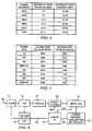
Figure 4 illustrates in tabular format the signal power versus channel bandwidth in the demodulator ofFIG. 1 for both analog and digital carriers. -
Figure 5 illustrates in tabular format accumulator values in the digital AGC ofFIG. 1 for both analog and digital carriers at various symbol rates. -
Figure 6 illustrates exemplary operations according to the present invention for differentiating between analog and digital carriers. -
Figure 7 illustrates a detailed example of an operation ofFIG. 6 . -
Figure 8 diagrammatically illustrates exemplary embodiments of a demodulator of a digital cable communication receiver according to the invention. - Exemplary embodiments of the invention exploit the fact that the
digital AGC 21 ofFIG. 1 monitors and tracks signal level changes after theanalog AGC 15 has locked. For example, given a QAM signal input at 20 into thetuner 11, if theanalog AGC 15 is allowed to free-run and then lock, the accumulator value in thedigital AGC 21 might be, for example, 266k. If the receiver freezes theanalog AGC 15 at this time, and if the signal level at theinput 22 of the A/D converter 13 is attenuated by 20 dB, then the accumulator value in thedigital AGC 21 would change to nearly 510k. This increase in the accumulator value of thedigital AGC 21 reflects the fact that thedigital AGC 21 has tracked the signal attenuation and adjusted the accumulator value appropriately to increase the gain to compensate for signal attenuation. -
Figures 2 and 3 illustrate that the frequency spectrum of a digital carrier is quite different from the frequency spectrum of an analog carrier. More specifically, theFIG. 2 frequency spectrum for a digital carrier (a QAM digital carrier in this example) is flat across a six (6) MHz frequency bandwidth, whereas the frequency spectrum of the analog carrier inFIG. 3 (an NTSC carrier in this example) is not flat, but rather exhibits three (3) distinct spikes corresponding to the video carrier, the audio carrier and the chroma carrier. The signal energy is centered on these three constituent carriers. TheFIG. 3 carrier is US off-the-air channel 28, whose channel center is at 189 MHz, with the video carrier at 187.25 MHz, the audio carrier at 191.75 MHz and the chroma carrier at 190.83 MHz. - Continuing with the
FIG. 3 example of US off-the-air channel 28,FIG. 4 illustrates that the aggregate power of the analog carrier for this channel drops significantly when the channel bandwidth is reduced to 3 MHz. This is because the video carrier frequency and the audio carrier frequency are separated by more than 3 MHz. The aggregate power for the digital QAM carrier ofFIG. 2 , which has a channel center of 450 MHz and a symbol rate of 5.125 Mbaud, also decreases with decreasing bandwidth, but the decrease associated with the digital carrier, for a channel bandwidth change from 4 MHz to 3MHz, is not nearly as significant as the decrease associated with the analog carrier for the same bandwidth change. - Continuing with the same exemplary analog and digital carriers described above,
FIG. 5 illustrates how the accumulator values of thedigital AGC 21 change with the channel bandwidth (shown as the symbol rate inFIG. 5 ), for both the analog and digital carriers. As mentioned above, these accumulator values represent the ability of thedigital AGC 21 to track and compensate for signal level changes after theanalog AGC 15 has locked and then frozen. In general, for the digital carrier, the accumulator value increases as the channel bandwidth increases, whereas the accumulator value for the analog carrier decreases as the channel bandwidth increases. Therefore, analog and digital carriers can be differentiated by observing the accumulator values of thedigital AGC 21 at different channel bandwidths. - As shown in
FIG. 5 , for the analog carrier, the sum, Sum (1:3), of the accumulator values associated with the 1 MHz, 2 MHz and 3 MHz bandwidths (735k) is greater than the corresponding sum, Sum (4:6), for the 4 MHz, 5 MHz and 6 MHz bandwidths (439k). On the other hand, for the digital carrier, the sum of the accumulator values for the three smaller channel bandwidths (768k) is less than the corresponding sum for the three larger channel bandwidths (943k). Therefore, in some exemplary embodiments, the digital AGC accumulator values can be observed at the bandwidths illustrated inFIGS. 4 and 5 , and the accumulator value summations illustrated inFIG. 5 can be used to discriminate between analog and digital carriers. More particularly, if the summation value Sum (1:3) is larger than the summation value Sum (4:6), then the carrier is an analog carrier; otherwise, the carrier is a digital carrier. -
FIG. 6 illustrates exemplary operations for discriminating between analog and digital carriers according to the invention. The analog AGC is allowed to free-run at 61, and it eventually locks at 62. After the analog AGC locks at 62, it is frozen at 63. The channel bandwidth BW is then set at 64, after which information indicative of the signal level (e.g., digital AGC accumulator values) is obtained at 65. As shown at 66, the operations at 64 and 65 can be repeated for as many different channel bandwidths as desired. After collecting the signal level information for all desired channel bandwidths, this collected signal level information is used at 67 to determine whether the carrier is analog or digital. If the carrier is analog, then the receiver moves to the next channel at 69, after which operations can return to 61 where the analog AGC can free-run again. If the carrier is digital, then at 68 the carrier recovery, equalizer and FEC decoder module can execute the conventional scanning algorithm to determine the characteristics of the digital carrier. - As illustrated in
FIG. 6 , an analog carrier can be identified without resort to the scanning algorithm in the carrier recovery, equalizer and FEC decoder module, that is, without exhaustively trying (and ultimately failing) to determine a symbol rate/modulation scheme combination of a digital carrier. -
FIG. 7 illustrates a more detailed example of the operation at 67 inFIG. 6 . At 71, the summation values ofFigure 5 are calculated, and these summation values are compared at 73. If Sum (1:3) is greater than Sum (4:6), then the carrier is identified as analog. Otherwise the carrier is identified as digital. -
FIG. 8 diagrammatically illustrates exemplary embodiments of a demodulator portion of a digital cable communication receiver according to the invention, capable of performing exemplary operations described above relative toFIGS. 5-7 . In particular, acarrier identifier 81 provides a bandwidth control signal (BWc) to the Nyquistfilter 19, thereby to adjustably control the channel bandwidth by adjusting the bandwidth of the Nyquist filter. Thecarrier identifier 81 receives from the accumulator (ACC) of thedigital AGC 21 the accumulator values for each of the respective bandwidths to which the Nyquist filter is set. Based on these accumulator values, thecarrier identifier 81 determines whether the carrier is analog or digital. If the carrier is determined to be digital, then at 83 thecarrier identifier 81 enables the carrier recovery, equalizer andFEC decoder module 23 to perform the conventional scanning algorithm. If the carrier is determined to be analog, then at 85 thecarrier identifier 81 enables theanalog AGC 15 to free-run again. - It will be evident to workers in the art that the exemplary carrier identifier embodiments illustrated in
FIGS. 5-8 can be readily implemented, for example, by suitably modifying software in conventional demodulator arrangements of the type shown generally, for example, inFIG. 1 . Of course, other embodiments may implement the carrier identifier in hardware, or a combination of hardware and software. - Although exemplary embodiments of the invention are described above in detail, this does not limit the scope of the invention, which can be practiced in a variety of embodiments.
Claims (9)
- A method of characterizing a communication signal carrier transmitted on a communication channel in a digital cable communication receiver, comprising:setting a bandwidth of the communication channel to a first plurality of different bandwidth values;for each of the bandwidth values, obtaining information indicative of a corresponding signal level present in the communication channel when set to that bandwidth, the obtained information comprising a first plurality of digital values respectively associated with the first plurality of bandwidth values; andusing the obtained information associated with the first plurality of bandwidth values to determine whether the communication signal carrier is an analogue carrier, said analogue carrier comprising a frequency spectrum with a video carrier spike, an audio carrier spike and a chroma carrier spike, said using step comprising determining a first sum of the digital values,wherein said setting step comprises setting the bandwidth of the communication channel to a second plurality of different bandwidth values which are larger than said first plurality of bandwidth values, wherein said first plurality of bandwidths are selected such that the aggregated power of said analogue carrier in said first bandwidths is substantially reduced as compared to the aggregated power of said analogue carrier in said second plurality of bandwidths, said signal level information comprising a second plurality of digital values respectively associated with said second plurality of bandwidth values, and said using step comprises determining a second sum of said second plurality of digital values and comparing said first sum to said second sum.
- The method of claim 1, wherein said obtaining step comprises obtaining the signal level information from a digital automatic gain control process.
- The method of claim 1 or 2, wherein said using step comprises identifying the communication signal carrier as analogue if said first sum is greater than said second sum.
- The method of claim 1, 2 or 3, wherein said using step comprises identifying the communication signal carrier as digital if said second sum is greater than said first sum.
- The method of any preceding claim, wherein the first plurality of bandwidth values are 1 MHz, 2 MHz, and 3 MHz, and said second plurality of bandwidth values are 4 MHz, 5 MHz and 6 MHz.
- The method of any preceding claim, wherein the communication signal carrier is one of a digital QAM carrier and an analogue NTSC carrier.
- The method of any preceding claim, comprising, before said setting step, free-running an analogue automatic gain control process until the analogue automatic gain control process locks and, also before said setting step, freezing the locked analogue automatic gain control process.
- An apparatus for characterizing a communication signal carrier transmitted on a communication channel in a digital cable communication receiver, comprising:a bandwidth adjuster (81) for setting a bandwidth of the communication channel to a first plurality of different bandwidth values;a signal level monitor (21) coupled to the communication channel for obtaining, for each of the bandwidth values, information indicative of a corresponding signal level present in the communication channel when set to that bandwidth, the obtained information comprising a first plurality of digital values respectively associated with the first plurality of bandwidth values; anda carrier identifier (81) coupled to said signal level monitor for using the obtained information associated with the plurality of bandwidth values to determine whether the communications signal carrier is an analogue carrier, said analogue carrier comprising a frequency spectrum with a video carrier spike, an audio carrier spike and a chroma carrier spike, said carrier identifier being for determining a first sum of the digital values,wherein said bandwidth adjuster is for setting the bandwidth of the communication channel to a second plurality of different bandwidth values which are larger than said first plurality of bandwidth values, wherein said first plurality of bandwidths are selected such that the aggregated power of said analogue carrier in said first plurality of bandwidths is substantially reduced as compared to the aggregated power of said analogue carrier in said second plurality of bandwidths said signal level information comprises a second plurality of digital values respectively associated with said second plurality of bandwidth values, and said carrier identifier is for determining a second sum of said second digital values, and for comparing said first sum to said second sum.
- The apparatus of claim 8, wherein said signal level monitor is provided as part of a digital automatic gain controller which is arranged to produce the said plurality of digital values.
Applications Claiming Priority (1)
| Application Number | Priority Date | Filing Date | Title |
|---|---|---|---|
| US10/882,690 US7929649B2 (en) | 2004-06-30 | 2004-06-30 | Analog/digital carrier differentiation in digital cable receivers |
Publications (2)
| Publication Number | Publication Date |
|---|---|
| EP1613058A1 EP1613058A1 (en) | 2006-01-04 |
| EP1613058B1 true EP1613058B1 (en) | 2011-09-21 |
Family
ID=35134191
Family Applications (1)
| Application Number | Title | Priority Date | Filing Date |
|---|---|---|---|
| EP05254100A Expired - Lifetime EP1613058B1 (en) | 2004-06-30 | 2005-06-29 | Analog/digital carrier differentiation in digital cable receivers |
Country Status (2)
| Country | Link |
|---|---|
| US (1) | US7929649B2 (en) |
| EP (1) | EP1613058B1 (en) |
Families Citing this family (14)
| Publication number | Priority date | Publication date | Assignee | Title |
|---|---|---|---|---|
| WO2006079990A1 (en) * | 2005-01-28 | 2006-08-03 | Nxp B.V. | Intermediate frequency processing device for processing both analogue and digital television intermediate frequency signals |
| ITMI20071565A1 (en) * | 2007-07-31 | 2009-02-01 | Ro Ve R Lab S P A | PROCESS FOR THE ANALYSIS OF AN ANALOGUE AND DIGITAL TV SIGNAL AND ITS APPARATUS |
| US8139614B2 (en) * | 2008-06-06 | 2012-03-20 | Maxim Integrated Products, Inc. | Robust narrowband symbol and frame synchronizer for power-line communication |
| US8165172B2 (en) * | 2008-06-06 | 2012-04-24 | Maxim Integrated Products, Inc. | Robust wideband symbol and frame synchronizer for power-line communication |
| US8315341B2 (en) | 2008-06-06 | 2012-11-20 | Maxim Integrated Products, Inc. | Soft repetition code combiner using channel state information |
| US8315152B2 (en) | 2008-06-06 | 2012-11-20 | Maxim Integrated Products, Inc. | System and method for applying multi-tone OFDM based communications within a prescribed frequency range |
| US8276025B2 (en) * | 2008-06-06 | 2012-09-25 | Maxim Integrated Products, Inc. | Block interleaving scheme with configurable size to achieve time and frequency diversity |
| US8284825B2 (en) * | 2008-06-06 | 2012-10-09 | Maxim Integrated Products, Inc. | Blind channel quality estimator |
| US8149967B2 (en) * | 2008-06-06 | 2012-04-03 | Maxim Integrated Products, Inc. | Combined dual feed-forward and feedback analog and digital automatic gain control for broadband communication |
| US8472576B2 (en) | 2008-06-06 | 2013-06-25 | Maxim Integrated Products, Inc. | Jammer canceller for power-line communication |
| US8320233B2 (en) * | 2009-06-12 | 2012-11-27 | Maxim Integrated Products, Inc. | Transmitter and method for applying multi-tone OFDM based communications within a lower frequency range |
| WO2011100920A2 (en) * | 2011-04-13 | 2011-08-25 | 华为技术有限公司 | Method and device for automatic gain adjustment in wireless receiver |
| CN106847694B (en) * | 2015-12-03 | 2019-09-27 | 中芯国际集成电路制造(上海)有限公司 | Method of forming a semiconductor device |
| CN114172764B (en) * | 2021-12-03 | 2023-09-22 | 上海橙科微电子科技有限公司 | Method and system for detecting different rates in data communication |
Family Cites Families (11)
| Publication number | Priority date | Publication date | Assignee | Title |
|---|---|---|---|---|
| FR2552282B1 (en) * | 1983-09-21 | 1990-07-13 | Veillard Jacques | METHOD AND DEVICE FOR CONSISTENT DEMODULATION OF DIGITALLY MODULATED CARRIER |
| US6333767B1 (en) * | 1996-12-26 | 2001-12-25 | Samsung Electronics Co., Ltd. | Radio receivers for receiving both VSB and QAM digital television signals with carriers offset by 2.69 MHz |
| US6725463B1 (en) * | 1997-08-01 | 2004-04-20 | Microtune (Texas), L.P. | Dual mode tuner for co-existing digital and analog television signals |
| US6483553B1 (en) * | 1998-05-15 | 2002-11-19 | Lg Electronics Inc. | TV receiver for digital/analog combined use |
| US6100835A (en) * | 1998-09-10 | 2000-08-08 | Spacecode Llc | Multi-symbol analysis for digital symbol determination |
| US6668027B1 (en) * | 1999-03-02 | 2003-12-23 | Hitachi America, Ltd. | Self adjusting automatic gain control (AGC) power reference level circuit |
| US6369857B1 (en) * | 1999-05-13 | 2002-04-09 | Sarnoff Corporation | Receiver for analog and digital television signals |
| JP3540242B2 (en) * | 2000-03-30 | 2004-07-07 | 松下電器産業株式会社 | Multi-system receiver |
| JP2002369087A (en) * | 2001-06-06 | 2002-12-20 | Funai Electric Co Ltd | Digital/analog broadcasting receiver |
| GB0221296D0 (en) * | 2002-09-13 | 2002-10-23 | British Broadcasting Corp | Improved digital broadcast receiver |
| TWI220611B (en) * | 2002-10-04 | 2004-08-21 | Realtek Semiconductor Corp | Channel estimation device of Ethernet network and method thereof |
-
2004
- 2004-06-30 US US10/882,690 patent/US7929649B2/en not_active Expired - Fee Related
-
2005
- 2005-06-29 EP EP05254100A patent/EP1613058B1/en not_active Expired - Lifetime
Also Published As
| Publication number | Publication date |
|---|---|
| US7929649B2 (en) | 2011-04-19 |
| US20060002494A1 (en) | 2006-01-05 |
| EP1613058A1 (en) | 2006-01-04 |
Similar Documents
| Publication | Publication Date | Title |
|---|---|---|
| US7929649B2 (en) | Analog/digital carrier differentiation in digital cable receivers | |
| US7177615B2 (en) | Receiver with adjacent interfering wave elimination function | |
| CN1110175C (en) | Automatic gain control circuit and method for digital television receiver | |
| EP0064819B1 (en) | An fm signal demodulation system | |
| DE69320868T2 (en) | Receiver with a combined AM-FM demodulator | |
| DE69520549T2 (en) | System for processing a digital video signal with a notch filter to eliminate interference between the same transmission channels | |
| AU740454B2 (en) | Method and apparatus for receiving a plurality of signals having different frequency bandwidths | |
| EP0079825B1 (en) | Improved selectivity means in amplitude modulated radio receivers | |
| US6445425B1 (en) | Automatic fine tuning of receiver for digital television signals | |
| KR20050032595A (en) | Method and apparatus for performing channel detection | |
| US6046781A (en) | Automatic fine tuning of TV receiver for receiving both digital and analog TV signals | |
| US8649463B2 (en) | Radio communication apparatus | |
| CN101147393A (en) | Non-linear signal distortion detection using multiple signal to noise ratio measurement sources | |
| EP2430808A1 (en) | Robust sensing of dvb-t/h transmissions in the presence of frequency offsets | |
| CN100361511C (en) | NTSC signal detector | |
| JP2002112130A (en) | Broadcast signal receiver tuning system and method | |
| US7567298B2 (en) | Apparatus and method for detecting NTSC co-channel interference | |
| WO2008077274A1 (en) | Method and device for automatic gain control | |
| EP2171842B1 (en) | Amplifier automatic gain control circuit for QAM modulated and continuous wave signals | |
| EP1751969B1 (en) | Apparatus and method for compensating for varying adjacent channel conditions | |
| JP2003516048A (en) | Tuner alignment | |
| MXPA02000555A (en) | Selective gain adjustement to aid carrier acquisition in a high definition television receiver. | |
| CN116614146A (en) | Power line communication narrowband interference detection and suppression device, method and chip | |
| CN101390386B (en) | Voice signal processing circuit | |
| KR100526899B1 (en) | Method for reducing downstream noise in cable modem |
Legal Events
| Date | Code | Title | Description |
|---|---|---|---|
| PUAI | Public reference made under article 153(3) epc to a published international application that has entered the european phase |
Free format text: ORIGINAL CODE: 0009012 |
|
| AK | Designated contracting states |
Kind code of ref document: A1 Designated state(s): AT BE BG CH CY CZ DE DK EE ES FI FR GB GR HU IE IS IT LI LT LU MC NL PL PT RO SE SI SK TR |
|
| AX | Request for extension of the european patent |
Extension state: AL BA HR LV MK YU |
|
| 17P | Request for examination filed |
Effective date: 20060630 |
|
| AKX | Designation fees paid |
Designated state(s): DE FR GB IT |
|
| 17Q | First examination report despatched |
Effective date: 20080709 |
|
| GRAP | Despatch of communication of intention to grant a patent |
Free format text: ORIGINAL CODE: EPIDOSNIGR1 |
|
| GRAS | Grant fee paid |
Free format text: ORIGINAL CODE: EPIDOSNIGR3 |
|
| GRAA | (expected) grant |
Free format text: ORIGINAL CODE: 0009210 |
|
| AK | Designated contracting states |
Kind code of ref document: B1 Designated state(s): DE FR GB IT |
|
| REG | Reference to a national code |
Ref country code: GB Ref legal event code: FG4D |
|
| REG | Reference to a national code |
Ref country code: DE Ref legal event code: R096 Ref document number: 602005030113 Country of ref document: DE Effective date: 20111124 |
|
| PG25 | Lapsed in a contracting state [announced via postgrant information from national office to epo] |
Ref country code: IT Free format text: LAPSE BECAUSE OF FAILURE TO SUBMIT A TRANSLATION OF THE DESCRIPTION OR TO PAY THE FEE WITHIN THE PRESCRIBED TIME-LIMIT Effective date: 20110921 |
|
| PLBE | No opposition filed within time limit |
Free format text: ORIGINAL CODE: 0009261 |
|
| STAA | Information on the status of an ep patent application or granted ep patent |
Free format text: STATUS: NO OPPOSITION FILED WITHIN TIME LIMIT |
|
| 26N | No opposition filed |
Effective date: 20120622 |
|
| REG | Reference to a national code |
Ref country code: DE Ref legal event code: R097 Ref document number: 602005030113 Country of ref document: DE Effective date: 20120622 |
|
| REG | Reference to a national code |
Ref country code: DE Ref legal event code: R119 Ref document number: 602005030113 Country of ref document: DE Effective date: 20130101 |
|
| PG25 | Lapsed in a contracting state [announced via postgrant information from national office to epo] |
Ref country code: DE Free format text: LAPSE BECAUSE OF NON-PAYMENT OF DUE FEES Effective date: 20130101 |
|
| REG | Reference to a national code |
Ref country code: FR Ref legal event code: PLFP Year of fee payment: 12 |
|
| REG | Reference to a national code |
Ref country code: FR Ref legal event code: PLFP Year of fee payment: 13 |
|
| REG | Reference to a national code |
Ref country code: FR Ref legal event code: PLFP Year of fee payment: 14 |
|
| PGFP | Annual fee paid to national office [announced via postgrant information from national office to epo] |
Ref country code: FR Payment date: 20190522 Year of fee payment: 15 |
|
| PGFP | Annual fee paid to national office [announced via postgrant information from national office to epo] |
Ref country code: GB Payment date: 20190522 Year of fee payment: 15 |
|
| GBPC | Gb: european patent ceased through non-payment of renewal fee |
Effective date: 20200629 |
|
| PG25 | Lapsed in a contracting state [announced via postgrant information from national office to epo] |
Ref country code: GB Free format text: LAPSE BECAUSE OF NON-PAYMENT OF DUE FEES Effective date: 20200629 Ref country code: FR Free format text: LAPSE BECAUSE OF NON-PAYMENT OF DUE FEES Effective date: 20200630 |