EP1612947A2 - Method to adaptive scale the input to a channel decoder - Google Patents
Method to adaptive scale the input to a channel decoder Download PDFInfo
- Publication number
- EP1612947A2 EP1612947A2 EP05254081A EP05254081A EP1612947A2 EP 1612947 A2 EP1612947 A2 EP 1612947A2 EP 05254081 A EP05254081 A EP 05254081A EP 05254081 A EP05254081 A EP 05254081A EP 1612947 A2 EP1612947 A2 EP 1612947A2
- Authority
- EP
- European Patent Office
- Prior art keywords
- bits
- adaptive
- bit
- average
- computing
- Prior art date
- Legal status (The legal status is an assumption and is not a legal conclusion. Google has not performed a legal analysis and makes no representation as to the accuracy of the status listed.)
- Granted
Links
- 230000003044 adaptive effect Effects 0.000 title claims description 46
- 238000000034 method Methods 0.000 title claims description 10
- 238000004891 communication Methods 0.000 claims description 25
- 230000004044 response Effects 0.000 claims description 7
- 238000001914 filtration Methods 0.000 claims 2
- 230000000593 degrading effect Effects 0.000 abstract description 2
- 238000005562 fading Methods 0.000 description 8
- 238000010586 diagram Methods 0.000 description 6
- 230000005540 biological transmission Effects 0.000 description 5
- 230000000052 comparative effect Effects 0.000 description 4
- 230000001419 dependent effect Effects 0.000 description 3
- 238000012545 processing Methods 0.000 description 3
- 238000004088 simulation Methods 0.000 description 3
- 230000000694 effects Effects 0.000 description 2
- 230000006872 improvement Effects 0.000 description 2
- 239000000654 additive Substances 0.000 description 1
- 230000000996 additive effect Effects 0.000 description 1
- 230000004075 alteration Effects 0.000 description 1
- 230000003321 amplification Effects 0.000 description 1
- 238000013459 approach Methods 0.000 description 1
- 238000010276 construction Methods 0.000 description 1
- 238000012937 correction Methods 0.000 description 1
- 230000008878 coupling Effects 0.000 description 1
- 238000010168 coupling process Methods 0.000 description 1
- 238000005859 coupling reaction Methods 0.000 description 1
- 230000007423 decrease Effects 0.000 description 1
- 230000007812 deficiency Effects 0.000 description 1
- 230000007774 longterm Effects 0.000 description 1
- 238000010295 mobile communication Methods 0.000 description 1
- 238000003199 nucleic acid amplification method Methods 0.000 description 1
- 230000008569 process Effects 0.000 description 1
- 238000001228 spectrum Methods 0.000 description 1
- 238000006467 substitution reaction Methods 0.000 description 1
Images

Classifications
-
- H—ELECTRICITY
- H03—ELECTRONIC CIRCUITRY
- H03M—CODING; DECODING; CODE CONVERSION IN GENERAL
- H03M13/00—Coding, decoding or code conversion, for error detection or error correction; Coding theory basic assumptions; Coding bounds; Error probability evaluation methods; Channel models; Simulation or testing of codes
- H03M13/37—Decoding methods or techniques, not specific to the particular type of coding provided for in groups H03M13/03 - H03M13/35
-
- H—ELECTRICITY
- H03—ELECTRONIC CIRCUITRY
- H03M—CODING; DECODING; CODE CONVERSION IN GENERAL
- H03M13/00—Coding, decoding or code conversion, for error detection or error correction; Coding theory basic assumptions; Coding bounds; Error probability evaluation methods; Channel models; Simulation or testing of codes
- H03M13/65—Purpose and implementation aspects
- H03M13/6577—Representation or format of variables, register sizes or word-lengths and quantization
-
- H—ELECTRICITY
- H03—ELECTRONIC CIRCUITRY
- H03M—CODING; DECODING; CODE CONVERSION IN GENERAL
- H03M13/00—Coding, decoding or code conversion, for error detection or error correction; Coding theory basic assumptions; Coding bounds; Error probability evaluation methods; Channel models; Simulation or testing of codes
- H03M13/65—Purpose and implementation aspects
- H03M13/6577—Representation or format of variables, register sizes or word-lengths and quantization
- H03M13/658—Scaling by multiplication or division
-
- H—ELECTRICITY
- H03—ELECTRONIC CIRCUITRY
- H03M—CODING; DECODING; CODE CONVERSION IN GENERAL
- H03M13/00—Coding, decoding or code conversion, for error detection or error correction; Coding theory basic assumptions; Coding bounds; Error probability evaluation methods; Channel models; Simulation or testing of codes
- H03M13/65—Purpose and implementation aspects
- H03M13/6577—Representation or format of variables, register sizes or word-lengths and quantization
- H03M13/6591—Truncation, saturation and clamping
-
- H—ELECTRICITY
- H04—ELECTRIC COMMUNICATION TECHNIQUE
- H04L—TRANSMISSION OF DIGITAL INFORMATION, e.g. TELEGRAPHIC COMMUNICATION
- H04L1/00—Arrangements for detecting or preventing errors in the information received
- H04L1/004—Arrangements for detecting or preventing errors in the information received by using forward error control
- H04L1/0045—Arrangements at the receiver end
-
- H—ELECTRICITY
- H03—ELECTRONIC CIRCUITRY
- H03M—CODING; DECODING; CODE CONVERSION IN GENERAL
- H03M13/00—Coding, decoding or code conversion, for error detection or error correction; Coding theory basic assumptions; Coding bounds; Error probability evaluation methods; Channel models; Simulation or testing of codes
- H03M13/29—Coding, decoding or code conversion, for error detection or error correction; Coding theory basic assumptions; Coding bounds; Error probability evaluation methods; Channel models; Simulation or testing of codes combining two or more codes or code structures, e.g. product codes, generalised product codes, concatenated codes, inner and outer codes
- H03M13/2957—Turbo codes and decoding
-
- H—ELECTRICITY
- H03—ELECTRONIC CIRCUITRY
- H03M—CODING; DECODING; CODE CONVERSION IN GENERAL
- H03M13/00—Coding, decoding or code conversion, for error detection or error correction; Coding theory basic assumptions; Coding bounds; Error probability evaluation methods; Channel models; Simulation or testing of codes
- H03M13/37—Decoding methods or techniques, not specific to the particular type of coding provided for in groups H03M13/03 - H03M13/35
- H03M13/45—Soft decoding, i.e. using symbol reliability information
Definitions
- the present invention is directed, in general, to processing inputs for channel decoders in wireless communication systems and, more specifically, to avoiding loss of performance during channel decoding in code division multiple access systems.
- First generation analog-based mobile telecommunication systems generally use a pair of dedicated radio channels with typically 30 kilo-Hertz (kHz) bandwidth to establish connection between the base station (BS) and mobile station (MS).
- Second generation, digital wireless telecommunication systems such as those conforming to the Global System for Mobile Communication (GSM) or Interim Standard 136 (IS-136), employ a time division multiple access (TDMA) approach in which each pair of dedicated radio channels convey a number of connections between the mobile station(s) and the base station, with each mobile station being allocated a timeslot on the channel.
- GSM Global System for Mobile Communication
- IS-136 Interim Standard 136
- TDMA time division multiple access
- each pair of dedicated radio channels convey a number of connections between the mobile station(s) and the base station, with each mobile station being allocated a timeslot on the channel.
- the radio channel bandwidth is larger---for example, 200 kHz for GSM systems.
- CDMA Code division multiple access
- IS-95 Interim Standard 95
- UMTS Universal Mobile Telecommunication System
- UTRA FDD Universal Mobile Telecommunication System
- CDMA Code division multiple access
- UMTS Universal Mobile Telecommunication System
- UTRA FDD Universal Mobile Telecommunication System
- Each band conveys communications for multiple users, with each user assigned a pseudo-noise (PN) random sequence constructed from channelization and scrambling codes by which information is modulated as "symbols" onto the channel.
- PN pseudo-noise
- a typical wireless system includes a transmitter where information bits are encoded by a channel encoder and modulated by a modulator for transmission through a wireless communication channel having fading and additive white Gaussian noise (AWGN).
- a typical wireless receiver operating on wireless signals received from the channel includes an inner modem, such as a rake receiver in a UMTS Frequency Division Duplex (FDD) system, and a channel decoder to correct errors introduced by the channel.
- FDD Frequency Division Duplex
- the receiver performance depends, to a large extent, on the performance of the channel decoder.
- a channel decoder working with a soft decision has approximately 3 decibels (dB) gain over a channel decoder working over hard decision input. However, that 3 dB gain can be lost without proper input of the received wireless signal to the channel decoder.
- a primary object of the present invention to provide, for use in a wireless communication system, determination of a range R of effective bits (those containing information) within the N output bits from an inner modem for use in selecting the M soft bits to pass to a channel decoder, thereby avoiding underflow or overflow degrading the channel decoder performance.
- the average and standard deviation of 1P outputs are used to determine the range R of effective bits, with the N bits shifted and clipped based on the computed value of R so that the M most significant bits from that range R are passed to the channel decoder.
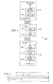
- FIGURE 1 is a high level diagram of a wireless communication system implementing adaptive scaling of the input to a channel decoder according to one embodiment of the present invention
- FIGURES 2A and 2B are comparative diagrams of, respectively, constant (or fixed) signal bit selection for scaling between the inner modem output and the channel decoder input and adaptive bit selection for scaling according to one embodiment of the present invention
- FIGURE 3 diagramatically illustrates adaptive scaling of inner modem output for input to a channel decoder according to one embodiment of the present invention
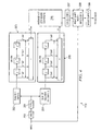
- FIGURE 4 is a block diagram for an adaptive scaler in accordance with one embodiment of the present invention.
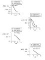
- FIGURES 5A through 5D depict comparative simulation plots for constant scaling versus adaptive scaling according to one embodiment of the present invention.
- FIGURES 1 through 5D discussed below, and the various embodiments used to describe the principles of the present invention in this patent document are by way of illustration only and should not be construed in any way to limit the scope of the invention. Those skilled in the art will understand that the principles of the present invention may be implemented in any suitably arranged device.
- FIGURE 1 is a high level diagram of a wireless communication system implementing adaptive scaling of the input to a channel decoder according to one embodiment of the present invention.
- Wireless communication system 100 includes a transmitter 101 transmitting symbols containing encoded information bits on a wireless communication channel 102 coupling transmitter 101 to a receiver 103.
- Transmitter 101 receives information bits from an internal or external data processing circuit (not shown) at a channel encoder 104.
- the encoded information bits produced by channel encoder 104 are passed to a modulation unit 105, which generates symbols and transmits those symbols over wireless communication channel 102.
- the transmitted symbols are potentially subjected to at least fading and AWGN effects 106-107, such that the symbols received at receiver 103 may contain errors requiring correction.
- an inner modem 108 demodulates the received symbols for decoding by a channel decoder 109.
- the output bits produced by channel decoder 109 are passed to an internal or external data processing circuit (not shown).
- the present invention includes an adaptive scaler 110 within the receiver 103 between inner modem 108 and channel decoder 109, as described in further detail below.
- wireless communication system 101 is a UMTS FDD system.
- CDMA systems make use of the PN code that has a much higher bit rate than the symbol rate of the information bit sequence being encoded for transmission.
- the information bit sequence is passed through a filter with a root-raised cosine frequency characteristic, with the resulting filtered signal presented to a radio frequency (RF) system for modulation onto an RF carrier.
- RF radio frequency
- the received signal is demodulated at the inner modem 108 by the conjugate PN sequence to produce bit output, typically using a rake finger with the output of many rake fingers combined by a rake combiner, with the rake fingers and rake combiner constituting a rake receiver normally used in UMTS FDD systems.
- the output from the rake receiver is passed on to the channel decoder 109, which may be a Viterbi/Turbo decoder.
- the dynamic range of the output from inner modem 108 varies as a result of several factors: The inner modem 108 demodulates a particular physical channel, and the output is therefore dependent on the relationship of the physical channel power to the total received power.
- the dynamic range of the output from inner modem 108 is affected by the amount of amplification used by the receiver 103 based on Automatic Gain Control (AGC).
- AGC Automatic Gain Control
- the output from inner modem 108 is dependent on the number of fingers used to produce the output from the rake combiner, and the strengths of the multipath interferences associated with those fingers. Fading has a high impact on variation of the output from the inner modem 108, being the primary reason for rapid dynamic range fluctuations within short time intervals. Shadowing is a long term fading process where the signal varies due to topographical variation.
- power control has an impact on the received signal strength and the inner model output.
- the transmitted symbols pass through channel 102, which introduce noise and distort the signal.
- the channel encoder 104 introduces additional information to the information bits being encoded and modulated and also randomizes the order of the information within the transmitted symbol stream.
- the additional information allows algorithms, such as the Viterbi algorithm, to recover the original bit sequence even though errors might exist within the received sequence. Randomization of the information protects against channel fading, which introduces burst errors into the received symbol stream.
- Channel decoders typically give optimal performance for eight bit input data as shown in TABLE I, which illustrates the number of soft bits for optimal performance for AWGN and fading channel effects, with increase in the bitwidth above eight bits not producing appreciable improvement in system performance.
- TABLE I AWGN Fading Viterbi decoder 4 bits 8 bits Turbo decoder 6 bits 8 bits
- the output bitwidth of inner modem 108 is usually greater than eight bits, and thus should be scaled before being input to channel decoder 109. Since the output of inner modem 108 varies as described above, the output must be scaled such that the entire bitwidth of the channel decoder 109 (i.e., eight bits) is properly utilized. Too much scaling results in loss of performance due to underflow caused by loss of vital decoding information (since small values are truncated to zero), and failure to completely utilize decoder bitwidth. Too little scaling induces loss of performance due to saturation in the decoder, where all input values are clipped due to overflow. Accordingly, scaling of the input to the channel decoder 109 should be performed such that the decoder input utilizes the complete 8-bit bitwidth while avoiding underflow/overflow situations.
- the output of inner modem 108 should be scaled to eight soft bits before being passed to the channel decoder 109. For instance, if sixteen bits are allocated for the output of the inner modem 108 and eight bits are allocated for the input of channel decoder 109, eight bits need to be appropriately selected by scaling the 16-bit inner modem output.
- FIGURES 2A and 2B are comparative diagrams of, respectively, constant (or fixed) signal bit selection for scaling between the inner modem output and the channel decoder input and adaptive bit selection for scaling according to one embodiment of the present invention. Since the dynamic range of the output from the inner modem varies, constant bit selection for scaling as illustrated in FIGURE 2A, in which the eight most significant bits (MSBs) of the output from inner modem 108 are selected as an example, will affect the decoder performance.
- MSBs most significant bits
- FIGURE 2B illustrates adaptive bit selection from the output from inner modem 108 for use by the input of channel decoder 109, in which the set of bits selected for scaling match the instantaneous dynamic range of the inner modem output.
- the adaptive bit selection for scaling ensures that decoder bitwidth is properly utilized even when the modem output varies, providing optimal decoder performance under varying modem output conditions.
- FIGURE 3 diagramatically illustrates adaptive scaling of inner modem output for input to a channel decoder according to one embodiment of the present invention.
- the inner modem 108 has N dedicated output bits, while the channel decoder 109 has M dedicated input bits and R is the number of effective bits--that is, the number of bits that contain information--within the output from the inner modem 108. With constant scaling, choosing the M most significant bits M c results in underflow and small values are passed to the decoder.
- the input to the inner modem 108 is the sum of all users' data and many physical channels, while the output of inner modem 108 is only one physical channel for a particular user. Consequently the power of the output is much less than the total power of the input, and although N bits are allocated for the inner modem output, choosing the most significant M bits as the input to the channel decoder 109 results in performance loss as described above.
- Adaptive scaler 110 measures tracks the variation of the inner modem output range R and passes the appropriate M bits (i.e., the M most significant bit from the set of R bits) to the channel decoder 109, resulting in minimal loss of data.
- FIGURE 4 is a block diagram for an adaptive scaler in accordance with one embodiment of the present invention.
- Adaptive scaler 110 dynamically detects the range R of the input data and scales the input data accordingly.
- the input to the adaptive scaler 110 is the N bit output of inner modem 108, and adaptive scaler 110 generates M soft bits to the channel decoder 109.
- Adaptive scaler 110 includes an input for receiving the N bit output of inner modem 108 at an absolute value computation unit 200.
- a log 2 operation is performed by unit 201 on the absolute value of the input as part of identifying the effective bits R to be used as the input to the channel decoder 109, where the range R is dependent on the strength of the particular signal being demodulated by the inner modem 108 and changes with time.
- the log 2 operation drastically reduces computational complexity.
- Adaptive scaler 110 estimates the variation in effective bits R by calculating the average and standard deviation of the log 2 values from unit 201, which may then be used to scale the input to the channel decoder 109 to the M required soft bits. After taking the absolute value and performing the log 2 operation, the outputs from unit 201 are arranged into blocks of lvalues, from which the sum of these values is calculated by summing unit 202.
- the moving-average finite impulse response (MA-FIR) filter 203 calculates the sum of P outputs from unit 202, which is equivalent to the sum of the previous 1P values at the outputs of the unit 201. The sum of the squares of l values for the output of unit 201 is calculated by summing unit 204.
- the MA-FIR filter 205 calculates the sum of P outputs from unit 204, which is equivalent to the sum of squares from the previous 1P values for the output of unit 201.
- Each filter 203 and 205 has P taps updated once every l inputs to calculate the sum or sum of the squares, respectively, of the outputs from unit 201.
- FIGURES 5A through 5D depict comparative simulation plots for constant scaling versus adaptive scaling according to one embodiment of the present invention.
- DCCH CDMA Data Control Channel
- DTCH Data Transport Channel
- the transmission modeled employed is case 1 from UE Radio Transmission and Reception (FDD), 3GPP TS25.101 v.4.0.0.2.
- the inner modem input included 10 bits: seven bits to quantize the fractional portion, two bits for the integer, and one bit for the sign.
- FIGURES 5A and 5B depict the block error rate (BLER) versus signal-to-noise ratio (SNR) for adaptive and conventional (constant) scaling under AWGN channel conditions for DTCH and DCCH, respectively.
- BLER block error rate
- SNR signal-to-noise ratio
- FIGURES 5C and 5D depict BLER versus SNR for adaptive and conventional scaling under fading conditions in which the velocity of the mobile is 240 kilometers/hour (Km/h), with the fading taps normalized to unity, for DTCH and DCCH, respectively.
- conventional scaling yields poor results attributable to very low values being passed to the channel decoder, which may be improved using adaptive scaling.
- the present invention utilizes adaptive scaling to scale the inner modem output in CDMA systems to pass M soft bits as input to the channel decoder without significant loss of performance despite variation in inner modem output range.
- Data bits in a digital communication system are encoded using channel coding (e.g., convolutional or turbo) at the transmission side and decoded using channel decoding (e.g., Viterbi or turbo) at the receiving side.
- channel coding e.g., convolutional or turbo
- channel decoding e.g., Viterbi or turbo
- Viterbi and turbo decoders give optimal performance with a 4-8 bit soft decision
- the input to the channel decoder should be adaptively matched to 4-8 bits to avoid loss of performance.
- Adaptive scaling provides such matching.
- the present invention may be used between the output of an inner modem (e.g., Rake fingers) and the input to a channel decoder (Viterbi or turbo) in a CDMA-based system such as FDD mode Wideband CDMA (WCDMA).
- an inner modem e.g., Rake fingers
- a channel decoder Viterbi or turbo
- WCDMA Wideband CDMA
Landscapes
- Engineering & Computer Science (AREA)
- Physics & Mathematics (AREA)
- Probability & Statistics with Applications (AREA)
- Theoretical Computer Science (AREA)
- Computer Networks & Wireless Communication (AREA)
- Signal Processing (AREA)
- Digital Transmission Methods That Use Modulated Carrier Waves (AREA)
- Compression, Expansion, Code Conversion, And Decoders (AREA)
- Transmission Systems Not Characterized By The Medium Used For Transmission (AREA)
Abstract
Description
- The present invention is directed, in general, to processing inputs for channel decoders in wireless communication systems and, more specifically, to avoiding loss of performance during channel decoding in code division multiple access systems.
- First generation analog-based mobile telecommunication systems generally use a pair of dedicated radio channels with typically 30 kilo-Hertz (kHz) bandwidth to establish connection between the base station (BS) and mobile station (MS). Second generation, digital wireless telecommunication systems such as those conforming to the Global System for Mobile Communication (GSM) or Interim Standard 136 (IS-136), employ a time division multiple access (TDMA) approach in which each pair of dedicated radio channels convey a number of connections between the mobile station(s) and the base station, with each mobile station being allocated a timeslot on the channel. In those systems, the radio channel bandwidth is larger---for example, 200 kHz for GSM systems.
- Code division multiple access (CDMA), used in Interim Standard 95 (IS-95) or Universal Mobile Telecommunication System (UMTS) Terrestrial Radio Access Frequency Division Duplex (UTRA FDD) mobile telecommunication systems, are spread spectrum systems employing a pair of radio channels with much larger bandwidth than either first or second generation systems-that is, 1.5 mega-Hertz (MHz) for IS-95 and 5.0 MHz for UTRA FDD. Each band conveys communications for multiple users, with each user assigned a pseudo-noise (PN) random sequence constructed from channelization and scrambling codes by which information is modulated as "symbols" onto the channel. A receiver having knowledge of the PN code for a particular user is able to distinguish that user from the others.
- A typical wireless system includes a transmitter where information bits are encoded by a channel encoder and modulated by a modulator for transmission through a wireless communication channel having fading and additive white Gaussian noise (AWGN). A typical wireless receiver operating on wireless signals received from the channel includes an inner modem, such as a rake receiver in a UMTS Frequency Division Duplex (FDD) system, and a channel decoder to correct errors introduced by the channel. The receiver performance depends, to a large extent, on the performance of the channel decoder. A channel decoder working with a soft decision has approximately 3 decibels (dB) gain over a channel decoder working over hard decision input. However, that 3 dB gain can be lost without proper input of the received wireless signal to the channel decoder.
- There is, therefore, a need in the art for a method of ensuring receiver performance in a wireless communication system.
- To address the above-discussed deficiencies of the prior art, it is a primary object of the present invention to provide, for use in a wireless communication system, determination of a range R of effective bits (those containing information) within the N output bits from an inner modem for use in selecting the M soft bits to pass to a channel decoder, thereby avoiding underflow or overflow degrading the channel decoder performance. The average and standard deviation of 1P outputs are used to determine the range R of effective bits, with the N bits shifted and clipped based on the computed value of R so that the M most significant bits from that range R are passed to the channel decoder.
- The foregoing has outlined rather broadly the features and technical advantages of the present invention so that those skilled in the art may better understand the detailed description of the invention that follows. Additional features and advantages of the invention will be described hereinafter that form the subject of the claims of the invention. Those skilled in the art will appreciate that they may readily use the conception and the specific embodiment disclosed as a basis for modifying or designing other structures for carrying out the same purposes of the present invention. Those skilled in the art will also realize that such equivalent constructions do not depart from the spirit and scope of the invention in its broadest form.
- Before undertaking the DETAILED DESCRIPTION OF THE INVENTION below, it may be advantageous to set forth definitions of certain words or phrases used throughout this patent document: the terms "include" and "comprise," as well as derivatives thereof, mean inclusion without limitation; the term "or" is inclusive, meaning and/or; the phrases "associated with" and "associated therewith," as well as derivatives thereof, may mean to include, be included within, interconnect with, contain, be contained within, connect to or with, couple to or with, be communicable with, cooperate with, interleave, juxtapose, be proximate to, be bound to or with, have, have a property of, or the like; and the term "controller" means any device, system or part thereof that controls at least one operation, whether such a device is implemented in hardware, firmware, software or some combination of at least two of the same. It should be noted that the functionality associated with any particular controller may be centralized or distributed, whether locally or remotely. Definitions for certain words and phrases are provided throughout this patent document, and those of ordinary skill in the art will understand that such definitions apply in many, if not most, instances to prior as well as future uses of such defined words and phrases.
- For a more complete understanding of the present invention, and the advantages thereof, reference is now made to the following descriptions taken in conjunction with the accompanying drawings, wherein like numbers designate like objects, and in which:
- FIGURE 1 is a high level diagram of a wireless communication system implementing adaptive scaling of the input to a channel decoder according to one embodiment of the present invention;
- FIGURES 2A and 2B are comparative diagrams of, respectively, constant (or fixed) signal bit selection for scaling between the inner modem output and the channel decoder input and adaptive bit selection for scaling according to one embodiment of the present invention;
- FIGURE 3 diagramatically illustrates adaptive scaling of inner modem output for input to a channel decoder according to one embodiment of the present invention;
- FIGURE 4 is a block diagram for an adaptive scaler in accordance with one embodiment of the present invention; and
- FIGURES 5A through 5D depict comparative simulation plots for constant scaling versus adaptive scaling according to one embodiment of the present invention.
- FIGURES 1 through 5D, discussed below, and the various embodiments used to describe the principles of the present invention in this patent document are by way of illustration only and should not be construed in any way to limit the scope of the invention. Those skilled in the art will understand that the principles of the present invention may be implemented in any suitably arranged device.
- FIGURE 1 is a high level diagram of a wireless communication system implementing adaptive scaling of the input to a channel decoder according to one embodiment of the present invention.
Wireless communication system 100 includes atransmitter 101 transmitting symbols containing encoded information bits on awireless communication channel 102coupling transmitter 101 to areceiver 103. -
Transmitter 101 receives information bits from an internal or external data processing circuit (not shown) at achannel encoder 104. The encoded information bits produced bychannel encoder 104 are passed to amodulation unit 105, which generates symbols and transmits those symbols overwireless communication channel 102. Within wireless communication channel102, the transmitted symbols are potentially subjected to at least fading and AWGN effects 106-107, such that the symbols received atreceiver 103 may contain errors requiring correction. - Within
receiver 103, aninner modem 108 demodulates the received symbols for decoding by achannel decoder 109. The output bits produced bychannel decoder 109 are passed to an internal or external data processing circuit (not shown). The present invention includes anadaptive scaler 110 within thereceiver 103 betweeninner modem 108 andchannel decoder 109, as described in further detail below. - Those skilled in the art will recognize that the complete structure and operation of a wireless communication system is not depicted and described herein. Instead, for simplicity and clarity, only so much of a wireless communication system as is unique to the present invention or necessary for an understanding of the present invention is shown and described.
- In an exemplary embodiment,
wireless communication system 101 is a UMTS FDD system. Such CDMA systems make use of the PN code that has a much higher bit rate than the symbol rate of the information bit sequence being encoded for transmission. That PN code bit rate (also referred to as "chip rate") is typically 21 times higher than the symbol rate, where 1 is any positive non-zero integer (i.e., 21 = 2, 4, 8, 16, 32, etc.). After modulation with the PN code, the information bit sequence is passed through a filter with a root-raised cosine frequency characteristic, with the resulting filtered signal presented to a radio frequency (RF) system for modulation onto an RF carrier. - The received signal is demodulated at the
inner modem 108 by the conjugate PN sequence to produce bit output, typically using a rake finger with the output of many rake fingers combined by a rake combiner, with the rake fingers and rake combiner constituting a rake receiver normally used in UMTS FDD systems. The output from the rake receiver is passed on to thechannel decoder 109, which may be a Viterbi/Turbo decoder. - The dynamic range of the output from
inner modem 108 varies as a result of several factors: Theinner modem 108 demodulates a particular physical channel, and the output is therefore dependent on the relationship of the physical channel power to the total received power. The dynamic range of the output frominner modem 108 is affected by the amount of amplification used by thereceiver 103 based on Automatic Gain Control (AGC). In the case of UMTS FDD, the output frominner modem 108 is dependent on the number of fingers used to produce the output from the rake combiner, and the strengths of the multipath interferences associated with those fingers. Fading has a high impact on variation of the output from theinner modem 108, being the primary reason for rapid dynamic range fluctuations within short time intervals. Shadowing is a long term fading process where the signal varies due to topographical variation. Finally, power control has an impact on the received signal strength and the inner model output. - As noted above, the transmitted symbols pass through
channel 102, which introduce noise and distort the signal. At the transmitter side, thechannel encoder 104 introduces additional information to the information bits being encoded and modulated and also randomizes the order of the information within the transmitted symbol stream. The additional information allows algorithms, such as the Viterbi algorithm, to recover the original bit sequence even though errors might exist within the received sequence. Randomization of the information protects against channel fading, which introduces burst errors into the received symbol stream. Channel decoders typically give optimal performance for eight bit input data as shown in TABLE I, which illustrates the number of soft bits for optimal performance for AWGN and fading channel effects, with increase in the bitwidth above eight bits not producing appreciable improvement in system performance.TABLE I AWGN Fading Viterbi decoder 4 bits 8 bits Turbo decoder 6 bits 8 bits - The output bitwidth of
inner modem 108 is usually greater than eight bits, and thus should be scaled before being input tochannel decoder 109. Since the output ofinner modem 108 varies as described above, the output must be scaled such that the entire bitwidth of the channel decoder 109 (i.e., eight bits) is properly utilized. Too much scaling results in loss of performance due to underflow caused by loss of vital decoding information (since small values are truncated to zero), and failure to completely utilize decoder bitwidth. Too little scaling induces loss of performance due to saturation in the decoder, where all input values are clipped due to overflow. Accordingly, scaling of the input to thechannel decoder 109 should be performed such that the decoder input utilizes the complete 8-bit bitwidth while avoiding underflow/overflow situations. - As described above, for optimal performance the output of
inner modem 108 should be scaled to eight soft bits before being passed to thechannel decoder 109. For instance, if sixteen bits are allocated for the output of theinner modem 108 and eight bits are allocated for the input ofchannel decoder 109, eight bits need to be appropriately selected by scaling the 16-bit inner modem output. - FIGURES 2A and 2B are comparative diagrams of, respectively, constant (or fixed) signal bit selection for scaling between the inner modem output and the channel decoder input and adaptive bit selection for scaling according to one embodiment of the present invention. Since the dynamic range of the output from the inner modem varies, constant bit selection for scaling as illustrated in FIGURE 2A, in which the eight most significant bits (MSBs) of the output from
inner modem 108 are selected as an example, will affect the decoder performance. - As shown in FIGURE 2A, when the dynamic range of the inner modem output (represented by the cross-hatching) is 14-15 of the sixteen total bits, selecting the eight most significant bits will produce good performance since the input to
channel decoder 109 properly utilizes the bitwidth provided. However, when the dynamic range of the inner modem output is only 9-10 bits (for instance), selecting the eight most significant bits would pass very low values to thechannel decoder 109 and the bitwidth provided is not properly utilized. Those skilled in the art will recognize that any constant bit selection for scaling, regardless of which bits are selected, will result in poor performance at some point within the dynamic range of the inner modem. - FIGURE 2B illustrates adaptive bit selection from the output from
inner modem 108 for use by the input ofchannel decoder 109, in which the set of bits selected for scaling match the instantaneous dynamic range of the inner modem output. The adaptive bit selection for scaling ensures that decoder bitwidth is properly utilized even when the modem output varies, providing optimal decoder performance under varying modem output conditions. - FIGURE 3 diagramatically illustrates adaptive scaling of inner modem output for input to a channel decoder according to one embodiment of the present invention. The
inner modem 108 has N dedicated output bits, while thechannel decoder 109 has M dedicated input bits and R is the number of effective bits--that is, the number of bits that contain information--within the output from theinner modem 108. With constant scaling, choosing the M most significant bits Mc results in underflow and small values are passed to the decoder. The input to theinner modem 108 is the sum of all users' data and many physical channels, while the output ofinner modem 108 is only one physical channel for a particular user. Consequently the power of the output is much less than the total power of the input, and although N bits are allocated for the inner modem output, choosing the most significant M bits as the input to thechannel decoder 109 results in performance loss as described above. - As illustrated in FIGURE 3, depending on the power of the channel being decoded and other factors described above, the useful information at the output from
inner modem 108 is limited to a range of R bits.Adaptive scaler 110 measures tracks the variation of the inner modem output range R and passes the appropriate M bits (i.e., the M most significant bit from the set of R bits) to thechannel decoder 109, resulting in minimal loss of data. - FIGURE 4 is a block diagram for an adaptive scaler in accordance with one embodiment of the present invention.
Adaptive scaler 110 dynamically detects the range R of the input data and scales the input data accordingly. The input to theadaptive scaler 110 is the N bit output ofinner modem 108, andadaptive scaler 110 generates M soft bits to thechannel decoder 109. -
Adaptive scaler 110 includes an input for receiving the N bit output ofinner modem 108 at an absolutevalue computation unit 200. A log2 operation is performed byunit 201 on the absolute value of the input as part of identifying the effective bits R to be used as the input to thechannel decoder 109, where the range R is dependent on the strength of the particular signal being demodulated by theinner modem 108 and changes with time. The log2 operation drastically reduces computational complexity. -
Adaptive scaler 110 estimates the variation in effective bits R by calculating the average and standard deviation of the log2 values fromunit 201, which may then be used to scale the input to thechannel decoder 109 to the M required soft bits. After taking the absolute value and performing the log2 operation, the outputs fromunit 201 are arranged into blocks of lvalues, from which the sum of these values is calculated by summingunit 202. The moving-average finite impulse response (MA-FIR)filter 203 calculates the sum of P outputs fromunit 202, which is equivalent to the sum of the previous 1P values at the outputs of theunit 201. The sum of the squares of l values for the output ofunit 201 is calculated by summingunit 204. The MA-FIR filter 205 calculates the sum of P outputs fromunit 204, which is equivalent to the sum of squares from the previous 1P values for the output ofunit 201. Eachfilter unit 201. - The output A of
filter 203 is employed bycomputation unit 206 to calculate the average µ of Pl outputs from unit 201(where typically P=32 and l=4) from:
second filter 205 is employed bycomputation unit 206 to calculate the standard deviation σ of P1 outputs fromunit 201 from:
- The number of bit shifts S--that is, the amount of scaling to be applied to the output of the
inner modem 108--is calculated byunit 207 once every 1 inputs as follows: R = (µ + 2σ); if R - M < 0, then S = 0; else S = R - M.
Where the constant K = 2 is employed for the exemplary embodiment. - Based on the above algorithm, if R ≤ M, no scaling is performed on the output of the
inner modem 108 before that output is passed to thechannel decoder 109. Otherwise, the output of theinner modem 108 is right-shifted by S bits inunit 208, and the result is finally clipped to M bits byunit 209 before being passed tochannel decoder 109. Clippingunit 209 saturates big values if the values are greater than M bits and ensures that the output is limited to M bits. - FIGURES 5A through 5D depict comparative simulation plots for constant scaling versus adaptive scaling according to one embodiment of the present invention. One thousand blocks of CDMA Data Control Channel (DCCH) and Data Transport Channel (DTCH) traffic were processed with, respectively, Viterbi and turbo decoding, base station output power gain of zero dB, and N = 16 and M = 8. The transmission modeled employed is
case 1 from UE Radio Transmission and Reception (FDD), 3GPP TS25.101 v.4.0.0.2. The inner modem input included 10 bits: seven bits to quantize the fractional portion, two bits for the integer, and one bit for the sign. - In the simulation plots of FIGURES 5A to 5D, adaptive scaling was compared with the performance of constant scaling in which the M most significant bits of the N bit inner modem output is used as the input to the channel decoder. FIGURES 5A and 5B depict the block error rate (BLER) versus signal-to-noise ratio (SNR) for adaptive and conventional (constant) scaling under AWGN channel conditions for DTCH and DCCH, respectively. Significant gain is achieved by using adaptive scaling, especially if the inner modem output is low. FIGURES 5C and 5D depict BLER versus SNR for adaptive and conventional scaling under fading conditions in which the velocity of the mobile is 240 kilometers/hour (Km/h), with the fading taps normalized to unity, for DTCH and DCCH, respectively. As shown, conventional scaling yields poor results attributable to very low values being passed to the channel decoder, which may be improved using adaptive scaling.
- The present invention utilizes adaptive scaling to scale the inner modem output in CDMA systems to pass M soft bits as input to the channel decoder without significant loss of performance despite variation in inner modem output range. Data bits in a digital communication system are encoded using channel coding (e.g., convolutional or turbo) at the transmission side and decoded using channel decoding (e.g., Viterbi or turbo) at the receiving side. The inputs to the channel decoder are soft bits, so performance decreases if the data is not scaled before being passed to the channel decoder.
- Since Viterbi and turbo decoders give optimal performance with a 4-8 bit soft decision, the input to the channel decoder should be adaptively matched to 4-8 bits to avoid loss of performance. Adaptive scaling provides such matching. The present invention may be used between the output of an inner modem (e.g., Rake fingers) and the input to a channel decoder (Viterbi or turbo) in a CDMA-based system such as FDD mode Wideband CDMA (WCDMA).
- Although the present invention has been described in detail, those skilled in the art will understand that various changes, substitutions, variations, enhancements, nuances, gradations, lesser forms, alterations, revisions, improvements and knock-offs of the invention disclosed herein may be made without departing from the spirit and scope of the invention in its broadest form.
Claims (20)
- An adaptive scaler comprising:one or more N bit inputs;one or more computation units determining a range R of the N bit inputs containing information; andone or more M bit outputs, the M bits including a predetermined number of most significant bits from the range R of received bits containing information.
- The adaptive scaler according to claim 1, wherein the one or more computation units calculate an average and a standard deviation of values for at least some of the N bits in determining the range R of received bits containing information.
- The adaptive scaler according to claim 2, wherein the one or more computation units calculate a bit shift for the N bits from the average and standard deviation.
- The adaptive scaler according to claim 3, further comprising:a shifting unit shifting the N bits by the bit shift to produce a shifted bit sequence; anda clipping unit outputting M bits.
- The adaptive scaler according to claim 4, wherein the shifting unit shifts the N bits by zero when the bit shift is negative.
- The adaptive scaler according to any preceding claim, wherein the one or more computation units further comprise:a first unit for computing an absolute value of the N bits;a second unit computing a base-two logarithm of the absolute value of the N bits;first and second filters filtering signals derived from the base-two logarithms of the absolute value of the N bits; anda third unit computing an average and a standard deviation of the inputs based on the filtered signals produced by the first and second filters.
- The adaptive scaler according to any preceding claim, wherein the adaptive scaler at least partially compensates for dynamic range variation in the N bits.
- A wireless communication device including the adaptive scaler according to any preceding claim, the wireless communication device comprising:an inner modem producing the N bits received by the adaptive scaler; anda channel decoder operating on the M bits output by the adaptive scaler.
- A wireless communication system including the wireless communication device according to claim 8, the wireless communication system comprising:an other wireless communication device transmitting wireless signals for reception by the wireless communication device; anda wireless communication channel carrying the wireless signals between the wireless communication device and the other wireless communication device.
- An adaptive scaling method comprising:receiving one or more N bit inputs;determining a range R of the N bits containing information; andtransmitting one or more M bit outputs, the M bits including a predetermined number of most significant bits from the range R of received bits containing information.
- The method according to claim 10, further comprising:calculating an average and a standard deviation of outputs of a base-two logarithmic unit in determining the range R of received bits containing information.
- The method according to claim 11, further comprising:calculating a bit shift for the N bits from the average and standard deviation.
- The method according to claim 12, further comprising:shifting the N bits by the bit shift to produce a shifted bit sequence; andoutputting M bits.
- The method according to claim 12 or 13, further comprising:shifting the N bits by zero when the bit shift is negative.
- The method according to any of claims 10 to 14, further comprising:computing an absolute value of the N bits;computing a base-two logarithm of the absolute value of the N bits;filtering signals derived from the base-two logarithms of the absolute value of the N bits; andcomputing a value based on an average and a standard deviation of the filtered signals.
- The method according to any of claims 10 to 15, further comprising:at least partially compensating for dynamic range variation in the N bits.
- An adaptive scaling system comprising:an inner modem demodulating received wireless signals;a channel decoder decoding symbols represented by the received wireless signals; andan adaptive scaler scaling N-bit output demodulated by the inner modem bycomputing an average and a standard deviation for 1P values for a base-two logarithm of absolute value of inner modem output,shifting the N bits on the inner modem output by an amount computed based on the average and the standard deviation,selecting a predetermined number M of most significant bits from the shifted N bits, andpassing the selected M bits to the channel decoder.
- The adaptive scaling system according to claim 17, wherein the adaptive scaler computes the average bycomputing an absolute value of the N bit-input,computing a base-two logarithm of the absolute value of the N bits,summing l values for a base-two logarithm for the N bit input,generating a moving average, finite impulse response filter response to the sum of the l bits, andcomputing the average from the filter response.
- The adaptive scaling system according to claim 18, wherein the adaptive scaler computes the standard deviation bycomputing the absolute value of the N bit input,computing the base-two logarithm of the absolute value of the N bit input,summing squares of l values of the base-two logarithm,generating a moving average, finite impulse response filter response to the sum of squares of the l values for the base-two logarithm, andcomputing the standard deviation from the average and the filter response.
- The adaptive scaling system according to claim 17, 18 or 19, wherein the N bits are not shifted if the amount computed based on the average and the standard deviation is negative.
Applications Claiming Priority (1)
| Application Number | Priority Date | Filing Date | Title |
|---|---|---|---|
| US10/879,491 US7515658B2 (en) | 2004-06-29 | 2004-06-29 | Method to adaptively scale the input to a channel decoder |
Publications (3)
| Publication Number | Publication Date |
|---|---|
| EP1612947A2 true EP1612947A2 (en) | 2006-01-04 |
| EP1612947A3 EP1612947A3 (en) | 2009-12-30 |
| EP1612947B1 EP1612947B1 (en) | 2012-12-26 |
Family
ID=34981706
Family Applications (1)
| Application Number | Title | Priority Date | Filing Date |
|---|---|---|---|
| EP05254081A Expired - Lifetime EP1612947B1 (en) | 2004-06-29 | 2005-06-29 | Method to adaptive scale the input to a channel decoder |
Country Status (2)
| Country | Link |
|---|---|
| US (1) | US7515658B2 (en) |
| EP (1) | EP1612947B1 (en) |
Families Citing this family (7)
| Publication number | Priority date | Publication date | Assignee | Title |
|---|---|---|---|---|
| US7706481B2 (en) * | 2004-08-20 | 2010-04-27 | Broadcom Corporation | Method and system for improving reception in wired and wireless receivers through redundancy and iterative processing |
| US7916773B2 (en) * | 2004-12-20 | 2011-03-29 | Telefonaktiebolaget L M Ericsson (Publ) | Scaling and truncating in a receiver for coded digital data symbols |
| US7924950B2 (en) * | 2007-11-08 | 2011-04-12 | Mediatek Inc. | Method and apparatus of decoding encoded data frame having dummy bit sequences included therein |
| US8826108B1 (en) * | 2010-11-03 | 2014-09-02 | Marvell International Ltd. | Pre-scaling soft-decoder inputs |
| KR101320230B1 (en) * | 2011-12-09 | 2013-10-21 | 삼성전기주식회사 | Apparatus for base station dual communication network |
| CN112564859A (en) * | 2020-11-24 | 2021-03-26 | Oppo广东移动通信有限公司 | Soft bit quantization method, device, terminal and storage medium |
| CN116192351B (en) * | 2023-02-23 | 2025-12-12 | 成都新基讯通信技术有限公司 | Signal processing methods and receiving systems for reducing the signal bit width in NR systems |
Citations (3)
| Publication number | Priority date | Publication date | Assignee | Title |
|---|---|---|---|---|
| EP0138988A1 (en) | 1983-04-11 | 1985-05-02 | American Telephone & Telegraph | SIMULTANEOUS TRANSMISSION OF VOICE AND DATA ON AN ANALOGUE CHANNEL. |
| US20020025008A1 (en) | 2000-08-28 | 2002-02-28 | Jens-Uwe Jurgensen | Soft-normaliser for a channel decoder |
| US20020067780A1 (en) | 2000-12-04 | 2002-06-06 | Philips Electronics North America Corporation | Scaling of demodulated data in an interleaver memory |
Family Cites Families (5)
| Publication number | Priority date | Publication date | Assignee | Title |
|---|---|---|---|---|
| EP1220455A1 (en) | 2000-12-29 | 2002-07-03 | Motorola, Inc. | Viterbi decoder, method and unit therefor |
| US6885711B2 (en) * | 2001-06-27 | 2005-04-26 | Qualcomm Inc | Turbo decoder with multiple scale selections |
| KR100450949B1 (en) | 2001-09-18 | 2004-10-02 | 삼성전자주식회사 | Soft decision value calculating apparatus and method of channel decoder in data communication system |
| EP1389858B1 (en) * | 2002-08-14 | 2006-11-15 | Telefonaktiebolaget LM Ericsson (publ) | Adaptive truncation of coded digital data symbols in a receiver |
| AU2003261440C1 (en) * | 2003-02-26 | 2010-06-03 | Qualcomm Incorporated | Soft information scaling for iterative decoding |
-
2004
- 2004-06-29 US US10/879,491 patent/US7515658B2/en not_active Expired - Fee Related
-
2005
- 2005-06-29 EP EP05254081A patent/EP1612947B1/en not_active Expired - Lifetime
Patent Citations (3)
| Publication number | Priority date | Publication date | Assignee | Title |
|---|---|---|---|---|
| EP0138988A1 (en) | 1983-04-11 | 1985-05-02 | American Telephone & Telegraph | SIMULTANEOUS TRANSMISSION OF VOICE AND DATA ON AN ANALOGUE CHANNEL. |
| US20020025008A1 (en) | 2000-08-28 | 2002-02-28 | Jens-Uwe Jurgensen | Soft-normaliser for a channel decoder |
| US20020067780A1 (en) | 2000-12-04 | 2002-06-06 | Philips Electronics North America Corporation | Scaling of demodulated data in an interleaver memory |
Also Published As
| Publication number | Publication date |
|---|---|
| EP1612947B1 (en) | 2012-12-26 |
| US7515658B2 (en) | 2009-04-07 |
| EP1612947A3 (en) | 2009-12-30 |
| US20050286656A1 (en) | 2005-12-29 |
Similar Documents
| Publication | Publication Date | Title |
|---|---|---|
| JP3700728B2 (en) | Power estimation method and apparatus in communication system | |
| US6493329B1 (en) | Adaptive channel estimation in a wireless communication system | |
| US7142865B2 (en) | Transmit power control based on virtual decoding | |
| US6424631B1 (en) | Apparatus and methods for determining rate of transmitted variable rate data | |
| US5420889A (en) | Decoding using a linear metric and interference estimation | |
| US20020097785A1 (en) | System and method for performing accurate demodulation of turbo-encoded signals via pilot assisted coherent demodulation | |
| US5754599A (en) | Method and apparatus for coherent channel estimation in a communication system | |
| US20020191578A1 (en) | Method for improving receivers for the 3GPP standard by employing coded control-symbols as additional pilot symbols | |
| MXPA01011492A (en) | Amplitude and phase estimation method in a wireless communication system. | |
| JPH08195683A (en) | Data receiving device | |
| KR100264407B1 (en) | Method and apparatus for estimating a channel parameter in a digital radio frequency communication system | |
| JP4382672B2 (en) | Method, apparatus and device for decoding communication signals | |
| EP0997009B1 (en) | Data communication and radio system | |
| US7450631B2 (en) | Metric correction for multi user detection, for long codes DS-CDMA | |
| US7376206B1 (en) | Method and apparatus for adjusting the phase of a received signal | |
| US7515658B2 (en) | Method to adaptively scale the input to a channel decoder | |
| US6922159B2 (en) | Apparatus and method for decoding | |
| CN1145303C (en) | Methods for Interference Cancellation | |
| US20030081696A1 (en) | System and method for estimating signal to noise ratio | |
| US7466658B2 (en) | Receiver and method for decoding of truncated data | |
| US7418052B2 (en) | Iterative turbo decision feedback receiver | |
| EP1394952B1 (en) | Normalisation for turbo decoding | |
| JP4652632B2 (en) | Soft decision processing bit number reduction device, receiver, and soft decision processing bit number reduction method | |
| KR100724986B1 (en) | Method and apparatus for determining scaling factor for input data of turbo decoder in code division multiple access system | |
| US8270339B2 (en) | Mobile communication system, mobile communication terminal, and mobile communication method |
Legal Events
| Date | Code | Title | Description |
|---|---|---|---|
| PUAI | Public reference made under article 153(3) epc to a published international application that has entered the european phase |
Free format text: ORIGINAL CODE: 0009012 |
|
| AK | Designated contracting states |
Kind code of ref document: A2 Designated state(s): AT BE BG CH CY CZ DE DK EE ES FI FR GB GR HU IE IS IT LI LT LU MC NL PL PT RO SE SI SK TR |
|
| AX | Request for extension of the european patent |
Extension state: AL BA HR LV MK YU |
|
| PUAL | Search report despatched |
Free format text: ORIGINAL CODE: 0009013 |
|
| AK | Designated contracting states |
Kind code of ref document: A3 Designated state(s): AT BE BG CH CY CZ DE DK EE ES FI FR GB GR HU IE IS IT LI LT LU MC NL PL PT RO SE SI SK TR |
|
| AX | Request for extension of the european patent |
Extension state: AL BA HR LV MK YU |
|
| RIC1 | Information provided on ipc code assigned before grant |
Ipc: H04L 1/00 20060101AFI20091125BHEP Ipc: H03M 13/37 20060101ALI20091125BHEP |
|
| 17P | Request for examination filed |
Effective date: 20100624 |
|
| AKX | Designation fees paid |
Designated state(s): DE FR GB IT |
|
| 17Q | First examination report despatched |
Effective date: 20110429 |
|
| GRAP | Despatch of communication of intention to grant a patent |
Free format text: ORIGINAL CODE: EPIDOSNIGR1 |
|
| GRAS | Grant fee paid |
Free format text: ORIGINAL CODE: EPIDOSNIGR3 |
|
| GRAA | (expected) grant |
Free format text: ORIGINAL CODE: 0009210 |
|
| RAP1 | Party data changed (applicant data changed or rights of an application transferred) |
Owner name: ST-ERICSSON SA |
|
| AK | Designated contracting states |
Kind code of ref document: B1 Designated state(s): DE FR GB IT |
|
| REG | Reference to a national code |
Ref country code: GB Ref legal event code: FG4D |
|
| REG | Reference to a national code |
Ref country code: DE Ref legal event code: R081 Ref document number: 602005037572 Country of ref document: DE Owner name: OCT CIRCUIT TECHNOLOGIES INTERNATIONAL LTD., IE Free format text: FORMER OWNER: STMICROELECTRONICS ASIA PACIFIC (PTE) LTD., SINGAPUR/SINGAPORE, SG |
|
| REG | Reference to a national code |
Ref country code: DE Ref legal event code: R096 Ref document number: 602005037572 Country of ref document: DE Effective date: 20130228 |
|
| PLBE | No opposition filed within time limit |
Free format text: ORIGINAL CODE: 0009261 |
|
| STAA | Information on the status of an ep patent application or granted ep patent |
Free format text: STATUS: NO OPPOSITION FILED WITHIN TIME LIMIT |
|
| 26N | No opposition filed |
Effective date: 20130927 |
|
| PG25 | Lapsed in a contracting state [announced via postgrant information from national office to epo] |
Ref country code: IT Free format text: LAPSE BECAUSE OF FAILURE TO SUBMIT A TRANSLATION OF THE DESCRIPTION OR TO PAY THE FEE WITHIN THE PRESCRIBED TIME-LIMIT Effective date: 20121226 |
|
| REG | Reference to a national code |
Ref country code: DE Ref legal event code: R097 Ref document number: 602005037572 Country of ref document: DE Effective date: 20130927 |
|
| REG | Reference to a national code |
Ref country code: FR Ref legal event code: ST Effective date: 20140228 |
|
| PG25 | Lapsed in a contracting state [announced via postgrant information from national office to epo] |
Ref country code: FR Free format text: LAPSE BECAUSE OF NON-PAYMENT OF DUE FEES Effective date: 20130701 |
|
| REG | Reference to a national code |
Ref country code: DE Ref legal event code: R082 Ref document number: 602005037572 Country of ref document: DE Representative=s name: GRUENECKER PATENT- UND RECHTSANWAELTE PARTG MB, DE Ref country code: DE Ref legal event code: R081 Ref document number: 602005037572 Country of ref document: DE Owner name: OCT CIRCUIT TECHNOLOGIES INTERNATIONAL LTD., IE Free format text: FORMER OWNER: ST-ERICSSON SA, GENEVE PLAN-LES-OUATES, CH |
|
| PGFP | Annual fee paid to national office [announced via postgrant information from national office to epo] |
Ref country code: GB Payment date: 20170526 Year of fee payment: 13 Ref country code: DE Payment date: 20170522 Year of fee payment: 13 |
|
| REG | Reference to a national code |
Ref country code: DE Ref legal event code: R119 Ref document number: 602005037572 Country of ref document: DE |
|
| GBPC | Gb: european patent ceased through non-payment of renewal fee |
Effective date: 20180629 |
|
| PG25 | Lapsed in a contracting state [announced via postgrant information from national office to epo] |
Ref country code: DE Free format text: LAPSE BECAUSE OF NON-PAYMENT OF DUE FEES Effective date: 20190101 Ref country code: GB Free format text: LAPSE BECAUSE OF NON-PAYMENT OF DUE FEES Effective date: 20180629 |