EP1612904A2 - System and method for quench protection of a superconductor - Google Patents
System and method for quench protection of a superconductor Download PDFInfo
- Publication number
- EP1612904A2 EP1612904A2 EP05252677A EP05252677A EP1612904A2 EP 1612904 A2 EP1612904 A2 EP 1612904A2 EP 05252677 A EP05252677 A EP 05252677A EP 05252677 A EP05252677 A EP 05252677A EP 1612904 A2 EP1612904 A2 EP 1612904A2
- Authority
- EP
- European Patent Office
- Prior art keywords
- voltage
- superconductor
- signal representative
- rotor coil
- superconductive
- Prior art date
- Legal status (The legal status is an assumption and is not a legal conclusion. Google has not performed a legal analysis and makes no representation as to the accuracy of the status listed.)
- Withdrawn
Links
- 238000010791 quenching Methods 0.000 title claims abstract description 60
- 239000002887 superconductor Substances 0.000 title claims abstract description 59
- 238000000034 method Methods 0.000 title claims abstract description 25
- 230000001052 transient effect Effects 0.000 claims description 8
- 230000009471 action Effects 0.000 claims description 6
- 230000008878 coupling Effects 0.000 claims 2
- 238000010168 coupling process Methods 0.000 claims 2
- 238000005859 coupling reaction Methods 0.000 claims 2
- 230000004044 response Effects 0.000 abstract description 2
- 230000001681 protective effect Effects 0.000 abstract 1
- 238000010438 heat treatment Methods 0.000 description 16
- 230000005611 electricity Effects 0.000 description 4
- 230000000171 quenching effect Effects 0.000 description 4
- 150000001875 compounds Chemical class 0.000 description 2
- 239000002772 conduction electron Substances 0.000 description 2
- 238000001514 detection method Methods 0.000 description 2
- 230000005674 electromagnetic induction Effects 0.000 description 2
- 238000001914 filtration Methods 0.000 description 2
- 239000012530 fluid Substances 0.000 description 2
- ATJFFYVFTNAWJD-UHFFFAOYSA-N Tin Chemical compound [Sn] ATJFFYVFTNAWJD-UHFFFAOYSA-N 0.000 description 1
- XAGFODPZIPBFFR-UHFFFAOYSA-N aluminium Chemical compound [Al] XAGFODPZIPBFFR-UHFFFAOYSA-N 0.000 description 1
- 229910052782 aluminium Inorganic materials 0.000 description 1
- 230000005540 biological transmission Effects 0.000 description 1
- 239000000919 ceramic Substances 0.000 description 1
- 230000008859 change Effects 0.000 description 1
- 230000002596 correlated effect Effects 0.000 description 1
- 238000002059 diagnostic imaging Methods 0.000 description 1
- 230000009931 harmful effect Effects 0.000 description 1
- 238000009413 insulation Methods 0.000 description 1
- 229910000765 intermetallic Inorganic materials 0.000 description 1
- 239000001995 intermetallic alloy Substances 0.000 description 1
- 230000002427 irreversible effect Effects 0.000 description 1
- 238000002595 magnetic resonance imaging Methods 0.000 description 1
- 239000000463 material Substances 0.000 description 1
- 229910001092 metal group alloy Inorganic materials 0.000 description 1
- 238000010248 power generation Methods 0.000 description 1
- 239000004065 semiconductor Substances 0.000 description 1
- 230000003068 static effect Effects 0.000 description 1
- 230000007704 transition Effects 0.000 description 1
Images
Classifications
-
- H—ELECTRICITY
- H02—GENERATION; CONVERSION OR DISTRIBUTION OF ELECTRIC POWER
- H02H—EMERGENCY PROTECTIVE CIRCUIT ARRANGEMENTS
- H02H7/00—Emergency protective circuit arrangements specially adapted for specific types of electric machines or apparatus or for sectionalised protection of cable or line systems, and effecting automatic switching in the event of an undesired change from normal working conditions
- H02H7/001—Emergency protective circuit arrangements specially adapted for specific types of electric machines or apparatus or for sectionalised protection of cable or line systems, and effecting automatic switching in the event of an undesired change from normal working conditions for superconducting apparatus, e.g. coils, lines, machines
-
- H—ELECTRICITY
- H01—ELECTRIC ELEMENTS
- H01F—MAGNETS; INDUCTANCES; TRANSFORMERS; SELECTION OF MATERIALS FOR THEIR MAGNETIC PROPERTIES
- H01F6/00—Superconducting magnets; Superconducting coils
- H01F6/02—Quenching; Protection arrangements during quenching
-
- Y—GENERAL TAGGING OF NEW TECHNOLOGICAL DEVELOPMENTS; GENERAL TAGGING OF CROSS-SECTIONAL TECHNOLOGIES SPANNING OVER SEVERAL SECTIONS OF THE IPC; TECHNICAL SUBJECTS COVERED BY FORMER USPC CROSS-REFERENCE ART COLLECTIONS [XRACs] AND DIGESTS
- Y02—TECHNOLOGIES OR APPLICATIONS FOR MITIGATION OR ADAPTATION AGAINST CLIMATE CHANGE
- Y02E—REDUCTION OF GREENHOUSE GAS [GHG] EMISSIONS, RELATED TO ENERGY GENERATION, TRANSMISSION OR DISTRIBUTION
- Y02E40/00—Technologies for an efficient electrical power generation, transmission or distribution
- Y02E40/60—Superconducting electric elements or equipment; Power systems integrating superconducting elements or equipment
Definitions
- voltages also are induced in the superconductive rotor coil 12 during normal operation.
- voltage changes may be induced in the rotor coil 12 by external magnetic fields and by changes in the load on the generator. It is therefore difficult to distinguish voltage increase due to resistive heating or a quench from the relatively large voltages induced in the coil 12.
- the present system is operable to determine whether the increase in voltage across the rotor coil is due to normal operation or a quench condition.
- the voltage detector 20 is disposed on the rotor 14 and is coupled directly across the coil 12.
- the illustrated embodiment utilizes the telemetry system 24 to transmit the signal representative of superconductive rotor coil voltage from the voltage detector 20 to the portions of the quench protection system 18 located externally of the rotor 14, such as the control circuit 26.
- the frequency filter 22 receives the signal representative of voltage across the superconductive rotor coil 12 from the voltage detector 20 and blocks signals that are not related to the detection of a quench condition in the superconductive rotor coil 12, such as electrical noise and voltages induced in the rotor coil 12 by external magnetic fields.
- the frequency filter 22 may block signals having a frequency outside an expected frequency range for signals representative of an increase in voltage due to an increase in resistive heating in the coil 12.
- the filter 22 enables signals having a frequency within the expected frequency range to pass to the control circuit 26.
- the control circuit 26 receives the output of the frequency filter 22 and uses the output to establishes whether or not resistive heating or a quench condition is occurring in the superconductive rotor coil 12.
- FIG 5 an alternative embodiment of a generator having a superconductive rotor coil 12 is illustrated.
- the quench protection system 18 functions in a similar manner to the previous embodiment.
- the frequency filter 22, the control circuit 26, and the dump circuit 28 are disposed on or within the rotor 14, rather than a stationary portion of the generator.
- no telemetry circuit is provided in this embodiment.
- a rechargeable battery 68 is provided inside the rotor 14.
- the rechargeable battery 68 is operable to power the voltage detector 20, the frequency filter 22, the control circuit 26, and the dump circuit 28.
- the battery 68 is charged by a charging circuit 70 operable to remove a predetermined amount of current fed to the rotor coil 12 via the exciter circuit 16. Charging of the battery may occur during periods when substantially sufficient voltage is generated across the coil 12.
Landscapes
- Superconductive Dynamoelectric Machines (AREA)
- Control Of Eletrric Generators (AREA)
Abstract
A system and method for protecting a superconductor (12) from a quench condition. A quench protection system (18) is provided to protect the superconductor (12) from damage due to a quench condition. The quench protection system (18) comprises a voltage detector (20) operable to detect voltage across the superconductor (12). The system (18) also comprises a frequency filter (22) coupled to the voltage detector (20). The frequency filter (22) is operable to couple voltage signals to a control circuit (26) that are representative of a rise in superconductor voltage caused by a quench condition and to block voltage signals that are not. The system (18) is operable to detect whether a quench condition exists in the superconductor (12) based on the voltage signal received via the frequency filter (22) and to initiate a protective action in response.
Description
- The present invention relates generally to a superconductor, and in particular to a system and method for quench protection of a superconductor.
- A superconductor is an element, inter-metallic alloy, or compound that will conduct electricity without resistance when cooled below a critical temperature. Superconductivity occurs in a wide variety of materials, including elements such as tin and aluminum, various metallic alloys, some heavily doped semiconductors, and certain ceramic compounds. In conventional superconductors, superconductivity is caused by a force of attraction between certain conduction electrons arising from the exchange of phonons, which causes the fluid of conduction electrons to exhibit a super fluid phase composed of correlated pairs of electrons.
- Superconductors are useful in a variety of applications including magnetic resonance imaging systems and power generation systems, such as motors and generators. The loss of electrical resistance in the superconductor enables these devices to be operated with a much greater efficiency. However, a portion of the superconductor undergoes a transition from the superconducting state to a normal resistive state when the current in the superconductor is driven beyond a critical current limit. This causes the temperature of the superconductor to rise due to heat produced by the resistive heating occurring in the superconductor. If this resistive heating loss continues, the superconductor may enter a state of irreversible thermal runaway, known as a quench. Damage may be caused to the superconductor due to the thermal runaway. For example, in a superconductive rotor coil, an excessive temperature gradient may be generated as a result of resistive heating. The temperature gradient may cause differential thermal expansion across the superconductive coil that damages the superconductive coil. The superconductor and/or insulation may also be damaged by excessive temperature reached during a quench.
- Accordingly, a technique that enables a quench condition of the superconductor to be detected is desirable. In addition, a technique that enables the superconductor to be protected from damage that may be caused by quenching is also desirable.
- In accordance with one aspect of the present invention, a rotating electric machine having a superconductive rotor coil is provided. The rotating electrical machine also comprises a quench protection system. The quench protection system is operable to protect the superconductive rotor coil from damage due a quench condition. The quench protection system may comprise a voltage detector that is operable to produce a signal representative of superconductive rotor coil voltage. The voltage detector is communicatively coupled to a circuit that is operable to cancel electrical noise from the signal representative of superconductive rotor coil voltage. The resulting signal is representative of a rise in superconductor rotor voltage over time. The system may comprise a control circuit that is also communicatively coupled to the circuit. The control circuit is configured to receive the signal representative of a rise in superconductor rotor voltage over time. The control circuit also is operable to initiate a corrective action to protect the superconductive rotor coil from the quench condition when the signal representative of a rise in superconductor rotor voltage over time rises to a defined voltage.
- In accordance with another aspect of the present invention, a method of detecting a quench condition in a superconductor is provided. The method may comprise detecting voltage across the superconductor and removing electrical noise from a signal representative of voltage across the superconductor due to electrical resistance in the superconductor. The method may also comprise comparing the signal representative of voltage across the superconductor due to electrical resistance in the superconductor to a reference voltage representative of voltage across the superconductor due to a defined electrical resistance in the superconductor.
- These and other features, aspects, and advantages of the present invention will become better understood when the following detailed description is read with reference to the accompanying drawings in which like characters represent like parts throughout the drawings, wherein:
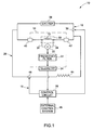
- FIG. 1 is a schematic view of a generator having a superconductive rotor coil and a quench protection system for protecting the superconductive rotor coil from damage due to quenching in the superconductive rotor coil, in accordance with an exemplary embodiment of the present technique;
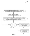
- FIG. 2 is a flow chart illustrating a method of quench protection for the superconductive rotor coil of FIG. 1;
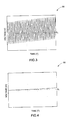
- FIG 3 is a graph of superconductive rotor coil voltage versus time, in accordance with an exemplary embodiment of the present technique;
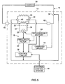
- FIG. 4 is a graph of superconductive rotor coil voltage filtered to block superconductive rotor coil voltage signals that are not representative of a change in coil voltage caused by quenching; and
- FIG. 5 is a detailed view of a quench protection system for the superconductive rotor coil in accordance with another aspect of the present technique.
- Referring now to FIG 1, a rotating electrical machine is illustrated, and represented generally by
reference numeral 10. In this embodiment, the rotatingelectrical machine 10 is a generator. However, the techniques described below are applicable to motors, as well as generators. In addition, the techniques may be used in other systems that utilize superconductors, such as medical imaging systems. In this embodiment, thegenerator 10 has a high temperaturesuperconductive rotor coil 12 that is disposed on arotor 14. Thesuperconductive rotor coil 12 produces a magnetic field from electricity that it receives from anexciter circuit 16. Examples of exciter circuits may include DC exciter circuit AC exciter circuit, static exciter circuit or the like. Theexciter circuit 16 is explained in more detail below. When the electrical current flowing through thesuperconductive rotor coil 12 exceeds the critical current, a portion of thesuperconductive rotor coil 12 loses its superconductivity and a quench condition in thesuperconductive rotor coil 12 may result. - A
quench protection system 18 is provided to protect thesuperconductive rotor coil 12 from damage due to a quench condition. Thequench protection system 18 is operable to detect an increase in the resistance of thesuperconductive rotor coil 12 as a result of resistive heating before a quench condition exists in therotor coil 12. This enables thesystem 18 to act to prevent damage to therotor coil 12 before the quench condition exists. The quench condition may be detected based on an increase in voltage across thecoil 12 caused by the increase in electrical resistance of the portions of thecoil 12 experiencing resistive heating. As the resistive heating propagates through thesuperconductive rotor coil 12, the volume of thecoil 12 contributing to the increase in resistance of thecoil 12 increases, increasing the voltage across thecoil 12. However, voltages also are induced in thesuperconductive rotor coil 12 during normal operation. For example, voltage changes may be induced in therotor coil 12 by external magnetic fields and by changes in the load on the generator. It is therefore difficult to distinguish voltage increase due to resistive heating or a quench from the relatively large voltages induced in thecoil 12. However, the present system is operable to determine whether the increase in voltage across the rotor coil is due to normal operation or a quench condition. - In the illustrated embodiment, the
quench protection system 18 comprises avoltage detector 20, afrequency filter 22, atelemetry system 24, acontrol circuit 26, and adump circuit 28. A disadvantage of prior techniques is that it was difficult to detect the superconductive rotor coil voltage accurately across the rotating superconducting coil because the quench detection circuit was typically located on a stationary portion of the generator away from the rotor. - However, in this embodiment, the
voltage detector 20 is disposed on therotor 14 and is coupled directly across thecoil 12. - The
voltage detector 20 is operable to transmit a signal representative of the voltage across therotor coil 12 to thecontrol circuit 26 via thefrequency filter 22. In this embodiment, thefrequency filter 22 is a low pass filter. The low pass filter is selected to block voltage signals that are not representative of an increase in voltage across therotor coil 12 caused by a quench condition. Upon receipt of the signal from thefrequency filter 22, thecontrol circuit 26 determines if a quench condition exists in therotor coil 12. If a quench condition exists, the control circuit may remove or reduce power to therotor coil 12, or direct thequench protection system 18 to take other actions to protect thesuperconductive rotor coil 12 from any damage that may be caused by the quench condition. In addition, thecontrol circuit 26 is operable to direct thedump circuit 28 to discharge the magnetic energy stored in thecoil 12 when a quench condition is detected. - In this embodiment, the
voltage detector 20 is disposed on therotor 14. Furthermore, in accordance with the embodiment illustrated in FIG 1, thefrequency filter 22, thecontrol circuit 26, and thedump circuit 28 are displaced away from therotor 14. However, one or more of these devices may be disposed on therotor 14. Anelectromagnetic induction shield 30 is disposed around thesuperconductive rotor coil 12. Thevoltage detector 20 hasconductive leads electromagnetic induction shield 30 to thesuperconductive rotor coil 12. - The illustrated embodiment utilizes the
telemetry system 24 to transmit the signal representative of superconductive rotor coil voltage from thevoltage detector 20 to the portions of the quenchprotection system 18 located externally of therotor 14, such as thecontrol circuit 26. Thefrequency filter 22 receives the signal representative of voltage across thesuperconductive rotor coil 12 from thevoltage detector 20 and blocks signals that are not related to the detection of a quench condition in thesuperconductive rotor coil 12, such as electrical noise and voltages induced in therotor coil 12 by external magnetic fields. For example, thefrequency filter 22 may block signals having a frequency outside an expected frequency range for signals representative of an increase in voltage due to an increase in resistive heating in thecoil 12. Conversely, thefilter 22 enables signals having a frequency within the expected frequency range to pass to thecontrol circuit 26. Thecontrol circuit 26 receives the output of thefrequency filter 22 and uses the output to establishes whether or not resistive heating or a quench condition is occurring in thesuperconductive rotor coil 12. - As noted above, the
superconductive rotor coil 12 receives electricity from theexciter circuit 16. Theexciter circuit 16 comprises anexciter 36, aswitch 38, andslip rings exciter 36 produces an electric current. The slip rings 40 and 42 couple the electrical current from theexciter 36, which is stationary, to therotor 14, which is rotating. Theswitch 38 is controlled by thecontrol circuit 26. Theswitch 38 may be opened by thecontrol circuit 26 to prevent current from flowing from the exciter to thesuperconductive rotor coil 12. Theexciter 36 may also be used to provide power to thevoltage detector 20, thefrequency filter 22, thecontrol circuit 26, and thedump circuit 28. - The
dump circuit 28 comprises adump resistor 44 and aswitch 46. Theswitch 46 is controlled by thecontrol circuit 26. As discussed above, thecontrol circuit 26 opens theexciter circuit switch 38 when a rise in voltage due to a quench condition is detected across therotor coil 12. In addition, thecontrol circuit 26 closes thedump circuit switch 46. When thedump circuit switch 46 is closed, a circuit is completed between thesuperconductive rotor coil 12 and thedump resistor 44. This provides a path for thesuperconductive rotor coil 12 to discharge the magnetic energy stored in thecoil 12 through thedump resistor 44. The magnetic energy stored in thecoil 12 is converted into electricity and discharged through thedump resistor 44. Thus, in this embodiment, the quenchprotection system 18 is operable to remove the supply of current to thecoil 12 from theexciter 36 and to enable the energy stored in thecoil 12 to be discharged. This prevents further resistive heating of thesuperconductive rotor coil 12. - The voltage across the
superconductive rotor coil 12 may be influenced by external transient faults such as a grid transmission breaker trip or a lightning strike. This may lead the quenchprotection system 18 to believe that a quench condition exists, when in actuality it does not. In the illustrated embodiment, anexternal control system 48 is provided to detect external transient faults. When an external transient fault is detected, theexternal control system 48 may transmit a signal to thecontrol circuit 26 to inform thecontrol circuit 26 of the transient fault. Thecontrol circuit 26 may then disregard, or compensate for, the signal from thevoltage detector 20 until the transient fault has passed to prevent an inadvertent loss of operation. - Referring generally to FIG 2, a method of utilizing the quench
protection system 18 to protect thesuperconductive rotor coil 12 from a quench condition is illustrated, and represented generally byreference numeral 50. Themethod 50 comprises providing a signal representative of voltage across thesuperconductive rotor coil 12, as represented byblock 52. The method also comprises utilizing thefrequency filter 22 to filter the signal to remove voltage signals that are not related to establishing whether a quench condition exists in thesuperconductive rotor coil 12, as represented byblock 54. For example, thefrequency filter 22 may be used to block higher frequencies representative of electrical noise from passing through thefilter 22, while enabling signals having lower frequencies that are representative of an increase in voltage across thecoil 12 due to resistive heating to pass. - The method also comprises providing a reference voltage (Vo) and comparing the filtered superconductive rotor coil voltage signal (Vr) to the reference voltage (Vo), as represented by
block 56. The reference voltage (Vo) is a threshold voltage that represents a voltage increase across thesuperconductive rotor coil 12 due to a defined amount of resistive heating in thecoil 12. The reference voltage (Vo) is utilized to prompt action by thecontrol circuit 26 of quenchprotection system 18. Thecontrol circuit 26 may be used to provide the reference voltage (Vo) and to compare the filtered superconductive rotor coil voltage signal (Vr) to the reference voltage (Vo). The value of the reference voltage (Vo) may be adjusted to produce the desired response. Several factors may be considered in establishing the value of the reference voltage. For example, a low reference voltage may result in spurious indications of a quench condition, causing the quench protection system to operate inadvertently. Conversely, a high reference voltage may result in damage to thecoil 12 from resistive heating before the quenchprotection system 18 can act to protect thecoil 12. - The method also comprises determining whether the filtered superconductive rotor coil voltage signal (Vr) is greater than the reference voltage (Vo) or not, as represented by
block 58. If the filtered superconductive rotor coil voltage (Vr) does not exceed the reference voltage (Vo), the operation of the system continues as normal. However, if the filtered superconductive rotor coil voltage (Vr) exceeds the reference voltage (Vo), thecontrol circuit 26 directs theexciter circuit 16 to remove power to thesuperconductive rotor coil 12, as represented byblock 60. In addition, once theexciter circuit 16 is open, thecontrol circuit 26 activates thedump circuit 28 to discharge the magnetic field in thesuperconductive rotor coil 12, as represented byblock 62. With no current flowing through thecoil 12, no resistive heating can occur in thecoil 12. Thus, thesuperconductive coil 12 is protected from the harmful effects of quenching. - Referring generally to FIG 3 and 4, an example of the operation of the frequency filter in filtering the signal representative of the superconductive rotor coil voltage is illustrated. FIG 3 illustrates a graph of the superconductive rotor coil voltage (V) over time (T) prior to filtering, represented generally by
reference numeral 64. The illustrated example of unfiltered superconductive rotor coil voltage (V) includes an electrical noise component, giving the voltage (V) a generally sinusoidal shape. However, thesuperconductive rotor coil 12 is experiencing resistive heating in this example. - As a result, the voltage (V) is gradually increasing. FIG 4 is a graph of the superconductive rotor coil voltage (Vr) filtered by the
frequency filter 22. The filtered superconductive rotor coil voltage (Vr), represented generally byreference numeral 66, reflects the gradual increase in superconductive rotor coil voltage caused by the resistive heating in thesuperconductive rotor coil 12, and not electrical noise. - Referring generally to FIG 5, an alternative embodiment of a generator having a
superconductive rotor coil 12 is illustrated. In this alternative embodiment, the quenchprotection system 18 functions in a similar manner to the previous embodiment. However, thefrequency filter 22, thecontrol circuit 26, and thedump circuit 28, are disposed on or within therotor 14, rather than a stationary portion of the generator. Thus, no telemetry circuit is provided in this embodiment. Arechargeable battery 68 is provided inside therotor 14. Therechargeable battery 68 is operable to power thevoltage detector 20, thefrequency filter 22, thecontrol circuit 26, and thedump circuit 28. Thebattery 68 is charged by a chargingcircuit 70 operable to remove a predetermined amount of current fed to therotor coil 12 via theexciter circuit 16. Charging of the battery may occur during periods when substantially sufficient voltage is generated across thecoil 12.
Claims (10)
- A rotating electric machine (10), comprising:a rotor (14), comprising:a superconductive rotor coil (12); anda quench protection system (18) operable to protect the superconductive rotor coil (12) from a quench condition, comprising:a voltage detector (20) operable to produce a signal representative of superconductive rotor coil voltage;a circuit coupled to the voltage detector (20) to receive the signal representative of superconductive rotor coil voltage, wherein the circuit is operable to cancel electrical noise from the signal representative of superconductive rotor coil voltage to produce a signal representative of a rise in superconductor rotor voltage over time; anda control circuit (26) communicatively coupled to the circuit, wherein the control circuit (26) is configured to recieve the signal representative of a rise in superconductor rotor voltage over time and to initiate a corrective action to protect the superconductive rotor coil (12) from the quench condition when the signal representative of a rise in superconductor rotor voltage over time exceeds a predefined voltage.
- The machine (10) of claim 1, wherein the circuit comprises a frequency filter (22) communicatively coupled to the voltage detector (20) to receive the signal representative of superconductive rotor coil voltage, wherein the frequency filter (22) is selected to block noise signals and to enable the signal representative of a rise in superconductor rotor voltage over time to pass through the filter (22).
- The machine (10) of claim 2, further comprising an exciter (36) operable to supply current to the superconductive rotor coil (12) and a first switch (38) operable to selectively couple the exciter (36) to the superconductive rotor coil (12), wherein the first switch (38) is controlled by the control circuit (26) and the corrective action comprises opening the first switch (38).
- The machine (10) of claim 3, further comprising a dump resistor (44) and a second switch (46) operable to selectively couple the superconductive rotor coil (12) to the dump resistor (44), wherein the second switch (46) is controlled by the control circuit (26) and the corrective action comprises closing the second switch (46) to enable the superconductive rotor coil (12) to discharge stored magnetic energy through the dump resistor (44).
- The machine (10) of claim 1, wherein the rotor (14) comprises an electromagnetic shield (30) disposed over the superconductive rotor coil (12) and the voltage detector (20) comprises leads (32, 34) extending through the electromagnetic shield (30) to the superconductive rotor coil (12).
- A method of detecting a quench condition in superconductor (12), comprising:detecting voltage across the superconductor;producing a signal representative of voltage across the superconductor (52);removing electrical noise from the signal representative of voltage across the superconductor to produce a signal representative of a voltage across the superconductor due to electrical resistance in the superconductor (54); andcomparing the signal representative of voltage across the superconductor due to electrical resistance in the superconductor to a reference voltage representative of voltage across the superconductor due to a defined electrical resistance in the superconductor (56).
- The method of claim 6, wherein comparing (56) comprises coupling the signal representative of voltage across the superconductor (12) due to electrical resistance in the superconductor (12) to a control circuit (26) operable to produce a signal when the signal representative of voltage across the superconductor (12) due to electrical resistance in the superconductor (12) rises to the reference voltage representative of voltage across the superconductor (12) due to a defined electrical resistance in the superconductor.
- The method of claim 6, wherein removing electrical noise from the signal representative of superconductor voltage (54) comprises coupling the signal representative of voltage across the superconductor (12) through a filter (22) operable to block electrical noise from passing through the filter (22).
- The method of claim 6, further comprising detecting transient conditions on an external circuit coupled to the superconductor (12) and providing a signal representative of the transient condition to the control circuit (26) to direct the control circuit (26) to stand-by until the transient condition passes.
- The method of claim 6, wherein the superconductor (12) is disposed on a rotor (14) of a rotating electrical machine (10), and wherein detecting voltage across the superconductor (12) comprises disposing a voltage detector (20) on the rotor (14) to detect voltage across the superconductor (12).
Applications Claiming Priority (1)
| Application Number | Priority Date | Filing Date | Title |
|---|---|---|---|
| US10/878,589 US7342757B2 (en) | 2004-06-28 | 2004-06-28 | System and method for quench protection of a superconductor |
Publications (1)
| Publication Number | Publication Date |
|---|---|
| EP1612904A2 true EP1612904A2 (en) | 2006-01-04 |
Family
ID=34981205
Family Applications (1)
| Application Number | Title | Priority Date | Filing Date |
|---|---|---|---|
| EP05252677A Withdrawn EP1612904A2 (en) | 2004-06-28 | 2005-04-28 | System and method for quench protection of a superconductor |
Country Status (3)
| Country | Link |
|---|---|
| US (1) | US7342757B2 (en) |
| EP (1) | EP1612904A2 (en) |
| JP (1) | JP4856393B2 (en) |
Cited By (9)
| Publication number | Priority date | Publication date | Assignee | Title |
|---|---|---|---|---|
| WO2008056314A1 (en) * | 2006-11-10 | 2008-05-15 | Koninklijke Philips Electronics N.V. | Detecting quench in a magnetic resonance examination system |
| EP2015441A1 (en) * | 2007-06-14 | 2009-01-14 | Siemens Energy, Inc. | Regenerative static excitation system for superconducting rotor |
| GB2456308A (en) * | 2008-01-09 | 2009-07-15 | Gen Electric | Actively controlling Quench Protection of a Superconducting Magnet |
| US7615998B2 (en) | 2007-01-09 | 2009-11-10 | General Electric Company | Method and apparatus for actively controlling quench protection of a superconducting magnet |
| EP2104198A3 (en) * | 2008-03-19 | 2011-08-17 | General Electric Company | Systems And Methods Involving Protection Of Superconducting Generators For Power Applications |
| EP2348515A4 (en) * | 2008-11-12 | 2014-05-14 | Mitsubishi Heavy Ind Ltd | Superconducting coil quench detector and detection method |
| WO2014207130A1 (en) * | 2013-06-28 | 2014-12-31 | Cern - European Organization For Nuclear Research | Ac-current induced quench protection system |
| GB2525610A (en) * | 2014-04-29 | 2015-11-04 | Siemens Plc | Passive quench propagation circuit for superconducting magnets |
| WO2024054320A1 (en) * | 2022-09-06 | 2024-03-14 | Tula eTechnology, Inc. | Boosted rotor supply circuit and method for improving pulsed electric machine efficiency |
Families Citing this family (14)
| Publication number | Priority date | Publication date | Assignee | Title |
|---|---|---|---|---|
| US7977925B2 (en) * | 2008-04-04 | 2011-07-12 | General Electric Company | Systems and methods involving starting variable speed generators |
| US8542015B2 (en) * | 2011-01-19 | 2013-09-24 | General Electric Company | Apparatus and method for protecting a magnetic resonance imaging magnet during quench |
| CN102903473B (en) | 2011-07-29 | 2016-03-30 | 通用电气公司 | superconducting magnet system |
| US9240681B2 (en) | 2012-12-27 | 2016-01-19 | General Electric Company | Superconducting coil system and methods of assembling the same |
| KR101497809B1 (en) * | 2013-06-24 | 2015-03-02 | 두산엔진주식회사 | System for super conducting electric power homopolar generator |
| DE102014209607A1 (en) * | 2014-05-21 | 2015-11-26 | Bayerische Motoren Werke Aktiengesellschaft | Rotor for a synchronous machine |
| JP6601797B2 (en) * | 2015-10-16 | 2019-11-06 | 国立研究開発法人理化学研究所 | Superconducting magnet device and method for suppressing current drop in case of abnormality |
| EP3407081A1 (en) * | 2017-05-22 | 2018-11-28 | Koninklijke Philips N.V. | Magnetic resonance imaging system with emergency quench |
| CN109917310A (en) * | 2019-01-29 | 2019-06-21 | 兰州大学 | A high-speed synchronous acquisition and protection control system for quench signals in superconducting experiments |
| US10978943B2 (en) * | 2019-04-03 | 2021-04-13 | General Electric Company | System and method for auto-ramping and energy dump for a superconducting wind turbine generator |
| US11521771B2 (en) | 2019-04-03 | 2022-12-06 | General Electric Company | System for quench protection of superconducting machines, such as a superconducting wind turbine generator |
| KR102490080B1 (en) * | 2021-05-31 | 2023-01-18 | 서울대학교산학협력단 | Superconducting coil module |
| CN118801755B (en) * | 2024-06-14 | 2026-01-06 | 湖南大学 | A fault-tolerant control method and system for superconducting motors considering quench failure. |
| WO2026033406A1 (en) | 2024-08-05 | 2026-02-12 | Eni S.P.A. | Method and device for detecting a resistive transition zone in a superconductor |
Family Cites Families (9)
| Publication number | Priority date | Publication date | Assignee | Title |
|---|---|---|---|---|
| US4371943A (en) * | 1980-10-06 | 1983-02-01 | General Dynamics Corporation/Convair Div. | External means for detecting normal zones in superconducting magnets or coils |
| JPS59216499A (en) * | 1983-05-20 | 1984-12-06 | Hitachi Ltd | Field circuit protecting unit for rotary electric machine |
| JPS61254100A (en) * | 1985-05-04 | 1986-11-11 | Hitachi Ltd | Superconductive coil exciting current controller |
| US5067044A (en) * | 1990-03-05 | 1991-11-19 | Westinghouse Electric Corp. | Sensor for detecting a quench in a superconductor using an optical coupling |
| JPH08330128A (en) * | 1995-05-31 | 1996-12-13 | Toyota Motor Corp | Quench detection method for superconducting coil |
| US5650903A (en) * | 1995-11-30 | 1997-07-22 | General Electric Company | Superconducting-magnet electrical circuit having voltage and quench protection |
| US5999383A (en) * | 1998-03-05 | 1999-12-07 | Siemens Westinghouse Power Corporation | Arrangement for detecting quenches in superconducting coils |
| US6445555B1 (en) * | 1999-11-24 | 2002-09-03 | American Superconductor Corporation | Method and apparatus for discharging a superconducting magnet |
| US6420842B1 (en) * | 2000-01-11 | 2002-07-16 | American Superconductor Corporation | Exciter and electronic regulator for rotating machinery |
-
2004
- 2004-06-28 US US10/878,589 patent/US7342757B2/en not_active Expired - Fee Related
-
2005
- 2005-04-27 JP JP2005128822A patent/JP4856393B2/en not_active Expired - Fee Related
- 2005-04-28 EP EP05252677A patent/EP1612904A2/en not_active Withdrawn
Cited By (16)
| Publication number | Priority date | Publication date | Assignee | Title |
|---|---|---|---|---|
| WO2008056314A1 (en) * | 2006-11-10 | 2008-05-15 | Koninklijke Philips Electronics N.V. | Detecting quench in a magnetic resonance examination system |
| US8134368B2 (en) | 2006-11-10 | 2012-03-13 | Koninklijke Philips Electronics N.V. | Detecting quench in a magnetic resonance examination system |
| US7615998B2 (en) | 2007-01-09 | 2009-11-10 | General Electric Company | Method and apparatus for actively controlling quench protection of a superconducting magnet |
| US7876100B2 (en) | 2007-01-09 | 2011-01-25 | General Electric Company | Method and apparatus for actively controlling quench protection of a superconducting magnet |
| EP2015441A1 (en) * | 2007-06-14 | 2009-01-14 | Siemens Energy, Inc. | Regenerative static excitation system for superconducting rotor |
| GB2456308A (en) * | 2008-01-09 | 2009-07-15 | Gen Electric | Actively controlling Quench Protection of a Superconducting Magnet |
| GB2456308B (en) * | 2008-01-09 | 2011-01-26 | Gen Electric | Method and apparatus for actively controlling quench protection of a superconducting magnet |
| EP2104198A3 (en) * | 2008-03-19 | 2011-08-17 | General Electric Company | Systems And Methods Involving Protection Of Superconducting Generators For Power Applications |
| EP2348515A4 (en) * | 2008-11-12 | 2014-05-14 | Mitsubishi Heavy Ind Ltd | Superconducting coil quench detector and detection method |
| WO2014207130A1 (en) * | 2013-06-28 | 2014-12-31 | Cern - European Organization For Nuclear Research | Ac-current induced quench protection system |
| US10069294B2 (en) | 2013-06-28 | 2018-09-04 | CERN—European Organization for Nuclear Research | AC-current induced quench protection system |
| CN105580093B (en) * | 2013-06-28 | 2019-04-12 | 欧洲原子能研究组织 | AC current induction quench protection system |
| GB2525610A (en) * | 2014-04-29 | 2015-11-04 | Siemens Plc | Passive quench propagation circuit for superconducting magnets |
| WO2015165630A1 (en) * | 2014-04-29 | 2015-11-05 | Siemens Plc | Passive quench propagation circuit for superconducting magnets |
| GB2525610B (en) * | 2014-04-29 | 2016-12-14 | Siemens Healthcare Ltd | Passive quench propagation circuit for superconducting magnets |
| WO2024054320A1 (en) * | 2022-09-06 | 2024-03-14 | Tula eTechnology, Inc. | Boosted rotor supply circuit and method for improving pulsed electric machine efficiency |
Also Published As
| Publication number | Publication date |
|---|---|
| US7342757B2 (en) | 2008-03-11 |
| JP4856393B2 (en) | 2012-01-18 |
| JP2006014579A (en) | 2006-01-12 |
| US20050286180A1 (en) | 2005-12-29 |
Similar Documents
| Publication | Publication Date | Title |
|---|---|---|
| US7342757B2 (en) | System and method for quench protection of a superconductor | |
| EP1612903B1 (en) | System and method for quench and over-current protection of superconductor | |
| Gomez et al. | Behavior of induction motor due to voltage sags and short interruptions | |
| KR101875563B1 (en) | Quench detection system for a superconductor fault current limiter | |
| KR20020052171A (en) | Arc-fault detecting circuit breaker system | |
| EP2549611A2 (en) | Fault current limiter | |
| US11171479B2 (en) | Superconducting magnet device and method for limiting current decrease in case of abnormality therein | |
| EP2549501A1 (en) | Fault current limiter | |
| CN119134245B (en) | A detuning device and method for suppressing ferromagnetic resonance in power system | |
| EP2621043A2 (en) | Current Limiter | |
| JP4733989B2 (en) | Kenting monitoring control system and operation method thereof | |
| Choi et al. | Under excitation limiter and its role in preventing excessive synchronous generator stator end-core heating | |
| CN111794913B (en) | System and method for automatic ramping and energy release of superconducting wind turbine generators | |
| Arumugam et al. | A review on turn-turn short circuit fault management | |
| EP0285513B1 (en) | Devices for the detection of the transition into the normal state of a supraconducting winding, in particular of an electric generator, and for protecting such a winding | |
| Gallas et al. | A comparative analysis of loss of excitation protection methods for synchronous generators | |
| Hosseinzadeh et al. | A fast fault detection method for protection of HVDC transmission using voltage of the PMFCL | |
| Pfeffer et al. | Protection of hardware: Powering systems (power converter, normal conducting, and superconducting magnets) | |
| Mozina | Why upgrade the protection and grounding of generators at petroleum and chemical plants? | |
| Graham et al. | Generator protection with a new static negative sequence relay | |
| Nath et al. | A fuzzy logic based overcurrent protection system for induction motor | |
| Chothani et al. | A New technique for monitoring and protection of distribution transformer during single-phasing situation | |
| US2468743A (en) | Protective system | |
| Stinskiy et al. | Inrush Detection Through Current Wave Shape Analysis–Advanced Transformer Protection for Power Grids with IBRs | |
| JP4021399B2 (en) | Instantaneous voltage drop compensation apparatus and method |
Legal Events
| Date | Code | Title | Description |
|---|---|---|---|
| PUAI | Public reference made under article 153(3) epc to a published international application that has entered the european phase |
Free format text: ORIGINAL CODE: 0009012 |
|
| AK | Designated contracting states |
Kind code of ref document: A2 Designated state(s): AT BE BG CH CY CZ DE DK EE ES FI FR GB GR HU IE IS IT LI LT LU MC NL PL PT RO SE SI SK TR |
|
| AX | Request for extension of the european patent |
Extension state: AL BA HR LV MK YU |
|
| STAA | Information on the status of an ep patent application or granted ep patent |
Free format text: STATUS: THE APPLICATION IS DEEMED TO BE WITHDRAWN |
|
| 18D | Application deemed to be withdrawn |
Effective date: 20160317 |