EP1612731B1 - Computermodellierung physikalischer Szenen - Google Patents
Computermodellierung physikalischer Szenen Download PDFInfo
- Publication number
- EP1612731B1 EP1612731B1 EP04013783A EP04013783A EP1612731B1 EP 1612731 B1 EP1612731 B1 EP 1612731B1 EP 04013783 A EP04013783 A EP 04013783A EP 04013783 A EP04013783 A EP 04013783A EP 1612731 B1 EP1612731 B1 EP 1612731B1
- Authority
- EP
- European Patent Office
- Prior art keywords
- image
- images
- neural network
- artificial neural
- region
- Prior art date
- Legal status (The legal status is an assumption and is not a legal conclusion. Google has not performed a legal analysis and makes no representation as to the accuracy of the status listed.)
- Active
Links
Images
Classifications
-
- G—PHYSICS
- G06—COMPUTING; CALCULATING OR COUNTING
- G06T—IMAGE DATA PROCESSING OR GENERATION, IN GENERAL
- G06T7/00—Image analysis
- G06T7/50—Depth or shape recovery
- G06T7/55—Depth or shape recovery from multiple images
- G06T7/593—Depth or shape recovery from multiple images from stereo images
-
- G—PHYSICS
- G06—COMPUTING; CALCULATING OR COUNTING
- G06T—IMAGE DATA PROCESSING OR GENERATION, IN GENERAL
- G06T7/00—Image analysis
- G06T7/30—Determination of transform parameters for the alignment of images, i.e. image registration
Definitions
- the present invention relates generally to image based modeling. More particularly the invention relates to a method of automatically modeling a physical scene according to the preamble of claim 1 and a corresponding apparatus according to the preamble of claim 9. The invention also relates to a computer program according to claim 7 and a computer readable medium according to claim 8.
- Modern image processing has provided us with highly efficient tools for registering the properties of complex physical scenes.
- the advances in computer graphics have also enabled a real time visualization of such scenes.
- a hierarchical neural stereo matching approach for real-time obstacle detection using linear cameras by Ruichek Y, INTELLIGENT TRANSPORTATION SYSTEMS,2003. PROCEEDINGS 2003 IEEE, OCT 12-15, 2003, PISCATAWAY, NJ, USA, IEEE, vol 1, 12 October 2003, pages 299-304,XP010673840, ISBN: 0-7803-8125-4 , describes a hierarchical neural approach for matching edges extracted from stereo linear images.
- Edge stereo matching at different levels is performed with a neural network procedure. At each level, the process starts by selecting edges with respect to their gradient magnitude. The selected edges are then matched in order to obtain reference pairs from which the remaining edges will be matched in the next level.
- the matching task is formulated as an optimization problem where an objective function, representing the constraints on the solution, is minimized thanks to a Hopfield neural network.
- Pollefeys M., "Tutorial on 3D Modeling from Images”, Katholike Universiteit, Leuven, 26 June 2000, Dublin, Irel and, in conjunction with ECCV 2000 describes how a three-dimensional surface model of a scene can be obtained from a sequence of images taken by a freely moving camera.
- Pollefeys proposes that a depth map be created by relating different images of the same objects to one another, for instance based on feature extraction and cross-correlation. The depth map, in turn, forms a basis for a three-dimensional model of the scene in which the objects are included.
- the object of the present invention is therefore to provide an improved three-dimensional modeling a physical scene, which alleviates the above problems and thus offers a means for generating the depth map in real time.
- the object is achieved by the method as initially described, wherein the matching step involves: loading pixel values for a first image portion of the first image into an artificial neural network; scanning, by means of the artificial neural network, the second image in search of pixels representing a second image portion corresponding to the first image portion; and determining a position of the second image portion upon fulfillment of a match criterion in the artificial neural network in respect of the first and second image portions, and the scanning further involves: generating a database which represents image patterns that occur in the first image; and performing the scanning of the second image with support from representations in the database. This is desirable because the database enhances the efficiency of the method.
- This method is advantageous because the artificial neural network allows a prompt shifting between learning and recognition, and thus an efficient non-linear filtering may be obtained. Moreover, the method is completely automatic, and the depth buffer generated thereby is very suitable for use in an image based rendering (IBR) procedure. Consequently, efficient real time visualization may also be accomplished.
- IBR image based rendering
- the matching step includes: dividing the first image into a number of first regions of interest, and for each first region of interest; loading pixel values for the first region of interest into the artificial neural network; scanning, by means of the artificial neural network, the second image in search of a second region corresponding to the first region of interest; and determining a position of the second region in the second image upon fulfillment of a match criterion in the artificial neural network in respect of the first regions of interest and the second region.
- the proposed division of the first image into regions of interest is advantageous because thereby the search performed in the subsequent scanning step may be narrowed substantially.
- the matching step includes an initial filtering sub-step, wherein the first and second images are processed (e.g. high-pass filtered) into corresponding first and at least one second filtered images with respect to which the subsequent steps of the method are performed.
- the matching accuracy is improved.
- the initial filtering step specifically involves applying an edge-detecting operator. This, in turn, further improves the accuracy of the subsequent matching.
- the method includes calibrating the depth map into a metric model of the physical scene. Namely, thereby measurements may easily be performed with respect to the model.
- the object is achieved by a computer program, which is directly loadable into the internal memory of a computer, and includes software for controlling the above proposed method when said program is run on a computer.
- the object is achieved by a computer readable medium, having a program recorded thereon, where the program is to control a computer to perform the above-proposed method.
- the object is achieved by the initially described apparatus, wherein the matching module includes an artificial neural network, which is adapted to match the image objects in the first image against the image objects in the second image by: receiving pixel values for at least one first portion of the first image; scanning the second image in search of pixels representing a respective second portion corresponding to each of the at least one first portion; and determining a position of the respective second portion upon fulfillment of a match criterion in respect of the first and second portions, and the apparatus includes a database into which the artificial neural network is adapted to store representations of image patterns that occur in the first image.
- the artificial neural network is further adapted to perform the scanning of the second image with support from representations in the database. This enhances the efficiency of the apparatus.
- an important advantage attained by this apparatus is that the artificial neural network in the matching module allows a prompt shifting between learning and recognition, which in turn enables an efficient non-linear filtering. As a result, a resourceful real time visualization of the physical scene can be accomplished.
- the matching module includes a dividing means, which is adapted to divide the first image a number of first regions of interest. For each first region of interest, the matching module loads pixel values for the first region of interest into the artificial neural network; scans the second image in search of a second region corresponding to the first region of interest; and determines a position of the second region upon fulfillment of a match criterion in respect of the first region of interest and the second region.
- the image pre-processor includes a filter means, which is adapted to perform an initial filtering, wherein the first and second images are processed into corresponding first and second filtered images with respect to which the dividing means is adapted to perform the subsequent steps.
- This filtering is advantageous because it enhances the dividing means accuracy.
- the filter means includes an edge-detecting operator. Namely, thereby the accuracy is further improved.
- the image interface is adapted to be connected to a camera, which registers the at least two images, and delivers them to the apparatus via the image interface. Thereby, a complete scene registering arrangement is attained.
- the proposed solution uses an entirely passive data registering means. This renders the invention well adapted to military applications, wherein typically stealth is a key issue. Moreover, a passive strategy is generally preferable at long ranges, e.g. outdoors, where active alternatives often become problematic. A passive method is also advantageous because it allows analysis and calculation of the image depth, both in real time and posterior. Additionally, a correct correlation between image buffer and the depth buffer is attained, since the latter is calculated from the former.
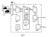
- An apparatus 100 for automatically modeling a physical scene is illustrated by means of a block diagram in figure 1 . It is presumed that the scene to be modeled includes at least one object, such as a building, a vehicle or a tree, which has certain dimensions and surface properties.
- the apparatus 100 includes an image interface 110, an image pre-processor 120, a matching module 130 and at least one calculation module 140 and 150.
- the apparatus 100 also contains a central processing unit 170 for controlling the operation of the other units and modules therein.
- the central processing unit 170 operates according to a computer program, which is stored in a computer readable medium 180 associated with the apparatus 100.
- the image interface 110 is adapted to receive a number of images I 1 and I 2 (at least two) of the scene to be modeled.
- the image interface 110 is adapted to be connected to a camera (e.g. a video camera), which in turn, registers the images I 1 and I 2 .
- a first image I 1 is registered at a first position and a first angle with respect to the scene
- a second image I 2 is registered at a second position and a second angle with respect to the scene.
- the second position and/or the second angle are here different from the first position and/or the first angle, so that the contents of the images I 1 and I 2 are different to some extent.
- the image pre-processor 120 is adapted to adjust the intensity levels of the received images I 1 and I 2 , such that a subsequent image processing is made independent from any initial difference in an absolute intensity level between the received images I 1 and I 2 .
- this pre-processing normally involves a high-pass filtering of the images I 1 and I 2 .
- the matching module 130 is adapted to match image objects in the first image I 1 against image objects in the second image I 2 , and in response thereto produce a matching result M 12 describing a relationship between the first and second images.
- the matching module 130 includes an artificial neural network 133, which is adapted to match the image objects in the first image I 1 against the image objects in the second image I 2 by receiving pixel values for at least one first portion of the first image I 1 . Then, the artificial neural network 133 scans the second image I 2 in search of pixels that represent a respective second portion corresponding to each of the at least one first portion. Upon fulfillment of a match criterion in respect of the first and second portions, the artificial neural network 133 determines a position of the respective second portion, and delivers a matching result M 12 that reflects this information.
- the matching module 130 is associated with, or includes, a database 134 into which the artificial neural network 133 is adapted to store representations R 1 of image patterns that occur in the first image.
- the artificial neural network 133 is then further adapted to perform the scanning of the second image I 2 with support from representations R 1 in the database 134.
- the matching module 130 includes a dividing means 132, which is adapted to divide the first image I 1 into a number of first regions of interest. For each first region of interest the matching module 130 loads pixel values for the first region of interest into the artificial neural network 133; controls the artificial neural network 133 to scan the second image I 1 in search of a second region corresponding to the first region of interest; and upon fulfillment of a match criterion in respect of the first region of interest and second region, determines a position of the second region.
- the image pre-processor 120 contains a filter means, such as an edge-detecting operator, which is adapted to perform an initial filtering of the first and second images I 1 and I 2 .
- the filter means process the images I 1 , and I 2 into corresponding first and second filtered images I 1F and I 2F with respect to which the dividing means 132 is adapted to perform the subsequent steps.
- a first calculation module 140 is adapted to receive the matching result M 12 from the matching module 130. Based on this matching result M 12 , the first calculation module 140 calculates a fundamental matrix F 12 that defines a relationship between the first image I 1 and the second image I 2 . In order to produce the fundamental matrix F 12 , however, several matches are required (typically at least nine). For example, the fundamental matrix F 12 may describe dispersions (or differences) in pixel values between the images I 1 and I 2 .
- a second calculation module 150 is adapted to receive the fundamental matrix F 12 , and based thereon calculate a depth map D 12 , which describes distance differences (i.e. depths) between a set of image points in the first image I 1 and a corresponding set of image points in the second image I 2 .
- the fundamental matrix- and depth map calculations may equally well be performed in a single module or unit, as in the above-described two modules 140 and 150.
- the apparatus 100 includes a calibrating means 160, which is adapted to calibrate the depth map D 12 into a metric model D 12-m of the physical scene.
- the model may be used to perform adequate measurements of the physical scene.
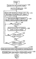
- a first step 205 receives at least two images of the scene, for example from a still image- or a video camera. For reasons of a clear presentation, however, the following procedure presumes that only two images are received. Nevertheless, according to the invention, the procedure is applicable to any number of images higher than or equal to two. In any case, a first image of these images is presumed to be registered at a first position and a first angle with respect to the scene, and a second image is presumed to be registered at a second position and a second angle with respect to the scene, where at least one of the second position and the second angle is different from the first position and the first angle.
- a step 210 pre-processes the received images by adjusting the intensity levels of the images, such that a subsequent image processing is made independent from any initial difference in an absolute intensity level between the received images.
- a step 215 loads pixel values for an image portion of the first image into an artificial neural network.
- a step 220 scans the second image in search of pixels representing a second image portion corresponding to the first image portion.
- a following step 225 investigates whether a match is found, and if so a step 230 follows. Otherwise, the procedure loops back to the step 220.
- the step 230 determines a position of the second image portion where the artificial neural network found that the match criterion was fulfilled. Then, a step 235 checks whether the entire second image has yet been scanned, and if not the procedure loops back to the step 220, so that the search may continue after any better matches. If the step 235 finds that the entire second image has been scanned a step 240 checks whether there exist any additional image portions of the first image to match against the second image, and if so the procedure loops back to the step 215. Otherwise, a matching result is produced based on the (possibly iterated) matches determined in the step 230, and a step 245 follows. Here, a fundamental matrix is calculated, which defines a relationship between the first image and the second image.
- a step 250 calculates, based on the fundamental matrix, a depth map that describes distance differences between a set of image points in the first image and a corresponding set of image points in the second image. Finally, this depth map serves as a basis for generating the model of the physical scene registered by the at least two images.
- All of the process steps, as well as any sub-sequence of steps, described with reference to the figure 2 above may be controlled by means of a programmed computer apparatus.
- the embodiments of the invention described above with reference to the drawings comprise computer apparatus and processes performed in computer apparatus, the invention thus also extends to computer programs, particularly computer programs on or in a carrier, adapted for putting the invention into practice.
- the program may be in the form of source code; object code, a code intermediate source and object code such as in partially compiled form, or in any other form suitable for use in the implementation of the process according to the invention.
- the carrier may be any entity or device capable of carrying the program.
- the carrier may comprise a storage medium, such as a Flash memory, a ROM (Read Only Memory), for example a CD (Compact Disc) or a semiconductor ROM, an EPROM (Erasable Programmable Read-Only Memory), an EEPROM (Electrically Erasable Programmable Read-Only Memory), or a magnetic recording medium, for example a floppy disc or hard disc.
- the carrier may be a transmissible carrier such as an electrical or optical signal which may be conveyed via electrical or optical cable or by radio or by other means.
- the carrier may be constituted by such cable or device or means.
- the carrier may be an integrated circuit in which the program is embedded, the integrated circuit being adapted for performing, or for use in the performance of, the relevant processes.
Claims (15)
- Verfahren zum automatischen Modellieren einer physikalischen Szene mit einer Anzahl von Objekten,
wobei das Verfahren umfasst:Empfangen von zumindest zwei Bildern (I1, I2) der Szene, wobei von den Bildern ein erstes Bild (I1) bei einer ersten Position und einem ersten Winkel mit Bezug auf die Szene aufgezeichnet ist und ein zweites Bild (I2) bei einer zweiten Position und einem zweiten Winkel mit Bezug auf die Szene aufgezeichnet ist, wobei zumindest einer von der zweiten Position und dem zweiten Winkel sich von der ersten Position und dem ersten Winkel unterscheidet,Anpassen von zumindest einem Bildobjekt in dem ersten Bild (I1) gegen zumindest ein Bildobjekt in dem zweiten Bild (I2) , um ein Anpassungsergebnis (M12) zu erhalten,Berechnen, auf Grundlage des Anpassungsergebnisses (M12) einer Fundamentalmatrix (F12), die eine Beziehung zwischen dem ersten Bild (I1) und dem zweiten Bild (I2) definiert, undBerechnen, auf Grundlage der Fundamentalmatrix (F12), einer Tiefenabbildung (D12) , die Distanzunterschiede zwischen einem Satz von Bildpunkten in dem ersten Bild (I1) und einem entsprechenden Satz von Bildpunkten in dem zweiten Bild (I2) beschreibt, dadurch gekennzeichnet, dass der Anpassungsschritt umfasst:wobei das Scannen ferner beinhaltet:Laden von Pixelwerten für einen ersten Bildteil des ersten Bildes (I1) in ein künstliches neuronales Netzwerk (133),Scannen, mittels des künstlichen neuronalen Netzwerkes (133), des zweiten Bildes (I2) bei der Suche nach Pixel, die einen zweiten Bildteil abbildern, der einem ersten Bildteil entspricht, undBestimmen einer Position des zweiten Bildteiles nach dem Erfüllen eines Anpassungskriteriums in dem künstlichen neuronalen Netzwerk (133) in Bezug auf die ersten und zweiten Bildteile,Generieren einer Datenbank (134), die Bildmuster abbildet, die in dem ersten Bild (I1) auftreten, undDurchführen des Scannens des zweiten Bildes (I2) mit Unterstützung von Abbildungen (R1) in der Datenbank (134). - Verfahren nach Anspruch 1, dadurch gekennzeichnet, dass der Anpassungsschritt umfasst
Aufteilen des ersten Bildes (I1) in eine Anzahl von Interessenbereiche, und für jeden ersten Interessenbereich
Laden von Pixelwerten für den ersten Interessenbereich in das künstliche neuronale Netzwerk (133),
Scannen, mittels des künstlichen neuronalen Netzwerkes (133), des zweiten Bildes (I2) bei der Suche einem zweiten Bereich, der dem ersten Interessenbereich entspricht, und
Bestimmen einer Position des zweiten Bereichs in dem zweiten Bild (I2) nach dem Erfüllen eines Anpassungskriteriums in dem künstlichen neuronalen Netzwerk (133) in Bezug auf die ersten Interessenbereiche und den zweiten Bereich. - Verfahren nach Anspruch 2, dadurch gekennzeichnet, dass der Anpassungsschritt einen anfänglichen Filter-Unterschritt umfasst, in dem das erste und zweite Bild (I1, I2) in ein entsprechendes erstes und zumindest ein zweites gefiltertes Bild (I1F, I2F) verarbeitet werden, bezüglich derer die anschließenden Verfahrensschritte durchgeführt werden.
- Verfahren nach Anspruch 3, dadurch gekennzeichnet, dass der anfängliche Filter-Schritt beinhaltet, einen Randerfassungsoperator anzuwenden.
- Verfahren nach irgendeinem der vorhergehenden Ansprüche, gekennzeichnet durch ein Kalibrieren der Tiefenabbildung (D12) in ein Metrik-Modell der physikalischen Szene.
- Verfahren nach irgendeinem der vorhergehenden Ansprüche, gekennzeichnet durch eine Vorverarbeitung der empfangenen Bilder (I1, I2) durch Anpassen der Bilder- (I1, I2) Intensitätslevel, so dass eine anschließende Bildverarbeitung unabhängig von irgendeinem anfänglichen Unterschied in einem absoluten Intensitätslevel zwischen den empfangenen Bildern (I1, I2) gemacht wird.
- Computerprogramm, das direkt in die interne Speichereinheit eines Computers ladbar ist, das eine Software zum Steuern der Schritte von irgendeinem der Ansprüche 1 - 6 umfasst, wenn das Programm auf dem Computer läuft.
- Computer-lesbares Medium (180) mit einem darauf aufgenommenen Programm, wobei das Programm ausgelegt ist, so dass ein Computer die Schritte von irgendeinem der Ansprüche 1 - 6 steuert.
- Vorrichtung (100) zum automatischen Modellieren einer physikalischen Szene mit einer Anzahl von Objekten, wobei die Vorrichtung umfasst:eine Bild-Schnittstelle (110), ausgelegt zum Empfangen von zumindest zwei Bildern (I1, I2) von der Szene, wobei von den Bildern ein erstes Bild (I1) bei einer ersten Position und einem ersten Winkel mit Bezug auf die Szene aufgezeichnet ist und ein zweites Bild (I2) bei einer zweiten Position und einem zweiten Winkel mit Bezug auf die Szene aufgezeichnet ist, wobei zumindest einer von der zweiten Position und dem zweiten Winkel sich von der ersten Position und dem ersten Winkel unterscheidet,ein Anpassungsmodul (130), ausgelegt zum Anpassen von Bildobjekten in dem ersten Bild (I1) gegen Bildobjekte in dem zweiten Bild (I2), und als Antwort darauf ein Anpassungsresultat (M12) produziert,ein erstes Berechnungsmodul (140), ausgelegt zum Empfangen der Anpassungsresultate (M12), und auf Grundlage dessen eine Fundamentalmatrix (F12) berechnet, die eine Beziehung zwischen dem ersten Bild (I1) und dem zweiten Bild (I2) definiert, undein zweites Berechnungsmodul (150), ausgelegt zum Empfangen der Fundamentalmatrix (F12), und auf Grundlage dessen eine Tiefenabbildung (D12) berechnet, die einen Distanzunterschied zwischen einem Satz von Bildpunkten in dem ersten Bild (I1) und einem entsprechenden Satz von Bildpunkten in dem zweiten Bild (I2) beschreibt,dadurch gekennzeichnet, dass
das Anpassungsmodul (130) ein künstliche neuronales Netzwerk (133) umfasst, dass ausgelegt ist zum Anpassen der Bildobjekte in dem ersten Bild (I1) gegen die Bildobjekte in dem zweiten Bild (I2), durch
Empfangen von Pixelwerten für zumindest einen ersten Teil des ersten Bildes (I1),
Scannen des zweiten Bildes (I2) bei der Suche nach Pixel, die einen jeweiligen zweiten Teil abbilden, der jedem der zumindest einem ersten Teil entspricht, und
Bestimmen einer Position des jeweils zweiten Teils nach dem Erfüllen eines Anpassungskriteriums in Bezug auf den ersten und zweiten Teil,
und darin, dass die Vorrichtung eine Datenbank (134) umfasst, in der das künstliche neuronale Netzwerk ausgelegt ist zum Speichern von Abbildungen (R1) von Bildmustern, die in dem ersten Bild auftreten, und das künstliche neuronale Netzwerk ferner ausgelegt ist zum Durchführen des Scannen des zweiten Bildes (I2) mit Unterstützung der Abbildungen (R1) in der Datenbank (134). - Vorrichtung (100) nach Anspruch 9, dadurch gekennzeichnet, dass das Anpassungsmodul (130) eine Aufteilungseinrichtung (132) umfasst, die ausgelegt ist zum Aufteilen des ersten Bildes (I1) in eine Anzahl von ersten Interessenbereichen, wobei für jeden ersten Interessenbereich das Anpassungsmodul ausgelegt ist zum
Laden von Pixelwerten für den ersten Interessenbereich in das künstliche neuronale Netzwerk (133),
Scannen des zweiten Bildes (I2) bei der Suche nach einem zweiten Bereich, der dem ersten Interessenbereich entspricht, und
Bestimmen einer Position des zweiten Bereichs nach dem Erfüllen eines Anpassungskriteriums in Bezug auf die ersten Interessenbereiche und den zweiten Bereich. - Vorrichtung (100) nach Anspruch 10, dadurch gekennzeichnet, dass sie einen Bild-Vorprozessor (120) umfasst, der ausgelegt ist zum Anpassen der empfangenen Bilder- (I1, I2) Intensitätslevel, so dass eine anschließende Bildverarbeitung von irgendeinem anfänglichen Unterschied in einem absoluten Intensitätslevel zwischen den empfangenen Bildern (I1, I2) unabhängig gemacht wird.
- Vorrichtung (100) nach Anspruch 11, dadurch gekennzeichnet, dass der Bild-Vorprozessor (120) eine Filtereinrichtung umfasst, die ausgelegt ist zum Durchführen einer anfänglichen Filteroperation, in der das erste und zweite Bild (I1, I2) in entsprechende erste und zweite gefilterte Bilder (I1F, I2F) verarbeitet werden, bezüglich derer die Aufteilungseinrichtung (132) ausgelegt ist, die anschließenden Schritte durchzuführen.
- Vorrichtung (100) nach Anspruch 12, dadurch gekennzeichnet, dass die Filtereinrichtung einen Randerfassungsoperator umfasst.
- Vorrichtung (100) nach irgendeinem der Ansprüche 9 bis 13, dadurch gekennzeichnet, dass sie eine Kalibrierungseinrichtungen (160) umfasst, die ausgelegt ist zum Kalibrieren der Tiefenabbildung (D12) in einem Metrik-Modell (D12-m) der physikalischen Szene.
- Vorrichtung (100) nach irgendeinen der Anspruche 9 - 14, dadurch gekennzeichnet, dass die Bild-Schnittstelle (110) ausgelegt ist, um mit einer Kamera verbunden zu sein, wobei die Kamera ausgelegt ist, die zumindest zwei Bilder (I1, I2) aufzuzeichnen und die Bilder (I1, I2) an die Vorrichtung (100) über die Bild-Schnittstelle (110) zu liefern.
Priority Applications (6)
| Application Number | Priority Date | Filing Date | Title |
|---|---|---|---|
| AT04013783T ATE404950T1 (de) | 2004-06-11 | 2004-06-11 | Computermodellierung physikalischer szenen |
| EP04013783A EP1612731B1 (de) | 2004-06-11 | 2004-06-11 | Computermodellierung physikalischer Szenen |
| ES04013783T ES2312881T3 (es) | 2004-06-11 | 2004-06-11 | Modelizacion por computadora de escenas fisicas. |
| DE602004015759T DE602004015759D1 (de) | 2004-06-11 | 2004-06-11 | |
| PCT/EP2005/052640 WO2005122091A1 (en) | 2004-06-11 | 2005-06-08 | Computer modeling of physical scenes |
| US11/570,130 US7813543B2 (en) | 2004-06-11 | 2005-06-08 | Computer modeling of physical scenes |
Applications Claiming Priority (1)
| Application Number | Priority Date | Filing Date | Title |
|---|---|---|---|
| EP04013783A EP1612731B1 (de) | 2004-06-11 | 2004-06-11 | Computermodellierung physikalischer Szenen |
Publications (2)
| Publication Number | Publication Date |
|---|---|
| EP1612731A1 EP1612731A1 (de) | 2006-01-04 |
| EP1612731B1 true EP1612731B1 (de) | 2008-08-13 |
Family
ID=34925334
Family Applications (1)
| Application Number | Title | Priority Date | Filing Date |
|---|---|---|---|
| EP04013783A Active EP1612731B1 (de) | 2004-06-11 | 2004-06-11 | Computermodellierung physikalischer Szenen |
Country Status (6)
| Country | Link |
|---|---|
| US (1) | US7813543B2 (de) |
| EP (1) | EP1612731B1 (de) |
| AT (1) | ATE404950T1 (de) |
| DE (1) | DE602004015759D1 (de) |
| ES (1) | ES2312881T3 (de) |
| WO (1) | WO2005122091A1 (de) |
Cited By (1)
| Publication number | Priority date | Publication date | Assignee | Title |
|---|---|---|---|---|
| US11024021B2 (en) | 2019-02-06 | 2021-06-01 | Primeconcept S.R.L. | Check system of a process subject to execution rules |
Families Citing this family (25)
| Publication number | Priority date | Publication date | Assignee | Title |
|---|---|---|---|---|
| US7698270B2 (en) * | 2004-12-29 | 2010-04-13 | Baynote, Inc. | Method and apparatus for identifying, extracting, capturing, and leveraging expertise and knowledge |
| CN103182174B (zh) | 2007-02-14 | 2015-09-16 | 耐克创新有限合伙公司 | 运动信息的收集和显示 |
| US9030536B2 (en) | 2010-06-04 | 2015-05-12 | At&T Intellectual Property I, Lp | Apparatus and method for presenting media content |
| US9787974B2 (en) | 2010-06-30 | 2017-10-10 | At&T Intellectual Property I, L.P. | Method and apparatus for delivering media content |
| US8918831B2 (en) | 2010-07-06 | 2014-12-23 | At&T Intellectual Property I, Lp | Method and apparatus for managing a presentation of media content |
| US9049426B2 (en) | 2010-07-07 | 2015-06-02 | At&T Intellectual Property I, Lp | Apparatus and method for distributing three dimensional media content |
| US9232274B2 (en) | 2010-07-20 | 2016-01-05 | At&T Intellectual Property I, L.P. | Apparatus for adapting a presentation of media content to a requesting device |
| US9560406B2 (en) | 2010-07-20 | 2017-01-31 | At&T Intellectual Property I, L.P. | Method and apparatus for adapting a presentation of media content |
| US9032470B2 (en) | 2010-07-20 | 2015-05-12 | At&T Intellectual Property I, Lp | Apparatus for adapting a presentation of media content according to a position of a viewing apparatus |
| US8994716B2 (en) | 2010-08-02 | 2015-03-31 | At&T Intellectual Property I, Lp | Apparatus and method for providing media content |
| US8438502B2 (en) | 2010-08-25 | 2013-05-07 | At&T Intellectual Property I, L.P. | Apparatus for controlling three-dimensional images |
| US8947511B2 (en) | 2010-10-01 | 2015-02-03 | At&T Intellectual Property I, L.P. | Apparatus and method for presenting three-dimensional media content |
| US8692827B1 (en) * | 2011-01-24 | 2014-04-08 | Google Inc. | Carving buildings from a three-dimensional model, and applications thereof |
| US8947497B2 (en) | 2011-06-24 | 2015-02-03 | At&T Intellectual Property I, Lp | Apparatus and method for managing telepresence sessions |
| US9445046B2 (en) | 2011-06-24 | 2016-09-13 | At&T Intellectual Property I, L.P. | Apparatus and method for presenting media content with telepresence |
| US9602766B2 (en) | 2011-06-24 | 2017-03-21 | At&T Intellectual Property I, L.P. | Apparatus and method for presenting three dimensional objects with telepresence |
| US9030522B2 (en) | 2011-06-24 | 2015-05-12 | At&T Intellectual Property I, Lp | Apparatus and method for providing media content |
| US8587635B2 (en) | 2011-07-15 | 2013-11-19 | At&T Intellectual Property I, L.P. | Apparatus and method for providing media services with telepresence |
| KR101875532B1 (ko) * | 2011-11-23 | 2018-07-11 | 엘지이노텍 주식회사 | 계층적 스테레오 매칭 장치 및 방법 |
| IN2013CH05313A (de) * | 2013-11-18 | 2015-05-29 | Nokia Corp | |
| US9836765B2 (en) | 2014-05-19 | 2017-12-05 | Kibo Software, Inc. | System and method for context-aware recommendation through user activity change detection |
| US10460511B2 (en) * | 2016-09-23 | 2019-10-29 | Blue Vision Labs UK Limited | Method and system for creating a virtual 3D model |
| JP7013578B2 (ja) * | 2017-11-03 | 2022-01-31 | グーグル エルエルシー | 単視点深度予測のための絞りの監視 |
| CN109087383B (zh) * | 2018-08-06 | 2023-01-06 | 林嘉恒 | 组合式偏差分离特征提取扫描方法及系统 |
| WO2020176873A1 (en) | 2019-02-28 | 2020-09-03 | Stats Llc | System and method for generating trackable video frames from broadcast video |
Family Cites Families (2)
| Publication number | Priority date | Publication date | Assignee | Title |
|---|---|---|---|---|
| US5644651A (en) * | 1995-03-31 | 1997-07-01 | Nec Research Institute, Inc. | Method for the estimation of rotation between two frames via epipolar search for use in a three-dimensional representation |
| US6556704B1 (en) * | 1999-08-25 | 2003-04-29 | Eastman Kodak Company | Method for forming a depth image from digital image data |
-
2004
- 2004-06-11 EP EP04013783A patent/EP1612731B1/de active Active
- 2004-06-11 ES ES04013783T patent/ES2312881T3/es active Active
- 2004-06-11 DE DE602004015759T patent/DE602004015759D1/de active Active
- 2004-06-11 AT AT04013783T patent/ATE404950T1/de not_active IP Right Cessation
-
2005
- 2005-06-08 US US11/570,130 patent/US7813543B2/en active Active
- 2005-06-08 WO PCT/EP2005/052640 patent/WO2005122091A1/en active Application Filing
Cited By (1)
| Publication number | Priority date | Publication date | Assignee | Title |
|---|---|---|---|---|
| US11024021B2 (en) | 2019-02-06 | 2021-06-01 | Primeconcept S.R.L. | Check system of a process subject to execution rules |
Also Published As
| Publication number | Publication date |
|---|---|
| WO2005122091A1 (en) | 2005-12-22 |
| ES2312881T3 (es) | 2009-03-01 |
| US7813543B2 (en) | 2010-10-12 |
| DE602004015759D1 (de) | 2008-09-25 |
| US20070250465A1 (en) | 2007-10-25 |
| EP1612731A1 (de) | 2006-01-04 |
| ATE404950T1 (de) | 2008-08-15 |
Similar Documents
| Publication | Publication Date | Title |
|---|---|---|
| EP1612731B1 (de) | Computermodellierung physikalischer Szenen | |
| Guindel et al. | Automatic extrinsic calibration for lidar-stereo vehicle sensor setups | |
| US9990736B2 (en) | Robust anytime tracking combining 3D shape, color, and motion with annealed dynamic histograms | |
| David et al. | Softposit: Simultaneous pose and correspondence determination | |
| US9984280B2 (en) | Object recognition system using left and right images and method | |
| CN109934847B (zh) | 弱纹理三维物体姿态估计的方法和装置 | |
| US11082633B2 (en) | Method of estimating the speed of displacement of a camera | |
| US8009899B2 (en) | Image filling methods | |
| Munoz-Banon et al. | Targetless camera-lidar calibration in unstructured environments | |
| US20210397907A1 (en) | Methods and Systems for Object Detection | |
| KR102223484B1 (ko) | 식생을 제거한 절토사면의 3차원 모델 생성 시스템 및 3차원 모델 생성 방법 | |
| JP3333721B2 (ja) | 領域検出装置 | |
| CN115063447A (zh) | 一种基于视频序列的目标动物运动追踪方法及相关设备 | |
| JP2016148956A (ja) | 位置合わせ装置、位置合わせ方法及び位置合わせ用コンピュータプログラム | |
| US20230350418A1 (en) | Position determination by means of neural networks | |
| JPH07103715A (ja) | 視覚に基く三次元位置および姿勢の認識方法ならびに視覚に基く三次元位置および姿勢の認識装置 | |
| CN115511970B (zh) | 一种面向自主泊车的视觉定位方法 | |
| Lin et al. | Marker-less registration based on template tracking for augmented reality | |
| JP2005141655A (ja) | 3次元モデリング装置及び3次元モデリング方法 | |
| Santamaría et al. | Tackling the coplanarity problem in 3D camera calibration by means of fuzzy landmarks: a performance study in forensic craniofacial superimposition | |
| US20200364521A1 (en) | Trained network for fiducial detection | |
| KR100606615B1 (ko) | 물체인식 방법 | |
| CN116067360B (zh) | 一种基于双重约束的机器人地图构建方法、存储介质及设备 | |
| US20230298203A1 (en) | Method for selecting surface points from a cad model for locating industrial 3d objects, application of this method to the location of industrial 3d objects, and augmented reality system usi | |
| Harribhai | Using regions of interest to track landmarks for RGBD simultaneous localisation and mapping |
Legal Events
| Date | Code | Title | Description |
|---|---|---|---|
| PUAI | Public reference made under article 153(3) epc to a published international application that has entered the european phase |
Free format text: ORIGINAL CODE: 0009012 |
|
| AK | Designated contracting states |
Kind code of ref document: A1 Designated state(s): AT BE BG CH CY CZ DE DK EE ES FI FR GB GR HU IE IT LI LU MC NL PL PT RO SE SI SK TR |
|
| AX | Request for extension of the european patent |
Extension state: AL HR LT LV MK |
|
| AKX | Designation fees paid | ||
| 17P | Request for examination filed |
Effective date: 20060201 |
|
| RBV | Designated contracting states (corrected) |
Designated state(s): AT BE BG CH CY CZ DE DK EE ES FI FR GB GR HU IE IT LI LU MC NL PL PT RO SE SI SK TR |
|
| REG | Reference to a national code |
Ref country code: DE Ref legal event code: 8566 |
|
| 17Q | First examination report despatched |
Effective date: 20061010 |
|
| GRAP | Despatch of communication of intention to grant a patent |
Free format text: ORIGINAL CODE: EPIDOSNIGR1 |
|
| GRAS | Grant fee paid |
Free format text: ORIGINAL CODE: EPIDOSNIGR3 |
|
| GRAA | (expected) grant |
Free format text: ORIGINAL CODE: 0009210 |
|
| AK | Designated contracting states |
Kind code of ref document: B1 Designated state(s): AT BE BG CH CY CZ DE DK EE ES FI FR GB GR HU IE IT LI LU MC NL PL PT RO SE SI SK TR |
|
| REG | Reference to a national code |
Ref country code: GB Ref legal event code: FG4D |
|
| REG | Reference to a national code |
Ref country code: CH Ref legal event code: EP |
|
| REG | Reference to a national code |
Ref country code: IE Ref legal event code: FG4D |
|
| REF | Corresponds to: |
Ref document number: 602004015759 Country of ref document: DE Date of ref document: 20080925 Kind code of ref document: P |
|
| REG | Reference to a national code |
Ref country code: SE Ref legal event code: TRGR |
|
| PG25 | Lapsed in a contracting state [announced via postgrant information from national office to epo] |
Ref country code: NL Free format text: LAPSE BECAUSE OF FAILURE TO SUBMIT A TRANSLATION OF THE DESCRIPTION OR TO PAY THE FEE WITHIN THE PRESCRIBED TIME-LIMIT Effective date: 20080813 |
|
| PG25 | Lapsed in a contracting state [announced via postgrant information from national office to epo] |
Ref country code: FI Free format text: LAPSE BECAUSE OF FAILURE TO SUBMIT A TRANSLATION OF THE DESCRIPTION OR TO PAY THE FEE WITHIN THE PRESCRIBED TIME-LIMIT Effective date: 20080813 Ref country code: AT Free format text: LAPSE BECAUSE OF FAILURE TO SUBMIT A TRANSLATION OF THE DESCRIPTION OR TO PAY THE FEE WITHIN THE PRESCRIBED TIME-LIMIT Effective date: 20080813 Ref country code: SI Free format text: LAPSE BECAUSE OF FAILURE TO SUBMIT A TRANSLATION OF THE DESCRIPTION OR TO PAY THE FEE WITHIN THE PRESCRIBED TIME-LIMIT Effective date: 20080813 |
|
| REG | Reference to a national code |
Ref country code: ES Ref legal event code: FG2A Ref document number: 2312881 Country of ref document: ES Kind code of ref document: T3 |
|
| PG25 | Lapsed in a contracting state [announced via postgrant information from national office to epo] |
Ref country code: BE Free format text: LAPSE BECAUSE OF FAILURE TO SUBMIT A TRANSLATION OF THE DESCRIPTION OR TO PAY THE FEE WITHIN THE PRESCRIBED TIME-LIMIT Effective date: 20080813 |
|
| PG25 | Lapsed in a contracting state [announced via postgrant information from national office to epo] |
Ref country code: BG Free format text: LAPSE BECAUSE OF FAILURE TO SUBMIT A TRANSLATION OF THE DESCRIPTION OR TO PAY THE FEE WITHIN THE PRESCRIBED TIME-LIMIT Effective date: 20081113 Ref country code: DK Free format text: LAPSE BECAUSE OF FAILURE TO SUBMIT A TRANSLATION OF THE DESCRIPTION OR TO PAY THE FEE WITHIN THE PRESCRIBED TIME-LIMIT Effective date: 20080813 |
|
| PG25 | Lapsed in a contracting state [announced via postgrant information from national office to epo] |
Ref country code: RO Free format text: LAPSE BECAUSE OF FAILURE TO SUBMIT A TRANSLATION OF THE DESCRIPTION OR TO PAY THE FEE WITHIN THE PRESCRIBED TIME-LIMIT Effective date: 20080813 Ref country code: PT Free format text: LAPSE BECAUSE OF FAILURE TO SUBMIT A TRANSLATION OF THE DESCRIPTION OR TO PAY THE FEE WITHIN THE PRESCRIBED TIME-LIMIT Effective date: 20090113 Ref country code: SK Free format text: LAPSE BECAUSE OF FAILURE TO SUBMIT A TRANSLATION OF THE DESCRIPTION OR TO PAY THE FEE WITHIN THE PRESCRIBED TIME-LIMIT Effective date: 20080813 Ref country code: CZ Free format text: LAPSE BECAUSE OF FAILURE TO SUBMIT A TRANSLATION OF THE DESCRIPTION OR TO PAY THE FEE WITHIN THE PRESCRIBED TIME-LIMIT Effective date: 20080813 |
|
| PLBE | No opposition filed within time limit |
Free format text: ORIGINAL CODE: 0009261 |
|
| STAA | Information on the status of an ep patent application or granted ep patent |
Free format text: STATUS: NO OPPOSITION FILED WITHIN TIME LIMIT |
|
| 26N | No opposition filed |
Effective date: 20090514 |
|
| PG25 | Lapsed in a contracting state [announced via postgrant information from national office to epo] |
Ref country code: EE Free format text: LAPSE BECAUSE OF FAILURE TO SUBMIT A TRANSLATION OF THE DESCRIPTION OR TO PAY THE FEE WITHIN THE PRESCRIBED TIME-LIMIT Effective date: 20080813 |
|
| PG25 | Lapsed in a contracting state [announced via postgrant information from national office to epo] |
Ref country code: MC Free format text: LAPSE BECAUSE OF NON-PAYMENT OF DUE FEES Effective date: 20090630 |
|
| REG | Reference to a national code |
Ref country code: CH Ref legal event code: PL |
|
| PG25 | Lapsed in a contracting state [announced via postgrant information from national office to epo] |
Ref country code: CH Free format text: LAPSE BECAUSE OF NON-PAYMENT OF DUE FEES Effective date: 20090630 Ref country code: IE Free format text: LAPSE BECAUSE OF NON-PAYMENT OF DUE FEES Effective date: 20090611 Ref country code: LI Free format text: LAPSE BECAUSE OF NON-PAYMENT OF DUE FEES Effective date: 20090630 |
|
| PG25 | Lapsed in a contracting state [announced via postgrant information from national office to epo] |
Ref country code: PL Free format text: LAPSE BECAUSE OF FAILURE TO SUBMIT A TRANSLATION OF THE DESCRIPTION OR TO PAY THE FEE WITHIN THE PRESCRIBED TIME-LIMIT Effective date: 20080813 |
|
| PG25 | Lapsed in a contracting state [announced via postgrant information from national office to epo] |
Ref country code: GR Free format text: LAPSE BECAUSE OF FAILURE TO SUBMIT A TRANSLATION OF THE DESCRIPTION OR TO PAY THE FEE WITHIN THE PRESCRIBED TIME-LIMIT Effective date: 20081114 |
|
| PG25 | Lapsed in a contracting state [announced via postgrant information from national office to epo] |
Ref country code: LU Free format text: LAPSE BECAUSE OF NON-PAYMENT OF DUE FEES Effective date: 20090611 |
|
| PG25 | Lapsed in a contracting state [announced via postgrant information from national office to epo] |
Ref country code: HU Free format text: LAPSE BECAUSE OF FAILURE TO SUBMIT A TRANSLATION OF THE DESCRIPTION OR TO PAY THE FEE WITHIN THE PRESCRIBED TIME-LIMIT Effective date: 20090214 |
|
| PG25 | Lapsed in a contracting state [announced via postgrant information from national office to epo] |
Ref country code: TR Free format text: LAPSE BECAUSE OF FAILURE TO SUBMIT A TRANSLATION OF THE DESCRIPTION OR TO PAY THE FEE WITHIN THE PRESCRIBED TIME-LIMIT Effective date: 20080813 |
|
| PG25 | Lapsed in a contracting state [announced via postgrant information from national office to epo] |
Ref country code: CY Free format text: LAPSE BECAUSE OF FAILURE TO SUBMIT A TRANSLATION OF THE DESCRIPTION OR TO PAY THE FEE WITHIN THE PRESCRIBED TIME-LIMIT Effective date: 20080813 |
|
| REG | Reference to a national code |
Ref country code: FR Ref legal event code: PLFP Year of fee payment: 13 |
|
| REG | Reference to a national code |
Ref country code: FR Ref legal event code: PLFP Year of fee payment: 14 |
|
| REG | Reference to a national code |
Ref country code: FR Ref legal event code: PLFP Year of fee payment: 15 |
|
| PGFP | Annual fee paid to national office [announced via postgrant information from national office to epo] |
Ref country code: FR Payment date: 20230329 Year of fee payment: 20 |
|
| PGFP | Annual fee paid to national office [announced via postgrant information from national office to epo] |
Ref country code: SE Payment date: 20230316 Year of fee payment: 20 Ref country code: IT Payment date: 20230320 Year of fee payment: 20 |
|
| PGFP | Annual fee paid to national office [announced via postgrant information from national office to epo] |
Ref country code: DE Payment date: 20230324 Year of fee payment: 20 |
|
| PGFP | Annual fee paid to national office [announced via postgrant information from national office to epo] |
Ref country code: GB Payment date: 20230412 Year of fee payment: 20 Ref country code: ES Payment date: 20230704 Year of fee payment: 20 |