EP1612472A2 - Vehicle lighting apparatus - Google Patents
Vehicle lighting apparatus Download PDFInfo
- Publication number
- EP1612472A2 EP1612472A2 EP05013959A EP05013959A EP1612472A2 EP 1612472 A2 EP1612472 A2 EP 1612472A2 EP 05013959 A EP05013959 A EP 05013959A EP 05013959 A EP05013959 A EP 05013959A EP 1612472 A2 EP1612472 A2 EP 1612472A2
- Authority
- EP
- European Patent Office
- Prior art keywords
- bulb
- lighting apparatus
- vehicle lighting
- reflective surface
- light
- Prior art date
- Legal status (The legal status is an assumption and is not a legal conclusion. Google has not performed a legal analysis and makes no representation as to the accuracy of the status listed.)
- Granted
Links
Images


Classifications
-
- F—MECHANICAL ENGINEERING; LIGHTING; HEATING; WEAPONS; BLASTING
- F21—LIGHTING
- F21V—FUNCTIONAL FEATURES OR DETAILS OF LIGHTING DEVICES OR SYSTEMS THEREOF; STRUCTURAL COMBINATIONS OF LIGHTING DEVICES WITH OTHER ARTICLES, NOT OTHERWISE PROVIDED FOR
- F21V9/00—Elements for modifying spectral properties, polarisation or intensity of the light emitted, e.g. filters
- F21V9/04—Elements for modifying spectral properties, polarisation or intensity of the light emitted, e.g. filters for filtering out infrared radiation
-
- F—MECHANICAL ENGINEERING; LIGHTING; HEATING; WEAPONS; BLASTING
- F21—LIGHTING
- F21S—NON-PORTABLE LIGHTING DEVICES; SYSTEMS THEREOF; VEHICLE LIGHTING DEVICES SPECIALLY ADAPTED FOR VEHICLE EXTERIORS
- F21S41/00—Illuminating devices specially adapted for vehicle exteriors, e.g. headlamps
- F21S41/10—Illuminating devices specially adapted for vehicle exteriors, e.g. headlamps characterised by the light source
- F21S41/19—Attachment of light sources or lamp holders
-
- F—MECHANICAL ENGINEERING; LIGHTING; HEATING; WEAPONS; BLASTING
- F21—LIGHTING
- F21S—NON-PORTABLE LIGHTING DEVICES; SYSTEMS THEREOF; VEHICLE LIGHTING DEVICES SPECIALLY ADAPTED FOR VEHICLE EXTERIORS
- F21S41/00—Illuminating devices specially adapted for vehicle exteriors, e.g. headlamps
- F21S41/30—Illuminating devices specially adapted for vehicle exteriors, e.g. headlamps characterised by reflectors
- F21S41/32—Optical layout thereof
- F21S41/33—Multi-surface reflectors, e.g. reflectors with facets or reflectors with portions of different curvature
- F21S41/334—Multi-surface reflectors, e.g. reflectors with facets or reflectors with portions of different curvature the reflector consisting of patch like sectors
-
- F—MECHANICAL ENGINEERING; LIGHTING; HEATING; WEAPONS; BLASTING
- F21—LIGHTING
- F21S—NON-PORTABLE LIGHTING DEVICES; SYSTEMS THEREOF; VEHICLE LIGHTING DEVICES SPECIALLY ADAPTED FOR VEHICLE EXTERIORS
- F21S41/00—Illuminating devices specially adapted for vehicle exteriors, e.g. headlamps
- F21S41/60—Illuminating devices specially adapted for vehicle exteriors, e.g. headlamps characterised by a variable light distribution
- F21S41/68—Illuminating devices specially adapted for vehicle exteriors, e.g. headlamps characterised by a variable light distribution by acting on screens
- F21S41/683—Illuminating devices specially adapted for vehicle exteriors, e.g. headlamps characterised by a variable light distribution by acting on screens by moving screens
Definitions
- the present invention relates to a vehicle lighting apparatus of a side-inserting bulb type, in which a bulb is fitted in a direction intersecting with an optical axis, and, more particularly, to a vehicle lighting apparatus by which an ideal light distribution pattern can be obtained from a near-infrared projector and a lamp for a low-beam distribution pattern, an the like.
- vehicle lighting apparatuses are of a longitudinal-inserting bulb type, in which the bulb is fitted in parallel to an optical axis, making a bulb axis parallel to the optical axis.
- the insertion hole for the bulb is provided in a part of the reflective surface, which is closest to the bulb filament and which is a spot that can potentially reflect the light from the bulb most efficiently, thereby compromising the efficiency with which the light is reflected.
- the conventional vehicle lighting apparatus includes a reflector plate and a reflective surface provided on the base.
- the reflector plate is provided with a bulb, a slot into which the bulb is inserted, and a lamp holder to which a mounting collar is detachably fitted.
- the reflective surface or a base member is attached to the reflector plate and directs the light from the lamp substantially parallel to as well in a predetermined direction with respect to the optical axis.
- the direction of bulb insertion is at right angles with respect to the optical axis, disposing the lamp axis at right angles with respect to the optical axis.
- the base member directs the light from the lamp substantially parallel to as well as in a predetermined direction with respect to the optical axis.
- the spot on the base member which is closest to the lamp filament and which can potentially reflect the light most efficiently is used for producing reflected light. Therefore, the reflective surface or the base member in the conventional vehicle lighting apparatus is more efficient than in the vehicle lighting apparatus in which the bulb is fitted vertically. Furthermore, the conventional vehicle lighting apparatus is more compact compared to the vehicle lighting apparatus with a longitudinal-inserting bulb.
- a vehicle lighting apparatus includes a bulb having a front end and a rear end; a reflector including an insertion hole for inserting the front end and a mounting portion to which the rear end is detachably mounted; and a reflective surface that is provided on the reflector, and reflects light from the bulb in a predetermined direction.
- the bulb is inserted in a direction intersecting with an optical axis so that a bulb axis intersects with the optical axis on a substantially horizontal cross section.
- the bulb axis is inclined in such a manner that the front end is declined towards a direction of reflection of the light by the reflective surface with respect to the rear end.
- the reference symbol “F” denotes "front” of a vehicle
- the reference symbol “B” denotes “rear” of the vehicle
- the reference symbol “U” denotes "upper side” in a case where the driver faces the front
- the reference symbol “D” denotes “lower side” in a case where the driver faces the front
- the reference symbol “L” denotes "left side” in a case where the driver faces the front
- the reference symbol “R denotes "right side” in a case where the driver faces the front.
- the reference symbol “VU-VD” denotes “vertical axis”
- the reference symbol “HL-HR” denotes "horizontal axis”.
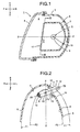
- a first embodiment of the vehicle lighting apparatus according to the present invention is explained next with reference to Fig. 1 through Fig. 5.
- the structure of the vehicle lighting apparatus according to the first embodiment is explained first.
- the reference number 1 denotes the vehicle lighting apparatus according to the first embodiment, the vehicle lighting apparatus being a near-infrared projector (or a near-infrared lamp or a near-infrared headlamp).
- the near-infrared projector 1 includes a lamp housing 3 that sections off a lamp compartment 2, a lamp lens (outer lens) 4, a reflector 6 provided inside the lamp compartment 2, a light source in the form of a bulb 5 mounted on the reflector 6, reflective surfaces 7 and 8 provided on the reflector 6, and a filter 17 that lets infrared light get past.
- the bulb 5 is a C-8 type halogen bulb and includes a glass bulb 9 at the front end, an attaching flange 10 at the rear end, a base 11, a connector 12, and a filament 13 provided within the glass bulb 9.
- the axis of the glass bulb 9 and the axis of the filament 13 coincide with the axis ZB-ZB of the bulb 5.
- the front end of the glass bulb 9 of the bulb 5 is blacked out to form a blackened top 14.
- the blackened top 14 prevents the light emitted from the front end of the filament 13 from scattering to the outside through the glass bulb 9.
- the prevention of scattering of the light emitted from the front end of the filament 13 by the blackened top 14 does not adversely affect the overall light emitted by the near-infrared projector 1 because the amount of light emitted from the front end of the filament 13 is negligible compared to the amount of light emitted from the sides of the filament 13.
- the reflector 6 is mounted within the lamp housing 3 by means of a not shown optical axis adjusting mechanism.
- the reflector 6 has an insertion hole 15 into which the glass bulb 9 of the bulb 5 is inserted.
- the edge of the insertion hole 15 of the reflector has a bulb mounting portion 16 and a not shown mount mechanism on which the attaching flange 10 at the base of the bulb 5 detachably engages.
- the reflective surfaces 7 and 8 include a main reflective surface 7 and a sub-reflective surface 8.
- the main reflective surface 7 is a paraboloid of revolution non-uniform rational B-splines (NURBS) curved surface or a NURBS curved surface based on the paraboloid of revolution (see, for example, Japanese Patent Laid-Open Publication No. 2001-35215) F1, and a sub-reflective surface 8, again, is a paraboloid of revolution NURBS curved surface or a NURBS curved surface based on the paraboloid of revolution F2.
- the optical axis Z-Z of the main reflective surface 7 and the optical axis Z-Z of the sub-reflective surface coincide.
- the focal point F0 of the main reflective surface 7 and the focal point F0 of the sub-reflective surface 8 coincide.
- the main reflective surface 7 and the sub-reflective surface 8 reflect the light emitted from the filament 13 substantially parallel to as well as in a predetermined direction with respect to an optical axis Z-Z.
- the focal distance of the sub-reflective surface 8 is shorter than the focal distance of the main reflective surface 7.
- the NURBS curved surfaces F1 and F2 are Non-Uniform Rational B-Spline Surface described in "Mathematical Elements for Computer Graphics" by David F. Rogers and J. Alan Adams.
- the filter 17 is provided covering the opening of the reflector 6 and includes a light transparent base and an infrared light permeable film.
- the filter 17 permits the infrared component of the light emitted from the filament 13 of the bulb 5 of the halogen lamp to pass through while reflecting the visible component of the light.
- the filter 17 is permeable to infrared light but impermeable to visible light.
- the bulb axis ZB-ZB is inclined at an angle with respect to the optical axis Z-Z in such a way that the glass bulb 9, which is the front end of the bulb 5, is oriented towards the direction of light reflection (towards the front F) by the main reflective surface 7 and the sub-reflective surface 8 as compared to the rear end of the bulb that includes the attaching flange 10, the base 11, and the connector 12.
- the filament 13 of the bulb 5 is located either at or close to the focal point F0 of the main reflective surface 7 or the sub-reflective surface. Further, because the direction of insertion of the bulb 5 intersects the optical axis Z-Z, the bulb axis ZB-ZB intersects the optical axis Z-Z on a substantially horizontal cross section.
- the near-infrared projector 1 having the structure described above functions as a projector facilitating night vision.
- the near-infrared projector 1 is mounted in the front of a not shown vehicle along with a night vision imaging device meant for vehicles such as a charged-coupled-device (CC)D camera (not shown).
- CCD camera charged-coupled-device
- the near-infrared projector 1 and the CCD camera together form a night vision device (a near-infrared night vision system for forward field of vision), which aids night driving.
- the light from the filament 13 passes through all portions of the glass bulb 9 except from the blackened top 14 and the base portion, and gets reflected by the main reflective surface 7 and the sub-reflective surface 8.
- the light is reflected substantially parallel to the optical axis Z-Z as well as in a predetermined direction by the main reflective surface 7 and the sub-reflective surface 8.
- the reflected light then passes through the filter 17 and then through the lamp lens 4 as transmitted light.
- the light through the lamp lens 4 produces a near-infrared light distribution pattern IP as shown in Fig. 4.
- the reflected light only has the infrared component as the visible component of the light is blocked by the filter 17.
- an infrared night vision system can be realized by combining a CCD camera with the near-infrared projector 1 to aid night driving.
- the light reflected by the main reflective surface 7 produces a light distribution pattern required for a night vision device, that is, a luminous light reaching far and covering a wide area.
- the light reflected by the sub-reflective surface 8 produces a light distribution pattern further required for fast driving, that is, a highly luminous light reaching far at a level in alignment with the center of the vehicle (towards VU of the vertical axis VU-VD shown in Fig. 4).
- the luminous and wide light distribution pattern obtained from the light reflected by the main reflective surface 7 and the highly luminous light distribution pattern obtained from the light reflected by the sub-reflective surface 8 combine to form a substantially rectangular near-infrared light distribution pattern IP with its long side along the horizontal axis HL-HR as shown in Fig. 4, which is an ideal light distribution pattern required on roads ranging from regular roads to highway fast lanes.
- Fig. 5 is a schematic diagram of the vehicle lighting apparatus in the form of the near-infrared projector 1 according to the first embodiment.
- Fig. 6 is a schematic diagram of a conventional vehicle lighting apparatus 100.
- the bulb axis ZB-ZB is inclined at an angle with respect to the optical axis Z-Z.
- the bulb axis ZB-ZB is substantially orthogonal to the optical axis Z-Z.
- an area W1 on the main reflective surface 7 up to the point where the light from the filament 13 becomes incident is wider than the corresponding area in the conventional vehicle lighting apparatus 100.
- a portion (the grid area A in Fig. 6) of the main reflective surface 7, rendered unusable by the blackened top 14 of the bulb 5 in the conventional vehicle lighting apparatus 100, can be effectively used in the near-infrared projector 1.
- the light from the bulb 5 is efficiently reflected by the main reflective surface 7.
- the bulb axis ZB-ZB is inclined at an angle with respect to the optical axis Z-Z in such a way that the glass bulb 9, which is the front end of the bulb 5, is oriented towards the direction of light reflection (towards the front F) by the main reflective surface 7 and the sub-reflective surface 8 as compared to the rear end of the bulb that includes the attaching flange 10, the base 11, and the connector 12. Consequently, in the near-infrared projector 1, the area (the grid area B in Fig. 6) near the bulb mounting portion 16 of the reflector 6 rendered unusable in the conventional vehicle lighting apparatus 100, is made available for providing an efficient sub-reflective surface 8. Thus, the near-infrared projector 1 can efficiently reflect the light from the bulb 5.
- the near-infrared projector 1 produces the near-infrared light distribution pattern IP as shown in Fig. 4, which is an ideal light distribution pattern obtained by combining the light reflected by the main reflective surface 7 and the sub-reflective surface 8.
- the area that is not illuminated by a reference luminous intensity distribution pattern LP that is, the area above (in other words, further ahead of) a cut-off line CL of the reference luminous intensity distribution pattern LP, is illuminated by the near-infrared light distribution pattern IP. Therefore, the near-infrared light distribution pattern IP augments the illumination by the reference luminous intensity distribution pattern LP.
- the bulb 5 which is a C-8 type halogen lamp and has a substantially tubular glass bulb 9, and whose axis along with the axis of the similarly substantially tubular filament 13 coincides with the bulb axis ZB-ZB, is fitted facing sideways in the reflector 6. Consequently, the filament axis (which coincides with the bulb axis ZB-ZB) and the optical axis Z-Z of the main reflective surface 7 and the sub-reflective surface 8 are substantially orthogonal to each other on a substantially horizontal cross section.
- the near-infrared light distribution pattern IP which is basically a magnification of the substantially rectangular (front elevation of the filament 13) filament 13, is produced by a simple structure.
- the near-infrared projector 1 a C-8 type halogen bulb is used as the bulb 5, which strikes a balance between bulb life and light distribution characteristics (the characteristic near-infrared light distribution pattern IP). Consequently, the near-infrared projector 1 is best suited as a vehicle night vision projection device which augments the reference luminous intensity distribution pattern LP of the headlamp.
- the direction of bulb insertion intersects the optical axis Z-Z of the bulb 5 in a so-called side-inserting bulb type arrangement. Consequently, the size of the headlamp can be reduced in the optical axis Z-Z, making it ideal as a near-infrared projector.
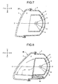
- Fig. 7 is a vertical cross-section of a vehicle lighting apparatus according to a second embodiment of the present invention.
- the parts in Fig. 7 that are identical to those in Fig. 1 through Fig. 6 are assigned the same reference numerals.
- the vehicle lighting apparatus 1A is a headlamp for driving and has a structure that is similar to the near-infrared projector 1 except that the filter 17 is absent.
- the vehicle lighting apparatus 1A when the filament 13 of the bulb 5 illuminates, the light reflected by the main reflective surface 7 produces a light distribution pattern required for driving, that is, a luminous light reaching far and covering a wide area. Further, the light reflected by the sub-reflective surface 8 produces a light distribution pattern further required for fast driving, that is, a highly luminous light reaching far at a level in alignment with the center of the vehicle (towards VU of the vertical axis VU-VD shown in Fig. 4).
- the luminous and wide light distribution pattern obtained from the light reflected by the main reflective surface 7 and the highly luminous light distribution pattern combine to form a substantially rectangular or elliptical low-beam distribution pattern HP as shown in Fig. 4, which is an ideal light distribution pattern required for driving.
- the vehicle lighting apparatus 1A according to the second embodiment realizes the effects substantially similar to those of the near-infrared projector 1.
- a vehicle may be fitted with both the vehicle lighting apparatus 1A according to the second embodiment to serve as a headlamp and the near-infrared projector 1.
- Fig. 8 is a vertical cross-section of a vehicle lighting apparatus according to a third embodiment of the present invention.
- the parts in Fig. 8 that are identical to those in Fig. 1 through Fig. 7 are assigned the same reference numerals.
- the vehicle lighting apparatus 1B has a structure that is similar to the near-infrared projector 1 except that the filter 17 in the vehicle lighting apparatus 1B is rotatable with the aid of a cylinder or a solenoid 18 to cover or uncover the opening of the reflector 6.
- the ideal near-infrared light distribution pattern IP substantially similar to that produced by the near-infrared projector 1 is obtained.
- the filament 13 of the bulb 5 illuminates in this state when the filter 17 swiveled back to uncover the opening of the reflector 6 by contracting the cylinder or the solenoid 18, as denoted by the chain double-dashed line in Fig. 8, the low-beam distribution pattern HP substantially similar to that produced by the vehicle lighting apparatus 1A according to the second embodiment is produced.
- the vehicle lighting apparatus 1B according to the third embodiment realizes the effects substantially similar to those of the near-infrared projector 1 and the vehicle lighting apparatus 1A.
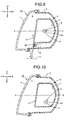
- Fig. 9 is a vertical cross-section of a vehicle lighting apparatus according to a fourth embodiment of the present invention.
- the parts in Fig. 9 that are identical to those in Fig. 1 through Fig. 8 are assigned the same reference numerals.
- the vehicle lighting apparatus 1C has a structure similar to the near-infrared projector 1 except that the filter 17 in the vehicle lighting apparatus 1C is slidable with the aid of a motor 19 and a rack-and-pinion mechanism 20 to cover or uncover the opening of the reflector 6.
- the ideal near-infrared light distribution pattern IP substantially similar to that produced by the near-infrared projector 1 is obtained.
- the filament 13 of the bulb 5 illuminates in the state when the filter 17 slid to uncover the opening of the reflector 6 with the aid of the rack-and-pinion mechanism 20 by the motor 19 driven in the reverse, as denoted by the chain double-dashed line in Fig. 9, the low-beam distribution pattern HP substantially similar to that produced by the vehicle lighting apparatus 1A according to the second embodiment is produced.
- the vehicle lighting apparatus 1C according to the fourth embodiment realizes the effects substantially similar to those of the near-infrared projector 1 and the vehicle lighting apparatus 1A.
- Fig. 10 is a vertical cross-section of a vehicle lighting apparatus according to a fifth embodiment of the present invention.
- the parts in Fig. 10 identical to those in Fig. 1 through Fig. 9 are assigned the same reference numerals.
- the vehicle lighting apparatus 1D according to the fifth embodiment has a structure according to any of the vehicle lighting apparatuses 1, 1A, 1B, and 1C according to first through fourth embodiments except that the bulb 5 is located below the optical axis Z-Z.
- the light reflected from that spot in the main reflective surface 7 which is closest to the filament 13 of the bulb 5 and which can potentially reflect the light most efficiently is not blocked by the bulb 5. Consequently, in the vehicle lighting apparatus, the light from the bulb 5 is more efficiently utilized.
- a C-8 type halogen lamp is used as the light source, that is, the bulb 5.
- Other types of light source such as a discharge lamp, like an HID bulb, may also be used.
- the light source that is the bulb 5
- the bulb 5 is fitted facing sideways from the left side with respect to the reflector 6.
- the bulb 5 may also be fitted facing sideways from the right side with respect to the reflector 6.
Landscapes
- Engineering & Computer Science (AREA)
- General Engineering & Computer Science (AREA)
- Physics & Mathematics (AREA)
- Spectroscopy & Molecular Physics (AREA)
- Non-Portable Lighting Devices Or Systems Thereof (AREA)
Abstract
Description
- The present document incorporates by reference the entire contents of Japanese priority document, 2004-193058 filed in Japan on June 30, 2004.
- The present invention relates to a vehicle lighting apparatus of a side-inserting bulb type, in which a bulb is fitted in a direction intersecting with an optical axis, and, more particularly, to a vehicle lighting apparatus by which an ideal light distribution pattern can be obtained from a near-infrared projector and a lamp for a low-beam distribution pattern, an the like.
- Conventionally, vehicle lighting apparatuses are of a longitudinal-inserting bulb type, in which the bulb is fitted in parallel to an optical axis, making a bulb axis parallel to the optical axis. However, in the conventional vehicle lighting apparatus, the insertion hole for the bulb is provided in a part of the reflective surface, which is closest to the bulb filament and which is a spot that can potentially reflect the light from the bulb most efficiently, thereby compromising the efficiency with which the light is reflected.
- In view of this drawback, vehicle lighting apparatuses were developed that allowed the bulb to be fitted facing sideways. One such vehicle lighting apparatus is disclosed in Japanese Patent Laid-Open Publication No. 2000-82305. The vehicle lighting apparatus disclosed in Japanese Patent Laid-Open Publication No. 2000-82305 (hereinafter, "conventional vehicle lighting apparatus") is described next. The conventional vehicle lighting apparatus includes a reflector plate and a reflective surface provided on the base. The reflector plate is provided with a bulb, a slot into which the bulb is inserted, and a lamp holder to which a mounting collar is detachably fitted. The reflective surface or a base member is attached to the reflector plate and directs the light from the lamp substantially parallel to as well in a predetermined direction with respect to the optical axis. In the conventional vehicle lighting apparatus, the direction of bulb insertion is at right angles with respect to the optical axis, disposing the lamp axis at right angles with respect to the optical axis.
- The functioning of the conventional vehicle lighting apparatus is explained next. When the lamp is turned on, the base member directs the light from the lamp substantially parallel to as well as in a predetermined direction with respect to the optical axis. The spot on the base member which is closest to the lamp filament and which can potentially reflect the light most efficiently is used for producing reflected light. Therefore, the reflective surface or the base member in the conventional vehicle lighting apparatus is more efficient than in the vehicle lighting apparatus in which the bulb is fitted vertically. Furthermore, the conventional vehicle lighting apparatus is more compact compared to the vehicle lighting apparatus with a longitudinal-inserting bulb.
- However, there are limitations to efficiently using the conventional vehicle lighting apparatus by having the light from the lamp reflected off the base member.
- It is an object of the present invention to at least solve the problems in the conventional technology.
- A vehicle lighting apparatus according to one aspect of the present invention includes a bulb having a front end and a rear end; a reflector including an insertion hole for inserting the front end and a mounting portion to which the rear end is detachably mounted; and a reflective surface that is provided on the reflector, and reflects light from the bulb in a predetermined direction. The bulb is inserted in a direction intersecting with an optical axis so that a bulb axis intersects with the optical axis on a substantially horizontal cross section. The bulb axis is inclined in such a manner that the front end is declined towards a direction of reflection of the light by the reflective surface with respect to the rear end.
- The above and other objects, features, advantages and technical and industrial significance of this invention will be better understood by reading the following detailed description of presently preferred embodiments of the invention, when considered in connection with the accompanying drawings.
-
- FIG. 1 is a vertical cross-section of a vehicle lighting apparatus according to a first embodiment of the present invention;
- FIG. 2 is a cross-section cut along the line II-II shown in Fig. 1;
- FIG. 3 is a view as seen from the line III-III shown in Fig. 1;
- FIG. 4 is a schematic for illustrating a reference luminous intensity distribution pattern, a near-infrared light distribution pattern, and a low-beam distribution pattern;
- FIG. 5 is a horizontal cross-section illustrating an effective part of reflective surfaces that reflect light emitted from a bulb;
- FIG. 6 is a horizontal cross-section illustrating the effective part of the reflective surfaces that reflect light emitted from the bulb in a conventional vehicle lighting apparatus;
- Fig. 7 is a vertical cross-section of a vehicle lighting apparatus according to a second embodiment of the present invention;
- Fig. 8 is a vertical cross-section of a vehicle lighting apparatus according to a third embodiment of the present invention;
- Fig. 9 is a vertical cross-section of a vehicle lighting apparatus according to a fourth embodiment of the present invention; and
- Fig. 10 is a vertical cross-section of a vehicle lighting apparatus according to a fifth embodiment of the present invention;
- Exemplary embodiments of a vehicle lighting apparatus according to the present invention are explained below with reference to the accompanying drawings. It should be noted that the present invention is not limited to the present embodiments. In the present specification and drawings, the reference symbol "F" denotes "front" of a vehicle, the reference symbol "B" denotes "rear" of the vehicle, the reference symbol "U" denotes "upper side" in a case where the driver faces the front, the reference symbol "D" denotes "lower side" in a case where the driver faces the front, the reference symbol "L" denotes "left side" in a case where the driver faces the front, and the reference symbol "R denotes "right side" in a case where the driver faces the front. The reference symbol "VU-VD" denotes "vertical axis", and the reference symbol "HL-HR" denotes "horizontal axis".
- A first embodiment of the vehicle lighting apparatus according to the present invention is explained next with reference to Fig. 1 through Fig. 5. The structure of the vehicle lighting apparatus according to the first embodiment is explained first.
- In Fig. 1 and Fig. 5, the
reference number 1 denotes the vehicle lighting apparatus according to the first embodiment, the vehicle lighting apparatus being a near-infrared projector (or a near-infrared lamp or a near-infrared headlamp). As shown in Fig. 1, the near-infrared projector 1 includes alamp housing 3 that sections off alamp compartment 2, a lamp lens (outer lens) 4, areflector 6 provided inside thelamp compartment 2, a light source in the form of abulb 5 mounted on thereflector 6,reflective surfaces reflector 6, and afilter 17 that lets infrared light get past. - The
bulb 5 is a C-8 type halogen bulb and includes aglass bulb 9 at the front end, an attachingflange 10 at the rear end, abase 11, aconnector 12, and afilament 13 provided within theglass bulb 9. The axis of theglass bulb 9 and the axis of thefilament 13 coincide with the axis ZB-ZB of thebulb 5. The front end of theglass bulb 9 of thebulb 5 is blacked out to form a blackenedtop 14. The blackenedtop 14 prevents the light emitted from the front end of thefilament 13 from scattering to the outside through theglass bulb 9. The prevention of scattering of the light emitted from the front end of thefilament 13 by the blackenedtop 14 does not adversely affect the overall light emitted by the near-infrared projector 1 because the amount of light emitted from the front end of thefilament 13 is negligible compared to the amount of light emitted from the sides of thefilament 13. - The
reflector 6 is mounted within thelamp housing 3 by means of a not shown optical axis adjusting mechanism. Thereflector 6 has aninsertion hole 15 into which theglass bulb 9 of thebulb 5 is inserted. The edge of theinsertion hole 15 of the reflector has abulb mounting portion 16 and a not shown mount mechanism on which the attachingflange 10 at the base of thebulb 5 detachably engages. - The
reflective surfaces reflective surface 7 and asub-reflective surface 8. The mainreflective surface 7 is a paraboloid of revolution non-uniform rational B-splines (NURBS) curved surface or a NURBS curved surface based on the paraboloid of revolution (see, for example, Japanese Patent Laid-Open Publication No. 2001-35215) F1, and asub-reflective surface 8, again, is a paraboloid of revolution NURBS curved surface or a NURBS curved surface based on the paraboloid of revolution F2. The optical axis Z-Z of the mainreflective surface 7 and the optical axis Z-Z of the sub-reflective surface coincide. The focal point F0 of the mainreflective surface 7 and the focal point F0 of thesub-reflective surface 8 coincide.
The mainreflective surface 7 and thesub-reflective surface 8 reflect the light emitted from thefilament 13 substantially parallel to as well as in a predetermined direction with respect to an optical axis Z-Z. The focal distance of thesub-reflective surface 8 is shorter than the focal distance of the mainreflective surface 7. The NURBS curved surfaces F1 and F2 are Non-Uniform Rational B-Spline Surface described in "Mathematical Elements for Computer Graphics" by David F. Rogers and J. Alan Adams. - The
filter 17 is provided covering the opening of thereflector 6 and includes a light transparent base and an infrared light permeable film. Thefilter 17 permits the infrared component of the light emitted from thefilament 13 of thebulb 5 of the halogen lamp to pass through while reflecting the visible component of the light. In other words, thefilter 17 is permeable to infrared light but impermeable to visible light. - In the near-
infrared projector 1, the bulb axis ZB-ZB is inclined at an angle with respect to the optical axis Z-Z in such a way that theglass bulb 9, which is the front end of thebulb 5, is oriented towards the direction of light reflection (towards the front F) by the mainreflective surface 7 and thesub-reflective surface 8 as compared to the rear end of the bulb that includes the attachingflange 10, thebase 11, and theconnector 12.
Thefilament 13 of thebulb 5 is located either at or close to the focal point F0 of the mainreflective surface 7 or the sub-reflective surface. Further, because the direction of insertion of thebulb 5 intersects the optical axis Z-Z, the bulb axis ZB-ZB intersects the optical axis Z-Z on a substantially horizontal cross section. - The near-
infrared projector 1 having the structure described above functions as a projector facilitating night vision. The near-infrared projector 1 is mounted in the front of a not shown vehicle along with a night vision imaging device meant for vehicles such as a charged-coupled-device (CC)D camera (not shown). The near-infrared projector 1 and the CCD camera together form a night vision device (a near-infrared night vision system for forward field of vision), which aids night driving. - When the
filament 13 of thebulb 5 illuminates, the light from thefilament 13 passes through all portions of theglass bulb 9 except from the blackenedtop 14 and the base portion, and gets reflected by the mainreflective surface 7 and thesub-reflective surface 8. The light is reflected substantially parallel to the optical axis Z-Z as well as in a predetermined direction by the mainreflective surface 7 and thesub-reflective surface 8. The reflected light then passes through thefilter 17 and then through thelamp lens 4 as transmitted light. The light through thelamp lens 4 produces a near-infrared light distribution pattern IP as shown in Fig. 4. The reflected light only has the infrared component as the visible component of the light is blocked by thefilter 17. Thus, an infrared night vision system can be realized by combining a CCD camera with the near-infrared projector 1 to aid night driving. - The light reflected by the main
reflective surface 7 produces a light distribution pattern required for a night vision device, that is, a luminous light reaching far and covering a wide area. The light reflected by thesub-reflective surface 8 produces a light distribution pattern further required for fast driving, that is, a highly luminous light reaching far at a level in alignment with the center of the vehicle (towards VU of the vertical axis VU-VD shown in Fig. 4). The luminous and wide light distribution pattern obtained from the light reflected by the mainreflective surface 7 and the highly luminous light distribution pattern obtained from the light reflected by thesub-reflective surface 8 combine to form a substantially rectangular near-infrared light distribution pattern IP with its long side along the horizontal axis HL-HR as shown in Fig. 4, which is an ideal light distribution pattern required on roads ranging from regular roads to highway fast lanes. - Fig. 5 is a schematic diagram of the vehicle lighting apparatus in the form of the near-
infrared projector 1 according to the first embodiment. Fig. 6 is a schematic diagram of a conventionalvehicle lighting apparatus 100. - As shown in Fig. 5, in the near-
infrared projector 1, the bulb axis ZB-ZB is inclined at an angle with respect to the optical axis Z-Z. On the other hand, as shown in Fig. 6, in the conventionalvehicle lighting apparatus 100, the bulb axis ZB-ZB is substantially orthogonal to the optical axis Z-Z. Thus, in the near-infrared projector 1, a solid angle θ1 formed by the light from thefilament 13 of thebulb 5 incident on the part of the mainreflective surface 7 that is closest to thefilament 13 and that reflects the light most efficiently is greater than a solid angle θ of the conventionalvehicle lighting apparatus 100. Furthermore, in the near-infrared projector 1, an area W1 on the mainreflective surface 7 up to the point where the light from thefilament 13 becomes incident is wider than the corresponding area in the conventionalvehicle lighting apparatus 100. In other words, a portion (the grid area A in Fig. 6) of the mainreflective surface 7, rendered unusable by the blackenedtop 14 of thebulb 5 in the conventionalvehicle lighting apparatus 100, can be effectively used in the near-infrared projector 1. As a result, in the near-infrared projector 1, the light from thebulb 5 is efficiently reflected by the mainreflective surface 7. - Particularly, in the near-
infrared projector 1, the bulb axis ZB-ZB is inclined at an angle with respect to the optical axis Z-Z in such a way that theglass bulb 9, which is the front end of thebulb 5, is oriented towards the direction of light reflection (towards the front F) by the mainreflective surface 7 and thesub-reflective surface 8 as compared to the rear end of the bulb that includes the attachingflange 10, thebase 11, and theconnector 12. Consequently, in the near-infrared projector 1, the area (the grid area B in Fig. 6) near thebulb mounting portion 16 of thereflector 6 rendered unusable in the conventionalvehicle lighting apparatus 100, is made available for providing an efficientsub-reflective surface 8. Thus, the near-infrared projector 1 can efficiently reflect the light from thebulb 5. - Thus, the near-
infrared projector 1 according to the first embodiment produces the near-infrared light distribution pattern IP as shown in Fig. 4, which is an ideal light distribution pattern obtained by combining the light reflected by the mainreflective surface 7 and thesub-reflective surface 8. As shown in Fig. 4, the area that is not illuminated by a reference luminous intensity distribution pattern LP, that is, the area above (in other words, further ahead of) a cut-off line CL of the reference luminous intensity distribution pattern LP, is illuminated by the near-infrared light distribution pattern IP. Therefore, the near-infrared light distribution pattern IP augments the illumination by the reference luminous intensity distribution pattern LP. - Further, in the near-
infrared projector 1, thebulb 5, which is a C-8 type halogen lamp and has a substantiallytubular glass bulb 9, and whose axis along with the axis of the similarly substantiallytubular filament 13 coincides with the bulb axis ZB-ZB, is fitted facing sideways in thereflector 6. Consequently, the filament axis (which coincides with the bulb axis ZB-ZB) and the optical axis Z-Z of the mainreflective surface 7 and thesub-reflective surface 8 are substantially orthogonal to each other on a substantially horizontal cross section. Thus, the near-infrared light distribution pattern IP, which is basically a magnification of the substantially rectangular (front elevation of the filament 13)filament 13, is produced by a simple structure. - Further, in the near-
infrared projector 1, a C-8 type halogen bulb is used as thebulb 5, which strikes a balance between bulb life and light distribution characteristics (the characteristic near-infrared light distribution pattern IP). Consequently, the near-infrared projector 1 is best suited as a vehicle night vision projection device which augments the reference luminous intensity distribution pattern LP of the headlamp. - Further, in the near-
infrared projector 1, the direction of bulb insertion intersects the optical axis Z-Z of thebulb 5 in a so-called side-inserting bulb type arrangement. Consequently, the size of the headlamp can be reduced in the optical axis Z-Z, making it ideal as a near-infrared projector. - Fig. 7 is a vertical cross-section of a vehicle lighting apparatus according to a second embodiment of the present invention. The parts in Fig. 7 that are identical to those in Fig. 1 through Fig. 6 are assigned the same reference numerals.
- The
vehicle lighting apparatus 1A according to the second embodiment is a headlamp for driving and has a structure that is similar to the near-infrared projector 1 except that thefilter 17 is absent. - Because of the way the
vehicle lighting apparatus 1A according to the second embodiment is constructed, when thefilament 13 of thebulb 5 illuminates, the light reflected by the mainreflective surface 7 produces a light distribution pattern required for driving, that is, a luminous light reaching far and covering a wide area. Further, the light reflected by thesub-reflective surface 8 produces a light distribution pattern further required for fast driving, that is, a highly luminous light reaching far at a level in alignment with the center of the vehicle (towards VU of the vertical axis VU-VD shown in Fig. 4). The luminous and wide light distribution pattern obtained from the light reflected by the mainreflective surface 7 and the highly luminous light distribution pattern combine to form a substantially rectangular or elliptical low-beam distribution pattern HP as shown in Fig. 4, which is an ideal light distribution pattern required for driving. - Thus, the
vehicle lighting apparatus 1A according to the second embodiment realizes the effects substantially similar to those of the near-infrared projector 1. - A vehicle may be fitted with both the
vehicle lighting apparatus 1A according to the second embodiment to serve as a headlamp and the near-infrared projector 1. - Fig. 8 is a vertical cross-section of a vehicle lighting apparatus according to a third embodiment of the present invention. The parts in Fig. 8 that are identical to those in Fig. 1 through Fig. 7 are assigned the same reference numerals.
- The
vehicle lighting apparatus 1B according to the third embodiment has a structure that is similar to the near-infrared projector 1 except that thefilter 17 in thevehicle lighting apparatus 1B is rotatable with the aid of a cylinder or asolenoid 18 to cover or uncover the opening of thereflector 6. - Because of the way the
vehicle lighting apparatus 1B according to the third embodiment is constructed, when thefilament 13 of thebulb 5 illuminates in the state when thefilter 17 is swiveled to close the opening of thereflector 6 by extending the cylinder or thesolenoid 18, the ideal near-infrared light distribution pattern IP substantially similar to that produced by the near-infrared projector 1 is obtained. When thefilament 13 of thebulb 5 illuminates in this state when thefilter 17 swiveled back to uncover the opening of thereflector 6 by contracting the cylinder or thesolenoid 18, as denoted by the chain double-dashed line in Fig. 8, the low-beam distribution pattern HP substantially similar to that produced by thevehicle lighting apparatus 1A according to the second embodiment is produced. - Thus, the
vehicle lighting apparatus 1B according to the third embodiment realizes the effects substantially similar to those of the near-infrared projector 1 and thevehicle lighting apparatus 1A. - Fig. 9 is a vertical cross-section of a vehicle lighting apparatus according to a fourth embodiment of the present invention. The parts in Fig. 9 that are identical to those in Fig. 1 through Fig. 8 are assigned the same reference numerals.
- The
vehicle lighting apparatus 1C according to the fourth embodiment has a structure similar to the near-infrared projector 1 except that thefilter 17 in thevehicle lighting apparatus 1C is slidable with the aid of amotor 19 and a rack-and-pinion mechanism 20 to cover or uncover the opening of thereflector 6. - Because of the way the
vehicle lighting apparatus 1C according to the fourth embodiment is constructed, when thefilament 13 of thebulb 5 illuminates in the state when thefilter 17 is slid to close the opening of thereflector 6 by with the aid of the rack-andpinion mechanism 20 driven by themotor 19, the ideal near-infrared light distribution pattern IP substantially similar to that produced by the near-infrared projector 1 is obtained. When thefilament 13 of thebulb 5 illuminates in the state when thefilter 17 slid to uncover the opening of thereflector 6 with the aid of the rack-and-pinion mechanism 20 by themotor 19 driven in the reverse, as denoted by the chain double-dashed line in Fig. 9, the low-beam distribution pattern HP substantially similar to that produced by thevehicle lighting apparatus 1A according to the second embodiment is produced. - Thus, the
vehicle lighting apparatus 1C according to the fourth embodiment realizes the effects substantially similar to those of the near-infrared projector 1 and thevehicle lighting apparatus 1A. - Fig. 10 is a vertical cross-section of a vehicle lighting apparatus according to a fifth embodiment of the present invention. The parts in Fig. 10 identical to those in Fig. 1 through Fig. 9 are assigned the same reference numerals.
- The
vehicle lighting apparatus 1D according to the fifth embodiment has a structure according to any of thevehicle lighting apparatuses bulb 5 is located below the optical axis Z-Z. - Because of the way the
vehicle lighting apparatus 1D according to the fifth embodiment is constructed, the light reflected from that spot in the mainreflective surface 7 which is closest to thefilament 13 of thebulb 5 and which can potentially reflect the light most efficiently is not blocked by thebulb 5. Consequently, in the vehicle lighting apparatus, the light from thebulb 5 is more efficiently utilized. - According to the present invention, a C-8 type halogen lamp is used as the light source, that is, the
bulb 5. Other types of light source such as a discharge lamp, like an HID bulb, may also be used. - Furthermore, according to the present invention, the light source, that is the
bulb 5, is fitted facing sideways from the left side with respect to thereflector 6. Thebulb 5 may also be fitted facing sideways from the right side with respect to thereflector 6. - Although the invention has been described with respect to a specific embodiment for a complete and clear disclosure, the appended claims are not to be thus limited but are to be construed as embodying all modifications and alternative constructions that may occur to one skilled in the art that fairly fall within the basic teaching herein set forth.
Claims (6)
- A vehicle lighting apparatus comprising:a bulb (5) having a front end (9) and a rear end (10);a reflector (6) including
an insertion hole (15) for inserting the front end (9); and
a mounting portion (16) to which the rear end (10) is detachably mounted; anda reflective surface (7, 8) that is provided on the reflector (6), and reflects light from the bulb (5) in a predetermined direction, whereinthe bulb (5) is inserted in a direction intersecting with an optical axis so that a bulb axis intersects with the optical axis on a substantially horizontal cross section, andthe bulb axis is inclined in such a manner that the front end (9) is declined towards a direction of reflection of the light by the reflective surface with respect to the rear end (10). - The vehicle lighting apparatus according to claim 1, wherein the reflective surface (7, 8) includes
a main reflective surface (7) that is formed with a paraboloid of revolution or a non-uniform rational B-splines curved surface with a first focal distance; and
a sub-reflective surface (8) that is disposed around the mounting portion (16), and is formed with a paraboloid of revolution or a non-uniform rational B-splines curved surface with a second focal distance that is shorter than the first focal distance. - The vehicle lighting apparatus according to claim 1 or 2, wherein the bulb (5) is a C-8 type halogen lamp consisting of a glass bulb (9) with a blackened top portion (14).
- The vehicle lighting apparatus according to any one of claims 1 to 3, further comprising a filter (17) that reflects visible light component and passes infrared light component from the light reflected by the reflective surface (7, 8).
- The vehicle lighting apparatus according to any one of claims 1 to 3, further comprising a filter (17) that reflects visible light component and passes infrared light component from the light reflected by the reflective surface (7, 8), wherein
the filter (17) is openably and closably provided on an optical path of the light reflected, and
closing of the filter (17) obtains infrared light, and opening of the filter (17) obtains visible light. - The vehicle lighting apparatus according to any one of claims 1 to 5, wherein the bulb (5) is disposed below the optical axis.
Applications Claiming Priority (1)
| Application Number | Priority Date | Filing Date | Title |
|---|---|---|---|
| JP2004193058A JP2006019049A (en) | 2004-06-30 | 2004-06-30 | Vehicle lighting |
Publications (3)
| Publication Number | Publication Date |
|---|---|
| EP1612472A2 true EP1612472A2 (en) | 2006-01-04 |
| EP1612472A3 EP1612472A3 (en) | 2007-03-14 |
| EP1612472B1 EP1612472B1 (en) | 2008-05-28 |
Family
ID=35079309
Family Applications (1)
| Application Number | Title | Priority Date | Filing Date |
|---|---|---|---|
| EP05013959A Expired - Lifetime EP1612472B1 (en) | 2004-06-30 | 2005-06-28 | Vehicle lighting apparatus |
Country Status (4)
| Country | Link |
|---|---|
| US (1) | US20060002128A1 (en) |
| EP (1) | EP1612472B1 (en) |
| JP (1) | JP2006019049A (en) |
| DE (1) | DE602005007109D1 (en) |
Cited By (1)
| Publication number | Priority date | Publication date | Assignee | Title |
|---|---|---|---|---|
| DE202012004090U1 (en) | 2012-04-24 | 2012-05-31 | Automotive Lighting Reutlingen Gmbh | Bulb holder and motor vehicle headlight with such a bulb holder |
Families Citing this family (10)
| Publication number | Priority date | Publication date | Assignee | Title |
|---|---|---|---|---|
| JP4714107B2 (en) * | 2006-08-09 | 2011-06-29 | 株式会社小糸製作所 | Infrared light irradiation lamp for vehicles |
| JP4714108B2 (en) * | 2006-08-09 | 2011-06-29 | 株式会社小糸製作所 | Infrared light irradiation lamp for vehicles |
| JP2008041571A (en) * | 2006-08-09 | 2008-02-21 | Koito Mfg Co Ltd | Infrared light irradiation lamp for vehicles |
| US20090052200A1 (en) * | 2007-08-22 | 2009-02-26 | Thomas Tessnow | Single source visible and IR vehicle headlamp |
| US20090206260A1 (en) * | 2008-02-04 | 2009-08-20 | Brandon Hite | Night vision technology: broad band imaging |
| CN101660666B (en) * | 2008-11-28 | 2010-12-15 | 海洋王照明科技股份有限公司 | Portable lamps |
| US8905609B2 (en) | 2010-09-30 | 2014-12-09 | Osram Sylvania Inc. | Lighting system with shutter, reflector, primary light engine and a secondary light engine coupled to shutter |
| JP6042638B2 (en) * | 2012-06-12 | 2016-12-14 | スタンレー電気株式会社 | Near-infrared projector |
| KR102128220B1 (en) * | 2020-04-23 | 2020-06-29 | 주식회사 레젠 | Dual reflector adjusting module for LED lamp and lighting lamp implement using of the same |
| KR20240033940A (en) * | 2022-09-06 | 2024-03-13 | 현대자동차주식회사 | Infrared lamp apparatus and system for mobility |
Family Cites Families (40)
| Publication number | Priority date | Publication date | Assignee | Title |
|---|---|---|---|---|
| US1136507A (en) * | 1914-10-16 | 1915-04-20 | Emerson L Clark | Headlight. |
| DE511572C (en) * | 1925-03-06 | 1930-11-15 | Martha Wood Caughlan Geb Wood | Headlights |
| GB2000266B (en) * | 1977-06-17 | 1982-01-27 | Lucas Industries Ltd | Lamp reflector for a motor vehicle |
| FR2460442A1 (en) * | 1979-06-29 | 1981-01-23 | Cibie Projecteurs | NEW PROJECTOR STRUCTURE, IN PARTICULAR OF AUTOMOTIVE PROJECTOR |
| GB8328308D0 (en) * | 1983-10-22 | 1983-11-23 | Lucas Ind Plc | Lamp |
| US4731714A (en) * | 1984-04-18 | 1988-03-15 | Cooper Industries | Luminaire |
| US4947303A (en) * | 1986-05-19 | 1990-08-07 | Musco Corporation | Glare control lamp and reflector assembly and method for glare control |
| FR2580782B1 (en) * | 1985-04-22 | 1987-07-10 | Cibie Projecteurs | ROAD PROJECTOR FOR A MOTOR VEHICLE INCORPORATING AN ELLIPTICAL REFLECTOR AND A PARABOLIC REFLECTOR |
| DE8523724U1 (en) * | 1985-08-17 | 1985-10-10 | Westfälische Metall Industrie KG Hueck & Co, 4780 Lippstadt | Dipped vehicle headlight with an ellipsoidal reflector |
| JPS63111704U (en) * | 1987-01-14 | 1988-07-18 | ||
| JPH01120702A (en) * | 1987-11-05 | 1989-05-12 | Koito Mfg Co Ltd | Vehicle head light |
| JPH0658761B2 (en) * | 1988-11-08 | 1994-08-03 | 株式会社小糸製作所 | Headlight reflector |
| US4994947A (en) * | 1989-11-20 | 1991-02-19 | Ford Motor Company | Reflector and lighting fixture comprising same |
| DE4002576C5 (en) * | 1990-01-30 | 2005-06-02 | Automotive Lighting Reutlingen Gmbh | Headlamp with dipped and main beam for motor vehicles |
| US5264993A (en) * | 1990-01-30 | 1993-11-23 | Robert Bosch Gmbh | Headlamp for power vehicles |
| JPH0716247Y2 (en) * | 1990-04-20 | 1995-04-12 | スタンレー電気株式会社 | head lamp |
| US5303126A (en) * | 1991-11-26 | 1994-04-12 | Stanley Electric Co., Ltd. | Headlight for irradiating light beam for a vehicle passing by in the opposite direction |
| JP2575236Y2 (en) * | 1992-06-12 | 1998-06-25 | スタンレー電気株式会社 | Projector lamp |
| JP2605483Y2 (en) * | 1993-12-20 | 2000-07-17 | 株式会社小糸製作所 | Vehicle lighting |
| JP2989098B2 (en) * | 1994-04-25 | 1999-12-13 | 株式会社小糸製作所 | VEHICLE LIGHTING, ITS MANUFACTURING APPARATUS AND MANUFACTURING METHOD |
| US5676455A (en) * | 1995-11-01 | 1997-10-14 | Spi Lighting, Inc. | Wall mountable lighting fixture |
| JP3129643B2 (en) * | 1995-12-08 | 2001-01-31 | 株式会社小糸製作所 | Vehicle headlights |
| EP0854316B1 (en) * | 1997-01-17 | 2005-04-27 | Stanley Electric Co., Ltd. | Projector type lamp |
| JP3280885B2 (en) * | 1997-05-20 | 2002-05-13 | 株式会社小糸製作所 | Vehicle lighting |
| JPH11149804A (en) * | 1997-11-14 | 1999-06-02 | Stanley Electric Co Ltd | head lamp |
| DE19750494B4 (en) * | 1997-11-14 | 2009-07-30 | Automotive Lighting Reutlingen Gmbh | Method of making high beam headlamps for vehicles |
| JP3005687B2 (en) * | 1998-05-28 | 2000-01-31 | スタンレー電気株式会社 | Lamp |
| FR2783038B1 (en) * | 1998-09-04 | 2000-12-01 | Valeo Vision | MOTOR VEHICLE PROJECTOR WITH TRANSVERSE LAMP, EQUIPPED WITH IMPROVED LAMP MOUNTING MEANS |
| JP4285716B2 (en) * | 1999-03-26 | 2009-06-24 | 株式会社小糸製作所 | Vehicle headlamp device |
| JP3920052B2 (en) * | 2001-07-06 | 2007-05-30 | 株式会社小糸製作所 | Infrared irradiation lamp for automobiles |
| FR2830073B1 (en) * | 2001-09-27 | 2003-12-12 | Valeo Vision | ELLIPTICAL LIGHTING PROJECTOR FOR A MOTOR VEHICLE COMPRISING A SECONDARY OPTICAL SYSTEM |
| JP4089866B2 (en) * | 2001-10-12 | 2008-05-28 | スタンレー電気株式会社 | Light projecting unit and LED vehicle illumination lamp comprising the light projecting unit |
| FR2839138B1 (en) * | 2002-04-30 | 2005-01-07 | Valeo Vision | BIFUNCTION PROJECTOR DEVICE FOR A MOTOR VEHICLE |
| JP4034152B2 (en) * | 2002-09-10 | 2008-01-16 | 株式会社小糸製作所 | Vehicle lighting |
| JP4379673B2 (en) * | 2002-10-07 | 2009-12-09 | 株式会社小糸製作所 | Vehicle headlamp |
| JP2004134100A (en) * | 2002-10-08 | 2004-04-30 | Toshiba Lighting & Technology Corp | Metal vapor discharge lamps, floodlights, vehicle headlamps and metal vapor discharge lamp lighting devices |
| JP4335621B2 (en) * | 2003-04-25 | 2009-09-30 | スタンレー電気株式会社 | Vehicle lighting |
| FR2854941B1 (en) * | 2003-05-16 | 2006-01-20 | Valeo Vision | PROJECTOR DEVICE WITH PIVOTING PLATE, IN PARTICULAR FOR A MOTOR VEHICLE |
| ES2314350T3 (en) * | 2003-06-27 | 2009-03-16 | Valeo Vision | PROJECTOR FOR AUTOMOBILE VEHICLE PROVIDED WITH A REFLECTOR AND AN OPTICAL DEVIATION ELEMENT. |
| JP2005166371A (en) * | 2003-12-01 | 2005-06-23 | Ichikoh Ind Ltd | Vehicle lighting |
-
2004
- 2004-06-30 JP JP2004193058A patent/JP2006019049A/en active Pending
-
2005
- 2005-06-28 EP EP05013959A patent/EP1612472B1/en not_active Expired - Lifetime
- 2005-06-28 DE DE602005007109T patent/DE602005007109D1/en not_active Expired - Lifetime
- 2005-06-30 US US11/170,072 patent/US20060002128A1/en not_active Abandoned
Cited By (2)
| Publication number | Priority date | Publication date | Assignee | Title |
|---|---|---|---|---|
| DE202012004090U1 (en) | 2012-04-24 | 2012-05-31 | Automotive Lighting Reutlingen Gmbh | Bulb holder and motor vehicle headlight with such a bulb holder |
| EP2657592A2 (en) | 2012-04-24 | 2013-10-30 | Automotive Lighting Reutlingen GmbH | Lamp holder and motor vehicle headlamp with such a lamp holder |
Also Published As
| Publication number | Publication date |
|---|---|
| US20060002128A1 (en) | 2006-01-05 |
| DE602005007109D1 (en) | 2008-07-10 |
| EP1612472A3 (en) | 2007-03-14 |
| JP2006019049A (en) | 2006-01-19 |
| EP1612472B1 (en) | 2008-05-28 |
Similar Documents
| Publication | Publication Date | Title |
|---|---|---|
| CN102213389B (en) | Headlight for automobile | |
| CN103443534B (en) | Motor vehicle headlight with multifunctional projection module | |
| CN101776238B (en) | Vehicle lighting device | |
| CN101793372B (en) | Vehicle headlamp | |
| CN100394101C (en) | Vehicle Headlamps | |
| CN101761847B (en) | Vehicle headlamp | |
| JP5468754B2 (en) | Projection module for automobile headlights | |
| CN101725879B (en) | Vehicle headlamp | |
| CN101769493A (en) | Vehicle Headlamps | |
| CN106838758A (en) | Headlamp and moving body | |
| EP2360426A2 (en) | Vehicular illumination lamp | |
| CN101225933B (en) | Vehicle Headlamps | |
| EP1612472B1 (en) | Vehicle lighting apparatus | |
| JP2626199B2 (en) | Vehicle discharge lamp headlamp | |
| CN101122374A (en) | Infrared Irradiation Lamps for Vehicles | |
| CN119452205A (en) | Vehicle lighting | |
| US7661861B2 (en) | Vehicle headlamp | |
| US7175322B2 (en) | Vehicle headlamp | |
| JP2009104790A (en) | Vehicle headlamp | |
| JP2007323839A (en) | Vehicle lighting | |
| JP4453495B2 (en) | Vehicle lighting | |
| CN101566297B (en) | Lamp fitting for vehicle | |
| JP2001093311A (en) | Headlamp for night vision device | |
| JP2008276955A (en) | Vehicle headlamp | |
| CN110553221B (en) | Cut-off lighting module with multi-zone reflector |
Legal Events
| Date | Code | Title | Description |
|---|---|---|---|
| PUAI | Public reference made under article 153(3) epc to a published international application that has entered the european phase |
Free format text: ORIGINAL CODE: 0009012 |
|
| AK | Designated contracting states |
Kind code of ref document: A2 Designated state(s): AT BE BG CH CY CZ DE DK EE ES FI FR GB GR HU IE IS IT LI LT LU MC NL PL PT RO SE SI SK TR |
|
| AX | Request for extension of the european patent |
Extension state: AL BA HR LV MK YU |
|
| PUAL | Search report despatched |
Free format text: ORIGINAL CODE: 0009013 |
|
| AK | Designated contracting states |
Kind code of ref document: A3 Designated state(s): AT BE BG CH CY CZ DE DK EE ES FI FR GB GR HU IE IS IT LI LT LU MC NL PL PT RO SE SI SK TR |
|
| AX | Request for extension of the european patent |
Extension state: AL BA HR LV MK YU |
|
| 17P | Request for examination filed |
Effective date: 20070228 |
|
| 17Q | First examination report despatched |
Effective date: 20070430 |
|
| AKX | Designation fees paid |
Designated state(s): DE FR GB |
|
| GRAP | Despatch of communication of intention to grant a patent |
Free format text: ORIGINAL CODE: EPIDOSNIGR1 |
|
| RIN1 | Information on inventor provided before grant (corrected) |
Inventor name: SUZUKI, EIJIC/O ICHIKOH INDUSTRIES, LTD. Inventor name: OHKUBO, YASUHIROC/O ICHIKOH INDUSTRIES, LTD. |
|
| GRAS | Grant fee paid |
Free format text: ORIGINAL CODE: EPIDOSNIGR3 |
|
| GRAA | (expected) grant |
Free format text: ORIGINAL CODE: 0009210 |
|
| AK | Designated contracting states |
Kind code of ref document: B1 Designated state(s): DE FR GB |
|
| REG | Reference to a national code |
Ref country code: GB Ref legal event code: FG4D |
|
| REF | Corresponds to: |
Ref document number: 602005007109 Country of ref document: DE Date of ref document: 20080710 Kind code of ref document: P |
|
| PLBE | No opposition filed within time limit |
Free format text: ORIGINAL CODE: 0009261 |
|
| STAA | Information on the status of an ep patent application or granted ep patent |
Free format text: STATUS: NO OPPOSITION FILED WITHIN TIME LIMIT |
|
| 26N | No opposition filed |
Effective date: 20090303 |
|
| PGFP | Annual fee paid to national office [announced via postgrant information from national office to epo] |
Ref country code: DE Payment date: 20120620 Year of fee payment: 8 |
|
| PGFP | Annual fee paid to national office [announced via postgrant information from national office to epo] |
Ref country code: FR Payment date: 20120619 Year of fee payment: 8 Ref country code: GB Payment date: 20120627 Year of fee payment: 8 |
|
| GBPC | Gb: european patent ceased through non-payment of renewal fee |
Effective date: 20130628 |
|
| REG | Reference to a national code |
Ref country code: DE Ref legal event code: R119 Ref document number: 602005007109 Country of ref document: DE Effective date: 20140101 |
|
| REG | Reference to a national code |
Ref country code: FR Ref legal event code: ST Effective date: 20140228 |
|
| PG25 | Lapsed in a contracting state [announced via postgrant information from national office to epo] |
Ref country code: DE Free format text: LAPSE BECAUSE OF NON-PAYMENT OF DUE FEES Effective date: 20140101 Ref country code: GB Free format text: LAPSE BECAUSE OF NON-PAYMENT OF DUE FEES Effective date: 20130628 |
|
| PG25 | Lapsed in a contracting state [announced via postgrant information from national office to epo] |
Ref country code: FR Free format text: LAPSE BECAUSE OF NON-PAYMENT OF DUE FEES Effective date: 20130701 |