EP1612397A2 - Diesel fuel filter - Google Patents
Diesel fuel filter Download PDFInfo
- Publication number
- EP1612397A2 EP1612397A2 EP05253656A EP05253656A EP1612397A2 EP 1612397 A2 EP1612397 A2 EP 1612397A2 EP 05253656 A EP05253656 A EP 05253656A EP 05253656 A EP05253656 A EP 05253656A EP 1612397 A2 EP1612397 A2 EP 1612397A2
- Authority
- EP
- European Patent Office
- Prior art keywords
- fuel
- recirculation
- passage
- valve
- filter
- Prior art date
- Legal status (The legal status is an assumption and is not a legal conclusion. Google has not performed a legal analysis and makes no representation as to the accuracy of the status listed.)
- Withdrawn
Links
- 239000002283 diesel fuel Substances 0.000 title claims abstract description 47
- 239000000446 fuel Substances 0.000 claims abstract description 279
- 239000002828 fuel tank Substances 0.000 claims description 19
- 238000002347 injection Methods 0.000 claims description 16
- 239000007924 injection Substances 0.000 claims description 16
- 230000008018 melting Effects 0.000 claims description 14
- 238000002844 melting Methods 0.000 claims description 14
- 238000011144 upstream manufacturing Methods 0.000 claims description 7
- 230000003134 recirculating effect Effects 0.000 claims description 4
- 238000005086 pumping Methods 0.000 description 5
- 239000000126 substance Substances 0.000 description 3
- XLYOFNOQVPJJNP-UHFFFAOYSA-N water Substances O XLYOFNOQVPJJNP-UHFFFAOYSA-N 0.000 description 3
- 238000010586 diagram Methods 0.000 description 2
- 238000001914 filtration Methods 0.000 description 2
- 238000010792 warming Methods 0.000 description 1
Images


Classifications
-
- B—PERFORMING OPERATIONS; TRANSPORTING
- B01—PHYSICAL OR CHEMICAL PROCESSES OR APPARATUS IN GENERAL
- B01D—SEPARATION
- B01D36/00—Filter circuits or combinations of filters with other separating devices
- B01D36/003—Filters in combination with devices for the removal of liquids
-
- F—MECHANICAL ENGINEERING; LIGHTING; HEATING; WEAPONS; BLASTING
- F02—COMBUSTION ENGINES; HOT-GAS OR COMBUSTION-PRODUCT ENGINE PLANTS
- F02M—SUPPLYING COMBUSTION ENGINES IN GENERAL WITH COMBUSTIBLE MIXTURES OR CONSTITUENTS THEREOF
- F02M37/00—Apparatus or systems for feeding liquid fuel from storage containers to carburettors or fuel-injection apparatus; Arrangements for purifying liquid fuel specially adapted for, or arranged on, internal-combustion engines
- F02M37/22—Arrangements for purifying liquid fuel specially adapted for, or arranged on, internal-combustion engines, e.g. arrangements in the feeding system
- F02M37/24—Arrangements for purifying liquid fuel specially adapted for, or arranged on, internal-combustion engines, e.g. arrangements in the feeding system characterised by water separating means
- F02M37/26—Arrangements for purifying liquid fuel specially adapted for, or arranged on, internal-combustion engines, e.g. arrangements in the feeding system characterised by water separating means with water detection means
-
- F—MECHANICAL ENGINEERING; LIGHTING; HEATING; WEAPONS; BLASTING
- F02—COMBUSTION ENGINES; HOT-GAS OR COMBUSTION-PRODUCT ENGINE PLANTS
- F02M—SUPPLYING COMBUSTION ENGINES IN GENERAL WITH COMBUSTIBLE MIXTURES OR CONSTITUENTS THEREOF
- F02M37/00—Apparatus or systems for feeding liquid fuel from storage containers to carburettors or fuel-injection apparatus; Arrangements for purifying liquid fuel specially adapted for, or arranged on, internal-combustion engines
- F02M37/22—Arrangements for purifying liquid fuel specially adapted for, or arranged on, internal-combustion engines, e.g. arrangements in the feeding system
- F02M37/32—Arrangements for purifying liquid fuel specially adapted for, or arranged on, internal-combustion engines, e.g. arrangements in the feeding system characterised by filters or filter arrangements
Definitions
- the present invention relates to a diesel fuel filter (a fuel filter for a diesel engine). More particularly, the present invention relates to a diesel fuel filter which can prevent blockage of a fuel filter element due to a fuel wax.
- Japanese Patent Publication No. 2002-256995 discloses a diesel fuel passage including a diesel fuel filter as illustrated in FIG. 7.
- the diesel fuel passage includes a fuel supply passage 3 for use in supplying fuel from a fuel tank 1 to a fuel injection pump 2, a fuel return passage 4 for use in returning fuel from the fuel injection pump 2 to the fuel tank 1, and a fuel recirculation passage 5 for use in recirculating the fuel from the fuel return passage 4 to the fuel supply passage 3.
- a fuel pumping pump 6 and a fuel filter 7 for use in filtering foreign substances contained in fuel are provided in the fuel recirculation passage 5.
- a recirculation valve 8 and a one-way valve 9 are disposed in an order of the recirculation valve 8 and the one-way valve 9 in a direction of flow of recirculation fuel.
- Japanese Patent Publication No. 2003-293884 discloses a fuel filter 7 as illustrated in FIG. 6.
- the fuel filter 7 includes a housing 10 in which a filter element 11, at least a portion of a fuel recirculation passage 5, a recirculation valve 8 and a one-way valve 9 are provided in that order.
- a passage of flow of the fuel is the same as that of FIG 7.
- the recirculation valve 8 of a bimetal-type detects a fuel temperature and opens when the fuel temperature is relatively low so that a warmed fuel flowing through the fuel return passage 4 is recirculated to the fuel supply passage 3.
- the temperature of the fuel flowing in the fuel supply passage 3 is raised, so that a wax which has been captured by a filter element 11 is melted and blockage of the filter element 11 due to the wax is prevented.
- the recirculation valve 8 is closed, so that an entire amount of the fuel flowing in the fuel return passage 4 returns to the fuel tank 1. While these are repeated, a temperature of the fuel system rises and becomes stable and the recirculation valve 8 is closed whereby warming of the supply fuel by the return fuel is off.
- the recirculation valve 8 since the recirculation valve 8 communicates with the warmed fuel in the fuel return passage 4, the recirculation valve 8 is unlikely to be open. Accordingly, opening and closing of the recirculation valve 8 cannot follow a change of the temperature of the fuel in the fuel filter 7 with a good response. As a result, after the recirculation valve 8 is closed, the filter element 11 is blocked by a wax, and a negative pressure of the filter at an outlet of the filter is increased (causing a high negative pressure as illustrated by characteristic A in FIG. 5), so that running of the vehicle becomes unstable.
- An object of the invention is to provide a diesel fuel filter which can prevent blockage of a filter element by a fuel wax when a temperature of fuel is low.
- the recirculation valve and the one-way valve are arranged in the order of the one-way valve and the recirculation valve in the direction of flow of recirculation fuel, the recirculation valve is located downstream of the one-way valve (i.e., on the side closer to the fuel supply passage), so that the recirculation valve can always contact the fuel (i.e., the supply-side fuel) in the diesel fuel filter even after the recirculation valve is closed, and the recirculation valve can follow a change of a temperature of the supply-side fuel with a good response.
- the recirculation valve opens in a short time period detecting the fuel temperature, thereby allowing the recirculation fuel to flow through the fuel recirculation passage and raising the temperature of the supply-side fuel to melt the wax in the fuel and to prevent blockage of the filter element by the wax.
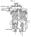
- FIGs. 1 and 2 illustrate a diesel fuel filter according to a first embodiment of the invention
- FIG 3 illustrates a diesel fuel filter according to a second embodiment of the invention
- FIG 4 illustrates a fuel passage including the diesel fuel filter according to the present invention.
- a diesel fuel filter 7 according to the present invention is provided in a fuel passage 12.
- the fuel passage 12 includes a fuel supply passage 3 for use in supplying fuel (diesel fuel) from a fuel tank 1 to a fuel injection pump 2, a fuel return passage 4 for use in returning the fuel from the fuel injection pump 2 to the fuel tank 1, and a fuel recirculation passage 5 for use in recirculating the fuel from the fuel return passage 4 to the fuel supply passage 3.
- a fuel pumping pump 6 and a filter element 11 of the fuel filter 7 for use in filtering foreign substances contained in fuel are provided.
- the fuel recirculation passage 5 allows fuel to be recirculated therethrough from the fuel return passage 4 to a portion of the fuel supply passage 3 between the fuel pumping pump 6 and the filter element 11 of the fuel filter 7 (a converging point 15).
- a direction of flow of the supplied fuel flowing in the fuel supply passage 3 is a direction from the fuel tank 1 to the fuel injection pump 2
- a direction of flow of the returned fuel flowing in the fuel return passage 4 is a direction from the fuel injection pump 2 to the fuel tank 1.
- a direction of flow of the recirculation fuel flowing in the fuel recirculation passage 5 is a direction from the fuel return passage 4 to the fuel supply passage 3.
- a recirculation valve 8 and a one-way valve 9 are disposed.
- the diesel fuel filter 7 includes at least a portion of the fuel recirculation passage 5.
- the recirculation valve 8 and the one-way valve 9 are disposed in an order of the recirculation valve 8 and the one-way valve 9 in the direction of flow of recirculation fuel.
- the disposition order of the recirculation valve 8 and the one-way valve 9 in the direction of flow of recirculation fuel of the present invention is reverse to the disposition order of the one-way valve 9 and the recirculation valve 8 in the direction of flow of recirculation fuel of the conventional diesel fuel filter.
- the diesel filter 7 further includes at least a portion of the fuel supply passage 3 for use in supplying the fuel from the fuel tank 1 to the fuel injection pump 2.
- a downstream end of the fuel recirculation passage 5 in the direction of flow of the recirculation fuel communicates with the at least a portion of the fuel supply passage 3.
- An upstream end of the fuel recirculation passage 5 in the direction of flow of the recirculation fuel communicates with the fuel return passage 4 from the fuel injection pump 2 to the fuel tank 1.
- the diesel fuel filter 7 further includes a housing 10, the filter element 11 disposed within the housing 10, and a space 16 formed in the housing 10 and below the filter element 11.
- the at least a portion of the fuel recirculation passage 5 is disposed in the space 16.
- the downstream end of the fuel recirculation passage 5 in the direction of flow of the recirculation fuel communicates with a portion between the fuel pumping pump 6 and the filter element 11 of the fuel supply passage 3 at the converging point 15 in the space 16.
- a passage wall of the fuel recirculation passage 5 is disposed, and in the passage wall, the recirculation valve 8 and the one-way valve 9 are disposed.
- the recirculation valve 8 is a valve which opens when a temperature of the fuel flowing in the fuel supply passage 3 is equal to or lower than a wax melting temperature, and which is closed when the temperature of the fuel flowing in the fuel supply passage 3 is higher than the wax melting temperature.
- the recirculation valve 8 allows a portion of the warmed fuel to be recirculated through the fuel recirculation passage 5 to the fuel supply passage 3 and to be mixed with the supply fuel of a low temperature thereby raising the temperature of the supply fuel at a portion of the fuel supply passage 3 upstream of the filter element 11 to melt the wax and preventing blockage of the filter element 11 due to the wax.
- the recirculation valve 8 is closed, an entire portion of the warmed return fuel is returned to the fuel tank 1.
- the one-way valve 9 allows the fuel to flow only in a direction from the fuel return passage 4 to the fuel supply passage 3 through the fuel recirculation passage 5.
- the one-way valve 9 prevents the fuel from flowing in a reverse direction.
- the filter element 11 captures foreign substances and dusts contained in the fuel.
- the fuel temperature is low and a wax is generated in the fuel, there is a fear that the wax is captured by the filter element 11 to block the filter element.
- the recirculation valve 8 is open, there will not happen such a blockage of the filter element 11 due to the wax.
- the fuel pumping pump 6 is a pump to suck fuel to a position of the diesel filter 7 when the fuel system is filled with fuel. Once the fuel system has been filled with fuel, the pump 6 is not used.
- the diesel fuel filter 7 may be provided with a detector 13 (a float) for detecting water in a case where the fuel contains water and a drain portion 14 for draining the water to a drain pipe.
- a detector 13 a float
- the recirculation valve 8 is constructed from a bimetal valve 8A.
- the bimetal valve 8A bends in a first direction to open the fuel recirculation passage 5 when a temperature of fuel which the bimetal valve contacts is equal to or lower than the wax melting temperature.
- the bimetal valve bends in a second, opposite direction to close the fuel recirculation passage 5 when the temperature of fuel which the bimetal valve contacts is higher than the wax melting temperature.
- the recirculation valve 8 should not be limited to the bimetal valve.
- the recirculation valve 8 is constructed from a solenoid valve 8C and a fuel temperature sensor 8B.
- the solenoid valve 8C and the fuel temperature sensor 8B are combined such that the solenoid valve 8C is open when the fuel temperature sensor 8B detects that the temperature of fuel in the fuel supply passage 3 is equal to or lower than the wax melting temperature, and the solenoid valve 8C is closed when the fuel temperature sensor 8B detects that the temperature of fuel in the fuel supply passage 3 is higher than the wax melting temperature.
- the recirculation valve 8 and the one-way valve 9 are arranged in the fuel recirculation passage 5 in the order of the one-way valve 9 and the recirculation valve 8 in the direction of flow of recirculation fuel, the recirculation valve 8 can always contact the fuel (i.e., the supply-side fuel) in the diesel fuel filter 7 even after the recirculation valve 8 is closed, and the recirculation valve 8 can follow a change of a temperature of the supply-side fuel with a good response.
- the fuel i.e., the supply-side fuel
- the one-way valve 9 is positioned between the recirculation valve 8 and the fuel return passage 4, when the recirculation valve 8 is closed and the recirculation fuel does not flow in the recirculation passage 5, the recirculation valve 8 does not contact the warmed fuel flowing in the fuel return passage 4 and is not affected by the warmed fuel.
- the recirculation valve 8 opens in a short time period detecting the fuel temperature, thereby allowing the recirculation fuel to flow through the fuel recirculation passage 5 and raising the temperature of the supply-side fuel to melt the wax in the fuel and to prevent blockage of the filter element 11 by the wax.
- the recirculation valve 8 and the one-way valve 9 are disposed in the fuel recirculation passage 5 in the order of the recirculation valve 8 and the one-way valve 9 in the direction of flow of the recirculation fuel, when the recirculation valve 8 is closed, warmed fuel remains between the recirculation valve 8 and the one-way valve 9.
- the recirculation valve 8 is unlikely to respond to the supply-side fuel of a low temperature, and a considerably long time period is required for the temperature of the fuel around the recirculation valve 8 to be low through thermal conduction through the wall of the fuel recirculation passage 5 whereby the recirculation valve 8 is open.
- the recirculation valve 8 and the one-way valve 9 are disposed in the fuel recirculation passage 5 in the order of the one-way valve 9 and the recirculation valve 8 in the direction of flow of the recirculation fuel, even after the recirculation valve 8 is closed, the recirculation valve 8 can contact the supply-side fuel and can respond to a change of the temperature of the supply-side fuel. As a result, when the supply-side fuel is or becomes low in temperature, the recirculation valve 8 opens at once thereby raising the temperature of the supply-side fuel in a short time period, so that an unstable running is unlikely to happen.
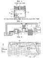
- FIG. 5 illustrates test results (a relationship between a pressure at the outlet of the filter and an elapsed time) at the 40km/h, of the conventional diesel fuel filter of FIGs. 6 and 7 and the diesel fuel filter of the present invention.
- characteristic B even after the recirculation valve 8 is closed, the recirculation valve 8 well responds to a change of the temperature of the supply-side fuel, and on and off of the recirculation valve 8 is repeated whereby the vehicle runs smoothly.
Landscapes
- Engineering & Computer Science (AREA)
- Chemical & Material Sciences (AREA)
- Combustion & Propulsion (AREA)
- Mechanical Engineering (AREA)
- General Engineering & Computer Science (AREA)
- Chemical Kinetics & Catalysis (AREA)
- Fuel-Injection Apparatus (AREA)
Abstract
A diesel fuel filter (7) has a fuel recirculation passage (5) where a recirculation valve (8) and a one-way valve (9) are provided in a disposition order of the one-way valve (9) and the recirculation valve (8) in a direction of flow of recirculation fuel in the recirculation passage (5). Due to the disposition, blockage of a fuel element (11) by a wax when the fuel temperature is low is prevented.
Description
- The present invention relates to a diesel fuel filter (a fuel filter for a diesel engine). More particularly, the present invention relates to a diesel fuel filter which can prevent blockage of a fuel filter element due to a fuel wax.
- Japanese Patent Publication No. 2002-256995 discloses a diesel fuel passage including a diesel fuel filter as illustrated in FIG. 7. The diesel fuel passage includes a
fuel supply passage 3 for use in supplying fuel from afuel tank 1 to afuel injection pump 2, afuel return passage 4 for use in returning fuel from thefuel injection pump 2 to thefuel tank 1, and afuel recirculation passage 5 for use in recirculating the fuel from thefuel return passage 4 to thefuel supply passage 3. In thefuel supply passage 3, afuel pumping pump 6 and afuel filter 7 for use in filtering foreign substances contained in fuel are provided. In thefuel recirculation passage 5, arecirculation valve 8 and a one-way valve 9 are disposed in an order of therecirculation valve 8 and the one-way valve 9 in a direction of flow of recirculation fuel. - Japanese Patent Publication No. 2003-293884 discloses a
fuel filter 7 as illustrated in FIG. 6. Thefuel filter 7 includes ahousing 10 in which afilter element 11, at least a portion of afuel recirculation passage 5, arecirculation valve 8 and a one-way valve 9 are provided in that order. A passage of flow of the fuel is the same as that of FIG 7. - In each of the fuel passage of FIG. 7 and the
fuel filter 7 of FIG 6, therecirculation valve 8 of a bimetal-type detects a fuel temperature and opens when the fuel temperature is relatively low so that a warmed fuel flowing through thefuel return passage 4 is recirculated to thefuel supply passage 3. As a result, the temperature of the fuel flowing in thefuel supply passage 3 is raised, so that a wax which has been captured by afilter element 11 is melted and blockage of thefilter element 11 due to the wax is prevented. When the fuel temperature becomes relatively high, therecirculation valve 8 is closed, so that an entire amount of the fuel flowing in thefuel return passage 4 returns to thefuel tank 1. While these are repeated, a temperature of the fuel system rises and becomes stable and therecirculation valve 8 is closed whereby warming of the supply fuel by the return fuel is off. - However, with the above-described diesel filter and the fuel passage including the diesel filter, since the
recirculation valve 8 is disposed upstream of the one-way valve 9 in the direction of flow of the recirculation fuel, a warmed fuel remains in a hatched portion of therecirculation passage 5 of FIG. 6 (between the one-way valve 9 and the recirculation valve 8) after therecirculation valve 8 is closed and when the one-way valve 9 continues to be closed. As a result, when the fuel of a low temperature and including a wax flows from thefuel tank 1 into thehousing 10, the fuel flows to thefilter element 11 without contacting therecirculation valve 8 so that therecirculation valve 8 does not open in a short time period. Further, since therecirculation valve 8 communicates with the warmed fuel in thefuel return passage 4, therecirculation valve 8 is unlikely to be open. Accordingly, opening and closing of therecirculation valve 8 cannot follow a change of the temperature of the fuel in thefuel filter 7 with a good response. As a result, after therecirculation valve 8 is closed, thefilter element 11 is blocked by a wax, and a negative pressure of the filter at an outlet of the filter is increased (causing a high negative pressure as illustrated by characteristic A in FIG. 5), so that running of the vehicle becomes unstable. - An object of the invention is to provide a diesel fuel filter which can prevent blockage of a filter element by a fuel wax when a temperature of fuel is low.
- The above object can be attained by the following diesel fuel filter according to the present invention:
- (1) The diesel fuel filter according to the present invention includes a fuel recirculation passage for use in recirculating fuel, a recirculation valve and a one-way valve provided in the fuel recirculation passage. The recirculation valve and the one-way valve are arranged in an order of the one-way valve and the recirculation valve in a direction of flow of recirculation fuel. In other words, the recirculation valve is positioned beyond the one-way valve in the direction of flow of recirculation fuel.
- (2) The diesel fuel filter of item (1) above further includes at least a portion of a fuel supply passage for use in supplying fuel from a fuel tank to a fuel injection pump. A first, downstream end of the fuel recirculation passage in a direction of flow of the recirculation fuel communicates with the at least a portion of the fuel supply passage, and a second, upstream end of the fuel recirculation passage in a direction of flow of the recirculation fuel communicates with a fuel return passage for use in returning the fuel from the fuel injection pump to the fuel tank.
- (3) The diesel fuel filter of item (1) above further includes a housing, a filter element disposed in the housing, and a space formed in the housing and below the filter element. At least a portion of the fuel recirculation passage is disposed in the space.
- (4) The diesel fuel filter of item (3) above further includes at least a portion of a fuel supply passage extending from a fuel tank to a fuel injection pump. A first, downstream end of the fuel recirculation passage in a direction of flow of the recirculation fuel communicates with the at least a portion of the fuel supply passage at the space, and a second, upstream end of the fuel recirculation passage in a direction of flow of the recirculation fuel communicates with a fuel return passage extending from the fuel injection pump to the fuel tank.
- (5) The one-way valve is a valve which allows fuel to flow only in a direction from the fuel return passage to the fuel supply passage through the fuel recirculation passage.
- (6) The recirculation valve is constructed from a bimetal valve. The bimetal valve bends in a first direction to open the fuel recirculation passage when a temperature of fuel which the bimetal valve contacts is equal to or lower than a wax melting temperature. The bimetal valve bends in a second, opposite direction to close the fuel recirculation passage when a temperature of fuel which the bimetal valve contacts is higher than the wax melting temperature.
- (7) The recirculation valve is constructed from a solenoid valve and a fuel temperature sensor which are combined such that the solenoid valve is open when the fuel temperature sensor detects that a temperature of fuel in the fuel supply passage is equal to or lower than a wax melting temperature, and the solenoid valve is closed when the fuel temperature sensor detects that the temperature of fuel in the fuel supply passage is higher than the wax melting temperature.
- With the diesel fuel filter according to any one of items (1) - (7) above, since the recirculation valve and the one-way valve are arranged in the order of the one-way valve and the recirculation valve in the direction of flow of recirculation fuel, the recirculation valve is located downstream of the one-way valve (i.e., on the side closer to the fuel supply passage), so that the recirculation valve can always contact the fuel (i.e., the supply-side fuel) in the diesel fuel filter even after the recirculation valve is closed, and the recirculation valve can follow a change of a temperature of the supply-side fuel with a good response. As a result, after the recirculation valve is closed and when the supply-side fuel is low in temperature, the recirculation valve opens in a short time period detecting the fuel temperature, thereby allowing the recirculation fuel to flow through the fuel recirculation passage and raising the temperature of the supply-side fuel to melt the wax in the fuel and to prevent blockage of the filter element by the wax.
- The above and other objects, features, and advantages of the present invention will become apparent and will be more readily appreciated from the following detailed description of the preferred embodiments of the present invention in conjunction with the accompanying drawing, in which:
- FIG. 1 is a schematic cross-sectional view of a portion of a diesel fuel filter in the vicinity of a recirculation valve according to a first embodiment of the present invention;
- FIG. 2 is a cross-sectional view of a diesel fuel filter according to the first embodiment of the present invention;
- FIG. 3 is a schematic cross-sectional view of a portion of a diesel fuel filter in the vicinity of a recirculation valve according to a second embodiment of the present invention;
- FIG. 4 is a system diagram of a fuel passage including the diesel fuel filter according to the present invention;
- FIG. 5 is a graph illustrating a test result at a low fuel temperature (a fuel pressure at an outlet of the diesel fuel filter versus a lapse of time), of the fuel passage including the diesel fuel filter according to the present invention and of a conventional fuel passage including a conventional diesel fuel filter;
- FIG. 6 is a schematic cross-sectional view of a portion of the conventional diesel fuel filter in the vicinity of a recirculation valve; and
- FIG. 7 is a system diagram of a fuel passage including the conventional diesel fuel filter.
- A diesel fuel filter according to the present invention will be explained with reference to FIGs. 1-5. FIGs. 1 and 2 illustrate a diesel fuel filter according to a first embodiment of the invention, and FIG 3 illustrates a diesel fuel filter according to a second embodiment of the invention. FIG 4 illustrates a fuel passage including the diesel fuel filter according to the present invention.
- The same elements of the fuel filter of the present invention in FIGs. 1-5 as those of the conventional fuel filter in FIGs. 6 and 7 are denoted with the same reference numerals of those of the conventional fuel filter of FIGs. 6 and 7.
- A
diesel fuel filter 7 according to the present invention is provided in afuel passage 12. As illustrated in FIG 4, thefuel passage 12 includes afuel supply passage 3 for use in supplying fuel (diesel fuel) from afuel tank 1 to afuel injection pump 2, afuel return passage 4 for use in returning the fuel from thefuel injection pump 2 to thefuel tank 1, and afuel recirculation passage 5 for use in recirculating the fuel from thefuel return passage 4 to thefuel supply passage 3. - In the
fuel supply passage 3, afuel pumping pump 6 and afilter element 11 of thefuel filter 7 for use in filtering foreign substances contained in fuel are provided. Thefuel recirculation passage 5 allows fuel to be recirculated therethrough from thefuel return passage 4 to a portion of thefuel supply passage 3 between thefuel pumping pump 6 and thefilter element 11 of the fuel filter 7 (a converging point 15). A direction of flow of the supplied fuel flowing in thefuel supply passage 3 is a direction from thefuel tank 1 to thefuel injection pump 2, and a direction of flow of the returned fuel flowing in thefuel return passage 4 is a direction from thefuel injection pump 2 to thefuel tank 1. A direction of flow of the recirculation fuel flowing in thefuel recirculation passage 5 is a direction from thefuel return passage 4 to thefuel supply passage 3. In thefuel recirculation passage 5, arecirculation valve 8 and a one-way valve 9 are disposed. - As illustrated in FIGs. 1-3, the
diesel fuel filter 7 according to the present invention includes at least a portion of thefuel recirculation passage 5. In the at least a portion of thefuel recirculation passage 5, therecirculation valve 8 and the one-way valve 9 are disposed in an order of therecirculation valve 8 and the one-way valve 9 in the direction of flow of recirculation fuel. The disposition order of therecirculation valve 8 and the one-way valve 9 in the direction of flow of recirculation fuel of the present invention is reverse to the disposition order of the one-way valve 9 and therecirculation valve 8 in the direction of flow of recirculation fuel of the conventional diesel fuel filter. - The
diesel filter 7 further includes at least a portion of thefuel supply passage 3 for use in supplying the fuel from thefuel tank 1 to thefuel injection pump 2. A downstream end of thefuel recirculation passage 5 in the direction of flow of the recirculation fuel communicates with the at least a portion of thefuel supply passage 3. An upstream end of thefuel recirculation passage 5 in the direction of flow of the recirculation fuel communicates with thefuel return passage 4 from thefuel injection pump 2 to thefuel tank 1. - The
diesel fuel filter 7 further includes ahousing 10, thefilter element 11 disposed within thehousing 10, and aspace 16 formed in thehousing 10 and below thefilter element 11. - The at least a portion of the
fuel recirculation passage 5 is disposed in thespace 16. The downstream end of thefuel recirculation passage 5 in the direction of flow of the recirculation fuel communicates with a portion between thefuel pumping pump 6 and thefilter element 11 of thefuel supply passage 3 at the convergingpoint 15 in thespace 16. In thespace 16, a passage wall of thefuel recirculation passage 5 is disposed, and in the passage wall, therecirculation valve 8 and the one-way valve 9 are disposed. - The
recirculation valve 8 is a valve which opens when a temperature of the fuel flowing in thefuel supply passage 3 is equal to or lower than a wax melting temperature, and which is closed when the temperature of the fuel flowing in thefuel supply passage 3 is higher than the wax melting temperature. When therecirculation valve 8 is open, therecirculation valve 8 allows a portion of the warmed fuel to be recirculated through thefuel recirculation passage 5 to thefuel supply passage 3 and to be mixed with the supply fuel of a low temperature thereby raising the temperature of the supply fuel at a portion of thefuel supply passage 3 upstream of thefilter element 11 to melt the wax and preventing blockage of thefilter element 11 due to the wax. When therecirculation valve 8 is closed, an entire portion of the warmed return fuel is returned to thefuel tank 1. - The one-
way valve 9 allows the fuel to flow only in a direction from thefuel return passage 4 to thefuel supply passage 3 through thefuel recirculation passage 5. The one-way valve 9 prevents the fuel from flowing in a reverse direction. - The
filter element 11 captures foreign substances and dusts contained in the fuel. When the fuel temperature is low and a wax is generated in the fuel, there is a fear that the wax is captured by thefilter element 11 to block the filter element. However, in the present invention, since therecirculation valve 8 is open, there will not happen such a blockage of thefilter element 11 due to the wax. - The
fuel pumping pump 6 is a pump to suck fuel to a position of thediesel filter 7 when the fuel system is filled with fuel. Once the fuel system has been filled with fuel, thepump 6 is not used. - The
diesel fuel filter 7 may be provided with a detector 13 (a float) for detecting water in a case where the fuel contains water and adrain portion 14 for draining the water to a drain pipe. - In a first embodiment of the present invention, as illustrated in FIGs. 1 and 2, the
recirculation valve 8 is constructed from abimetal valve 8A. Thebimetal valve 8A bends in a first direction to open thefuel recirculation passage 5 when a temperature of fuel which the bimetal valve contacts is equal to or lower than the wax melting temperature. The bimetal valve bends in a second, opposite direction to close thefuel recirculation passage 5 when the temperature of fuel which the bimetal valve contacts is higher than the wax melting temperature. However, therecirculation valve 8 should not be limited to the bimetal valve. - In a second embodiment of the present invention, the
recirculation valve 8 is constructed from asolenoid valve 8C and afuel temperature sensor 8B. Thesolenoid valve 8C and thefuel temperature sensor 8B are combined such that thesolenoid valve 8C is open when thefuel temperature sensor 8B detects that the temperature of fuel in thefuel supply passage 3 is equal to or lower than the wax melting temperature, and thesolenoid valve 8C is closed when thefuel temperature sensor 8B detects that the temperature of fuel in thefuel supply passage 3 is higher than the wax melting temperature. - Technical advantages of the present invention will now be explained.
- In the
diesel fuel filter 7 and the fuel passage including thediesel fuel filter 7, since therecirculation valve 8 and the one-way valve 9 are arranged in thefuel recirculation passage 5 in the order of the one-way valve 9 and therecirculation valve 8 in the direction of flow of recirculation fuel, therecirculation valve 8 can always contact the fuel (i.e., the supply-side fuel) in thediesel fuel filter 7 even after therecirculation valve 8 is closed, and therecirculation valve 8 can follow a change of a temperature of the supply-side fuel with a good response. Further, since the one-way valve 9 is positioned between therecirculation valve 8 and thefuel return passage 4, when therecirculation valve 8 is closed and the recirculation fuel does not flow in therecirculation passage 5, therecirculation valve 8 does not contact the warmed fuel flowing in thefuel return passage 4 and is not affected by the warmed fuel. As a result, after therecirculation valve 8 is closed and when the supply-side fuel is low in temperature, therecirculation valve 8 opens in a short time period detecting the fuel temperature, thereby allowing the recirculation fuel to flow through thefuel recirculation passage 5 and raising the temperature of the supply-side fuel to melt the wax in the fuel and to prevent blockage of thefilter element 11 by the wax. - With the conventional diesel fuel filter of FIGs. 6 and 7, since the
recirculation valve 8 and the one-way valve 9 are disposed in thefuel recirculation passage 5 in the order of therecirculation valve 8 and the one-way valve 9 in the direction of flow of the recirculation fuel, when therecirculation valve 8 is closed, warmed fuel remains between therecirculation valve 8 and the one-way valve 9. As a result, therecirculation valve 8 is unlikely to respond to the supply-side fuel of a low temperature, and a considerably long time period is required for the temperature of the fuel around therecirculation valve 8 to be low through thermal conduction through the wall of thefuel recirculation passage 5 whereby therecirculation valve 8 is open. This means that the response of the recirculation valve for opening is slow and a considerable long time period is necessary for the supply-side fuel to rise in temperature. As a result, wax is generated in the supply-side fuel which will cause blockage of thefilter element 11. Once the blockage happens, the negative pressure of thefilter element 11 becomes high accompanied by an unstable running of the vehicle. - In contrast, in the present invention, since the
recirculation valve 8 and the one-way valve 9 are disposed in thefuel recirculation passage 5 in the order of the one-way valve 9 and therecirculation valve 8 in the direction of flow of the recirculation fuel, even after therecirculation valve 8 is closed, therecirculation valve 8 can contact the supply-side fuel and can respond to a change of the temperature of the supply-side fuel. As a result, when the supply-side fuel is or becomes low in temperature, therecirculation valve 8 opens at once thereby raising the temperature of the supply-side fuel in a short time period, so that an unstable running is unlikely to happen. - FIG. 5 illustrates test results (a relationship between a pressure at the outlet of the filter and an elapsed time) at the 40km/h, of the conventional diesel fuel filter of FIGs. 6 and 7 and the diesel fuel filter of the present invention.
- In the conventional filter, as illustrated in FIG. 5 by characteristic A, after the
recirculation valve 8 is closed, thefilter element 11 is blocked by wax, and the negative pressure at the outlet of the filter becomes a high negative pressure, whereby running becomes incapable. - In contrast, in the present invention, as illustrated in FIG. 5 by characteristic B, even after the
recirculation valve 8 is closed, therecirculation valve 8 well responds to a change of the temperature of the supply-side fuel, and on and off of therecirculation valve 8 is repeated whereby the vehicle runs smoothly.
Claims (7)
- A diesel fuel filter (7) including a fuel recirculation passage (5) for use in recirculating fuel, a recirculation valve (8) and a one-way valve (9) provided in said fuel recirculation passage (5), characterized in that said recirculation valve (8) and said one-way valve (9) are arranged in an order of said one-way valve (9) and said recirculation valve (8) in a direction of flow of recirculation fuel.
- A diesel fuel filter (7) according to claim 1, further including at least a portion of a fuel supply passage (3) for use in supplying fuel from a fuel tank (1) to a fuel injection pump (2), and wherein a first, downstream end of said fuel recirculation passage (5) in a direction of flow of the recirculation fuel communicates with said at least a portion of said fuel supply passage (3), and a second, upstream end of said fuel recirculation passage (5) in a direction of flow of the recirculation fuel communicates with a fuel return passage (4) for use in returning the fuel from said fuel injection pump (2) to said fuel tank (1).
- A diesel fuel filter (7) according to claim 1, further including a housing (10), a filter element (11) disposed in said housing (10), and a space (16) formed in said housing (10) and below said filter element (11), and wherein at least a portion of said fuel recirculation passage (5) is disposed in said space (16).
- A diesel fuel filter (7) according to claim 3, further including at least a portion of a fuel supply passage (3) extending from a fuel tank (1) to a fuel injection pump (2), and wherein a first, downstream end of said fuel recirculation passage (5) in a direction of flow of the recirculation fuel communicates with said at least a portion of said fuel supply passage (3) at said space (16), and a second, upstream end of said fuel recirculation passage (5) in a direction of flow of the recirculation fuel communicates with a fuel return passage (4) extending from said fuel injection pump (2) to said fuel tank (1).
- A diesel fuel filter (7) according to any preceding claim, wherein said one-way valve (9) is a valve which allows fuel to flow only in a direction from said fuel return passage (4) to said fuel supply passage (3) through said fuel recirculation passage (5).
- A diesel fuel filter (7) according to any preceding claim, wherein said recirculation valve (8) is constructed from a bimetal valve which bends in a first direction to open said fuel recirculation passage (5) when a temperature of fuel which said bimetal valve contacts is equal to or lower than a wax melting temperature, and which bends in a second, opposite direction to close said fuel recirculation passage (5) when a temperature of fuel which said bimetal valve contacts is higher than the wax melting temperature.
- A diesel fuel filter (7) according to any one of claims 1 to 5, wherein said recirculation valve (8) is constructed from a solenoid valve (8C) and a fuel temperature sensor (8B) which are combined such that said solenoid valve (8C) is open when said fuel temperature sensor (8B) detects that a temperature of fuel in said fuel supply passage (3) is equal to or lower than a wax melting temperature, and said solenoid valve (8C) is closed when said fuel temperature sensor (8B) detects that the temperature of fuel in said fuel supply passage (3) is higher than the wax melting temperature.
Applications Claiming Priority (1)
| Application Number | Priority Date | Filing Date | Title |
|---|---|---|---|
| JP2004196395A JP2006017040A (en) | 2004-07-02 | 2004-07-02 | Diesel fuel filter and fuel path including the diesel fuel filter |
Publications (1)
| Publication Number | Publication Date |
|---|---|
| EP1612397A2 true EP1612397A2 (en) | 2006-01-04 |
Family
ID=35116086
Family Applications (1)
| Application Number | Title | Priority Date | Filing Date |
|---|---|---|---|
| EP05253656A Withdrawn EP1612397A2 (en) | 2004-07-02 | 2005-06-14 | Diesel fuel filter |
Country Status (3)
| Country | Link |
|---|---|
| EP (1) | EP1612397A2 (en) |
| JP (1) | JP2006017040A (en) |
| CN (1) | CN1715636A (en) |
Cited By (4)
| Publication number | Priority date | Publication date | Assignee | Title |
|---|---|---|---|---|
| WO2009153584A1 (en) | 2008-06-18 | 2009-12-23 | Parker Hannifin (Uk) Ltd | A liquid drain system |
| US8166943B2 (en) | 2009-07-31 | 2012-05-01 | Ford Global Technologies, Llc | Fuel system control |
| US20120204833A1 (en) * | 2011-02-10 | 2012-08-16 | Denso Corporation | Fuel injection device |
| EP3617493A1 (en) * | 2018-08-31 | 2020-03-04 | Paccar Inc | Fuel gelling prevention using engine auto start functionality |
Families Citing this family (7)
| Publication number | Priority date | Publication date | Assignee | Title |
|---|---|---|---|---|
| JP5371669B2 (en) * | 2009-09-30 | 2013-12-18 | 本田技研工業株式会社 | Scooter type vehicle |
| CN102140983B (en) * | 2011-03-21 | 2013-03-06 | 陈绍英 | Oil purifier for motor vehicle |
| JP5811888B2 (en) * | 2012-02-22 | 2015-11-11 | 株式会社デンソー | Fuel supply device |
| JP6032133B2 (en) * | 2013-06-03 | 2016-11-24 | 京三電機株式会社 | Diesel fuel supply device |
| WO2019067387A1 (en) * | 2017-09-26 | 2019-04-04 | Cummins Filtration Ip, Inc. | Return tube of a fuel filter assembly of a fuel system |
| CN111565816B (en) * | 2017-12-21 | 2022-01-21 | 康明斯滤清系统知识产权公司 | TRV stop valve |
| US12030005B2 (en) | 2018-09-20 | 2024-07-09 | Cummins Filtration Ip, Inc. | Self sufficient suction side automatic drain valve |
Citations (2)
| Publication number | Priority date | Publication date | Assignee | Title |
|---|---|---|---|---|
| JP2002256995A (en) | 2001-02-28 | 2002-09-11 | Denso Corp | Fuel supply device and fuel filtration device |
| JP2003293884A (en) | 2002-04-03 | 2003-10-15 | Kyosan Denki Co Ltd | Diesel filter |
-
2004
- 2004-07-02 JP JP2004196395A patent/JP2006017040A/en not_active Withdrawn
-
2005
- 2005-06-14 EP EP05253656A patent/EP1612397A2/en not_active Withdrawn
- 2005-06-28 CN CNA2005100797823A patent/CN1715636A/en active Pending
Patent Citations (2)
| Publication number | Priority date | Publication date | Assignee | Title |
|---|---|---|---|---|
| JP2002256995A (en) | 2001-02-28 | 2002-09-11 | Denso Corp | Fuel supply device and fuel filtration device |
| JP2003293884A (en) | 2002-04-03 | 2003-10-15 | Kyosan Denki Co Ltd | Diesel filter |
Cited By (7)
| Publication number | Priority date | Publication date | Assignee | Title |
|---|---|---|---|---|
| WO2009153584A1 (en) | 2008-06-18 | 2009-12-23 | Parker Hannifin (Uk) Ltd | A liquid drain system |
| US8733087B2 (en) | 2008-06-18 | 2014-05-27 | Parker-Hannifin (UK) Ltd. | Liquid drain system |
| US8166943B2 (en) | 2009-07-31 | 2012-05-01 | Ford Global Technologies, Llc | Fuel system control |
| US20120204833A1 (en) * | 2011-02-10 | 2012-08-16 | Denso Corporation | Fuel injection device |
| EP3617493A1 (en) * | 2018-08-31 | 2020-03-04 | Paccar Inc | Fuel gelling prevention using engine auto start functionality |
| US10934933B2 (en) | 2018-08-31 | 2021-03-02 | Paccar Inc | Fuel gelling prevention using engine auto start functionality |
| US11739686B2 (en) | 2018-08-31 | 2023-08-29 | Paccar Inc. | Fuel gelling prevention using engine auto start functionality |
Also Published As
| Publication number | Publication date |
|---|---|
| JP2006017040A (en) | 2006-01-19 |
| CN1715636A (en) | 2006-01-04 |
Similar Documents
| Publication | Publication Date | Title |
|---|---|---|
| EP1612397A2 (en) | Diesel fuel filter | |
| US6283142B1 (en) | Dual fuel delivery module system for bifurcated automotive fuel tanks | |
| US8763372B2 (en) | Method for heating a metering valve in an SCR system for the exhaust gas aftertreatment of an internal combustion engine | |
| EP0939218A2 (en) | Fuel supply apparatus | |
| US6029629A (en) | Constant fuel-pump-inlet pressure system | |
| JP4017632B2 (en) | Fuel transfer device in an engine | |
| CN221610090U (en) | Diesel filter module | |
| US20040251184A1 (en) | Fuel filter element | |
| CN115556567B (en) | A vehicle intelligent oil guiding system and its control method | |
| JP3994273B2 (en) | Fuel tank level detection valve | |
| JPS59108859A (en) | Fuel heating apparatus for diesel engine | |
| JP3810191B2 (en) | Bath equipment | |
| JPS622288Y2 (en) | ||
| JPH1181966A (en) | Engine with oil tank | |
| CN221121010U (en) | Backwater device and water heater | |
| JPH032673Y2 (en) | ||
| JPH0330622Y2 (en) | ||
| JPS59108860A (en) | Fuel heating apparatus for diesel engine | |
| JP2674337B2 (en) | Fuel supply device | |
| JPS621413Y2 (en) | ||
| JPS60257809A (en) | Fuel filter apparatus for diesel engine | |
| JPH0633825B2 (en) | Water discharge device for water separation type fuel filter | |
| JPH0221008A (en) | hydraulic circuit | |
| JPH045730Y2 (en) | ||
| JP3854202B2 (en) | Hot water supply system with hot water filling circuit |
Legal Events
| Date | Code | Title | Description |
|---|---|---|---|
| PUAI | Public reference made under article 153(3) epc to a published international application that has entered the european phase |
Free format text: ORIGINAL CODE: 0009012 |
|
| 17P | Request for examination filed |
Effective date: 20050621 |
|
| AK | Designated contracting states |
Kind code of ref document: A2 Designated state(s): AT BE BG CH CY CZ DE DK EE ES FI FR GB GR HU IE IS IT LI LT LU MC NL PL PT RO SE SI SK TR |
|
| AX | Request for extension of the european patent |
Extension state: AL BA HR LV MK YU |
|
| STAA | Information on the status of an ep patent application or granted ep patent |
Free format text: STATUS: THE APPLICATION HAS BEEN WITHDRAWN |
|
| 18W | Application withdrawn |
Effective date: 20070910 |