EP1612167A2 - Sheet material feeding apparatus - Google Patents
Sheet material feeding apparatus Download PDFInfo
- Publication number
- EP1612167A2 EP1612167A2 EP05013155A EP05013155A EP1612167A2 EP 1612167 A2 EP1612167 A2 EP 1612167A2 EP 05013155 A EP05013155 A EP 05013155A EP 05013155 A EP05013155 A EP 05013155A EP 1612167 A2 EP1612167 A2 EP 1612167A2
- Authority
- EP
- European Patent Office
- Prior art keywords
- roller
- sheet materials
- feed
- roller member
- material feeding
- Prior art date
- Legal status (The legal status is an assumption and is not a legal conclusion. Google has not performed a legal analysis and makes no representation as to the accuracy of the status listed.)
- Withdrawn
Links
Images


Classifications
-
- B—PERFORMING OPERATIONS; TRANSPORTING
- B65—CONVEYING; PACKING; STORING; HANDLING THIN OR FILAMENTARY MATERIAL
- B65H—HANDLING THIN OR FILAMENTARY MATERIAL, e.g. SHEETS, WEBS, CABLES
- B65H1/00—Supports or magazines for piles from which articles are to be separated
- B65H1/02—Supports or magazines for piles from which articles are to be separated adapted to support articles on edge
- B65H1/025—Supports or magazines for piles from which articles are to be separated adapted to support articles on edge with controlled positively-acting mechanical devices for advancing the pile to present the articles to the separating device
-
- B—PERFORMING OPERATIONS; TRANSPORTING
- B65—CONVEYING; PACKING; STORING; HANDLING THIN OR FILAMENTARY MATERIAL
- B65H—HANDLING THIN OR FILAMENTARY MATERIAL, e.g. SHEETS, WEBS, CABLES
- B65H1/00—Supports or magazines for piles from which articles are to be separated
- B65H1/08—Supports or magazines for piles from which articles are to be separated with means for advancing the articles to present the articles to the separating device
-
- B—PERFORMING OPERATIONS; TRANSPORTING
- B65—CONVEYING; PACKING; STORING; HANDLING THIN OR FILAMENTARY MATERIAL
- B65H—HANDLING THIN OR FILAMENTARY MATERIAL, e.g. SHEETS, WEBS, CABLES
- B65H3/00—Separating articles from piles
- B65H3/02—Separating articles from piles using friction forces between articles and separator
- B65H3/06—Rollers or like rotary separators
- B65H3/0653—Rollers or like rotary separators for separating substantially vertically stacked articles
-
- B—PERFORMING OPERATIONS; TRANSPORTING
- B65—CONVEYING; PACKING; STORING; HANDLING THIN OR FILAMENTARY MATERIAL
- B65H—HANDLING THIN OR FILAMENTARY MATERIAL, e.g. SHEETS, WEBS, CABLES
- B65H9/00—Registering, e.g. orientating, articles; Devices therefor
-
- B—PERFORMING OPERATIONS; TRANSPORTING
- B65—CONVEYING; PACKING; STORING; HANDLING THIN OR FILAMENTARY MATERIAL
- B65H—HANDLING THIN OR FILAMENTARY MATERIAL, e.g. SHEETS, WEBS, CABLES
- B65H2511/00—Dimensions; Position; Numbers; Identification; Occurrences
- B65H2511/20—Location in space
- B65H2511/21—Angle
- B65H2511/214—Inclination
-
- B—PERFORMING OPERATIONS; TRANSPORTING
- B65—CONVEYING; PACKING; STORING; HANDLING THIN OR FILAMENTARY MATERIAL
- B65H—HANDLING THIN OR FILAMENTARY MATERIAL, e.g. SHEETS, WEBS, CABLES
- B65H2701/00—Handled material; Storage means
- B65H2701/10—Handled articles or webs
- B65H2701/19—Specific article or web
- B65H2701/1916—Envelopes and articles of mail
Definitions
- the present invention relates to a sheet material feeding apparatus that feeds a sheet material such as a postal matter.
- sheet material feeding apparatus As a sheet material feeding apparatus of this kind, there is known a type in which sheet materials are placed in a standing position on a floor belt and they are conveyed to a feed-out unit as the floor belt runs. At the feed-out unit, sheet materials are fed out one by one as feed-out roller or feed-out belt rotates.
- stacked sheet materials are conveyed in an inclined state as relative to the feed-out unit as being affected so for one reason or another or the stacked sheet materials are already set in an inclined state on the floor belt before they are conveyed.
- the sheet materials are not evenly brought into contact with the feed-out roller or feed-out belt, and thus an uneven contacting state is created.
- the sheet materials are fed out in this state, such problems occur that sheets are skewed and continuous feeding out of sheets is interrupted.
- the present invention has been proposed in consideration of the above-described circumstances of the conventional technique and its object is to provide a sheet material feeding apparatus with a simple structure, which can correct the inclination of stacked sheet materials without the possibility of damaging any of the materials.
- a sheet material feeding apparatus comprising: a conveying device that conveys stacked sheet materials in a stacking direction in a standing state; a feed-out device that brings the stacked sheet materials conveyed by the conveying device into contact with a feed-out roller and feeds the sheet materials out in a direction crossing the conveying direction of the stacked sheet materials by rotation of the feed-out roller; a guide unit that guides the sheet materials fed out by the feed-out device along a guide surface such as to project a part of the feed-out roller from the guide surface; and an inclination correcting device provided in an upstream of the feed-out device in its sheet material feeding direction and including a roller member located at a position higher than that of the feed-out roller, that brings an upper side of the stacked sheet materials conveyed towards the feed-out device into contact with the roller member to correct the inclination of the stacked sheet materials.
- the inclination of stacked sheet materials can be corrected merely by bringing the sheet materials into contact with the roller member of the inclination correcting device.
- the invention has a simple structure and does not damage sheet materials. Further, the sheet materials are handled to displaced from each other to be fed out, and thus they can be separated surely one by one.
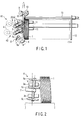
- FIG. 1 is a plan view schematically showing the structure of a sheet material feeding apparatus according to the first embodiment of the present invention.
- This sheet material feeding apparatus includes a floor belt 11 serving as a conveying device that conveys stacked sheet materials 1 placed thereon in a standing position. A rear end side of the stacked sheet materials 1 with respect to the direction of the materials being conveyed by the floor belt 11 is held with a pressure by a backup plate 12. The backup plate 12 is moved along a backup plate shaft 13.
- the first and second feeding mechanisms K1 and K2 are provided as a feed-out device. Sheet materials are fed by the first and second feeding mechanisms K1 and K2 in a direction that crosses the direction of conveying the stack sheet materials 1. Further, a guide plate 15 serving as a guide member is provided along the direction of feeding sheet materials, and while conveying the sheet materials, they are guided along a guide surface 15a of the guide plate 15.
- the first feeding mechanism K1 includes upper and lower pick-up rollers 2a and 2b and these pick-up rollers 2a and 2b are each supported by a pick-up arm 3.
- a drive motor 4 is connected to the pick-up roller 2 via a timing belt 2.
- the second feeding mechanism K2 has a similar structure to that of the first feeding mechanism 1, and therefore similar parts are designated by the same reference symbols and the explanations therefor will be omitted.
- an inclination correcting mechanism 6 is provided as an inclination correcting device to correct the inclination of the stacked sheet materials 1, which will be described in detail later.
- the inclination correcting mechanism 6 is rotatably supported by one end of a support arm 7 serving as a support device.
- the support arm 7 is pivotably supported on a pivot 7a by its middle portion and the other end thereof is urged by a spring member 8. With the urging force of the spring member 8, the inclination correcting mechanism 6 is brought into contact with a pressure on the upper side of the rear end side of the stacked sheet materials in the feeding direction.
- a feed roller 9 is provided to feed sheet materials to the downstream, and a reverse roller 10 is provided for the feed roller 9 in order to separate materials from the next sheet on by applying a counter-rotating torque thereto.
- FIG. 2 is a front view showing the inclination correcting mechanism 6 described above.
- the inclination correcting mechanism 6 includes a support shaft 14.
- An upper roller 6a serving as an upper end roller member is provided on an upper end portion of the support shaft 14, a middle roller 6b is mounted in a middle portion thereof, and a lower roller 6c is mounted in a lower portion thereof.
- the support shaft 14 is inclined to make a predetermined angle with respect to the normal line. In other words, the support shaft 14 is inclined such that the upper end side thereof is set close to the stacked sheet materials 1, whereas the lower end side is distant from the stacked sheet materials 1.
- the rollers 6a to 6c are arranged to be in parallel with each other, and they all have the same diameter.
- the inclining angle of the support shaft 14 is set to 4° , and the heights of the rollers 6a to 6c, that is, the height to a corner portion that is brought into contact with sheet materials in each, are 140 mm for the upper roller 9a, 90 mm for the middle roller 6b and 20 mm for the lower roller 6c.
- the amount of projection of the upper roller 6a and middle roller 6b from the guide plate 15 is set a predetermined amount larger than the projecting amount of the pickup roller 2 from the guide plate 15.
- the projecting amount of the lower roller 6c is set smaller than the projecting amount of the lower pickup roller 2b.
- the stacked sheet materials 1 are set in a standing position on the floor belt 11, and then the floor belt 11 and backup plate 12 are moved in the direction indicated in FIG. 1 to convey the stacked sheet materials 1. While this operation, if the stacked sheet materials 1 are conveyed in an inclined state, for example, while being inclined such that the upper side of the stack is close to the pickup roller 2b, whereas the lower side thereof is distant from the pickup roller 2b, as shown in FIG. 2, the upper side of the stack of the sheet materials 1 is brought into contact with a pressure with the upper roller 6a so that the upper side is pushed back. In this manner, the inclination of the stacked sheet materials 1 is corrected so that they stand straight up.
- an inclined state for example, while being inclined such that the upper side of the stack is close to the pickup roller 2b, whereas the lower side thereof is distant from the pickup roller 2b, as shown in FIG. 2
- the upper side of the stack of the sheet materials 1 is brought into contact with a pressure with the upper roller 6a so that the upper side is pushed
- the stacked sheet materials 1 are set to abut against the pickup rollers 2a and 2b.
- Sheet materials abutting against the pickup rollers 2a and 2b are fed to the feed roller 9 as the pickup rollers 2a and 2b rotate. While this operation, the rollers 6a and 6b are rotated to follow the rotation of the pickup rollers 2a and 2b via a respective sheet material, thereby making it possible to reduce the load during the feeding.
- the fed sheet materials are separated one by one from each other by the rotations of the feed roller 9 and reverse roller 10, and they are conveyed to the downstream as indicated by a white arrow in FIG. 1.
- FIG. 3 illustrates the details of the operation of the upper roller 6a of the inclination correcting mechanism 6.
- the component of the force that acts in the planer direction of the sheet materials is larger than the component of the force that acts in the stacking direction of the sheet materials.
- the component of the force that acts in the stacking direction of the sheet materials serves as a force to support the sheet materials being conveyed in the inclined state
- the component of the force that acts in the planer direction of the sheet materials serves as a force to feed the sheet materials.
- the stacked sheet materials 1 are shifted from the beginning state where they are pushed in the direction of correcting its inclination to the state where they are fed in the feeding direction. This transition of the state is very convenient to maintain the continuous sheet material feeding operation.
- the outer diameter of the upper roller 6a is set to ⁇ 40 mm
- the radius of pivoting is set to 40 mm
- the projecting amount from the guiding plate 15 is set to 20 mm ⁇ 2 mm.
- the pivotable range ⁇ of the upper roller 6a is set to 35° to 65°
- the value of F is set to 7.2N (0.8 kgf) to 14.7N (1.5 kgf), which is set by arranging the spring member 8 appropriately and selecting an appropriate spring constant.
- sample envelopes were prepared and a continuous feeding test was carried out.
- sample envelopes were those of a size C5 (229 mm ⁇ 162 mm), and different contents were enclosed in the envelopes, with such an adjustment of the ratio in the number of envelopes so that the weights of the envelope vary from 10g to 50g, at an average of 25g.
- the length of the sheet materials was varied from 220 mm to 250 mm and the test was carried out. In each case, it was possible to stably and continuously carry out the feeding out operations at an average gap of 108 to 112 mm and an accuracy of a standard deviation of 6 to 10 mm.
- This embodiment is appropriate for such usage that sheet materials of a length from 220 mm to 250 mm are handled, and it is a feeding out apparatus with an excellent performance in handling, mainly, envelops of the size C5.
- the upper, middle and lower rollers 6a to 6c are fixed onto the common arm 7 by the shaft 14, but it is alternatively and perfectly possible to prepare separate arms for the respective rollers in an independent suspension structure.
- FIG. 4 is a front view showing an inclination correcting mechanism 21 according to the second embodiment of the present invention.
- the inclination correcting mechanism 21 is provided vertically without being inclined. That is, the support shaft 14 is provided vertically, and an upper roller having a large diameter, a middle roller 17 having a middle diameter and a lower roller 18 having a small diameter are mounted on the support shaft 14 horizontally at predetermined intervals.
- the effect of the present invention can be best obtained by arranging the inclination correcting mechanisms 6 and 21 to match the length of sheet materials that are handled mostly.
- the length of sheet materials to be handled varies, it is natural to change the arrangement to obtain a similar effect to that.
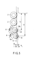
- FIG. 5 is a plan view showing first and second inclination correcting mechanisms 19 and 20 according to the third embodiment of the present invention.
- the first and second inclination correcting mechanisms 19 and 20 are provided in a multiple arrangement along the feeing out direction of sheet materials. With this arrangement, the apparatus becomes able to deal with such a situation that sheet materials with different lengths are handled at the same time.
- first and second inclination correcting mechanisms 19 and 20 are arranged in a multiple manner, it is necessary to clear the condition that the first inclination correcting mechanisms 19, which is located on the upstream side in the sheet material feeding direction, must be placed such that the projecting amount of the first inclination correcting mechanisms 19 from the guide plate 15 is larger than that of the second inclination correcting mechanism 20, which is located on the downstream side.
- the first inclination correcting mechanisms 19 is designed to support sheet materials with relatively large sizes, whereas the second inclination correcting mechanism 20 is designed to support sheet materials with relatively small sizes.
- Each of the first and second inclination correcting mechanisms 19 and 20 is set at an inclining angle of 4° as in the case of the first embodiment.
- first inclination correcting mechanisms 19 there are three rollers, that is, the upper, middle and lower ones are provided, whereas for the second inclination correcting mechanisms 20, there are two rollers, that is, the middle and lower ones, without the upper one, are provided.
- the projecting amount of the first inclination correcting mechanism 19 from the guiding plate 15 is set larger by d1 (10 mm) as compared to the projecting amount of the pickup roller 2 from the guiding plate 15, and a distance L1 from a central portion of the upper roller 19a to the leading end surface of the sheet materials is 238 mm.
- the projecting amount of the second inclination correcting mechanism 20 from the guiding plate 15 is set larger by d2 (4 mm) as compared to the projecting amount of the pickup roller 2 from the guiding plate 15, and a distance L2 from a central portion of the middle roller 20a to the leading end surface of the sheet materials is 218 mm.
- the arrangement of the first inclination correcting mechanism 19 is based on a case were large-sized post cards having a length of about 210 mm (widely popular in, for example, Europe) are handled.
- the reason why the projecting amount of the first inclination correcting mechanism 19 is set larger that of the second inclination correcting mechanism 20 is to prevent the second inclination correcting mechanism 20 from being brought into contact with a middle portion of a sheet material, especially, when the sheet material is of a larger size, which creates a loading resistance when feeding out sheet materials.
- the second inclination correcting mechanism 20 is designed for sheet materials having relatively short lengths. In many cases, sheet materials of short lengths do not have such heights for their lengths, and therefore the inclination correcting amount for a stack of such sheet materials may be less to be sufficient. Therefore, it is not necessary to set a large projecting amount for this mechanism.
- the length of the sheet materials was varied from 160 mm to 250 mm and the test was carried out. In each case, it was possible to stably and continuously carry out the feeding out operations at an average gap of 110 to 120 mm and an accuracy of a standard deviation of 8 to 13 in each case.
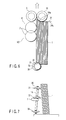
- FIG. 6 is a plan view showing an inclination correcting mechanism 30 according to the fourth embodiment of the present invention, and FIG. 7 shows its front view.
- the inclination correcting mechanisms 30 of this embodiment includes a support shaft 14, to which an upper roller 31 serving as the first roller, a middle roller 32 and a lower roller 33 serving as the second roller are mounted at an upper end portion, middle portion and lower portion thereof.
- the upper, middle and lower rollers 31 to 33 are arranged to be in parallel with each other, and the sizes of their diameters have the relationship of the upper roller 31 ⁇ the middle roller 32 ⁇ the lower roller 33.
- the outer diameter of the upper roller 31 is ⁇ 34 mm
- the outer diameter of the middle roller 32 is ⁇ 37 mm
- the outer diameter of the lower roller 33 is ⁇ 43 mm.
- the heights of the upper, middle and lower rollers 31 to 33 that is, the heights taken at corner portions that are brought into contact with the sheet materials, are set to 140 mm, 90 mm and 20 mm, respectively.
- the radius of pivoting of the support arm 7 is set to 40 mm, and the projecting amount d of each of the upper, middle and lower rollers 31 to 33 from the guide plate 15 is set to 20 mm ⁇ 2 mm.
- the distance L from an evening surface 34 of the guide plate 34, which evens the edges of the sheet materials, to the center of the support shaft 14 is set to 241 mm ⁇ 2 mm.
- the radius of an R section 34b of the guide member 34 serving to guide the leading edges of the stacked sheet materials 1 between a feed roller 9 and a reverse roller 10 is set to 22 mm.
- the radius of the lower roller 33 is set substantially equal to the radium of the R section 34b of the guide plate 34.
- the inclination correcting mechanism 30 having the above-described structure was subjected to feeding tests, in which sheet materials of sample envelopes of a size C5 (229 mm ⁇ 162 mm), which is most popularly used outside Japan for the usage of direct mails in particular, are continuously fed.
- the stacked sheet materials 1 are conveyed in an inclined state as shown in FIG. 7, the upper side of the stack of the sheet materials 1 is brought into contact with a pressure with the upper roller 31 and middle roller 32 so that the upper side is pushed back. In this manner, the inclination of the stacked sheet materials 1 is corrected so that they stand straight up.
- a component of the force that acts in the stacking direction of the sheet materials and a component of the force that acts in the planer direction of the sheet materials are created.
- the component that acts in the stacking direction of the sheet materials serves as a force to support the sheet materials being conveyed in the inclined state, whereas the component that acts in the planer direction serves as a force to feed the sheet materials.
- the outer diameter of the lower roller 33 is set larger than that of the upper roller 31, and substantially equal to the radius of the R section of the guide plate 34.
- the outer diameter of the upper roller 31 is made larger to be equal to that of the lower roller 33, the phase between the outer diameter of the upper roller 31 and the R section 34b of the guide plate 34 is shifted. More specifically, the distance between the upper roller 31 and the guide plate 34 becomes smaller than 229 mm, which is a length of a C5 size.
- the rear end of a sheet material in its feeding-out direction may be caught in the upper roller 31, thereby failing to set displacement between the sheet materials by the upper roller 31.
- the sheet materials enters the pressure contact portion between the feed roller 9 and reverse roller 10 without having a displacement of edges between sheet materials, and therefore the frequency of feeding two or more sheet materials in stack erroneously without being separated from each other is increased.
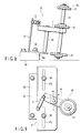
- FIG. 8 is a front view showing a support mechanism 35 of the inclination correcting mechanism described above, and FIG. 9 is a plan view of the support mechanism.
- the figure shows a substrate 36, a mount surface 36a is formed on its upper surface portion to be inclined.
- a support bracket 37 having a cross section of an L shape is mounted with a bolt 38 on the mount surface 36a of the substrate 36.
- elongated holes 37a are made in a bottom surface portion of the support bracket 37 along the direction of feeding the sheet materials.
- the support bracket 37 is fixed with bolts 38 inserted to the elongated holes 37a and 37b. As the bolts 38 are loosened, the support bracket 37 is slid to move in the longitudinal direction of the elongated holes 37a.
- a shaft 40 is provided to stand at a central portion of a bottom surface of the support bracket 37, and a middle portion of the pivot arm 7 is pivotably mounted to the upper end portion of the shaft 40.
- the support shaft 14 is mounted to one end of the pivot arm 7, and upper, middle and lower rollers 31 to 33 are mounted to the support shaft 14.
- the other end of the pivot arm 7 is connected to the support bracket 37 via a spring member 8.
- the inclination correcting mechanism 30 supported as above is moved to change its position in accordance with the size of sheet materials to be fed.
- the bolts 38 are loosened and the support bracket 37 is slid to move as indicated by an arrow of a solid line to increase the distance between the rollers 31 to 33 and the guide plate 34. Then, the bolts 38 are tightened to fix the support bracket 37.
- the support bracket 37 is slid to move as indicated by an arrow of a broken line to decrease the distance between the rollers 31 to 33 and the guide plate 34.
- FIG. 10 is a plan view showing an inclination correcting mechanism 51 according to the fifth embodiment of the present invention
- FIG. 11 is a front view thereof.
- the inclination correcting mechanism 51 includes an inclined support shaft 14 as in the case of the inclination correcting mechanism 30 described above, and a cylindrical roller member 53 is rotatably mounted to the support shaft 14.
- the roller member 53 is formed such that the diameter thereof gradually decreases from its lower end portion to the upper end portion.
- the upper and lower portions of the support shaft 14 are supported by pivot arms 56.
- An upper side 53a of the roller member 53 is located at a level higher than that of a pickup roller 2a, and the radium of a lower side 53b is set substantially equal to the radius of an R section 34b of a guide plate 34.
- the inclination correcting mechanism 51 having the above-described structure, if the stacked sheet materials 1 are conveyed in an inclined state as shown in FIG. 11, and the upper side of the stack of the sheet materials 1 is brought into contact with a pressure with the upper side of the roller member 53, the upper side is pushed back. In this manner, the inclination of the stacked sheet materials 1 is corrected so that they stand straight up.
- the stacked sheet materials can be handled to displace from each other as in the case of the inclination correcting mechanism 30.
- the sheet materials can be allowed to enter between the feed roller 9 and reverse roller 10 while being displaced from each other, thereby making it possible to surely separate the sheet materials from each other.
Landscapes
- Engineering & Computer Science (AREA)
- Mechanical Engineering (AREA)
- Sheets, Magazines, And Separation Thereof (AREA)
- Registering Or Overturning Sheets (AREA)
Abstract
Description
- The present invention relates to a sheet material feeding apparatus that feeds a sheet material such as a postal matter.
- As a sheet material feeding apparatus of this kind, there is known a type in which sheet materials are placed in a standing position on a floor belt and they are conveyed to a feed-out unit as the floor belt runs. At the feed-out unit, sheet materials are fed out one by one as feed-out roller or feed-out belt rotates.
- However, in some cases, stacked sheet materials are conveyed in an inclined state as relative to the feed-out unit as being affected so for one reason or another or the stacked sheet materials are already set in an inclined state on the floor belt before they are conveyed. In such cases, the sheet materials are not evenly brought into contact with the feed-out roller or feed-out belt, and thus an uneven contacting state is created. When the sheet materials are fed out in this state, such problems occur that sheets are skewed and continuous feeding out of sheets is interrupted.
- As a solution to this, such a conventional technique was developed as disclosed in, for example, Jpn. Pat. Appln. KOKAI Publication No. 2002-68490, in which the floor belt is divided and a lever is provided to convey sheet materials while detecting the clearance between sheet materials (, which is roughly equivalent to the inclining state), to realize stable feeding out of the materials.
- However, with the above-described method, a mechanism for operating the lever is necessary, which makes the structure of the device complicated, and there is such a drawback that sheet material may be damaged when the lever fails to function properly.
- The present invention has been proposed in consideration of the above-described circumstances of the conventional technique and its object is to provide a sheet material feeding apparatus with a simple structure, which can correct the inclination of stacked sheet materials without the possibility of damaging any of the materials.
- According to an aspect of the present invention, there is provided a sheet material feeding apparatus comprising: a conveying device that conveys stacked sheet materials in a stacking direction in a standing state; a feed-out device that brings the stacked sheet materials conveyed by the conveying device into contact with a feed-out roller and feeds the sheet materials out in a direction crossing the conveying direction of the stacked sheet materials by rotation of the feed-out roller; a guide unit that guides the sheet materials fed out by the feed-out device along a guide surface such as to project a part of the feed-out roller from the guide surface; and an inclination correcting device provided in an upstream of the feed-out device in its sheet material feeding direction and including a roller member located at a position higher than that of the feed-out roller, that brings an upper side of the stacked sheet materials conveyed towards the feed-out device into contact with the roller member to correct the inclination of the stacked sheet materials.
- According to the above-described embodiment of the present invention, the inclination of stacked sheet materials can be corrected merely by bringing the sheet materials into contact with the roller member of the inclination correcting device. Thus, the invention has a simple structure and does not damage sheet materials. Further, the sheet materials are handled to displaced from each other to be fed out, and thus they can be separated surely one by one.
- This summary of the invention does not necessarily describe all necessary features so that the invention may also be a sub-combination of these described features.
- The invention can be more fully understood from the following detailed description when taken in conjunction with the accompanying drawings, in which:
- FIG. 1 is a plan view showing a sheet material feeding apparatus according to the first embodiment of the present invention;
- FIG. 2 is a front view showing a mechanism of correcting inclination of stacked sheet materials in the sheet material feeding apparatus;
- FIG. 3 is a diagram showing a force applied to stacked sheet materials by the inclination correcting mechanism;
- FIG. 4 is a front view showing an inclination correcting mechanism according to the second embodiment of the present invention;
- FIG. 5 is a plan view showing a set of inclination correcting mechanisms according to the third embodiment of the present invention;
- FIG. 6 is a plan view showing an inclination correcting mechanism according to the fourth embodiment of the present invention;
- FIG. 7 is a front view of the inclination correcting mechanism shown in FIG. 6;
- FIG. 8 is a front view showing a moving mechanism of the inclination correcting mechanism shown in FIG. 6;
- FIG. 9 is a plan view of moving mechanism shown in FIG. 8;
- FIG. 10 is a plan view showing an inclination correcting mechanism according to the fifth embodiment of the present invention; and
- FIG. 11 is a front view of the inclination correcting mechanism shown in FIG. 10.
- Embodiments of the present invention will now be described in detail with reference to accompanying drawings.
- FIG. 1 is a plan view schematically showing the structure of a sheet material feeding apparatus according to the first embodiment of the present invention.
- This sheet material feeding apparatus includes a
floor belt 11 serving as a conveying device that conveys stackedsheet materials 1 placed thereon in a standing position. A rear end side of the stackedsheet materials 1 with respect to the direction of the materials being conveyed by thefloor belt 11 is held with a pressure by abackup plate 12. Thebackup plate 12 is moved along abackup plate shaft 13. - In the downstream of the conveying direction of the stacked
sheet materials 1, the first and second feeding mechanisms K1 and K2 are provided as a feed-out device. Sheet materials are fed by the first and second feeding mechanisms K1 and K2 in a direction that crosses the direction of conveying thestack sheet materials 1. Further, aguide plate 15 serving as a guide member is provided along the direction of feeding sheet materials, and while conveying the sheet materials, they are guided along a guide surface 15a of theguide plate 15. - The first feeding mechanism K1 includes upper and lower pick-
up rollers up rollers up arm 3. Adrive motor 4 is connected to the pick-up roller 2 via atiming belt 2. The second feeding mechanism K2 has a similar structure to that of thefirst feeding mechanism 1, and therefore similar parts are designated by the same reference symbols and the explanations therefor will be omitted. - In the upstream of the sheet material feeding direction of the second feeding mechanism K2, an
inclination correcting mechanism 6 is provided as an inclination correcting device to correct the inclination of the stackedsheet materials 1, which will be described in detail later. - The
inclination correcting mechanism 6 is rotatably supported by one end of asupport arm 7 serving as a support device. Thesupport arm 7 is pivotably supported on apivot 7a by its middle portion and the other end thereof is urged by aspring member 8. With the urging force of thespring member 8, theinclination correcting mechanism 6 is brought into contact with a pressure on the upper side of the rear end side of the stacked sheet materials in the feeding direction. - In the feeding direction of sheet materials, a
feed roller 9 is provided to feed sheet materials to the downstream, and areverse roller 10 is provided for thefeed roller 9 in order to separate materials from the next sheet on by applying a counter-rotating torque thereto. - FIG. 2 is a front view showing the
inclination correcting mechanism 6 described above. - The
inclination correcting mechanism 6 includes asupport shaft 14. Anupper roller 6a serving as an upper end roller member is provided on an upper end portion of thesupport shaft 14, amiddle roller 6b is mounted in a middle portion thereof, and alower roller 6c is mounted in a lower portion thereof. Thesupport shaft 14 is inclined to make a predetermined angle with respect to the normal line. In other words, thesupport shaft 14 is inclined such that the upper end side thereof is set close to the stackedsheet materials 1, whereas the lower end side is distant from the stackedsheet materials 1. Therollers 6a to 6c are arranged to be in parallel with each other, and they all have the same diameter. - The inclining angle of the
support shaft 14 is set to 4° , and the heights of therollers 6a to 6c, that is, the height to a corner portion that is brought into contact with sheet materials in each, are 140 mm for the upper roller 9a, 90 mm for themiddle roller lower roller 6c. - The amount of projection of the
upper roller 6a andmiddle roller 6b from theguide plate 15 is set a predetermined amount larger than the projecting amount of thepickup roller 2 from theguide plate 15. With this arrangement, as stacked sheet materials becomes higher and more easily inclined, the inclination of the stack is more corrected as the stack abuts against the rollers of the upper side. - It should be noted here that if the
lower roller 6c is set to project in a similar manner to those of therollers lower pickup roller 2b. In order to avoid this, the projecting amount of thelower roller 6c is set smaller than the projecting amount of thelower pickup roller 2b. - Next, the feeding operation of the sheet material feeding apparatus will now be described.
- First, the stacked
sheet materials 1 are set in a standing position on thefloor belt 11, and then thefloor belt 11 andbackup plate 12 are moved in the direction indicated in FIG. 1 to convey the stackedsheet materials 1. While this operation, if the stackedsheet materials 1 are conveyed in an inclined state, for example, while being inclined such that the upper side of the stack is close to thepickup roller 2b, whereas the lower side thereof is distant from thepickup roller 2b, as shown in FIG. 2, the upper side of the stack of thesheet materials 1 is brought into contact with a pressure with theupper roller 6a so that the upper side is pushed back. In this manner, the inclination of the stackedsheet materials 1 is corrected so that they stand straight up. After the inclination is corrected as described, the stackedsheet materials 1 are set to abut against thepickup rollers pickup rollers feed roller 9 as thepickup rollers rollers pickup rollers feed roller 9 andreverse roller 10, and they are conveyed to the downstream as indicated by a white arrow in FIG. 1. - FIG. 3 illustrates the details of the operation of the
upper roller 6a of theinclination correcting mechanism 6. - Due to the urging force of the
spring member 8, there is created a force applied to theupper roller 6a to move in the directed indicated by arrow F. The upper side of the rear end of thestacked sheet materials 1 is pushed against theupper roller 6a. Here, the direction of the force propagated to thestacked sheet materials 1 changes depending upon with which part of theupper roller 6a thestacked sheet materials 1 are brought into contact. More specifically, at a position fa which corresponds to a relatively beginning stage where the stack ofsheet materials 1 are brought into contact with theupper roller 6a, the component of the force that acts in the stacking direction of the sheet materials is larger than the component of the force that acts in the planer direction of the sheet materials. On the other hand, at a position fb which corresponds to a relatively ending stage of the contact between the stack ofsheet materials 1 and theupper roller 6a, the component of the force that acts in the planer direction of the sheet materials is larger than the component of the force that acts in the stacking direction of the sheet materials. - It should be noted here that the component of the force that acts in the stacking direction of the sheet materials serves as a force to support the sheet materials being conveyed in the inclined state, whereas the component of the force that acts in the planer direction of the sheet materials serves as a force to feed the sheet materials.
- Therefore, the
stacked sheet materials 1 are shifted from the beginning state where they are pushed in the direction of correcting its inclination to the state where they are fed in the feeding direction. This transition of the state is very convenient to maintain the continuous sheet material feeding operation. - Further, as the component of the force applied on the
stacked sheet materials 1 shifts its direction, such an effect of separating the stacked sheet materials from each other, which is so called "handling effect", is obtained. Thus, the load resistance due to the tightly stacking of the sheet materials, can be reduced. - As described, due to the effect obtained by the arrangement of the
inclination correcting mechanism 6, a stable feeding out operation can be carried out even if stacked sheet materials, for example, fall. - In this embodiment, the outer diameter of the
upper roller 6a is set to φ 40 mm, the radius of pivoting is set to 40 mm, and the projecting amount from the guidingplate 15 is set to 20 mm ± 2 mm. - Further, the pivotable range θ of the
upper roller 6a is set to 35° to 65° , and the value of F is set to 7.2N (0.8 kgf) to 14.7N (1.5 kgf), which is set by arranging thespring member 8 appropriately and selecting an appropriate spring constant. - Under the above-described conditions, sample envelopes were prepared and a continuous feeding test was carried out.
- The sample envelopes were those of a size C5 (229 mm × 162 mm), and different contents were enclosed in the envelopes, with such an adjustment of the ratio in the number of envelopes so that the weights of the envelope vary from 10g to 50g, at an average of 25g.
- When the apparatus was operated with a control order of feeding the sheet materials at a conveying speed of 3.6 m/s and a constant gap of 100 mm (, which is equivalent to 38.2k envelopes/h), it was possible to stably and continuously carry out the feeding out operation at an average gap of 109.4 mm and an accuracy of a standard deviation of 10 mm.
- Further, since the
upper roller 6a was set swingable, and therefore a similar effect to the above can be obtained regardless of the length of the sheet materials as long as it is within the swinging range. - Actually, the length of the sheet materials was varied from 220 mm to 250 mm and the test was carried out. In each case, it was possible to stably and continuously carry out the feeding out operations at an average gap of 108 to 112 mm and an accuracy of a standard deviation of 6 to 10 mm.
- This embodiment is appropriate for such usage that sheet materials of a length from 220 mm to 250 mm are handled, and it is a feeding out apparatus with an excellent performance in handling, mainly, envelops of the size C5.
- Here, for sheet materials of a length of less than 220 mm, it is possible to feed out them stably by means of the feeding out force of the
pickup roller 2 itself even without theupper roller 6a. Therefore, it is sufficiently possible to handle sheet materials of shorter lengths. - Further, in this embodiment, the upper, middle and
lower rollers 6a to 6c are fixed onto thecommon arm 7 by theshaft 14, but it is alternatively and perfectly possible to prepare separate arms for the respective rollers in an independent suspension structure. - FIG. 4 is a front view showing an
inclination correcting mechanism 21 according to the second embodiment of the present invention. - In the second embodiment, the
inclination correcting mechanism 21 is provided vertically without being inclined. That is, thesupport shaft 14 is provided vertically, and an upper roller having a large diameter, amiddle roller 17 having a middle diameter and alower roller 18 having a small diameter are mounted on thesupport shaft 14 horizontally at predetermined intervals. - With this structure, as the stacked sheet materials become higher and more easily inclined, they abut more against the upper roller for a better support.
- Similar tests to those of the first embodiment were conducted under such conditions that the diameters of the
upper roller 16,middle roller 17 andlower roller 18 were set to φ56 mm, φ50 mm, and φ40 mm, it was possible to stably and continuously carry out the feeding out operations on sheet materials of a length of 220 mm to 250 mm at an average gap of 109 mm to 112 mm and an accuracy of a standard deviation of 7 to 11. - As described above, it is not necessary to incline the whole inclination correcting mechanism, but a similar effect to that of the first embodiment can be obtained by setting the different diameters for the
rollers 16 to 18. - It should be pointed out that as described in connection with the first and second embodiments, the effect of the present invention can be best obtained by arranging the
inclination correcting mechanisms - FIG. 5 is a plan view showing first and second
inclination correcting mechanisms - In this embodiment, the first and second
inclination correcting mechanisms - In the case where the first and second
inclination correcting mechanisms inclination correcting mechanisms 19, which is located on the upstream side in the sheet material feeding direction, must be placed such that the projecting amount of the firstinclination correcting mechanisms 19 from theguide plate 15 is larger than that of the secondinclination correcting mechanism 20, which is located on the downstream side. - The first
inclination correcting mechanisms 19 is designed to support sheet materials with relatively large sizes, whereas the secondinclination correcting mechanism 20 is designed to support sheet materials with relatively small sizes. - Each of the first and second
inclination correcting mechanisms inclination correcting mechanisms 19, there are three rollers, that is, the upper, middle and lower ones are provided, whereas for the secondinclination correcting mechanisms 20, there are two rollers, that is, the middle and lower ones, without the upper one, are provided. - The projecting amount of the first
inclination correcting mechanism 19 from the guidingplate 15 is set larger by d1 (10 mm) as compared to the projecting amount of thepickup roller 2 from the guidingplate 15, and a distance L1 from a central portion of theupper roller 19a to the leading end surface of the sheet materials is 238 mm. - Further, the projecting amount of the second
inclination correcting mechanism 20 from the guidingplate 15 is set larger by d2 (4 mm) as compared to the projecting amount of thepickup roller 2 from the guidingplate 15, and a distance L2 from a central portion of the middle roller 20a to the leading end surface of the sheet materials is 218 mm. - The arrangement of the first
inclination correcting mechanism 19 is based on a case were large-sized post cards having a length of about 210 mm (widely popular in, for example, Europe) are handled. - The reason why the projecting amount of the first
inclination correcting mechanism 19 is set larger that of the secondinclination correcting mechanism 20 is to prevent the secondinclination correcting mechanism 20 from being brought into contact with a middle portion of a sheet material, especially, when the sheet material is of a larger size, which creates a loading resistance when feeding out sheet materials. - Further, the second
inclination correcting mechanism 20 is designed for sheet materials having relatively short lengths. In many cases, sheet materials of short lengths do not have such heights for their lengths, and therefore the inclination correcting amount for a stack of such sheet materials may be less to be sufficient. Therefore, it is not necessary to set a large projecting amount for this mechanism. - With the above-described arrangement, the length of the sheet materials was varied from 160 mm to 250 mm and the test was carried out. In each case, it was possible to stably and continuously carry out the feeding out operations at an average gap of 110 to 120 mm and an accuracy of a standard deviation of 8 to 13 in each case.
- FIG. 6 is a plan view showing an
inclination correcting mechanism 30 according to the fourth embodiment of the present invention, and FIG. 7 shows its front view. - As in the case of the
inclination correcting mechanism 6 shown in FIG. 2, theinclination correcting mechanisms 30 of this embodiment includes asupport shaft 14, to which anupper roller 31 serving as the first roller, amiddle roller 32 and alower roller 33 serving as the second roller are mounted at an upper end portion, middle portion and lower portion thereof. - The upper, middle and
lower rollers 31 to 33 are arranged to be in parallel with each other, and the sizes of their diameters have the relationship of theupper roller 31 < themiddle roller 32 < thelower roller 33. In more specific, the outer diameter of theupper roller 31 is φ34 mm, the outer diameter of themiddle roller 32 is φ37 mm and the outer diameter of thelower roller 33 is φ43 mm. - The heights of the upper, middle and
lower rollers 31 to 33, that is, the heights taken at corner portions that are brought into contact with the sheet materials, are set to 140 mm, 90 mm and 20 mm, respectively. - The radius of pivoting of the
support arm 7 is set to 40 mm, and the projecting amount d of each of the upper, middle andlower rollers 31 to 33 from theguide plate 15 is set to 20 mm ± 2 mm. - The distance L from an
evening surface 34 of theguide plate 34, which evens the edges of the sheet materials, to the center of thesupport shaft 14 is set to 241 mm ± 2 mm. The radius of an R section 34b of theguide member 34 serving to guide the leading edges of thestacked sheet materials 1 between afeed roller 9 and areverse roller 10 is set to 22 mm. - The radius of the
lower roller 33 is set substantially equal to the radium of the R section 34b of theguide plate 34. - The
inclination correcting mechanism 30 having the above-described structure was subjected to feeding tests, in which sheet materials of sample envelopes of a size C5 (229 mm × 162 mm), which is most popularly used outside Japan for the usage of direct mails in particular, are continuously fed. - That is, if the
stacked sheet materials 1 are conveyed in an inclined state as shown in FIG. 7, the upper side of the stack of thesheet materials 1 is brought into contact with a pressure with theupper roller 31 andmiddle roller 32 so that the upper side is pushed back. In this manner, the inclination of thestacked sheet materials 1 is corrected so that they stand straight up. - During the correction of the inclination, a component of the force that acts in the stacking direction of the sheet materials, and a component of the force that acts in the planer direction of the sheet materials are created. The component that acts in the stacking direction of the sheet materials serves as a force to support the sheet materials being conveyed in the inclined state, whereas the component that acts in the planer direction serves as a force to feed the sheet materials.
- Then, as the component of the force applied on the
stacked sheet materials 1 shifts from the stacking direction to the planer direction, such an effect of separating the stacked sheet materials from each other, which is so called "handling effect", is obtained. - In this embodiment, the outer diameter of the
lower roller 33 is set larger than that of theupper roller 31, and substantially equal to the radius of the R section of theguide plate 34. With this structure, thelower roller 33 can apply the feeding force to the sheet materials, and therefore the sheet materials that have been in tight contact with each other can be separated from each other and such a displaced state can be maintained. Thus, the sheet materials can be allowed to enter between thefeed roller 9 and reverseroller 10 while being displaced from each other, thereby making it possible to surely separate the sheet materials from each other. - It should be noted here that in the case where the outer diameter of the
upper roller 31 is made larger to be equal to that of thelower roller 33, the phase between the outer diameter of theupper roller 31 and the R section 34b of theguide plate 34 is shifted. More specifically, the distance between theupper roller 31 and theguide plate 34 becomes smaller than 229 mm, which is a length of a C5 size. With this arrangement, the rear end of a sheet material in its feeding-out direction may be caught in theupper roller 31, thereby failing to set displacement between the sheet materials by theupper roller 31. In this case, the sheet materials enters the pressure contact portion between thefeed roller 9 and reverseroller 10 without having a displacement of edges between sheet materials, and therefore the frequency of feeding two or more sheet materials in stack erroneously without being separated from each other is increased. - FIG. 8 is a front view showing a
support mechanism 35 of the inclination correcting mechanism described above, and FIG. 9 is a plan view of the support mechanism. - The figure shows a
substrate 36, amount surface 36a is formed on its upper surface portion to be inclined. Asupport bracket 37 having a cross section of an L shape is mounted with abolt 38 on themount surface 36a of thesubstrate 36.elongated holes 37a are made in a bottom surface portion of thesupport bracket 37 along the direction of feeding the sheet materials. Thesupport bracket 37 is fixed withbolts 38 inserted to theelongated holes 37a and 37b. As thebolts 38 are loosened, thesupport bracket 37 is slid to move in the longitudinal direction of theelongated holes 37a. - A
shaft 40 is provided to stand at a central portion of a bottom surface of thesupport bracket 37, and a middle portion of thepivot arm 7 is pivotably mounted to the upper end portion of theshaft 40. Thesupport shaft 14 is mounted to one end of thepivot arm 7, and upper, middle andlower rollers 31 to 33 are mounted to thesupport shaft 14. The other end of thepivot arm 7 is connected to thesupport bracket 37 via aspring member 8. - The
inclination correcting mechanism 30 supported as above is moved to change its position in accordance with the size of sheet materials to be fed. - For example, in the case where sheet materials of a large size are to be fed, the
bolts 38 are loosened and thesupport bracket 37 is slid to move as indicated by an arrow of a solid line to increase the distance between therollers 31 to 33 and theguide plate 34. Then, thebolts 38 are tightened to fix thesupport bracket 37. On the other hand, in the case where sheet materials of a small size are to be fed, thesupport bracket 37 is slid to move as indicated by an arrow of a broken line to decrease the distance between therollers 31 to 33 and theguide plate 34. - FIG. 10 is a plan view showing an
inclination correcting mechanism 51 according to the fifth embodiment of the present invention, and FIG. 11 is a front view thereof. - The
inclination correcting mechanism 51 includes aninclined support shaft 14 as in the case of theinclination correcting mechanism 30 described above, and acylindrical roller member 53 is rotatably mounted to thesupport shaft 14. Theroller member 53 is formed such that the diameter thereof gradually decreases from its lower end portion to the upper end portion. The upper and lower portions of thesupport shaft 14 are supported bypivot arms 56. - An
upper side 53a of theroller member 53 is located at a level higher than that of apickup roller 2a, and the radium of alower side 53b is set substantially equal to the radius of an R section 34b of aguide plate 34. - In the
inclination correcting mechanism 51 having the above-described structure, if thestacked sheet materials 1 are conveyed in an inclined state as shown in FIG. 11, and the upper side of the stack of thesheet materials 1 is brought into contact with a pressure with the upper side of theroller member 53, the upper side is pushed back. In this manner, the inclination of thestacked sheet materials 1 is corrected so that they stand straight up. - During the correction of the inclination, the stacked sheet materials can be handled to displace from each other as in the case of the
inclination correcting mechanism 30. Thus, the sheet materials can be allowed to enter between thefeed roller 9 and reverseroller 10 while being displaced from each other, thereby making it possible to surely separate the sheet materials from each other. - It is explicitly stated that all features disclosed in the description and/or the claims are intended to be disclosed separately and independently from each other for the purpose of original disclosure as well as for the purpose of restricting the claimed invention independent of the composition of the features in the embodiments and/or the claims. It is explicitly stated that all value ranges or indications of groups of entities disclose every possible intermediate value or intermediate entity for the purpose of original disclosure as well as for the purpose of restricting the claimed invention, in particular as limits of value ranges.
Claims (8)
- A sheet material feeding apparatus characterized by comprising:a conveying device (11) that conveys stacked sheet materials (1) in a stacking direction in a standing state;a feed-out device (K1, K2) that brings the stacked sheet materials (1) conveyed by the conveying device (1) into contact with a feed-out roller (2a, 2b) and feeds the sheet materials out in a direction crossing the conveying direction of the stacked sheet materials (1) by rotation of the feed-out roller (2a, 2b);a guide unit (15) that guides the sheet materials fed out by the feed-out device (K1, K2) along a guide surface (15a) to project a part of the feed-out roller (2a, 2b) from the guide surface (15a); andan inclination correcting device (6, 19, 20, 21, 30, 51) provided in an upstream of the feed-out device (K1, K2) in its sheet material feeding direction and including a roller member (6a, 16, 19a, 20b, 31, 53a) located at a position higher than that of the feed-out roller (2a, 2b), that brings an upper side of the stacked sheet materials (1) conveyed by the conveying device (11) into contact with the roller member (6a, 16, 19a, 20b, 31, 53a) to correct the inclination of the stacked sheet materials (1).
- The sheet material feeding apparatus according to claim 1, characterized in that the inclination correcting device (6) includes a support shaft (14) inclined to make a predetermined angle with respect to a normal line, the support shaft supporting the roller member (6a) and further supporting a plurality of roller members (6b, 6c) having a same diameter as that of the roller member (6a), located in a lower side of the roller member (6a) and arranged in parallel with each other at predetermined intervals, and
the roller member (6a) on the upper side projects much further from the guide unit than the feed-out roller (2a, 2b). - The sheet material feeding apparatus according to claim 1, characterized in that the inclination correcting device (6) includes a vertical support shaft (14), the support shaft (14) supporting the roller member (16) and further supporting a plurality of roller members (17, 18) having diameters different from each other, located in a lower side of the roller member (16) and arranged in parallel with each other at predetermined intervals, and
the roller member (16) on the upper side projects much further from the guide unit (15) than the feed-out roller (2a, 2b). - The sheet material feeding apparatus according to claim 1, characterized in that the roller members (6a, 16, 19a, 20b, 31, 53a) of the inclination correcting device (6, 19, 20, 21, 30, 51) are rotated to follow the rotation of the feed-out roller (2a, 2b) via sheet materials being fed out.
- The sheet material feeding apparatus according to claim 1, characterized by further comprising: a support device (7) that elastically urges the roller member (6a, 16, 19a, 20b, 31, 53a) of the inclination correcting device (6, 19, 20, 21, 30, 51) towards the stacked sheet materials (1), and moves against the urging force as the stacked sheet materials (1) are bright into contact with the roller member (6a, 16, 19a, 20b, 31, 53a).
- The sheet material feeding apparatus according to claim 1, characterized in that:the inclination correcting device (30) includes a support shaft (14) inclined to make a predetermined angle with respect to a normal line, that supports the roller member (31) and a roller member (33) located on an lower side of the roller member (31) and having an outer diameter larger than that of the roller (31), andthe roller member (31) projects from the guide unit (15) further than the feed-out roller (2a, 2b).
- The sheet material feeding apparatus according to claim 1, characterized by further comprising: a support device (35) that supports the inclination correcting device (30) to be movable in a direction normal to the conveying direction of the stacked sheet materials (1).
- The sheet material feeding apparatus according to claim 1, characterized in that the inclination correcting device (51) includes a cylindrical roller member (53) inclined to make a predetermined angle with respect to a normal line, and having such a shape that a diameter thereof gradually decreases from an upper side (53a) towards a lower side, and the upper side (53a) of the roller member (53) projects from the guide unit (15) further than the feed-out roller (2a, 2b).
Applications Claiming Priority (2)
| Application Number | Priority Date | Filing Date | Title |
|---|---|---|---|
| JP2004195777 | 2004-07-01 | ||
| JP2005065716A JP4488931B2 (en) | 2004-07-01 | 2005-03-09 | Paper sheet feeder |
Publications (2)
| Publication Number | Publication Date |
|---|---|
| EP1612167A2 true EP1612167A2 (en) | 2006-01-04 |
| EP1612167A3 EP1612167A3 (en) | 2007-10-03 |
Family
ID=35033368
Family Applications (1)
| Application Number | Title | Priority Date | Filing Date |
|---|---|---|---|
| EP05013155A Withdrawn EP1612167A3 (en) | 2004-07-01 | 2005-06-17 | Sheet material feeding apparatus |
Country Status (4)
| Country | Link |
|---|---|
| US (1) | US7367557B2 (en) |
| EP (1) | EP1612167A3 (en) |
| JP (1) | JP4488931B2 (en) |
| KR (1) | KR100636754B1 (en) |
Families Citing this family (1)
| Publication number | Priority date | Publication date | Assignee | Title |
|---|---|---|---|---|
| CN120606532B (en) * | 2025-08-08 | 2025-10-03 | 西安永安建筑科技有限责任公司 | Polyurethane board surface treatment equipment |
Family Cites Families (8)
| Publication number | Priority date | Publication date | Assignee | Title |
|---|---|---|---|---|
| GB938212A (en) * | 1963-05-10 | 1963-10-02 | Crosfield Electronics Ltd | Improvements in or relating to sheet-feeding apparatus |
| DE19547292A1 (en) * | 1995-12-19 | 1997-06-26 | Aeg Electrocom Gmbh | Device and method for intermediate stacking of mail items |
| US5685533A (en) * | 1996-02-14 | 1997-11-11 | R. R. Donnelley & Sons Company | Signature pocket apparatus and method of make ready |
| EP0883562B1 (en) * | 1996-02-21 | 2003-06-04 | Bell & Howell Postal Systems Inc. | Loading apparatus for feeding stacks of documents |
| US6217020B1 (en) * | 1999-12-21 | 2001-04-17 | Pitney Bowes Inc. | Method and apparatus for detecting proper mailpiece position for feeding |
| JP3643523B2 (en) * | 2000-08-25 | 2005-04-27 | 株式会社東芝 | Paper sheet conveying and unloading apparatus and paper sheet processing apparatus |
| JP3959328B2 (en) | 2002-03-20 | 2007-08-15 | 株式会社東芝 | Paper sheet take-out device and paper sheet take-out method |
| JP2005145671A (en) * | 2003-11-17 | 2005-06-09 | Toshiba Corp | Paper sheet take-out device |
-
2005
- 2005-03-09 JP JP2005065716A patent/JP4488931B2/en not_active Expired - Fee Related
- 2005-06-17 EP EP05013155A patent/EP1612167A3/en not_active Withdrawn
- 2005-06-21 KR KR1020050053432A patent/KR100636754B1/en not_active Expired - Fee Related
- 2005-06-30 US US11/170,800 patent/US7367557B2/en not_active Expired - Fee Related
Also Published As
| Publication number | Publication date |
|---|---|
| JP2006044947A (en) | 2006-02-16 |
| JP4488931B2 (en) | 2010-06-23 |
| US7367557B2 (en) | 2008-05-06 |
| KR20060049643A (en) | 2006-05-19 |
| KR100636754B1 (en) | 2006-10-20 |
| EP1612167A3 (en) | 2007-10-03 |
| US20060001208A1 (en) | 2006-01-05 |
Similar Documents
| Publication | Publication Date | Title |
|---|---|---|
| US5029832A (en) | In-line rotary inserter | |
| US5125214A (en) | Inserter station for envelope inserting | |
| RU2496701C2 (en) | Device for transfer and positioning of envelope and method to this end | |
| US5201504A (en) | On-edge stacker | |
| US5374053A (en) | Device for changing the transport position of products | |
| US5211384A (en) | Inserter with diverter for faulty members | |
| US4869488A (en) | Automatic sheet-feeder | |
| US9028189B2 (en) | Booklet stacker, ring-binding device, ring-binding system, and booklet stacking method | |
| JP2006525879A (en) | Device for inserting a sheet into an envelope | |
| US5127640A (en) | Inserter with collation tracking | |
| US8235380B2 (en) | Mailpiece selector device having improved levers | |
| JP3868641B2 (en) | Paper feeding mechanism | |
| US5125642A (en) | Feeder module with thickness detection | |
| US7367557B2 (en) | Sheet material feeding apparatus | |
| US5154404A (en) | Jam detector for inserter | |
| US7946574B2 (en) | Sheet material feeder | |
| US5125215A (en) | Envelope flap opener | |
| US6804932B2 (en) | Envelope sealing device for a mailing machine | |
| US7316391B2 (en) | Automated paper stack conditioning | |
| US5130558A (en) | Skew detector for inserter | |
| CN220811335U (en) | Mechanism for adjusting lower signature channel and detecting multi-signature misplacement of collating machine | |
| US4795144A (en) | Sheet material handling apparatus | |
| KR100474262B1 (en) | Apparatus of sheets moving for auto binder | |
| JP2005194092A (en) | Paper post-processing device | |
| JP2024152461A (en) | SHEET DISCHARGE DEVICE, IMAGE FORMING APPARATUS AND POST-PROCESSING APPARATUS |
Legal Events
| Date | Code | Title | Description |
|---|---|---|---|
| PUAI | Public reference made under article 153(3) epc to a published international application that has entered the european phase |
Free format text: ORIGINAL CODE: 0009012 |
|
| 17P | Request for examination filed |
Effective date: 20050617 |
|
| AK | Designated contracting states |
Kind code of ref document: A2 Designated state(s): AT BE BG CH CY CZ DE DK EE ES FI FR GB GR HU IE IS IT LI LT LU MC NL PL PT RO SE SI SK TR |
|
| AX | Request for extension of the european patent |
Extension state: AL BA HR LV MK YU |
|
| PUAL | Search report despatched |
Free format text: ORIGINAL CODE: 0009013 |
|
| AK | Designated contracting states |
Kind code of ref document: A3 Designated state(s): AT BE BG CH CY CZ DE DK EE ES FI FR GB GR HU IE IS IT LI LT LU MC NL PL PT RO SE SI SK TR |
|
| AX | Request for extension of the european patent |
Extension state: AL BA HR LV MK YU |
|
| AKX | Designation fees paid |
Designated state(s): DE FR IT |
|
| GRAP | Despatch of communication of intention to grant a patent |
Free format text: ORIGINAL CODE: EPIDOSNIGR1 |
|
| STAA | Information on the status of an ep patent application or granted ep patent |
Free format text: STATUS: THE APPLICATION IS DEEMED TO BE WITHDRAWN |
|
| 18D | Application deemed to be withdrawn |
Effective date: 20110329 |