EP1612148A1 - Medicine packaging device - Google Patents
Medicine packaging device Download PDFInfo
- Publication number
- EP1612148A1 EP1612148A1 EP04723708A EP04723708A EP1612148A1 EP 1612148 A1 EP1612148 A1 EP 1612148A1 EP 04723708 A EP04723708 A EP 04723708A EP 04723708 A EP04723708 A EP 04723708A EP 1612148 A1 EP1612148 A1 EP 1612148A1
- Authority
- EP
- European Patent Office
- Prior art keywords
- packing sheet
- medicine
- packing
- seal
- Prior art date
- Legal status (The legal status is an assumption and is not a legal conclusion. Google has not performed a legal analysis and makes no representation as to the accuracy of the status listed.)
- Withdrawn
Links
Images




Classifications
-
- B—PERFORMING OPERATIONS; TRANSPORTING
- B65—CONVEYING; PACKING; STORING; HANDLING THIN OR FILAMENTARY MATERIAL
- B65B—MACHINES, APPARATUS OR DEVICES FOR, OR METHODS OF, PACKAGING ARTICLES OR MATERIALS; UNPACKING
- B65B61/00—Auxiliary devices, not otherwise provided for, for operating on sheets, blanks, webs, binding material, containers or packages
- B65B61/02—Auxiliary devices, not otherwise provided for, for operating on sheets, blanks, webs, binding material, containers or packages for perforating, scoring, slitting, or applying code or date marks on material prior to packaging
-
- A—HUMAN NECESSITIES
- A61—MEDICAL OR VETERINARY SCIENCE; HYGIENE
- A61J—CONTAINERS SPECIALLY ADAPTED FOR MEDICAL OR PHARMACEUTICAL PURPOSES; DEVICES OR METHODS SPECIALLY ADAPTED FOR BRINGING PHARMACEUTICAL PRODUCTS INTO PARTICULAR PHYSICAL OR ADMINISTERING FORMS; DEVICES FOR ADMINISTERING FOOD OR MEDICINES ORALLY; BABY COMFORTERS; DEVICES FOR RECEIVING SPITTLE
- A61J3/00—Devices or methods specially adapted for bringing pharmaceutical products into particular physical or administering forms
-
- B—PERFORMING OPERATIONS; TRANSPORTING
- B65—CONVEYING; PACKING; STORING; HANDLING THIN OR FILAMENTARY MATERIAL
- B65B—MACHINES, APPARATUS OR DEVICES FOR, OR METHODS OF, PACKAGING ARTICLES OR MATERIALS; UNPACKING
- B65B41/00—Supplying or feeding container-forming sheets or wrapping material
- B65B41/12—Feeding webs from rolls
- B65B41/16—Feeding webs from rolls by rollers
-
- B—PERFORMING OPERATIONS; TRANSPORTING
- B65—CONVEYING; PACKING; STORING; HANDLING THIN OR FILAMENTARY MATERIAL
- B65B—MACHINES, APPARATUS OR DEVICES FOR, OR METHODS OF, PACKAGING ARTICLES OR MATERIALS; UNPACKING
- B65B61/00—Auxiliary devices, not otherwise provided for, for operating on sheets, blanks, webs, binding material, containers or packages
- B65B61/02—Auxiliary devices, not otherwise provided for, for operating on sheets, blanks, webs, binding material, containers or packages for perforating, scoring, slitting, or applying code or date marks on material prior to packaging
- B65B61/025—Auxiliary devices, not otherwise provided for, for operating on sheets, blanks, webs, binding material, containers or packages for perforating, scoring, slitting, or applying code or date marks on material prior to packaging for applying, e.g. printing, code or date marks on material prior to packaging
Definitions
- the present invention relates to a medicine packing apparatus.
- a medicine packing apparatus there has been an apparatus which is provided with two printer heads for printing the medicine packing sheet with patient name, medicine name, usage and so on; between which a detection roller rotatable due to contact with the packing sheet and an encoder for detecting a feed quantity of the packing sheet from the rotation quantity of the detection roller are provided so that the printer heads are operated based on the detection result of the encoder to print the packing sheet (for example, Japanese patent No. 2579010).
- the medicine packing apparatus only the feed quantity of the packing sheet is detected. Therefore, there has been a disadvantage that if the packing sheet has a slack between the printer heads and a heat-seal portion at the downstream side of the printer heads when starting the print, the dimension between the print position and the heat-seal position can not be held to be a predetermined value, disenabling to print at a desired position.
- the present invention provide a medicine packing apparatus in which a packing sheet is printed with predetermined information by printing means, medicine is fed into the packing sheet by medicine feed means, and the packing sheet is sealed by seal means to pack the medicine by one package, wherein:
- a dimension between a moved position of the moving means, i.e. a contact position with the packing sheet and a print position by the print means can be made a predetermined value, preventing a shift of sealing position.
- the moving means may comprise a roller which is rotatable and movable and urging means which urges the packing sheet with a constant force to eliminate a slack of the packing sheet.
- the roller is a tension roller attached on a descending and ascending table which descends and ascends along a guide rail, the tension roller forcing up the packing sheet, and that the urging means is a spring for urging the descending and ascending table in an upward direction.
- the position detecting means detects a descending position of the descending and ascending table.
- the present invention provide a medicine packing apparatus in which a packing sheet is printed with predetermined information by printing means, medicine is fed into the packing sheet by medicine feed means, and the packing sheet is sealed by seal means to pack the medicine by one package, wherein:
- the print by the print means can be started in a condition that a constant tension acts on the packing sheet and no slack exists, enabling to seal at a constant position with respect to the print position.
- print by the print means can be started, allowing the positional relationship between the conveying position and the print position to be accurately held to a constant value, enabling to correctly print at the desired position.
- Fig. 1 shows a medicine packing apparatus according to the embodiment of the present invention.
- the medicine packing apparatus is provided with a tablet feed portion 2 as the medicine feed means of the present invention and a powder feed portion 3 on the upper side of an apparatus body 1 and provided with a print unit (print means) 5 and a packing unit 8 on the lower side thereof.
- the tablet feed portion 2 is so constructed that when tablets to be packed into one package are previously manually put in each box formed like a lattice, a bottom plate of each box is sequentially opened to feed the tablets to the packing unit 8.
- the powder feed portion 3 is so constructed that when powder is poured through a hopper 3, the powder is fed in an outer annular groove of a distribution dish not shown and the powder to be packed into one package is scraped out by a powder scraping apparatus not shown to feed the powder to the packing unit 8.
- the print unit 5 is so constructed that as shown in Figs. 2 to 4 a packing sheet 7 wound on a roll 6 is rewound and printed with patient name, medicine name, usage and so on and then conveyed to the packing unit 8.
- the packing sheet 7 is turned to a horizontal direction by a guide portion 9 and then ink of an ink ribbon 11 is thermal transferred to the upper surface of the packing sheet 7 by means of a thermal transfer potion (printer head) 10.
- the printed packing sheet 7 passes through a tension roller 12 and is turned upward by means of a first roller 13. Then, the packing sheet 7 is guided by a guide piece 14 to move upward and then turned obliquely downward by means of a second roller 15 to advance toward the packing unit 8.
- the ink ribbon 11, as shown in Fig. 3 and 4, is wound on a first roll 16 and continuously rewound to a second roll 17.
- Each of the rolls 16, 17 is cylindrical and inner cylinders 16a, 17a are supported on holding plates 19 which are fixed on both ends of four guide shafts 18 disposed around the rolls to constitute an ink cartridge 20.
- On the end of an arm portion 21 extending from the lower guide shaft 18 is rotatably attached an auxiliary roller 22.
- the ink cartridge 20 is attached on a side plate 23 by fitting the inner cylinders 16a, 17a of the rolls 16, 17 on shaft portions 24a; 24b protruding from the side plate 23 and then screwing nuts or so on the ends of shaft portions 24a, 24b.
- Driving a motor (ink ribbon conveying portion) not shown to rotate the shaft portion 24b allows the ink ribbon 11 wound on the first roll 16 to be rewound on the second roll 17.
- the ink ribbon 11 is positioned between the thermal transfer portion 10 and the guide portion 9 and the slack of the ink ribbon 11 is removed by an urged roller 25.
- the urged roller 25 is rotatably attached on the end of an arm member 26 rotatably provided around a support shaft 26a.
- the arm member 26 is urged in a clockwise direction in Fig. 4 by a spring 27 one end of which is engaged with a attachment piece 43 attached on the apparatus body 1.
- the tension roller 12 (moving means of the present invention), as shown in Figs. 5 and 6, is attached on the support portion 29 extending from a descending and ascending table 28.
- the descending and ascending table 28 is provided with a cover 30 for forming a path, through which the packing sheet 7 passes, above the tension roller 12.
- the descending and ascending table 28 is provided so as to descend and ascend along guide rails 31 uprightly provided at predetermined distance and is urged upward by a spring 32.
- a descending position of the descending and ascending table 28 is specified by detecting a magnet 44 built in the descending and ascending table 28 by means of a sensor 33 (position detecting means of the present invention) disposed aside.
- the descending and ascending table 28 is positioned at a lowest position by engaging an engagement recess portion 28a with a engagement piece 45 comprising a leaf spring attached on the side plate 23.
- the packing unit 8 is so constructed that the packing sheet 7 printed by the print unit 5 is folded into two or previously has been folded into two; the packing sheet 7 is sealed in a longitudinal direction at predetermined intervals by means of a seal portion 34 that is a sealing means of the present invention to form a bag portion; the medicine fed from the tablet feed portion 2 or the powder feed portion 3 is introduced into the bag formed; and remaining one side of the packing sheet 7 is sealed.
- the seal portion 34 is attached in an oblique state corresponding to the packing sheet 7 that advances obliquely downward.
- a pair of feed rollers 39 is intermittently driven via a directly driven gear 38a and a intermittently driven gear 38b by means of a motor 37 provided on the rear surface side of the side plate 23 of the apparatus body 1.
- a motor 37 provided on the rear surface side of the side plate 23 of the apparatus body 1.
- Each of the heater rollers 41, 42 is provided with a feed heat-seal portion 51 of circular plate and a vertical heat-seal portion 52 of thin rectangular plate on lower end of which a roller portion 55 having same diameter as that of the feed heat-seal portion 51 is integrally formed.
- the feed heat-seal portions 51, 51 are driven to rotate via gears 40a, 40b and so on by the motor 37 described above.
- a stepping motor is used so that change of pulse of the applied voltage allows conveying quantity to be adjusted.
- the vertical heat-seal portions 52 are driven to rotate by means of a rotation drive mechanism separately from the feed heat-seal portions 51, 51 (but, the rotation axes of the feed heat-seal portion 51 and the vertical heat-seal portion 52 are coincide with each other).
- the vertical heat-seal portions 52 are provided with a pair of heat-seal surfaces 52a opposite to each other. Since the vertical heat-seal portions 52 of both heater rollers 41, 42 are driven separately from the feed heat-seal portions 51, 51, the seal distance along the conveying direction of the packing sheet 7 formed by the heat-seal surfaces 52a can be freely set.
- a slack of the packing sheet 7 may exist between the heater rollers 41, 42 of the packing unit 8 and the thermal transfer portion 10 of the print unit 5.
- This slack is eliminated by the urged tension roller 12 moving upward as shown in two-dots chain line in Fig. 8. in this case, the distance between the seal portion 34 and the thermal transfer portion 19 varies in accordance with the quantity of eliminated slack.
- the feed roller 39 is driven to rotate first, allowing the packing sheet to be conveyed.
- tension act on the packing sheet 7 is increased, causing the tension roller 12 to descend against the urging force of the spring 32.
- the sensor 33 detects that the tension roller 12 descends until the descending position, the thermal transfer portion is heated to start print of the packing sheet 7.
- the packing sheet 7 can be printed as the tension act on the packing sheet 7 is constant, allowing the dimension between the seal portion 34 and the thermal transfer portion 10 to be held at a predetermined value.
- the heater rollers 41, 42 are rotated so that the packing sheet 7 folded into two is sealed to make bags.
- medicine are fed from the tablet feed portion 2 or the powder feed portion 3 in accordance with a prescription data and introduced into the packing sheet 7 via the packing hopper 35.
- rotation of the heater rollers 41, 42 is continued so that the remaining part of the packing sheet 7 is sealed to complete the packing of medicine to be packed into one package.
- the tension roller 12 is constituted so as to descend and ascend and the position thereof is detected so that the position thereof can be detected so that the dimension between the print position and the seal position of the packing sheet 7 can be held to a predetermined value
- tension detecting means for detecting tension act on the packing sheet 7 is provided and print by the thermal transfer portion 10 is commenced after the tension detected by the tension detection means becomes a predetermined value.
- the tension detecting means an arm or the like that comes into contact with the packing sheet 7 and changes its rotation angel inn accordance with the difference of the tension of the packing sheet 7 would be given but the constitution thereof would not be limited.
Landscapes
- Mechanical Engineering (AREA)
- Engineering & Computer Science (AREA)
- Health & Medical Sciences (AREA)
- Veterinary Medicine (AREA)
- Life Sciences & Earth Sciences (AREA)
- Animal Behavior & Ethology (AREA)
- General Health & Medical Sciences (AREA)
- Public Health (AREA)
- Pharmacology & Pharmacy (AREA)
- Medicinal Chemistry (AREA)
- Chemical & Material Sciences (AREA)
- Basic Packing Technique (AREA)
- Auxiliary Devices For And Details Of Packaging Control (AREA)
- Package Closures (AREA)
- Containers And Plastic Fillers For Packaging (AREA)
- Medical Preparation Storing Or Oral Administration Devices (AREA)
Abstract
Description
- The present invention relates to a medicine packing apparatus.
- Conventionally, as a medicine packing apparatus, there has been an apparatus which is provided with two printer heads for printing the medicine packing sheet with patient name, medicine name, usage and so on; between which a detection roller rotatable due to contact with the packing sheet and an encoder for detecting a feed quantity of the packing sheet from the rotation quantity of the detection roller are provided so that the printer heads are operated based on the detection result of the encoder to print the packing sheet (for example, Japanese patent No. 2579010).
- However, in the medicine packing apparatus, only the feed quantity of the packing sheet is detected. Therefore, there has been a disadvantage that if the packing sheet has a slack between the printer heads and a heat-seal portion at the downstream side of the printer heads when starting the print, the dimension between the print position and the heat-seal position can not be held to be a predetermined value, disenabling to print at a desired position.
- So, it is an object of the present invention to provide a medicine packing apparatus enabling to print the packing sheet accurately at the desired position.
- The present invention provide a medicine packing apparatus in which a packing sheet is printed with predetermined information by printing means, medicine is fed into the packing sheet by medicine feed means, and the packing sheet is sealed by seal means to pack the medicine by one package, wherein:
- the seal means is provided with conveyance portion for conveying the packing sheet;
- in the middle of a conveyance path from the print means to the seal means, there are provided moving means which comes into contact with the packing sheet and moves so that the tension of the packing sheet is held to be a constant value, and
- position detecting means which detects a moved position of the moving means;
- whereby after the packing sheet is conveyed by the conveyance portion and the position detecting means detects a predetermined moved position, print by the print means is started.
- In the above constitution, a dimension between a moved position of the moving means, i.e. a contact position with the packing sheet and a print position by the print means can be made a predetermined value, preventing a shift of sealing position.
- The moving means may comprise a roller which is rotatable and movable and urging means which urges the packing sheet with a constant force to eliminate a slack of the packing sheet.
- It is preferable that the roller is a tension roller attached on a descending and ascending table which descends and ascends along a guide rail, the tension roller forcing up the packing sheet, and that the urging means is a spring for urging the descending and ascending table in an upward direction.
- It is also preferable that the position detecting means detects a descending position of the descending and ascending table.
- Further, the present invention provide a medicine packing apparatus in which a packing sheet is printed with predetermined information by printing means, medicine is fed into the packing sheet by medicine feed means, and the packing sheet is sealed by seal means to pack the medicine by one package, wherein:
- the seal means is provided with conveyance portion for conveying the packing sheet;
- in the middle of a conveyance path from the print means to the seal means, there is provided tension detecting means which detects a tension act on the packing sheet;
- whereby after the packing sheet is conveyed by the conveyance portion and tension detecting means detects a predetermined tension of the packing sheet, print by the print means is started.
- In the above constitution, the print by the print means can be started in a condition that a constant tension acts on the packing sheet and no slack exists, enabling to seal at a constant position with respect to the print position.
- According to the present invention, after the detected tension becomes a predetermined value, print by the print means can be started, allowing the positional relationship between the conveying position and the print position to be accurately held to a constant value, enabling to correctly print at the desired position.
-
- Fig. 1 is a perspective view of a medicine packing apparatus according to an embodiment of the present invention;
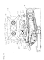
- Fig. 2 is a perspective view showing a print unit and a packing unit of Fig. 1;
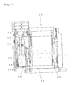
- Fig. 3 is a front view of the print unit of Fig.2;
- Fig. 4 is a partly enlarged front view of Fig. 3;
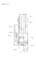
- Fig. 5 is an enlarged left side view of Fig. 4;
- Fig. 6 is an enlarged view in the vicinity of a tension roller of Fig. 5;
- Fig. 7 (a) is a plane view of the packing unit of Fig. 1 and 7(b) is a front view thereof;
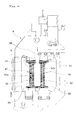
- Fig. 8 is a schematic illustrative explanatory view showing a conveying path of the packing sheet;
- Fig. 9 is a partly front view of the packing unit; and
- Fig. 10(a) is a partly enlarged view in the vicinity of a connection portion between a feed heat-seal portion and a vertical heat-seal portion of the embodiment of the present invention and 10(b) is a partly enlarged view in the vicinity of a connection portion between a feed heat-seal portion and a vertical heat-seal portion of a conventional heater roller.
- Hereinafter, embodiments according to the present invention will be described in accordance with the accompanying drawings.
- Fig. 1 shows a medicine packing apparatus according to the embodiment of the present invention. The medicine packing apparatus is provided with a
tablet feed portion 2 as the medicine feed means of the present invention and apowder feed portion 3 on the upper side of anapparatus body 1 and provided with a print unit (print means) 5 and apacking unit 8 on the lower side thereof. - The
tablet feed portion 2 is so constructed that when tablets to be packed into one package are previously manually put in each box formed like a lattice, a bottom plate of each box is sequentially opened to feed the tablets to thepacking unit 8. - The
powder feed portion 3 is so constructed that when powder is poured through ahopper 3, the powder is fed in an outer annular groove of a distribution dish not shown and the powder to be packed into one package is scraped out by a powder scraping apparatus not shown to feed the powder to thepacking unit 8. - The
print unit 5 is so constructed that as shown in Figs. 2 to 4 apacking sheet 7 wound on aroll 6 is rewound and printed with patient name, medicine name, usage and so on and then conveyed to thepacking unit 8. Thepacking sheet 7 is turned to a horizontal direction by aguide portion 9 and then ink of anink ribbon 11 is thermal transferred to the upper surface of thepacking sheet 7 by means of a thermal transfer potion (printer head) 10. The printedpacking sheet 7 passes through atension roller 12 and is turned upward by means of afirst roller 13. Then, thepacking sheet 7 is guided by a guide piece 14 to move upward and then turned obliquely downward by means of asecond roller 15 to advance toward thepacking unit 8. - The
ink ribbon 11, as shown in Fig. 3 and 4, is wound on afirst roll 16 and continuously rewound to asecond roll 17. Each of therolls holding plates 19 which are fixed on both ends of fourguide shafts 18 disposed around the rolls to constitute anink cartridge 20. On the end of anarm portion 21 extending from thelower guide shaft 18 is rotatably attached anauxiliary roller 22. - The
ink cartridge 20 is attached on aside plate 23 by fitting the inner cylinders 16a, 17a of therolls side plate 23 and then screwing nuts or so on the ends of shaft portions 24a, 24b. Driving a motor (ink ribbon conveying portion) not shown to rotate the shaft portion 24b allows theink ribbon 11 wound on thefirst roll 16 to be rewound on thesecond roll 17. Theink ribbon 11 is positioned between thethermal transfer portion 10 and theguide portion 9 and the slack of theink ribbon 11 is removed by anurged roller 25. The urgedroller 25 is rotatably attached on the end of anarm member 26 rotatably provided around asupport shaft 26a. Thearm member 26 is urged in a clockwise direction in Fig. 4 by aspring 27 one end of which is engaged with a attachment piece 43 attached on theapparatus body 1. - The tension roller 12 (moving means of the present invention), as shown in Figs. 5 and 6, is attached on the
support portion 29 extending from a descending and ascending table 28. The descending and ascending table 28 is provided with acover 30 for forming a path, through which thepacking sheet 7 passes, above thetension roller 12. The descending and ascending table 28 is provided so as to descend and ascend alongguide rails 31 uprightly provided at predetermined distance and is urged upward by aspring 32. A descending position of the descending and ascending table 28 is specified by detecting a magnet 44 built in the descending and ascending table 28 by means of a sensor 33 (position detecting means of the present invention) disposed aside. In order to make it possible to easily insert thepacking sheet 7, the descending and ascending table 28 is positioned at a lowest position by engaging an engagement recess portion 28a with a engagement piece 45 comprising a leaf spring attached on theside plate 23. - The
packing unit 8 is so constructed that thepacking sheet 7 printed by theprint unit 5 is folded into two or previously has been folded into two; thepacking sheet 7 is sealed in a longitudinal direction at predetermined intervals by means of aseal portion 34 that is a sealing means of the present invention to form a bag portion; the medicine fed from thetablet feed portion 2 or thepowder feed portion 3 is introduced into the bag formed; and remaining one side of thepacking sheet 7 is sealed. - The
seal portion 34 is attached in an oblique state corresponding to thepacking sheet 7 that advances obliquely downward. In theseal portion 34, as shown in Fig. 7, a pair offeed rollers 39 is intermittently driven via a directly driven gear 38a and a intermittently driven gear 38b by means of amotor 37 provided on the rear surface side of theside plate 23 of theapparatus body 1. Thus, thepacking sheet 7 sandwiched between thefeed rollers 39 is intermittently conveyed. - Referring further to Fig. 9, on the upstream side of the
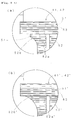
feed rollers 39 with respect to the feed direction of thepacking sheet 7, there are disposed a pair ofheater rollers restriction plate 50 for delivering thepacking sheet 7 to theheater rollers heater rollers seal portion 51 of circular plate and a vertical heat-seal portion 52 of thin rectangular plate on lower end of which aroller portion 55 having same diameter as that of the feed heat-seal portion 51 is integrally formed. The feed heat-seal portions motor 37 described above. In this embodiment, as themotor 37, a stepping motor is used so that change of pulse of the applied voltage allows conveying quantity to be adjusted. Between the heat-seal portions heater rollers packing sheet 7 are sealed. The vertical heat-seal portions 52 are driven to rotate by means of a rotation drive mechanism separately from the feed heat-seal portions 51, 51 (but, the rotation axes of the feed heat-seal portion 51 and the vertical heat-seal portion 52 are coincide with each other). The vertical heat-seal portions 52 are provided with a pair of heat-seal surfaces 52a opposite to each other. Since the vertical heat-seal portions 52 of bothheater rollers seal portions packing sheet 7 formed by the heat-seal surfaces 52a can be freely set. - Referring Fig. 10(a), construction in the vicinity of the upper end of the vertical heat-
seal portion 52 will be explained. On the feed heat-seal portion 51 and the vertical heat-seal portion 52,small grooves 53 extending in a feed direction of thepacking sheet 7 are formed at relatively narrow distances. At theheat seal surface 52a in the vicinity of the upper end of the vertical heat-seal portion 52 is formed a diameter enlarging portion 52b which extends in an arc-like shape outwardly toward the feed heat-seal portion 51. Further, between the diameter enlarging portion 52b and the end surface of the feed heat-seal portion 51 is formed a heat-seal introducing portion 54 of circular plate having a thin thickness. Referring to Fig. 10(b), in this kind of conventional heat rollers 41', 42', the diameter enlarging portion 52b' of theheat seal surface 52a' of the vertical heat-seal portion 52' has come into direct contact with the end surface of the feed heat-seal portion 51'. In such construction of Fig. 10(b), tension force act on thepacking sheet 7 in the vicinity of the contact portion of the feed heat-seal portion 51' and the vertical heat-seal portion 52' becomes non-uniform, which causes thepacking sheet 7 to shift with respect to the feed heat-seal portion 51' and the vertical heat-seal portion 52', resulting in wrinkle in thepacking sheet 7 after completion of seal. On the other hand, in the present invention, as the heat-seal introducing portion 54 of circular plate is formed between the diameter enlarging portion 52b and the end surface of the feed heat-seal portion 51 is formed as shown in Fig. 10(1), tension force act on thepacking sheet 7 in the vicinity of the contact portion of the feed heat-seal portion 51 and the vertical heat-seal portion 52 becomes uniform, which allows the packing sheet to be smoothly introduced between theheater rollers - Operation of the aforementioned medicine packing apparatus will be described.
- Before starting the packing process, a slack of the
packing sheet 7 may exist between theheater rollers packing unit 8 and thethermal transfer portion 10 of theprint unit 5. This slack is eliminated by the urgedtension roller 12 moving upward as shown in two-dots chain line in Fig. 8. in this case, the distance between theseal portion 34 and thethermal transfer portion 19 varies in accordance with the quantity of eliminated slack. - So, the
feed roller 39 is driven to rotate first, allowing the packing sheet to be conveyed. Thus, tension act on thepacking sheet 7 is increased, causing thetension roller 12 to descend against the urging force of thespring 32. When the sensor 33 (see Fig. 6) detects that thetension roller 12 descends until the descending position, the thermal transfer portion is heated to start print of thepacking sheet 7. Thus, thepacking sheet 7 can be printed as the tension act on thepacking sheet 7 is constant, allowing the dimension between theseal portion 34 and thethermal transfer portion 10 to be held at a predetermined value. - Subsequently, when the
packing sheet 7 with predetermined print is conveyed to thepacking unit 8, theheater rollers packing sheet 7 folded into two is sealed to make bags. Then, medicine are fed from thetablet feed portion 2 or thepowder feed portion 3 in accordance with a prescription data and introduced into thepacking sheet 7 via thepacking hopper 35. After that, rotation of theheater rollers packing sheet 7 is sealed to complete the packing of medicine to be packed into one package. - As described above, according to the medicine packing apparatus, when starting the packing process, print is surely commenced after descending the
tension roller 12 and detecting the descending position thereof by means of the sensor 33. Therefore, tension force act on thepacking sheet 7 becomes constant, allowing the dimension between theseal portion 34 and thethermal transfer portion 10 to be accurately held to a constant value, enabling to correctly print at the desired position. - In the aforementioned embodiments, although the
tension roller 12 is constituted so as to descend and ascend and the position thereof is detected so that the position thereof can be detected so that the dimension between the print position and the seal position of thepacking sheet 7 can be held to a predetermined value, it is also allowable that, for example, tension detecting means for detecting tension act on thepacking sheet 7 is provided and print by thethermal transfer portion 10 is commenced after the tension detected by the tension detection means becomes a predetermined value. As the tension detecting means, an arm or the like that comes into contact with thepacking sheet 7 and changes its rotation angel inn accordance with the difference of the tension of thepacking sheet 7 would be given but the constitution thereof would not be limited.
Claims (5)
- A medicine packing apparatus in which a packing sheet is printed with predetermined information by printing means, medicine is fed into the packing sheet by medicine feed means, and the packing sheet is sealed by seal means to pack the medicine by one package, wherein:the seal means is provided with conveyance portion for conveying the packing sheet;in the middle of a conveyance path from the print means to the seal means, there are provided moving means which comes into contact with the packing sheet and moves so that the tension of the packing sheet is held to be a constant value, andposition detecting means which detects a moved position of the moving means;whereby after the packing sheet is conveyed by the conveyance portion and the position detecting means detects a predetermined moved position, print by the print means is started.
- The medicine packing apparatus as in Claim 1, wherein the moving means comprises a roller which is rotatable and movable and urging means which urges the packing sheet with a constant force to eliminate a slack of the packing sheet.
- The medicine packing apparatus as in Claim 2, wherein the roller is a tension roller attached on a descending and ascending table which descends and ascends along a guide rail, the tension roller forcing up the packing sheet; and wherein the urging means is a spring for urging the descending and ascending table in an upward direction.
- The medicine packing apparatus as in Claim 3, wherein the position detecting means detects a descending position of the descending and ascending table.
- A medicine packing apparatus in which a packing sheet is printed with predetermined information by printing means, medicine is fed into the packing sheet by medicine feed means, and the packing sheet is sealed by seal means to pack the medicine by one package, wherein:the seal means is provided with conveyance portion for conveying the packing sheet;in the middle of a conveyance path from the print means to the seal means, there is provided tension detecting means which detects a tension act on the packing sheet;whereby after the packing sheet is conveyed by the conveyance portion and tension detecting means detects a predetermined tension of the packing sheet, print by the print means is started.
Applications Claiming Priority (3)
| Application Number | Priority Date | Filing Date | Title |
|---|---|---|---|
| JP2003099549 | 2003-04-02 | ||
| JP2003336456 | 2003-09-26 | ||
| PCT/JP2004/004250 WO2004089758A1 (en) | 2003-04-02 | 2004-03-26 | Medicine packaging device |
Publications (2)
| Publication Number | Publication Date |
|---|---|
| EP1612148A1 true EP1612148A1 (en) | 2006-01-04 |
| EP1612148A4 EP1612148A4 (en) | 2008-03-26 |
Family
ID=33161494
Family Applications (1)
| Application Number | Title | Priority Date | Filing Date |
|---|---|---|---|
| EP04723708A Withdrawn EP1612148A4 (en) | 2003-04-02 | 2004-03-26 | Medicine packaging device |
Country Status (6)
| Country | Link |
|---|---|
| US (1) | US7500337B2 (en) |
| EP (1) | EP1612148A4 (en) |
| JP (1) | JP4684105B2 (en) |
| KR (1) | KR101020277B1 (en) |
| TW (1) | TW200503925A (en) |
| WO (1) | WO2004089758A1 (en) |
Cited By (2)
| Publication number | Priority date | Publication date | Assignee | Title |
|---|---|---|---|---|
| EP2345580A4 (en) * | 2008-10-09 | 2013-10-16 | Yuyama Mfg Co Ltd | DRUG PACKAGING UNIT AND CORRESPONDING PACKAGING CONTROL METHOD |
| EP2392465A3 (en) * | 2010-06-03 | 2015-03-11 | JVM Co., Ltd. | Printer for automatic packing machine and method of controlling the same |
Families Citing this family (12)
| Publication number | Priority date | Publication date | Assignee | Title |
|---|---|---|---|---|
| US5771657A (en) * | 1996-05-07 | 1998-06-30 | Merck Medco Managed Care, Inc. | Automatic prescription filling, sorting and packaging system |
| JP5012806B2 (en) * | 2006-09-20 | 2012-08-29 | 株式会社湯山製作所 | Drug packaging device |
| KR101379990B1 (en) | 2007-10-23 | 2014-04-02 | 가부시키가이샤 유야마 세이사쿠쇼 | Drug delivery system, and drug delivery device |
| KR101240425B1 (en) * | 2010-11-02 | 2013-03-11 | 주식회사 오성메디 | Printing assembly for medicine packing apparatus and medicine packing apparatus including the same |
| KR101239891B1 (en) * | 2011-03-09 | 2013-03-06 | 주식회사 이오디지텍 | Packing method of automatic medicine packing machine |
| US9150119B2 (en) | 2013-03-15 | 2015-10-06 | Aesynt Incorporated | Apparatuses, systems, and methods for anticipating and delivering medications from a central pharmacy to a patient using a track based transport system |
| US9511945B2 (en) | 2012-10-12 | 2016-12-06 | Aesynt Incorporated | Apparatuses, systems, and methods for transporting medications from a central pharmacy to a patient in a healthcare facility |
| US20160009436A1 (en) * | 2014-07-14 | 2016-01-14 | Victor Basso | Machine for packing medical products and printing medical instructions for a nurse in a hospital environment |
| WO2019082858A1 (en) * | 2017-10-25 | 2019-05-02 | 株式会社湯山製作所 | Dispensing support system |
| IT201800010246A1 (en) * | 2018-11-12 | 2020-05-12 | Gd Spa | ARTICLE PACKAGING MACHINE |
| KR20220005129A (en) * | 2020-07-06 | 2022-01-13 | (주)제이브이엠 | Medicine information marking device |
| JP7834340B2 (en) * | 2022-12-14 | 2026-03-24 | 株式会社トーショー | packaging equipment |
Family Cites Families (24)
| Publication number | Priority date | Publication date | Assignee | Title |
|---|---|---|---|---|
| US3191356A (en) * | 1962-04-16 | 1965-06-29 | Weldotron Corp | Packaging apparatus |
| US3326436A (en) * | 1966-08-19 | 1967-06-20 | William F Huck | Web registering and tension control system for multi-unit presses |
| CA928732A (en) | 1968-08-21 | 1973-06-19 | H. Treff Ernest | Automatic web tension and register control |
| US3556510A (en) * | 1968-08-21 | 1971-01-19 | Harris Intertype Corp | Automatic web tension and register control |
| US5097652A (en) * | 1989-08-10 | 1992-03-24 | Sanyo Electric Co., Ltd. | Drug packing apparatus |
| JP2538350B2 (en) * | 1989-09-08 | 1996-09-25 | 三洋電機株式会社 | Medicine package extractor of medicine packaging machine |
| JP2579010B2 (en) | 1989-12-22 | 1997-02-05 | 正二 湯山 | How to print medicine packaging paper |
| US5371521A (en) * | 1992-04-01 | 1994-12-06 | Automated Packaging Systems, Inc. | Packaging machine with thermal imprinter and method |
| US5405487A (en) * | 1992-06-30 | 1995-04-11 | Cms Gilbreth Packaging Systems, Inc. | Apparatus and method for applying labels onto small cylindrical articles and web and adhesive delivery mechanism |
| JP3199136B2 (en) * | 1992-11-02 | 2001-08-13 | 株式会社イシダ | Packaging material transfer device |
| US5468080A (en) * | 1993-03-25 | 1995-11-21 | Jones; William B. | Poly bag printer for packaging machine |
| JP3694331B2 (en) * | 1994-03-25 | 2005-09-14 | 株式会社サトー | Ink ribbon cassette device in thermal transfer printer |
| JP3402869B2 (en) * | 1995-08-23 | 2003-05-06 | 三洋電機株式会社 | Solid pharmaceutical packaging equipment |
| US6659006B2 (en) * | 1995-08-30 | 2003-12-09 | Goss Graphic Systems Inc. | Tension control device for a printing press |
| US5846005A (en) * | 1996-09-09 | 1998-12-08 | Primera Technology, Inc. | Label printer with cutter attachment |
| JP2937141B2 (en) * | 1996-09-20 | 1999-08-23 | ソニー株式会社 | Continuous feeder and method for strip material |
| JP2819283B2 (en) * | 1996-12-24 | 1998-10-30 | 株式会社東京機械製作所 | Continuous paper running tension control device |
| US6067103A (en) * | 1997-03-07 | 2000-05-23 | J.I.T. Technologies, Inc. | Apparatus and process for variable image printing on tape |
| AU8593598A (en) * | 1997-07-28 | 1999-02-16 | Ranpak Corp. | Cushioning conversion machine with power infeed |
| JP3032763B1 (en) * | 1999-06-17 | 2000-04-17 | 株式会社東京機械製作所 | Paper feed unit with web paper running tension control device for rotary press |
| US6470648B1 (en) * | 2000-06-22 | 2002-10-29 | Advanced Poly-Packaging, Inc. | Packaging sealer printer |
| JP3564409B2 (en) * | 2001-02-23 | 2004-09-08 | 三菱重工業株式会社 | Control method and control device at start of operation of rotary printing press |
| CN2470325Y (en) | 2001-04-10 | 2002-01-09 | (湖北)三九长江实业集团武汉轻工业机械厂 | Retraction coil tension controller of film compounding machine |
| US6543201B2 (en) * | 2001-09-07 | 2003-04-08 | Automated Packaging Systems, Inc. | Individual package bagger and process |
-
2004
- 2004-03-26 WO PCT/JP2004/004250 patent/WO2004089758A1/en not_active Ceased
- 2004-03-26 JP JP2005505197A patent/JP4684105B2/en not_active Expired - Fee Related
- 2004-03-26 KR KR1020057017692A patent/KR101020277B1/en not_active Expired - Fee Related
- 2004-03-26 US US10/551,128 patent/US7500337B2/en not_active Expired - Fee Related
- 2004-03-26 EP EP04723708A patent/EP1612148A4/en not_active Withdrawn
- 2004-03-31 TW TW093108877A patent/TW200503925A/en unknown
Cited By (2)
| Publication number | Priority date | Publication date | Assignee | Title |
|---|---|---|---|---|
| EP2345580A4 (en) * | 2008-10-09 | 2013-10-16 | Yuyama Mfg Co Ltd | DRUG PACKAGING UNIT AND CORRESPONDING PACKAGING CONTROL METHOD |
| EP2392465A3 (en) * | 2010-06-03 | 2015-03-11 | JVM Co., Ltd. | Printer for automatic packing machine and method of controlling the same |
Also Published As
| Publication number | Publication date |
|---|---|
| WO2004089758A1 (en) | 2004-10-21 |
| EP1612148A4 (en) | 2008-03-26 |
| JPWO2004089758A1 (en) | 2006-07-06 |
| KR20050120655A (en) | 2005-12-22 |
| US7500337B2 (en) | 2009-03-10 |
| JP4684105B2 (en) | 2011-05-18 |
| US20060254210A1 (en) | 2006-11-16 |
| TW200503925A (en) | 2005-02-01 |
| KR101020277B1 (en) | 2011-03-07 |
Similar Documents
| Publication | Publication Date | Title |
|---|---|---|
| US7500337B2 (en) | Medicine packaging device | |
| CA2428246C (en) | Continuous strip bag feeder and loader with integrated printer assembly | |
| US5468080A (en) | Poly bag printer for packaging machine | |
| KR100521720B1 (en) | a package paper thermal printer of pill packing machine | |
| TWI598245B (en) | Recycling method of medicine packaging device, ink ribbon roll and ink supply core | |
| US4559755A (en) | Device for flexographic printing on a strip of packing material in packaging machines, particularly for blister packs | |
| US20180186484A1 (en) | Medicine Packaging Apparatus | |
| CN111542477B (en) | Method and apparatus for applying labels to cigarette packages | |
| JPS5933162A (en) | Rotary head type coining marking device | |
| JP2026040758A (en) | Fixed pitch printing system | |
| JPH03275427A (en) | End seal positioning method and device for pillow packaging machine | |
| CN100467352C (en) | Pharmaceutical packaging device | |
| JP3969495B2 (en) | Cover film constant tension feeding device for PTP machine | |
| JP2015048136A (en) | Pocket part formation device of blister pack and packaging device | |
| WO2018030096A1 (en) | Packaging apparatus | |
| KR101460506B1 (en) | Packing module of drug packing apparatus | |
| IT202100004106A1 (en) | PRINTING UNIT FOR PACKAGING EQUIPMENT, APPARATUS AND METHOD FOR THE PRODUCTION OF A SINGLE-DOSE SEALED PACK. | |
| JPS62287805A (en) | Molding sealing device for vessel with spout | |
| JP2000033918A (en) | Packaging machine | |
| JP4462095B2 (en) | Meander adjustment feeder device | |
| JP2026068098A (en) | Blister packaging machine | |
| JP3000229B2 (en) | Simple packaging machine | |
| JPH079644Y2 (en) | Medicine bag printer | |
| JP3099118B2 (en) | Packaging method and packaging device | |
| JPS6140643Y2 (en) |
Legal Events
| Date | Code | Title | Description |
|---|---|---|---|
| PUAI | Public reference made under article 153(3) epc to a published international application that has entered the european phase |
Free format text: ORIGINAL CODE: 0009012 |
|
| 17P | Request for examination filed |
Effective date: 20050928 |
|
| AK | Designated contracting states |
Kind code of ref document: A1 Designated state(s): AT BE BG CH CY CZ DE DK EE ES FI FR GB GR HU IE IT LI LU MC NL PL PT RO SE SI SK TR |
|
| AX | Request for extension of the european patent |
Extension state: AL LT LV MK |
|
| DAX | Request for extension of the european patent (deleted) | ||
| A4 | Supplementary search report drawn up and despatched |
Effective date: 20080227 |
|
| 17Q | First examination report despatched |
Effective date: 20090220 |
|
| GRAP | Despatch of communication of intention to grant a patent |
Free format text: ORIGINAL CODE: EPIDOSNIGR1 |
|
| STAA | Information on the status of an ep patent application or granted ep patent |
Free format text: STATUS: THE APPLICATION IS DEEMED TO BE WITHDRAWN |
|
| 18D | Application deemed to be withdrawn |
Effective date: 20110804 |