EP1612013B1 - Rotary cutter and rotary cutting apparatus provided with the rotary cutter - Google Patents
Rotary cutter and rotary cutting apparatus provided with the rotary cutter Download PDFInfo
- Publication number
- EP1612013B1 EP1612013B1 EP20050445039 EP05445039A EP1612013B1 EP 1612013 B1 EP1612013 B1 EP 1612013B1 EP 20050445039 EP20050445039 EP 20050445039 EP 05445039 A EP05445039 A EP 05445039A EP 1612013 B1 EP1612013 B1 EP 1612013B1
- Authority
- EP
- European Patent Office
- Prior art keywords
- mantle
- shaft
- rotary cutter
- rotary
- cutting apparatus
- Prior art date
- Legal status (The legal status is an assumption and is not a legal conclusion. Google has not performed a legal analysis and makes no representation as to the accuracy of the status listed.)
- Expired - Lifetime
Links
Images

Classifications
-
- B—PERFORMING OPERATIONS; TRANSPORTING
- B26—HAND CUTTING TOOLS; CUTTING; SEVERING
- B26D—CUTTING; DETAILS COMMON TO MACHINES FOR PERFORATING, PUNCHING, CUTTING-OUT, STAMPING-OUT OR SEVERING
- B26D1/00—Cutting through work characterised by the nature or movement of the cutting member or particular materials not otherwise provided for; Apparatus or machines therefor; Cutting members therefor
- B26D1/01—Cutting through work characterised by the nature or movement of the cutting member or particular materials not otherwise provided for; Apparatus or machines therefor; Cutting members therefor involving a cutting member which does not travel with the work
- B26D1/12—Cutting through work characterised by the nature or movement of the cutting member or particular materials not otherwise provided for; Apparatus or machines therefor; Cutting members therefor involving a cutting member which does not travel with the work having a cutting member moving about an axis
- B26D1/25—Cutting through work characterised by the nature or movement of the cutting member or particular materials not otherwise provided for; Apparatus or machines therefor; Cutting members therefor involving a cutting member which does not travel with the work having a cutting member moving about an axis with a non-circular cutting member
- B26D1/34—Cutting through work characterised by the nature or movement of the cutting member or particular materials not otherwise provided for; Apparatus or machines therefor; Cutting members therefor involving a cutting member which does not travel with the work having a cutting member moving about an axis with a non-circular cutting member moving about an axis parallel to the line of cut
- B26D1/40—Cutting through work characterised by the nature or movement of the cutting member or particular materials not otherwise provided for; Apparatus or machines therefor; Cutting members therefor involving a cutting member which does not travel with the work having a cutting member moving about an axis with a non-circular cutting member moving about an axis parallel to the line of cut and coacting with a rotary member
-
- B—PERFORMING OPERATIONS; TRANSPORTING
- B26—HAND CUTTING TOOLS; CUTTING; SEVERING
- B26D—CUTTING; DETAILS COMMON TO MACHINES FOR PERFORATING, PUNCHING, CUTTING-OUT, STAMPING-OUT OR SEVERING
- B26D7/00—Details of apparatus for cutting, cutting-out, stamping-out, punching, perforating, or severing by means other than cutting
- B26D7/26—Means for mounting or adjusting the cutting member; Means for adjusting the stroke of the cutting member
-
- B—PERFORMING OPERATIONS; TRANSPORTING
- B26—HAND CUTTING TOOLS; CUTTING; SEVERING
- B26D—CUTTING; DETAILS COMMON TO MACHINES FOR PERFORATING, PUNCHING, CUTTING-OUT, STAMPING-OUT OR SEVERING
- B26D7/00—Details of apparatus for cutting, cutting-out, stamping-out, punching, perforating, or severing by means other than cutting
- B26D7/26—Means for mounting or adjusting the cutting member; Means for adjusting the stroke of the cutting member
- B26D7/2614—Means for mounting the cutting member
-
- B—PERFORMING OPERATIONS; TRANSPORTING
- B26—HAND CUTTING TOOLS; CUTTING; SEVERING
- B26D—CUTTING; DETAILS COMMON TO MACHINES FOR PERFORATING, PUNCHING, CUTTING-OUT, STAMPING-OUT OR SEVERING
- B26D7/00—Details of apparatus for cutting, cutting-out, stamping-out, punching, perforating, or severing by means other than cutting
- B26D7/26—Means for mounting or adjusting the cutting member; Means for adjusting the stroke of the cutting member
- B26D7/2628—Means for adjusting the position of the cutting member
- B26D7/265—Journals, bearings or supports for positioning rollers or cylinders relatively to each other
-
- B—PERFORMING OPERATIONS; TRANSPORTING
- B26—HAND CUTTING TOOLS; CUTTING; SEVERING
- B26F—PERFORATING; PUNCHING; CUTTING-OUT; STAMPING-OUT; SEVERING BY MEANS OTHER THAN CUTTING
- B26F1/00—Perforating; Punching; Cutting-out; Stamping-out; Apparatus therefor
- B26F1/38—Cutting-out; Stamping-out
-
- B—PERFORMING OPERATIONS; TRANSPORTING
- B26—HAND CUTTING TOOLS; CUTTING; SEVERING
- B26F—PERFORATING; PUNCHING; CUTTING-OUT; STAMPING-OUT; SEVERING BY MEANS OTHER THAN CUTTING
- B26F1/00—Perforating; Punching; Cutting-out; Stamping-out; Apparatus therefor
- B26F1/38—Cutting-out; Stamping-out
- B26F1/384—Cutting-out; Stamping-out using rotating drums
-
- B—PERFORMING OPERATIONS; TRANSPORTING
- B26—HAND CUTTING TOOLS; CUTTING; SEVERING
- B26F—PERFORATING; PUNCHING; CUTTING-OUT; STAMPING-OUT; SEVERING BY MEANS OTHER THAN CUTTING
- B26F1/00—Perforating; Punching; Cutting-out; Stamping-out; Apparatus therefor
- B26F1/38—Cutting-out; Stamping-out
- B26F1/44—Cutters therefor; Dies therefor
-
- B—PERFORMING OPERATIONS; TRANSPORTING
- B26—HAND CUTTING TOOLS; CUTTING; SEVERING
- B26D—CUTTING; DETAILS COMMON TO MACHINES FOR PERFORATING, PUNCHING, CUTTING-OUT, STAMPING-OUT OR SEVERING
- B26D1/00—Cutting through work characterised by the nature or movement of the cutting member or particular materials not otherwise provided for; Apparatus or machines therefor; Cutting members therefor
- B26D1/56—Cutting through work characterised by the nature or movement of the cutting member or particular materials not otherwise provided for; Apparatus or machines therefor; Cutting members therefor involving a cutting member which travels with the work otherwise than in the direction of the cut, i.e. flying cutter
- B26D1/62—Cutting through work characterised by the nature or movement of the cutting member or particular materials not otherwise provided for; Apparatus or machines therefor; Cutting members therefor involving a cutting member which travels with the work otherwise than in the direction of the cut, i.e. flying cutter and is rotating about an axis parallel to the line of cut, e.g. mounted on a rotary cylinder
- B26D1/626—Cutting through work characterised by the nature or movement of the cutting member or particular materials not otherwise provided for; Apparatus or machines therefor; Cutting members therefor involving a cutting member which travels with the work otherwise than in the direction of the cut, i.e. flying cutter and is rotating about an axis parallel to the line of cut, e.g. mounted on a rotary cylinder for thin material, e.g. for sheets, strips or the like
-
- Y—GENERAL TAGGING OF NEW TECHNOLOGICAL DEVELOPMENTS; GENERAL TAGGING OF CROSS-SECTIONAL TECHNOLOGIES SPANNING OVER SEVERAL SECTIONS OF THE IPC; TECHNICAL SUBJECTS COVERED BY FORMER USPC CROSS-REFERENCE ART COLLECTIONS [XRACs] AND DIGESTS
- Y10—TECHNICAL SUBJECTS COVERED BY FORMER USPC
- Y10T—TECHNICAL SUBJECTS COVERED BY FORMER US CLASSIFICATION
- Y10T83/00—Cutting
- Y10T83/465—Cutting motion of tool has component in direction of moving work
- Y10T83/4766—Orbital motion of cutting blade
- Y10T83/4795—Rotary tool
-
- Y—GENERAL TAGGING OF NEW TECHNOLOGICAL DEVELOPMENTS; GENERAL TAGGING OF CROSS-SECTIONAL TECHNOLOGIES SPANNING OVER SEVERAL SECTIONS OF THE IPC; TECHNICAL SUBJECTS COVERED BY FORMER USPC CROSS-REFERENCE ART COLLECTIONS [XRACs] AND DIGESTS
- Y10—TECHNICAL SUBJECTS COVERED BY FORMER USPC
- Y10T—TECHNICAL SUBJECTS COVERED BY FORMER US CLASSIFICATION
- Y10T83/00—Cutting
- Y10T83/465—Cutting motion of tool has component in direction of moving work
- Y10T83/4766—Orbital motion of cutting blade
- Y10T83/4795—Rotary tool
- Y10T83/483—With cooperating rotary cutter or backup
-
- Y—GENERAL TAGGING OF NEW TECHNOLOGICAL DEVELOPMENTS; GENERAL TAGGING OF CROSS-SECTIONAL TECHNOLOGIES SPANNING OVER SEVERAL SECTIONS OF THE IPC; TECHNICAL SUBJECTS COVERED BY FORMER USPC CROSS-REFERENCE ART COLLECTIONS [XRACs] AND DIGESTS
- Y10—TECHNICAL SUBJECTS COVERED BY FORMER USPC
- Y10T—TECHNICAL SUBJECTS COVERED BY FORMER US CLASSIFICATION
- Y10T83/00—Cutting
- Y10T83/465—Cutting motion of tool has component in direction of moving work
- Y10T83/4766—Orbital motion of cutting blade
- Y10T83/4795—Rotary tool
- Y10T83/483—With cooperating rotary cutter or backup
- Y10T83/4838—With anvil backup
-
- Y—GENERAL TAGGING OF NEW TECHNOLOGICAL DEVELOPMENTS; GENERAL TAGGING OF CROSS-SECTIONAL TECHNOLOGIES SPANNING OVER SEVERAL SECTIONS OF THE IPC; TECHNICAL SUBJECTS COVERED BY FORMER USPC CROSS-REFERENCE ART COLLECTIONS [XRACs] AND DIGESTS
- Y10—TECHNICAL SUBJECTS COVERED BY FORMER USPC
- Y10T—TECHNICAL SUBJECTS COVERED BY FORMER US CLASSIFICATION
- Y10T83/00—Cutting
- Y10T83/768—Rotatable disc tool pair or tool and carrier
- Y10T83/7809—Tool pair comprises rotatable tools
- Y10T83/7851—Tool pair comprises disc and cylindrical anvil
-
- Y—GENERAL TAGGING OF NEW TECHNOLOGICAL DEVELOPMENTS; GENERAL TAGGING OF CROSS-SECTIONAL TECHNOLOGIES SPANNING OVER SEVERAL SECTIONS OF THE IPC; TECHNICAL SUBJECTS COVERED BY FORMER USPC CROSS-REFERENCE ART COLLECTIONS [XRACs] AND DIGESTS
- Y10—TECHNICAL SUBJECTS COVERED BY FORMER USPC
- Y10T—TECHNICAL SUBJECTS COVERED BY FORMER US CLASSIFICATION
- Y10T83/00—Cutting
- Y10T83/929—Tool or tool with support
- Y10T83/9309—Anvil
- Y10T83/9312—Rotatable type
-
- Y—GENERAL TAGGING OF NEW TECHNOLOGICAL DEVELOPMENTS; GENERAL TAGGING OF CROSS-SECTIONAL TECHNOLOGIES SPANNING OVER SEVERAL SECTIONS OF THE IPC; TECHNICAL SUBJECTS COVERED BY FORMER USPC CROSS-REFERENCE ART COLLECTIONS [XRACs] AND DIGESTS
- Y10—TECHNICAL SUBJECTS COVERED BY FORMER USPC
- Y10T—TECHNICAL SUBJECTS COVERED BY FORMER US CLASSIFICATION
- Y10T83/00—Cutting
- Y10T83/929—Tool or tool with support
- Y10T83/9372—Rotatable type
- Y10T83/9377—Mounting of tool about rod-type shaft
-
- Y—GENERAL TAGGING OF NEW TECHNOLOGICAL DEVELOPMENTS; GENERAL TAGGING OF CROSS-SECTIONAL TECHNOLOGIES SPANNING OVER SEVERAL SECTIONS OF THE IPC; TECHNICAL SUBJECTS COVERED BY FORMER USPC CROSS-REFERENCE ART COLLECTIONS [XRACs] AND DIGESTS
- Y10—TECHNICAL SUBJECTS COVERED BY FORMER USPC
- Y10T—TECHNICAL SUBJECTS COVERED BY FORMER US CLASSIFICATION
- Y10T83/00—Cutting
- Y10T83/929—Tool or tool with support
- Y10T83/9457—Joint or connection
-
- Y—GENERAL TAGGING OF NEW TECHNOLOGICAL DEVELOPMENTS; GENERAL TAGGING OF CROSS-SECTIONAL TECHNOLOGIES SPANNING OVER SEVERAL SECTIONS OF THE IPC; TECHNICAL SUBJECTS COVERED BY FORMER USPC CROSS-REFERENCE ART COLLECTIONS [XRACs] AND DIGESTS
- Y10—TECHNICAL SUBJECTS COVERED BY FORMER USPC
- Y10T—TECHNICAL SUBJECTS COVERED BY FORMER US CLASSIFICATION
- Y10T83/00—Cutting
- Y10T83/929—Tool or tool with support
- Y10T83/9457—Joint or connection
- Y10T83/9464—For rotary tool
Definitions
- the present invention relates to a rotary cutter for a rotary cutting apparatus, comprising a shaft and a mantle, the mantle having at least one cutting member.
- the invention also relates to a rotary cutting apparatus comprising a frame part, an anvil and such a rotary cutter.
- US-A-4 770 078 discloses in a discussion of the prior art ( Figs. 1-3 ) a one piece rotary cutter, which has to be removed from the frame when maintenance is needed. In order to allow the machine to be used during maintenance, a further rotary cutter including its static (stationary) shaft must always be accessible.
- US-A-4 770 078 suggests to divide the rotary cutter into a rotatable shaft and a mantle.
- the mantle is connected to the rotatable shaft by means of pneumatic pressure.
- a drawback with this kind of rotary cutter is that it is difficult to index the rotary cutter relative to the anvil.
- Another drawback is the lack of support of the rotary cutter on the axial side thereof opposite to the driven side.
- An object of the invention is to improve the adjustment possibilities of the rotary cutter. It is a further object to allow maintenance to be performed at a reduced cost and to be able to dismantle the rotary cutter in a simplified manner.
- a rotary cutter and a rotary cutting apparatus of the initially defined kind wherein the shaft is adapted to be rigidly mounted in a frame part, said shaft is divided into a first and a second shaft portions, the mantle having an axial extension and opposite axial ends, wherein said mantle is adapted to be supported by the first shaft portion and connected to the power source in the region of one of the ends of said mantle, and wherein said mantle is adapted to be supported by the second shaft portion in the region of the opposite end.
- the mantle is rotatably arranged relative to the shaft and removable therefrom.
- indexing of the mantle relative to the shaft is made easier, since the mantle can be rotated relative to the static shaft.
- it is only necessary to perform maintenance of the mantle i.e. the existing shaft can be used together with another mantle such that the production can be continued while maintenance is performed on the worn mantle.
- the mantle is adapted to be connected to a power source for creating a rotational movement of the mantle.
- bearings are provided between the mantle and the shaft.
- a controlled positional and relative rotational relationship between the static shaft and the mantle is achieved.
- a power transmission means is provided for transmitting the rotational movement to said mantle.
- the frame part of the rotary cutting apparatus further comprises a fastening means for said shaft and a power transmission connection means for said mantle.
- Figure 1 shows a rotary cutting apparatus 2, comprising a rotary cutter 4 and an anvil roll 6.
- the rotary cutter 4 comprises a divided static (non-rotary) shaft, comprising shaft portions or members 8a, 8b, each shaft member being rigidly connected to a respective frame part 10 by means of screws 12.
- a drive axle 14 associated with a not-shown power source extends through the shaft member 8a for transmitting a rotational movement to a tool in the form of a mantle 16 via an intermediate transmission member 18a which is rotatably mounted on an outer periphery of the shaft member 8a.
- the rotary motion is transmitted from the axle 14 to the member 18a via teeth.
- the rotational movement is further transmitted to a rotational support 18b.
- Cylindrical bearings 19 are provided between the shaft members 8a, 8b and the intermediate transmission members 18a, 18b, respectively, for centering the mantle 16 relative to the shaft members 8a, 8b.
- the frame parts 10 are secured to the rest of a stationary frame by means of suitable, not-shown fastening means.
- the mantle 16 is provided with at least one cutting member.
- the frame parts 10 are unsecured from the not-shown rest of the frame such that the static shaft members 8a, 8b, plus the transmission members 18a, 18b, can be pulled axially out from the mantle 16.
- the mantle 16 is taken away and maintenance can thus be performed.
- Another mantle 16 is mounted in place of the removed one, and the rotary cutting device can be utilised without long stoppage.
- Figure 2 shows another embodiment of a rotary cutting apparatus and a rotary cutter 4.
- the cross-section is such that the cutting member has been omitted.
- the drive axle 14 transmits rotational movement directly to the mantle 16 via a coupling member 22 which is received in a recess of the mantle.
- the static shaft is divided into two shaft members or portions 8a, 8 connected to the respective frame parts 10 on either side of the mantle 16.
- the mantle 16 is centered relative to the shaft members 8a, 8b and the driving axle 14 by means of conical bearings 24.
- the shaft member 8b is unsecured from the frame parts 10 and then the mantle 16 is released axially from the shaft member 8a.
- the mantle 16 may be made of a multiphase material, such as steel, cemented carbide or cermet (hard phase bonded by a metal).
Landscapes
- Life Sciences & Earth Sciences (AREA)
- Forests & Forestry (AREA)
- Engineering & Computer Science (AREA)
- Mechanical Engineering (AREA)
- Crushing And Pulverization Processes (AREA)
- Perforating, Stamping-Out Or Severing By Means Other Than Cutting (AREA)
- Crushing And Grinding (AREA)
- Details Of Cutting Devices (AREA)
- Harvester Elements (AREA)
Abstract
Description
- The present invention relates to a rotary cutter for a rotary cutting apparatus, comprising a shaft and a mantle, the mantle having at least one cutting member.
- The invention also relates to a rotary cutting apparatus comprising a frame part, an anvil and such a rotary cutter.
-
US-A-4 770 078 discloses in a discussion of the prior art (Figs. 1-3 ) a one piece rotary cutter, which has to be removed from the frame when maintenance is needed. In order to allow the machine to be used during maintenance, a further rotary cutter including its static (stationary) shaft must always be accessible. - In order to overcome that problem,
US-A-4 770 078 suggests to divide the rotary cutter into a rotatable shaft and a mantle. The mantle is connected to the rotatable shaft by means of pneumatic pressure. A drawback with this kind of rotary cutter is that it is difficult to index the rotary cutter relative to the anvil. Another drawback is the lack of support of the rotary cutter on the axial side thereof opposite to the driven side. -
DE 89 00 516 upon which the preamble of claim 1 is based; discloses a rotary cutter comprising a shaft and a mantle wherein the shaft is stationary and the mantle is rotatably arranged relative to the shaft. - An object of the invention is to improve the adjustment possibilities of the rotary cutter. It is a further object to allow maintenance to be performed at a reduced cost and to be able to dismantle the rotary cutter in a simplified manner.
- This has been achieved by a rotary cutter and a rotary cutting apparatus of the initially defined kind, wherein the shaft is adapted to be rigidly mounted in a frame part, said shaft is divided into a first and a second shaft portions, the mantle having an axial extension and opposite axial ends, wherein said mantle is adapted to be supported by the first shaft portion and connected to the power source in the region of one of the ends of said mantle, and wherein said mantle is adapted to be supported by the second shaft portion in the region of the opposite end. The mantle is rotatably arranged relative to the shaft and removable therefrom. Hereby, indexing of the mantle relative to the shaft is made easier, since the mantle can be rotated relative to the static shaft. Furthermore, it is only necessary to perform maintenance of the mantle, i.e. the existing shaft can be used together with another mantle such that the production can be continued while maintenance is performed on the worn mantle.
- The mantle is adapted to be connected to a power source for creating a rotational movement of the mantle.
- Preferably bearings are provided between the mantle and the shaft. Hereby, a controlled positional and relative rotational relationship between the static shaft and the mantle is achieved.
- Suitably, a power transmission means is provided for transmitting the rotational movement to said mantle.
- Advantageously, the frame part of the rotary cutting apparatus further comprises a fastening means for said shaft and a power transmission connection means for said mantle.
- In the following, preferred embodiments of the invention will be described in greater detail by reference to the accompanying drawings, in which
-
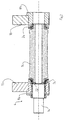
Figure 1 illustrates a rotary cutting apparatus comprising an anvil and a rotary cutter according to a first embodiment of the invention, shown in longitudinal section; -
Figure 2 is a longitudinal sectional view of another embodiment of the rotary cutter. -
Figure 1 shows a rotary cutting apparatus 2, comprising a rotary cutter 4 and an anvil roll 6. The rotary cutter 4 comprises a divided static (non-rotary) shaft, comprising shaft portions ormembers respective frame part 10 by means ofscrews 12. Adrive axle 14 associated with a not-shown power source extends through theshaft member 8a for transmitting a rotational movement to a tool in the form of amantle 16 via anintermediate transmission member 18a which is rotatably mounted on an outer periphery of theshaft member 8a. The rotary motion is transmitted from theaxle 14 to themember 18a via teeth. The rotational movement is further transmitted to a rotational support 18b.Cylindrical bearings 19 are provided between theshaft members intermediate transmission members 18a, 18b, respectively, for centering themantle 16 relative to theshaft members frame parts 10 are secured to the rest of a stationary frame by means of suitable, not-shown fastening means. Themantle 16 is provided with at least one cutting member. - During disassembly, the
frame parts 10 are unsecured from the not-shown rest of the frame such that thestatic shaft members transmission members 18a, 18b, can be pulled axially out from themantle 16. Themantle 16 is taken away and maintenance can thus be performed. Anothermantle 16 is mounted in place of the removed one, and the rotary cutting device can be utilised without long stoppage. - Of course, it may be enough to remove only one (either) of the
static shaft members -
Figure 2 shows another embodiment of a rotary cutting apparatus and a rotary cutter 4. In this case, the cross-section is such that the cutting member has been omitted. Thedrive axle 14 transmits rotational movement directly to themantle 16 via acoupling member 22 which is received in a recess of the mantle. The static shaft is divided into two shaft members orportions 8a, 8 connected to therespective frame parts 10 on either side of themantle 16. Themantle 16 is centered relative to theshaft members axle 14 by means ofconical bearings 24. - For maintenance purposes, the
shaft member 8b is unsecured from theframe parts 10 and then themantle 16 is released axially from theshaft member 8a. - The
mantle 16 may be made of a multiphase material, such as steel, cemented carbide or cermet (hard phase bonded by a metal).
Claims (5)
- A rotary cutter for a rotary cutting apparatus, comprising a mantle (16), the mantle having at least one cutting member, characterised in the rotary cutter further comprising a first and a second shaft member (8a, 8b) spaced apart along an axis of rotation of the mantle (16), said shaft members adapted to be rigidly mounted in a respective frame part (10), wherein the mantle (16) is rotatably arranged relative to the shaft members (8a, 8b) and removable therefrom, the mantle (16) having an axial extension and opposite axial ends, wherein said mantle (16) is adapted to be supported by the first shaft member (8a) and connected to said power source in the region of one of the ends of said mantle (16), wherein said mantle is adapted to be supported by the second shaft member (8b) in the region of the opposite end.
- A rotary cutter according to claim 1, wherein the mantle (16) is adapted to be connected to a power source for creating a rotational movement of the mantle.
- A rotary cutter according to claim 1 or 2, wherein bearings are provided between the mantle (16) and the shaft members (8a, 8b).
- A rotary cutter according to claim 1 or 2, wherein a power transmission means (18a, 18b; 22) is provided for transmitting the rotational movement to said mantle (16).
- A rotary cutting apparatus comprising a frame part (10), an anvil (6) and a rotary cutter (4) according to any one of the preceding claims, said frame part (10) being provided with a fastening means (12) for said shaft members (8a, 8b).
Applications Claiming Priority (1)
| Application Number | Priority Date | Filing Date | Title |
|---|---|---|---|
| SE0401734A SE527838C2 (en) | 2004-07-02 | 2004-07-02 | A rotary knife and a rotary knife device provided with such a rotary knife |
Publications (2)
| Publication Number | Publication Date |
|---|---|
| EP1612013A1 EP1612013A1 (en) | 2006-01-04 |
| EP1612013B1 true EP1612013B1 (en) | 2011-11-16 |
Family
ID=32733758
Family Applications (1)
| Application Number | Title | Priority Date | Filing Date |
|---|---|---|---|
| EP20050445039 Expired - Lifetime EP1612013B1 (en) | 2004-07-02 | 2005-05-30 | Rotary cutter and rotary cutting apparatus provided with the rotary cutter |
Country Status (8)
| Country | Link |
|---|---|
| US (3) | US20060070505A1 (en) |
| EP (1) | EP1612013B1 (en) |
| JP (1) | JP4903402B2 (en) |
| KR (1) | KR101273306B1 (en) |
| CN (2) | CN100594105C (en) |
| AT (1) | ATE533602T1 (en) |
| SE (1) | SE527838C2 (en) |
| WO (1) | WO2006004478A1 (en) |
Families Citing this family (12)
| Publication number | Priority date | Publication date | Assignee | Title |
|---|---|---|---|---|
| SE527886C2 (en) * | 2004-07-02 | 2006-07-04 | Sandvik Intellectual Property | A rotary knife, a support roller and a rotary knife device |
| DE102007016451A1 (en) * | 2007-03-30 | 2008-10-02 | Wilhelm Aichele | A rotary knife |
| JP5372650B2 (en) * | 2009-08-06 | 2013-12-18 | 三菱重工印刷紙工機械株式会社 | Rotary die cutter blade mounting base installation device |
| US8272923B2 (en) | 2009-08-13 | 2012-09-25 | The Procter & Gamble Company | Methods and apparatuses for anvil reconditioning |
| US9902083B2 (en) | 2010-09-30 | 2018-02-27 | The Procter & Gamble Company | Absorbent article substrate trim material removal process and apparatus |
| WO2012141558A1 (en) * | 2011-04-14 | 2012-10-18 | Ha Yong-Gan | Cone-shaped crusher |
| CN103029172A (en) * | 2011-09-14 | 2013-04-10 | 苏州安洁科技股份有限公司 | Long-sized cylinder knife die cutting mould |
| CN103128795A (en) * | 2011-12-05 | 2013-06-05 | 苏州源德福科技有限公司 | Die-cutting device |
| CN104608181A (en) * | 2014-12-23 | 2015-05-13 | 苏州源德福科技有限公司 | Circular knife extracting die cutting waste |
| JP6148418B1 (en) * | 2016-02-24 | 2017-06-14 | 日本タングステン株式会社 | Roll for rotary cutter and rotary cutter |
| CN106827025A (en) * | 2017-03-28 | 2017-06-13 | 靳世科 | Chopping block mechanism and punching machine |
| CN108247716A (en) * | 2018-03-20 | 2018-07-06 | 贵州金家食品有限公司 | A kind of slitting device for dried beef |
Family Cites Families (47)
| Publication number | Priority date | Publication date | Assignee | Title |
|---|---|---|---|---|
| US2316054A (en) * | 1942-05-20 | 1943-04-06 | Du Pont | Perforating apparatus |
| DE935703C (en) * | 1953-10-28 | 1955-11-24 | Jagenberg Werke Ag | Knife roller for cross cutter |
| DE1196058B (en) * | 1961-09-25 | 1965-07-01 | Winkler Richard | With suction devices equipped conveyor and cutting roller for machines for the production of window envelopes or the like. |
| US3209630A (en) * | 1961-12-22 | 1965-10-05 | Ibm | Rotary punching device |
| GB1007549A (en) * | 1963-08-28 | 1965-10-13 | Deritend Eng Co | Improvements relating to formes |
| DE1209414B (en) * | 1964-01-24 | 1966-01-20 | Winkler Richard | Window cutting roller in machines for the production of envelopes, flat bags or the like with several window cutouts |
| US3789715A (en) * | 1972-01-04 | 1974-02-05 | R Schuchardt | Rotary cutting apparatus |
| US3981213A (en) * | 1974-10-25 | 1976-09-21 | Albert Lopman | Rotary sheet material cutter and creaser |
| JPS5311387A (en) * | 1976-07-19 | 1978-02-01 | Mitsubishi Heavy Ind Ltd | Process for blanking products with a given shape from sheet-shaped material |
| US4073208A (en) * | 1977-03-10 | 1978-02-14 | Robud Co. | Anvil structure for rotary die cutting apparatus |
| JPS57138591A (en) * | 1981-02-23 | 1982-08-26 | Mitsubishi Heavy Ind Ltd | Rotary type laminar material cutter |
| US4378737A (en) * | 1981-06-01 | 1983-04-05 | Robud Company | Roller apparatus with replacement blanket |
| US4548112A (en) * | 1984-07-20 | 1985-10-22 | Marquip, Inc. | Web cutting |
| FR2595610A1 (en) | 1986-03-13 | 1987-09-18 | Gautier Jean | ROTATING CUTTING OR FLOORING DEVICE FOR FLAT PRODUCTS |
| JPS6481294A (en) * | 1987-09-22 | 1989-03-27 | Juki Kk | Method and apparatus for forming thick-film circuit |
| DE8715419U1 (en) * | 1987-11-17 | 1989-03-16 | Gehle, Harald, 2072 Jersbek | Stripping device for rotary die cutters |
| JPH0725058B2 (en) * | 1988-10-07 | 1995-03-22 | 株式会社小林製作所 | Cutting device |
| DE8900516U1 (en) | 1989-01-18 | 1989-03-09 | BHS-Bayerische Berg-, Hütten- und Salzwerke AG, 8000 München | Knife bar for a cross cutter for webs, especially corrugated cardboard |
| DE3908010C2 (en) * | 1989-03-11 | 1995-04-13 | Bielomatik Leuze & Co | Cutting device for web or layer materials or the like |
| FR2645790A1 (en) * | 1989-03-30 | 1990-10-19 | Umat | ROTARY CUTTING APPARATUS |
| US5048387A (en) * | 1989-07-14 | 1991-09-17 | Komori Corporation | Horizontal perforation forming apparatus for rotary press |
| US5189935A (en) * | 1990-11-09 | 1993-03-02 | Richard Rosemann | Rotary cutting die assembly |
| US5083488A (en) * | 1991-04-12 | 1992-01-28 | Melvin Stanley | Radially adjustable anvil roll assembly for a rotary die cutting press |
| FR2684913B1 (en) * | 1991-12-16 | 1996-02-02 | Umat | ROTARY CUTTING APPARATUS. |
| DE4229699C2 (en) * | 1992-09-05 | 1995-09-21 | Heidelberger Druckmasch Ag | Device for the controlled removal of pieces of waste from printing materials |
| US5452634A (en) * | 1993-12-14 | 1995-09-26 | Wilson; Matthew A. | Die roll and air manifold system |
| US5570620A (en) * | 1993-12-22 | 1996-11-05 | Best Cutting Die Company | Panel cutting apparatus |
| DE4400106A1 (en) * | 1994-01-04 | 1995-07-06 | Gerhardt Int As | Process for processing stamped parts which have been photochemically etched out of a substrate |
| US6026725A (en) * | 1995-04-10 | 2000-02-22 | Best Cutting Die Company | Panel cutting apparatus with waste repellant die structure |
| JP3283414B2 (en) * | 1995-12-22 | 2002-05-20 | 松下電器産業株式会社 | Die cutting device |
| JP2911027B2 (en) * | 1995-12-28 | 1999-06-23 | 花王株式会社 | Web cutting apparatus and method |
| US5901619A (en) * | 1996-01-16 | 1999-05-11 | Nippon Petrochemicals Company, Limited | Method for manufacturing rotary cutting tool and rotary cutting tool |
| US6305260B1 (en) * | 1996-05-30 | 2001-10-23 | Kimberly-Clark Worldwide, Inc. | Non-symmetrical heavy duty knife apparatus and cutting method |
| US5967009A (en) * | 1996-05-30 | 1999-10-19 | Kimberly-Clark Worldwide, Inc. | Rotary knife apparatus and cutting method |
| US6279440B1 (en) * | 1996-05-30 | 2001-08-28 | Kimberly-Clark Worldwide, Inc. | Heavy duty knife apparatus and cutting method |
| US6250189B1 (en) * | 1996-06-21 | 2001-06-26 | Kimberly-Clark Worldwide, Inc. | Rotary die cutter |
| US5935367A (en) * | 1996-12-11 | 1999-08-10 | Tenneco Packaging Inc. | Apparatus and method for forming handles in plastic bags |
| ES2210849T3 (en) * | 1997-12-26 | 2004-07-01 | Nippon Tungsten Co., Ltd. | CUTTING ROLLER WITH MATRIX. |
| DE19834104A1 (en) * | 1998-07-29 | 2000-02-03 | Aichele Werkzeuge Gmbh & Co Kg | Cutting device |
| DE19847799A1 (en) * | 1998-10-16 | 2000-04-20 | Bachofen & Meier Ag Buelach | Web tension roll, used especially in paper or cardboard web, plastic film or metal foil manufacture or coating, contains an additional initial vacuum chamber for air boundary layer removal from the web |
| GB2363972B (en) * | 2000-06-27 | 2004-09-08 | Pulse Home Products Ltd | Illuminated jug kettle |
| DE10040024C1 (en) * | 2000-08-16 | 2002-07-25 | Aichele Werkzeuge Gmbh | cutter |
| DE10109933C1 (en) * | 2001-02-21 | 2002-08-22 | Aichele Werkzeuge Gmbh | Cutting device and cutting tool |
| US20030159558A1 (en) * | 2001-03-02 | 2003-08-28 | Hiroshi Takayama | Cut and removal apparatus and method |
| US6533217B2 (en) * | 2001-03-20 | 2003-03-18 | Faustel, Inc. | Web-processing apparatus |
| EP1375113A1 (en) * | 2002-06-19 | 2004-01-02 | Mars, Incorporated | Method for the manufacture of a precut packaging |
| SE529998C2 (en) * | 2005-04-07 | 2008-02-05 | Sandvik Intellectual Property | A support roll drum and a support roll unit for a rotatable cutting device |
-
2004
- 2004-07-02 SE SE0401734A patent/SE527838C2/en unknown
-
2005
- 2005-05-30 WO PCT/SE2005/000802 patent/WO2006004478A1/en not_active Ceased
- 2005-05-30 CN CN200580020389A patent/CN100594105C/en not_active Expired - Lifetime
- 2005-05-30 KR KR1020067024305A patent/KR101273306B1/en not_active Expired - Lifetime
- 2005-05-30 AT AT05445039T patent/ATE533602T1/en active
- 2005-05-30 CN CN2005800203217A patent/CN1968796B/en not_active Expired - Lifetime
- 2005-05-30 EP EP20050445039 patent/EP1612013B1/en not_active Expired - Lifetime
- 2005-06-24 US US11/165,353 patent/US20060070505A1/en not_active Abandoned
- 2005-06-24 US US11/165,489 patent/US8161860B2/en not_active Expired - Lifetime
- 2005-07-01 JP JP2005193745A patent/JP4903402B2/en not_active Expired - Lifetime
-
2009
- 2009-06-09 US US12/457,371 patent/US20090249931A1/en not_active Abandoned
Also Published As
| Publication number | Publication date |
|---|---|
| EP1612013A1 (en) | 2006-01-04 |
| US20090249931A1 (en) | 2009-10-08 |
| US8161860B2 (en) | 2012-04-24 |
| ATE533602T1 (en) | 2011-12-15 |
| CN1968796A (en) | 2007-05-23 |
| CN1972785A (en) | 2007-05-30 |
| SE0401734D0 (en) | 2004-07-02 |
| JP2006021318A (en) | 2006-01-26 |
| WO2006004478A1 (en) | 2006-01-12 |
| SE527838C2 (en) | 2006-06-20 |
| SE0401734L (en) | 2006-01-03 |
| US20060070505A1 (en) | 2006-04-06 |
| KR20070020242A (en) | 2007-02-20 |
| KR101273306B1 (en) | 2013-06-11 |
| CN1968796B (en) | 2013-01-02 |
| JP4903402B2 (en) | 2012-03-28 |
| CN100594105C (en) | 2010-03-17 |
| US20060048621A1 (en) | 2006-03-09 |
Similar Documents
| Publication | Publication Date | Title |
|---|---|---|
| US8161860B2 (en) | Rotary cutter and rotary cutting apparatus provided with the rotary cutter | |
| EP1853410B1 (en) | A cutting-and creasing-wheel assembly, and a method for cutting and creasing a compressible material | |
| WO2001015870A3 (en) | Hand tool apparatus for orbital drilling | |
| EP1151812A4 (en) | Spinning device | |
| EP1612009B1 (en) | Air distribution assembly and rotary cutting apparatus provided with such an air distribution assembly | |
| JP2011161626A (en) | Device for processing material band | |
| US5465641A (en) | Cylinder for processing | |
| CN110944793B (en) | Working mandrel with radial clamping device | |
| US6070446A (en) | Swaging machine | |
| JPH08155887A (en) | Web material processing machine | |
| US20040256908A1 (en) | Hydraulic milling machine for excavators | |
| US4218944A (en) | Rotary knives shear machine | |
| FI96392C (en) | support device | |
| EP1004415A3 (en) | Method and apparatus for cutting strand | |
| US4597317A (en) | Quick change cutting cylinder arrangement | |
| US5632189A (en) | Saw shifting apparatus | |
| JPH05111818A (en) | Slitter | |
| CN106735483A (en) | Inner hole key slot milling attachment and method for milling | |
| CN100360267C (en) | Special reamer for automobile steering clutch | |
| WO2020159845A1 (en) | Saw assembly with linear-rotary motor | |
| JP3634295B2 (en) | Shearing machine | |
| JP2005238363A (en) | Metallic pipe cutting device and cutting method | |
| JP2005103752A (en) | Method of cutting corrugated fiberboard sheet using rotary cut-off device | |
| JPH07102365B2 (en) | Variable width rolling roll | |
| CN1163175A (en) | Shearing machine for thin plate and band material |
Legal Events
| Date | Code | Title | Description |
|---|---|---|---|
| PUAI | Public reference made under article 153(3) epc to a published international application that has entered the european phase |
Free format text: ORIGINAL CODE: 0009012 |
|
| AK | Designated contracting states |
Kind code of ref document: A1 Designated state(s): AT BE BG CH CY CZ DE DK EE ES FI FR GB GR HU IE IS IT LI LT LU MC NL PL PT RO SE SI SK TR |
|
| AX | Request for extension of the european patent |
Extension state: AL BA HR LV MK YU |
|
| 17P | Request for examination filed |
Effective date: 20060704 |
|
| AKX | Designation fees paid |
Designated state(s): AT BE BG CH CY CZ DE DK EE ES FI FR GB GR HU IE IS IT LI LT LU MC NL PL PT RO SE SI SK TR |
|
| 17Q | First examination report despatched |
Effective date: 20061027 |
|
| GRAP | Despatch of communication of intention to grant a patent |
Free format text: ORIGINAL CODE: EPIDOSNIGR1 |
|
| GRAS | Grant fee paid |
Free format text: ORIGINAL CODE: EPIDOSNIGR3 |
|
| GRAA | (expected) grant |
Free format text: ORIGINAL CODE: 0009210 |
|
| AK | Designated contracting states |
Kind code of ref document: B1 Designated state(s): AT BE BG CH CY CZ DE DK EE ES FI FR GB GR HU IE IS IT LI LT LU MC NL PL PT RO SE SI SK TR |
|
| REG | Reference to a national code |
Ref country code: GB Ref legal event code: FG4D |
|
| REG | Reference to a national code |
Ref country code: CH Ref legal event code: EP |
|
| REG | Reference to a national code |
Ref country code: IE Ref legal event code: FG4D |
|
| REG | Reference to a national code |
Ref country code: CH Ref legal event code: NV Representative=s name: BOVARD AG |
|
| REG | Reference to a national code |
Ref country code: DE Ref legal event code: R096 Ref document number: 602005031206 Country of ref document: DE Effective date: 20120112 |
|
| REG | Reference to a national code |
Ref country code: NL Ref legal event code: VDEP Effective date: 20111116 |
|
| LTIE | Lt: invalidation of european patent or patent extension |
Effective date: 20111116 |
|
| PG25 | Lapsed in a contracting state [announced via postgrant information from national office to epo] |
Ref country code: IS Free format text: LAPSE BECAUSE OF FAILURE TO SUBMIT A TRANSLATION OF THE DESCRIPTION OR TO PAY THE FEE WITHIN THE PRESCRIBED TIME-LIMIT Effective date: 20120316 Ref country code: LT Free format text: LAPSE BECAUSE OF FAILURE TO SUBMIT A TRANSLATION OF THE DESCRIPTION OR TO PAY THE FEE WITHIN THE PRESCRIBED TIME-LIMIT Effective date: 20111116 |
|
| PG25 | Lapsed in a contracting state [announced via postgrant information from national office to epo] |
Ref country code: SE Free format text: LAPSE BECAUSE OF FAILURE TO SUBMIT A TRANSLATION OF THE DESCRIPTION OR TO PAY THE FEE WITHIN THE PRESCRIBED TIME-LIMIT Effective date: 20111116 Ref country code: GR Free format text: LAPSE BECAUSE OF FAILURE TO SUBMIT A TRANSLATION OF THE DESCRIPTION OR TO PAY THE FEE WITHIN THE PRESCRIBED TIME-LIMIT Effective date: 20120217 Ref country code: BE Free format text: LAPSE BECAUSE OF FAILURE TO SUBMIT A TRANSLATION OF THE DESCRIPTION OR TO PAY THE FEE WITHIN THE PRESCRIBED TIME-LIMIT Effective date: 20111116 Ref country code: PT Free format text: LAPSE BECAUSE OF FAILURE TO SUBMIT A TRANSLATION OF THE DESCRIPTION OR TO PAY THE FEE WITHIN THE PRESCRIBED TIME-LIMIT Effective date: 20120316 Ref country code: NL Free format text: LAPSE BECAUSE OF FAILURE TO SUBMIT A TRANSLATION OF THE DESCRIPTION OR TO PAY THE FEE WITHIN THE PRESCRIBED TIME-LIMIT Effective date: 20111116 Ref country code: SI Free format text: LAPSE BECAUSE OF FAILURE TO SUBMIT A TRANSLATION OF THE DESCRIPTION OR TO PAY THE FEE WITHIN THE PRESCRIBED TIME-LIMIT Effective date: 20111116 Ref country code: PL Free format text: LAPSE BECAUSE OF FAILURE TO SUBMIT A TRANSLATION OF THE DESCRIPTION OR TO PAY THE FEE WITHIN THE PRESCRIBED TIME-LIMIT Effective date: 20111116 |
|
| PG25 | Lapsed in a contracting state [announced via postgrant information from national office to epo] |
Ref country code: CY Free format text: LAPSE BECAUSE OF FAILURE TO SUBMIT A TRANSLATION OF THE DESCRIPTION OR TO PAY THE FEE WITHIN THE PRESCRIBED TIME-LIMIT Effective date: 20111116 |
|
| PG25 | Lapsed in a contracting state [announced via postgrant information from national office to epo] |
Ref country code: CZ Free format text: LAPSE BECAUSE OF FAILURE TO SUBMIT A TRANSLATION OF THE DESCRIPTION OR TO PAY THE FEE WITHIN THE PRESCRIBED TIME-LIMIT Effective date: 20111116 Ref country code: SK Free format text: LAPSE BECAUSE OF FAILURE TO SUBMIT A TRANSLATION OF THE DESCRIPTION OR TO PAY THE FEE WITHIN THE PRESCRIBED TIME-LIMIT Effective date: 20111116 Ref country code: DK Free format text: LAPSE BECAUSE OF FAILURE TO SUBMIT A TRANSLATION OF THE DESCRIPTION OR TO PAY THE FEE WITHIN THE PRESCRIBED TIME-LIMIT Effective date: 20111116 Ref country code: EE Free format text: LAPSE BECAUSE OF FAILURE TO SUBMIT A TRANSLATION OF THE DESCRIPTION OR TO PAY THE FEE WITHIN THE PRESCRIBED TIME-LIMIT Effective date: 20111116 Ref country code: BG Free format text: LAPSE BECAUSE OF FAILURE TO SUBMIT A TRANSLATION OF THE DESCRIPTION OR TO PAY THE FEE WITHIN THE PRESCRIBED TIME-LIMIT Effective date: 20120216 |
|
| PG25 | Lapsed in a contracting state [announced via postgrant information from national office to epo] |
Ref country code: RO Free format text: LAPSE BECAUSE OF FAILURE TO SUBMIT A TRANSLATION OF THE DESCRIPTION OR TO PAY THE FEE WITHIN THE PRESCRIBED TIME-LIMIT Effective date: 20111116 |
|
| PLBE | No opposition filed within time limit |
Free format text: ORIGINAL CODE: 0009261 |
|
| STAA | Information on the status of an ep patent application or granted ep patent |
Free format text: STATUS: NO OPPOSITION FILED WITHIN TIME LIMIT |
|
| 26N | No opposition filed |
Effective date: 20120817 |
|
| REG | Reference to a national code |
Ref country code: DE Ref legal event code: R097 Ref document number: 602005031206 Country of ref document: DE Effective date: 20120817 |
|
| PG25 | Lapsed in a contracting state [announced via postgrant information from national office to epo] |
Ref country code: MC Free format text: LAPSE BECAUSE OF NON-PAYMENT OF DUE FEES Effective date: 20120531 |
|
| REG | Reference to a national code |
Ref country code: IE Ref legal event code: MM4A |
|
| PG25 | Lapsed in a contracting state [announced via postgrant information from national office to epo] |
Ref country code: IE Free format text: LAPSE BECAUSE OF NON-PAYMENT OF DUE FEES Effective date: 20120530 Ref country code: ES Free format text: LAPSE BECAUSE OF FAILURE TO SUBMIT A TRANSLATION OF THE DESCRIPTION OR TO PAY THE FEE WITHIN THE PRESCRIBED TIME-LIMIT Effective date: 20120227 |
|
| PG25 | Lapsed in a contracting state [announced via postgrant information from national office to epo] |
Ref country code: FI Free format text: LAPSE BECAUSE OF FAILURE TO SUBMIT A TRANSLATION OF THE DESCRIPTION OR TO PAY THE FEE WITHIN THE PRESCRIBED TIME-LIMIT Effective date: 20111116 |
|
| PG25 | Lapsed in a contracting state [announced via postgrant information from national office to epo] |
Ref country code: TR Free format text: LAPSE BECAUSE OF FAILURE TO SUBMIT A TRANSLATION OF THE DESCRIPTION OR TO PAY THE FEE WITHIN THE PRESCRIBED TIME-LIMIT Effective date: 20111116 |
|
| PG25 | Lapsed in a contracting state [announced via postgrant information from national office to epo] |
Ref country code: LU Free format text: LAPSE BECAUSE OF NON-PAYMENT OF DUE FEES Effective date: 20120530 |
|
| PG25 | Lapsed in a contracting state [announced via postgrant information from national office to epo] |
Ref country code: HU Free format text: LAPSE BECAUSE OF FAILURE TO SUBMIT A TRANSLATION OF THE DESCRIPTION OR TO PAY THE FEE WITHIN THE PRESCRIBED TIME-LIMIT Effective date: 20050530 |
|
| REG | Reference to a national code |
Ref country code: FR Ref legal event code: PLFP Year of fee payment: 12 |
|
| REG | Reference to a national code |
Ref country code: FR Ref legal event code: PLFP Year of fee payment: 13 |
|
| REG | Reference to a national code |
Ref country code: FR Ref legal event code: PLFP Year of fee payment: 14 |
|
| REG | Reference to a national code |
Ref country code: GB Ref legal event code: 732E Free format text: REGISTERED BETWEEN 20180913 AND 20180919 |
|
| REG | Reference to a national code |
Ref country code: DE Ref legal event code: R082 Ref document number: 602005031206 Country of ref document: DE Representative=s name: KRAUS & WEISERT PATENTANWAELTE PARTGMBB, DE Ref country code: DE Ref legal event code: R081 Ref document number: 602005031206 Country of ref document: DE Owner name: SANDVIK HYPERION AB, SE Free format text: FORMER OWNER: SANDVIK INTELLECTUAL PROPERTY AB, SANDVIKEN, SE Ref country code: DE Ref legal event code: R081 Ref document number: 602005031206 Country of ref document: DE Owner name: HYPERION MATERIALS & TECHNOLOGIES (SWEDEN) AB, SE Free format text: FORMER OWNER: SANDVIK INTELLECTUAL PROPERTY AB, SANDVIKEN, SE |
|
| REG | Reference to a national code |
Ref country code: AT Ref legal event code: PC Ref document number: 533602 Country of ref document: AT Kind code of ref document: T Owner name: SANDVIK HYPERION AB, SE Effective date: 20181121 |
|
| REG | Reference to a national code |
Ref country code: DE Ref legal event code: R081 Ref document number: 602005031206 Country of ref document: DE Owner name: HYPERION MATERIALS & TECHNOLOGIES (SWEDEN) AB, SE Free format text: FORMER OWNER: SANDVIK HYPERION AB, STOCKHOLM, SE Ref country code: DE Ref legal event code: R082 Ref document number: 602005031206 Country of ref document: DE Representative=s name: KRAUS & WEISERT PATENTANWAELTE PARTGMBB, DE |
|
| REG | Reference to a national code |
Ref country code: AT Ref legal event code: HC Ref document number: 533602 Country of ref document: AT Kind code of ref document: T Owner name: HYPERION MATERIALS & TECHNOLOGIES (SWEDEN) AB, SE Effective date: 20190207 |
|
| REG | Reference to a national code |
Ref country code: CH Ref legal event code: NV Representative=s name: E. BLUM AND CO. AG PATENT- UND MARKENANWAELTE , CH Ref country code: CH Ref legal event code: PUE Owner name: HYPERION MATERIALS AND TECHNOLOGIES (SWEDEN) A, SE Free format text: FORMER OWNER: SANDVIK INTELLECTUAL PROPERTY AB, SE |
|
| PGFP | Annual fee paid to national office [announced via postgrant information from national office to epo] |
Ref country code: GB Payment date: 20240527 Year of fee payment: 20 |
|
| PGFP | Annual fee paid to national office [announced via postgrant information from national office to epo] |
Ref country code: DE Payment date: 20240530 Year of fee payment: 20 |
|
| PGFP | Annual fee paid to national office [announced via postgrant information from national office to epo] |
Ref country code: CH Payment date: 20240602 Year of fee payment: 20 |
|
| PGFP | Annual fee paid to national office [announced via postgrant information from national office to epo] |
Ref country code: AT Payment date: 20240503 Year of fee payment: 20 |
|
| PGFP | Annual fee paid to national office [announced via postgrant information from national office to epo] |
Ref country code: FR Payment date: 20240527 Year of fee payment: 20 |
|
| PGFP | Annual fee paid to national office [announced via postgrant information from national office to epo] |
Ref country code: IT Payment date: 20240521 Year of fee payment: 20 |
|
| REG | Reference to a national code |
Ref country code: DE Ref legal event code: R071 Ref document number: 602005031206 Country of ref document: DE Ref country code: CH Ref legal event code: PL |
|
| REG | Reference to a national code |
Ref country code: GB Ref legal event code: PE20 Expiry date: 20250529 |
|
| PG25 | Lapsed in a contracting state [announced via postgrant information from national office to epo] |
Ref country code: GB Free format text: LAPSE BECAUSE OF EXPIRATION OF PROTECTION Effective date: 20250529 |
|
| REG | Reference to a national code |
Ref country code: AT Ref legal event code: MK07 Ref document number: 533602 Country of ref document: AT Kind code of ref document: T Effective date: 20250530 |