EP1611976A1 - Methods and apparatus for fabricating rotatable machines - Google Patents
Methods and apparatus for fabricating rotatable machines Download PDFInfo
- Publication number
- EP1611976A1 EP1611976A1 EP05254011A EP05254011A EP1611976A1 EP 1611976 A1 EP1611976 A1 EP 1611976A1 EP 05254011 A EP05254011 A EP 05254011A EP 05254011 A EP05254011 A EP 05254011A EP 1611976 A1 EP1611976 A1 EP 1611976A1
- Authority
- EP
- European Patent Office
- Prior art keywords
- workpiece
- tool
- bore
- ring
- axial force
- Prior art date
- Legal status (The legal status is an assumption and is not a legal conclusion. Google has not performed a legal analysis and makes no representation as to the accuracy of the status listed.)
- Granted
Links
Images


Classifications
-
- F—MECHANICAL ENGINEERING; LIGHTING; HEATING; WEAPONS; BLASTING
- F01—MACHINES OR ENGINES IN GENERAL; ENGINE PLANTS IN GENERAL; STEAM ENGINES
- F01D—NON-POSITIVE DISPLACEMENT MACHINES OR ENGINES, e.g. STEAM TURBINES
- F01D5/00—Blades; Blade-carrying members; Heating, heat-insulating, cooling or antivibration means on the blades or the members
- F01D5/12—Blades
- F01D5/28—Selecting particular materials; Particular measures relating thereto; Measures against erosion or corrosion
- F01D5/286—Particular treatment of blades, e.g. to increase durability or resistance against corrosion or erosion
-
- B—PERFORMING OPERATIONS; TRANSPORTING
- B21—MECHANICAL METAL-WORKING WITHOUT ESSENTIALLY REMOVING MATERIAL; PUNCHING METAL
- B21K—MAKING FORGED OR PRESSED METAL PRODUCTS, e.g. HORSE-SHOES, RIVETS, BOLTS OR WHEELS
- B21K1/00—Making machine elements
- B21K1/28—Making machine elements wheels; discs
- B21K1/32—Making machine elements wheels; discs discs, e.g. disc wheels
-
- B—PERFORMING OPERATIONS; TRANSPORTING
- B23—MACHINE TOOLS; METAL-WORKING NOT OTHERWISE PROVIDED FOR
- B23P—METAL-WORKING NOT OTHERWISE PROVIDED FOR; COMBINED OPERATIONS; UNIVERSAL MACHINE TOOLS
- B23P15/00—Making specific metal objects by operations not covered by a single other subclass or a group in this subclass
- B23P15/006—Making specific metal objects by operations not covered by a single other subclass or a group in this subclass turbine wheels
-
- C—CHEMISTRY; METALLURGY
- C21—METALLURGY OF IRON
- C21D—MODIFYING THE PHYSICAL STRUCTURE OF FERROUS METALS; GENERAL DEVICES FOR HEAT TREATMENT OF FERROUS OR NON-FERROUS METALS OR ALLOYS; MAKING METAL MALLEABLE, e.g. BY DECARBURISATION OR TEMPERING
- C21D7/00—Modifying the physical properties of iron or steel by deformation
- C21D7/02—Modifying the physical properties of iron or steel by deformation by cold working
- C21D7/10—Modifying the physical properties of iron or steel by deformation by cold working of the whole cross-section, e.g. of concrete reinforcing bars
- C21D7/12—Modifying the physical properties of iron or steel by deformation by cold working of the whole cross-section, e.g. of concrete reinforcing bars by expanding tubular bodies
-
- F—MECHANICAL ENGINEERING; LIGHTING; HEATING; WEAPONS; BLASTING
- F01—MACHINES OR ENGINES IN GENERAL; ENGINE PLANTS IN GENERAL; STEAM ENGINES
- F01D—NON-POSITIVE DISPLACEMENT MACHINES OR ENGINES, e.g. STEAM TURBINES
- F01D5/00—Blades; Blade-carrying members; Heating, heat-insulating, cooling or antivibration means on the blades or the members
- F01D5/02—Blade-carrying members, e.g. rotors
-
- F—MECHANICAL ENGINEERING; LIGHTING; HEATING; WEAPONS; BLASTING
- F05—INDEXING SCHEMES RELATING TO ENGINES OR PUMPS IN VARIOUS SUBCLASSES OF CLASSES F01-F04
- F05D—INDEXING SCHEME FOR ASPECTS RELATING TO NON-POSITIVE-DISPLACEMENT MACHINES OR ENGINES, GAS-TURBINES OR JET-PROPULSION PLANTS
- F05D2230/00—Manufacture
-
- Y—GENERAL TAGGING OF NEW TECHNOLOGICAL DEVELOPMENTS; GENERAL TAGGING OF CROSS-SECTIONAL TECHNOLOGIES SPANNING OVER SEVERAL SECTIONS OF THE IPC; TECHNICAL SUBJECTS COVERED BY FORMER USPC CROSS-REFERENCE ART COLLECTIONS [XRACs] AND DIGESTS
- Y10—TECHNICAL SUBJECTS COVERED BY FORMER USPC
- Y10T—TECHNICAL SUBJECTS COVERED BY FORMER US CLASSIFICATION
- Y10T29/00—Metal working
- Y10T29/49—Method of mechanical manufacture
- Y10T29/49316—Impeller making
- Y10T29/4932—Turbomachine making
-
- Y—GENERAL TAGGING OF NEW TECHNOLOGICAL DEVELOPMENTS; GENERAL TAGGING OF CROSS-SECTIONAL TECHNOLOGIES SPANNING OVER SEVERAL SECTIONS OF THE IPC; TECHNICAL SUBJECTS COVERED BY FORMER USPC CROSS-REFERENCE ART COLLECTIONS [XRACs] AND DIGESTS
- Y10—TECHNICAL SUBJECTS COVERED BY FORMER USPC
- Y10T—TECHNICAL SUBJECTS COVERED BY FORMER US CLASSIFICATION
- Y10T29/00—Metal working
- Y10T29/49—Method of mechanical manufacture
- Y10T29/49481—Wheel making
- Y10T29/49492—Land wheel
- Y10T29/49533—Hub making
- Y10T29/49536—Hub shaping
Definitions
- This invention relates generally to gas turbine engines and, more particularly, to assembling rotating components of gas turbine engines.
- At least some known gas turbine engines include a core engine having, in serial flow arrangement, a fan assembly and a high pressure compressor which compresses airflow entering the engine.
- a combustor ignites a fuel-air mixture which is then channeled through a turbine nozzle assembly towards low and high pressure turbines which each include a disk having a plurality of rotor blades that extract rotational energy from gas flow exiting the combustor.
- Gas turbine engines are used in different operating environments, such as, to provide propulsion for aircraft and/or to produce power in both land-based and sea-borne power systems.
- gas turbine engines may operate with high rotational speeds and relatively high temperatures. Residual stresses from a metal alloy forging process used in fabricating the turbine disks may relieve during engine operation, such that the turbine disks may undesirably expand. Moreover, such disk expansion may adversely affect rotor-to-casing clearances during operation.
- At least some known engine disks are spun during the manufacturing process in a near-finished condition to relieve the residual stresses.
- Pre-spinning of the disks has generally the same effect on relieving the residual stress as actual engine operation.
- Final machining such as, of mating features and/or rabbets, for example, is accomplished after the pre-spinning process.
- the pre-spinning process may be undesirable for several reasons, such as, for example, the costs, timing and logistics associated with removing the disk from the manufacturing cycle to perform the pre-spin process.
- a balance condition of the disk and personnel safety issues may increase the complexity of the pre-spin process.
- a method and apparatus for fabricating a workpiece includes applying a predetermined axial force to a tool; translating the axial force into a radial force in the workpiece using the tool, and generating a hoop stress in the work piece sufficient to relieve residual stress in the workpiece.
- a method of fabricating a gas turbine engine rotor disk includes forming a workpiece using a metal alloy forging process, reducing residual stress from the forging process using a tool to translate an axial force applied to the tool to a radial force in the workpiece, and final machining the workpiece.
- a rotor disk for a gas turbine engine includes a hub portion, and a center bore extending through the hub portion wherein the hub portion has residual stresses from a forging fabrication process at least partially relieved using a hoop stress induced into the hub portion from the center bore.
- FIG. 1 is a schematic illustration of an exemplary high bypass, turbofan gas turbine engine 10 having in serial flow communication an inlet 12 for receiving ambient air 14, a fan 16, a compressor 18, a combustor 20, a high pressure turbine 22, and a low pressure turbine 24.
- the high pressure turbine 22 is joined to the compressor 18 by a high pressure shaft 26, and the low pressure turbine 24 is connected to the fan 16 by a low pressure shaft, or drive shaft 28.
- Engine 10 has an axis of symmetry 32 extending from an upstream side 34 of engine 10 aft to a downstream side 36 of engine 10.
- gas turbine engine 10 is a GE90 engine commercially available from General Electric Company, Cincinnati, Ohio.
- FIG. 2 is a side elevation view of an exemplary stress relief tooling configuration that may be used with a disk 200 of high pressure turbine 22 (shown in Figure 1).
- high pressure turbine disk 200 is illustrated in a forging heat treat shape, prior to final machining.
- High pressure turbine disk 200 includes a hub portion 201 having a center bore 202 therethrough and a longitudinal axis 203 about which disk 200 rotates during operation.
- a web portion 204 extends radially outward from hub portion 201 and a rim portion 205 extends radially outward from web portion 204.
- Center bore 202 includes an inner circumferential surface 206, at least a portion of which includes excess stock 208 that may be removed during a subsequent machining process.
- An amount and location of excess stock 208 may define a radially convergent cross section through bore 202.
- an angle of convergence 210 is approximately fifteen degrees. In other embodiments, angle of convergence may be of other angular magnitudes.
- a plug tool 212 includes a lower cylindrical portion 214, an upper cylindrical portion 216, and a frusto-conical portion 218 extending therebetween.
- Frusto-conical portion 218 includes an outer surface 220 with a frusto-conical cross-section that substantially mates to disk inner circumferential surface 206.
- plug tool 212 is unitary.
- plug tool 212 is formed of a plurality of wedge sections extending circumferentially about inner circumferential surface 206.
- plug tool 212 is fabricated from a plurality of stackable tooling disks, each with an outside diameter that mates to inner circumferential surface 206.
- Upper cylindrical portion 216 includes an engagement face 226 that is substantially perpendicular to longitudinal axis 203 and lower cylindrical portion 214 includes an travel stop face 228 that is substantially parallel to engagement face 226.
- high pressure turbine disk 200 may be formed in a powder metal alloy forging process wherein high pressure turbine disk 200 is not machined to final tolerances, but rather is forged to blank dimensions. Final dimensions may be machined in subsequent processes wherein mating surfaces, attachments points, and slots are formed.
- a hoop stress is induced into high pressure turbine disk 200 through bore 202 of a predetermined magnitude, which is sufficient to relieve the residual stresses.
- an axial force F a is applied to engagement face 226 through a hydraulic ram 230 in a direction 231 that is parallel to longitudinal axis 203.
- Plug tool 212 bearing on inner circumferential surface 206 generates a radially outward force F r about the circumference of inner circumferential surface 206.
- An axial travel of plug tool 212 is limited to a distance 232 between travel stop face 228 and a working surface 234. After plug tool 212 has traveled through distance 232, contact between travel stop face 228 and working surface 234 substantially prevents further travel of plug tool 212.
- Limiting travel of plug tool 212 limits force F r applied to high pressure turbine disk 200 to an amount predetermined to relieve the residual stresses from the forging process.
- high pressure turbine disk 200 is described relative to a powder metal alloy forging process, it should be understood that the powder metal alloy forging process is illustrative of an exemplary fabrication process that may be used to form high pressure turbine disk 200 and is not limiting to only this process.
- FIG 3 is a side elevation view of an alternative stress relief tooling configuration 300 that may be used with disk 200 of high pressure turbine 22 (shown in Figure 1).
- high pressure turbine disk 200 is illustrated in a forging heat treat shape, prior to final machining.
- High pressure turbine disk 200 includes a center bore 202 and longitudinal axis 203 therethrough.
- Center bore 202 includes an inner circumferential surface 206, at least a portion of which includes excess stock 208 that may be removed during a subsequent machining process.
- An amount and location of excess stock 208 may define a cylindrical cross section through bore 202.
- a plug tool 302 used in configuration 300 includes a first frusto-conical member 304 and a second frusto-conical member 306.
- Each frusto-conical member 304 and 306 includes a large diameter end 308 and 310 respectively, and a smaller diameter end 312 and 314, respectively.
- Each frusto-conical member 304 and 306 includes a taper sidewall 316 and 318, respectively.
- angle of convergence 210 of each sidewall 316 and 318 is approximately fifteen degrees.
- angle 210 is another angular magnitude.
- angle of convergence 210 of sidewall 316 is not equal to angle of convergence 210 of sidewall 318.
- Configuration 300 includes a double taper mating ring 320 having an outer cylindrical surface 322 sized to mate with inner circumferential surface 206 of disk 200 and a radially inner double tapered surface 324 configured to mate to sidewalls 316 and 318.
- a gap 326 is defined between a travel stop face 328 of smaller diameter end 312 and a travel stop face 330 of smaller diameter end 314.
- a width 332 of gap 326 defines a distance of travel of frusto-conical member 306 during a stress relief process described below in greater detail.
- frusto-conical members 304 and 306 are aligned coaxially along longitudinal axis 203 in bore 202, such that frusto-conical members 304 and 306 are concentrically aligned with double taper mating ring 320 and high pressure turbine disk 200.
- An axial force F a may be applied to an upper surface 334 of frusto-conical member 306.
- Force F a drives frusto-conical member 306 along longitudinal axis 203 until travel stop face 330 mates with travel stop face 328.
- the axial movement of frusto-conical member 306 transmits a second axial force to double taper mating ring 320 causing it to slide along sidewall 316.
- FIG 4 is a plan view of an exemplary slotted ring 400 that may be used with plug tool 212 (shown in Figure 2).
- Figure 5 is a elevation view of a slotted ring 500 that may be used with the double tapered plugs 304 and 306 (shown in Figure 3).
- Slotted rings 400 and 500 may include a plurality of lengthwise partial slots 402 and 502, respectively formed in an outer periphery of plug 212 and/or double tapered plugs 304 and 306.
- Slots 402 and/ or 502 may be formed through at least a portion of an axial length of plug 212 and through at least a portion of an axial length 504 of double tapered plugs 304 and 306 to permit expansion of plug 212 and/or double tapered plugs 304 and 306 during the stress relief process.
- FIG. 6 is a side elevation view of another alternative stress relief tooling configuration 600 that may be used with disk 200 of high pressure turbine 22 (shown in Figure 1).
- high pressure turbine disk 200 is illustrated in a forging heat treat shape, prior to final machining.
- High pressure turbine disk 200 includes center bore 202 and longitudinal axis 203 therethrough.
- Center bore 202 includes an inner circumferential surface 206, at least a portion of which includes excess stock 208 that may be removed during a subsequent machining process.
- An amount and location of excess stock 208 may define a cylindrical cross section through bore 202.
- inner circumferential surface 206 also includes at least one of radial discontinuity, such as a lip 602 that may preclude use of a single taper or double taper plug tool.
- Configuration 600 includes a slotted ring 604 having an outer surface 606 machined to mate to inner circumferential surface 206 including lip 602 and any other radial discontinuities or radial shapes that may be formed in inner circumferential surface 206. Slotted ring 604 may also be segmented, such that a plurality of circumferential segments are spaced circumferentially along inner circumferential surface 206.
- a plug tool 606 used in configuration 600 is substantially similar to plug tool 302 used in configuration 300 (shown in Figure 3).
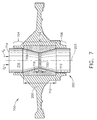
- Figure 7 is a side elevation view of another alternative stress relief tooling configuration 700 that may be used with disk 200 of high pressure turbine 22 (shown in Figure 1).
- Configuration 700 includes high pressure turbine disk 200 having a center bore 202 and longitudinal axis 203 therethrough.
- Bore 202 includes a first diameter portion 702 having a diameter larger than a second and third diameter portions 704 and 706.
- a segmented ring 708 may be fabricated of a plurality of circumferential segments of a length 710 that is substantially equal to the distance between second and third diameter portions 704 and 706.
- first diameter portion 702 forms a radially outward recess in a sidewall 712 of bore 202 and segmented ring 708 is sized to fit between second and third diameter portions 704 and 706.
- an axial force Fa applied to an engagement surface 714 of plug tool 716 generates a radial force Fr about a circumference of first diameter portion 702 and generating a hoop stress in high pressure turbine disk 200 through segmented ring 708.
- a width 718 of a gap 720 regulates an amount of radial force Fr applied to high pressure turbine disk 200 by limiting the travel of plug tool 716.
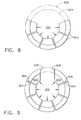
- Figure 8 is a plan view of a portion of exemplary segmented ring 708 installed within bore 202.
- Figure 9 is a plan view of another portion of segmented ring 708 installed within bore 202.
- Figure 10 is a plan view of a final portion of segmented ring 708 installed within bore 202.
- Segmented ring 708 includes a plurality of segments 802 that may be inserted axially into bore 202 to clear second and third diameter portions 704 and 706, and then may be slid radially outward until seated first diameter portion 702.
- Area 804 is defined by the diameter of second and third diameter portions 704 and 706, and area 806 is defined by the diameter of first diameter portion 702.
- a second portion of segments 902 may be inserted into bore 202 and slid radially outwardly into the recess formed by first diameter portion 702.
- Segments 902 are configured on a first side 904 to mate with a side 906 of adjacent segments 802.
- a second side 908 of segments 902 are substantially parallel with respect to each other. As illustrated in Figure 10, forming sides 908 parallel to each other permits installation of a last segment 910 into the recess formed by first diameter portion 702 between sides 908.
- Figure 11 is a flowchart illustrating an exemplary method 1100 of relieving residual stress in a workpiece, such as high pressure turbine disk 200.
- Disk 200 may be formed in a powder metal alloy forging process into a blank or forging heat treat shape, such that metal, in excess of the final machined size of the disk, may be permitted in the forging.
- the excess stock allows for forging process variations, manufacturing handling and tolerances, and other treating processes that may be used that remove metal from the forging to accomplish the process.
- the cooling portion of the forging process generates residual stresses into the workpiece, which, if not removed, may cause warping and/or growth of the final machined piece during operation. Such warpage an/or growth may affect clearance tolerances and part fit-up.
- the residual stress may be reduced by applying 1102 a predetermined axial force to a plug tool that is mated to an inner surface of a bore through the workpiece.
- the plug tool is of a frusto-conical profile and engages a bore in the workpiece with a convergent profile.
- the combination of the frusto-conical plug tool and convergent bore tends to resist the plug tool from advancing into the bore. This reaction translates 1104 the axial force into a radial force in the workpiece.
- the radial force acting radially outward from the bore into the workpiece generates 1106 a hoop stress that is predetermined to be of sufficient magnitude to at least partially reduce the residual stresses.
- the convergent profile of the bore may be formed in the forging process to provide a mating surface for the plug tool.
- the angle of convergence is approximately fifteen degrees with respect to the longitudinal axis of the workpiece. In other embodiments, the angle of convergence may be other predetermined angles.
- the workpiece bore may not be convergent but, rather may be a cylindrical or a compound cylindrical shape wherein several cylindrical profiles of different radii define the inner surface of the bore. In such cases, a ring may be used as a mating adapter between the plug tool and the bore.
- the outer periphery of the ring may be formed to match the inner surface of the bore, and the inner surface of the ring may be formed to match the profile and dimensions of the plug tool.
- the ring may be solid, slotted and/or segmented to facilitate expansion.
- the plug tool may comprise a double frusto-conical profile such that the narrow diameter of each frusto-conically shaped plug tool is adjacent the narrow diameter of the other plug tool. Accordingly, a ring used with a double frusto-conical plug tool may be formed to mate with two frusto-conical surfaces.
- the magnitude of radial force applied to the workpiece may be controlled by the distance the plug tool is permitted to travel in the bore.
- travel is limited by a gap defined between adjacent faces of the plug tool and the work surface or a gap defined between adjacent faces of the double frusto-conical plug tool.
- the plug bears on an immovable surface and ceases moving.
- the axial force is applied to the plug tool using a hydraulic ram and movement of the ram may be stopped using a control system monitoring the force applied directly, through for example a strain gauge or may monitor the gap distance and stop movement of the ram when the gap is closed.
- the above-described methods and apparatus for fabricating rotatable machines is cost-effective and highly reliable means for relieving residual stress in forged components without pre-spinning the component.
- Each embodiment may be performed with standard tooling available in forging and machining shops, and therefore is able to be completed in the normal course of fabrication. Accordingly, the stress relief methods described herein facilitate fabrication of forged components, while reducing cost and part cycle time, in a cost-effective and reliable manner.
- rotatable machine fabrication apparatus components Exemplary embodiments of rotatable machine fabrication apparatus components are described above in detail. The components are not limited to the specific embodiments described herein, but rather, components of each apparatus may be utilized independently and separately from other components described herein. Each rotatable machine fabrication apparatus component can also be used in combination with other rotatable machine fabrication apparatus components.
Abstract
Description
- This invention relates generally to gas turbine engines and, more particularly, to assembling rotating components of gas turbine engines.
- At least some known gas turbine engines include a core engine having, in serial flow arrangement, a fan assembly and a high pressure compressor which compresses airflow entering the engine. A combustor ignites a fuel-air mixture which is then channeled through a turbine nozzle assembly towards low and high pressure turbines which each include a disk having a plurality of rotor blades that extract rotational energy from gas flow exiting the combustor. Gas turbine engines are used in different operating environments, such as, to provide propulsion for aircraft and/or to produce power in both land-based and sea-borne power systems.
- During normal operations gas turbine engines may operate with high rotational speeds and relatively high temperatures. Residual stresses from a metal alloy forging process used in fabricating the turbine disks may relieve during engine operation, such that the turbine disks may undesirably expand. Moreover, such disk expansion may adversely affect rotor-to-casing clearances during operation.
- To facilitate reducing occurrences of disk expansion, at least some known engine disks are spun during the manufacturing process in a near-finished condition to relieve the residual stresses. Pre-spinning of the disks has generally the same effect on relieving the residual stress as actual engine operation. Final machining, such as, of mating features and/or rabbets, for example, is accomplished after the pre-spinning process. However, the pre-spinning process may be undesirable for several reasons, such as, for example, the costs, timing and logistics associated with removing the disk from the manufacturing cycle to perform the pre-spin process. Moreover, because the high rotational speeds are needed to relieve the residual stress, a balance condition of the disk and personnel safety issues may increase the complexity of the pre-spin process.
- In one aspect of the present invention, a method and apparatus for fabricating a workpiece is provided. The method includes applying a predetermined axial force to a tool; translating the axial force into a radial force in the workpiece using the tool, and generating a hoop stress in the work piece sufficient to relieve residual stress in the workpiece.
- In another aspect of the invention, a method of fabricating a gas turbine engine rotor disk is provided. The method includes forming a workpiece using a metal alloy forging process, reducing residual stress from the forging process using a tool to translate an axial force applied to the tool to a radial force in the workpiece, and final machining the workpiece.
- In yet another aspect, a rotor disk for a gas turbine engine is provided. The rotor disk includes a hub portion, and a center bore extending through the hub portion wherein the hub portion has residual stresses from a forging fabrication process at least partially relieved using a hoop stress induced into the hub portion from the center bore.
- Embodiments of the invention will now be described, by way of example, with reference to the accompanying drawings, in which:
- Figure 1 is a schematic illustration of an exemplary gas turbine engine;
- Figure 2 is a side elevation view of an exemplary stress relief tooling configuration that may be used with a disk of the high pressure turbine shown in Figure 1;
- Figure 3 is a side elevation view of an alternative stress relief tooling configuration that may be used with the disk of the high pressure turbine shown in Figure 1;
- Figure 4 is a plan view of an exemplary slotted ring that may be used with the plug tool shown in Figure 2;
- Figure 5 is a elevation view of an exemplary slotted ring that may be used with the double tapered plugs shown in Figure 3;
- Figure 6 is a side elevation view of another alternative stress relief tooling configuration that may be used with the disk of the high pressure turbine shown in Figure 1;
- Figure 7 is a side elevation view of another alternative stress relief tooling configuration that may be used with the disk of the high pressure turbine shown in Figure 1;
- Figure 8 is a plan view of a portion of an exemplary segmented ring installed within the disk bore;
- Figure 9 is a plan view of another portion of the segmented ring installed within the disk bore;
- Figure 10 is a plan view of a final portion of the segmented ring installed within the disk bore; and
- Figure 11 is a flowchart illustrating an exemplary method of relieving residual stress in a workpiece.
- Figure. 1 is a schematic illustration of an exemplary high bypass, turbofan
gas turbine engine 10 having in serial flow communication aninlet 12 for receivingambient air 14, afan 16, acompressor 18, acombustor 20, ahigh pressure turbine 22, and alow pressure turbine 24. Thehigh pressure turbine 22 is joined to thecompressor 18 by ahigh pressure shaft 26, and thelow pressure turbine 24 is connected to thefan 16 by a low pressure shaft, ordrive shaft 28.Engine 10 has an axis ofsymmetry 32 extending from anupstream side 34 ofengine 10 aft to adownstream side 36 ofengine 10. In one embodiment,gas turbine engine 10 is a GE90 engine commercially available from General Electric Company, Cincinnati, Ohio. - In operation, air flows through
fan 16 and compressed air is supplied tohighpressure compressor 18. Highly compressed air is delivered tocombustor 20.Combustion gases 38 fromcombustor 20propel turbines High pressure turbine 22 rotatessecond shaft 26 andhigh pressure compressor 18, whilelow pressure turbine 24 rotatesfirst shaft 28 andfan 16 aboutaxis 32. - Figure 2 is a side elevation view of an exemplary stress relief tooling configuration that may be used with a
disk 200 of high pressure turbine 22 (shown in Figure 1). In Figure 2, highpressure turbine disk 200 is illustrated in a forging heat treat shape, prior to final machining. Highpressure turbine disk 200 includes ahub portion 201 having acenter bore 202 therethrough and alongitudinal axis 203 about whichdisk 200 rotates during operation. Aweb portion 204 extends radially outward fromhub portion 201 and arim portion 205 extends radially outward fromweb portion 204.Center bore 202 includes an innercircumferential surface 206, at least a portion of which includesexcess stock 208 that may be removed during a subsequent machining process. An amount and location ofexcess stock 208 may define a radially convergent cross section throughbore 202. In the exemplary embodiment, an angle ofconvergence 210 is approximately fifteen degrees. In other embodiments, angle of convergence may be of other angular magnitudes. Aplug tool 212 includes a lowercylindrical portion 214, an uppercylindrical portion 216, and a frusto-conical portion 218 extending therebetween. Frusto-conical portion 218 includes anouter surface 220 with a frusto-conical cross-section that substantially mates to disk innercircumferential surface 206. In the exemplary embodiment,plug tool 212 is unitary. In an alternative embodiment,plug tool 212 is formed of a plurality of wedge sections extending circumferentially about innercircumferential surface 206. In another alternative embodiment,plug tool 212 is fabricated from a plurality of stackable tooling disks, each with an outside diameter that mates to innercircumferential surface 206. Uppercylindrical portion 216 includes anengagement face 226 that is substantially perpendicular tolongitudinal axis 203 and lowercylindrical portion 214 includes antravel stop face 228 that is substantially parallel toengagement face 226. Although the stress relief tooling configuration is described in relation to a high pressure turbine disk of a gas turbine engine, it should be understood the process may be used on any similarly configured workpiece and is not limited to the specific embodiment described herein. - During fabrication, high
pressure turbine disk 200 may be formed in a powder metal alloy forging process wherein highpressure turbine disk 200 is not machined to final tolerances, but rather is forged to blank dimensions. Final dimensions may be machined in subsequent processes wherein mating surfaces, attachments points, and slots are formed. During the forging process residual stresses remain in highpressure turbine disk 200. To relieve such stresses, a hoop stress is induced into highpressure turbine disk 200 throughbore 202 of a predetermined magnitude, which is sufficient to relieve the residual stresses. In the exemplary embodiment, an axial force Fa is applied toengagement face 226 through ahydraulic ram 230 in a direction 231 that is parallel tolongitudinal axis 203. Force Fa causesouter surface 220 to slidily engage innercircumferential surface 206 and move the larger diameter portion ofplug tool 212 intobore 202.Plug tool 212 bearing on innercircumferential surface 206 generates a radially outward force Fr about the circumference of innercircumferential surface 206. An axial travel ofplug tool 212 is limited to adistance 232 betweentravel stop face 228 and a workingsurface 234. Afterplug tool 212 has traveled throughdistance 232, contact betweentravel stop face 228 and workingsurface 234 substantially prevents further travel ofplug tool 212. Limiting travel ofplug tool 212 limits force Fr applied to highpressure turbine disk 200 to an amount predetermined to relieve the residual stresses from the forging process. Although fabrication of highpressure turbine disk 200 is described relative to a powder metal alloy forging process, it should be understood that the powder metal alloy forging process is illustrative of an exemplary fabrication process that may be used to form highpressure turbine disk 200 and is not limiting to only this process. - Figure 3 is a side elevation view of an alternative stress
relief tooling configuration 300 that may be used withdisk 200 of high pressure turbine 22 (shown in Figure 1). In Figure 3, highpressure turbine disk 200 is illustrated in a forging heat treat shape, prior to final machining. Highpressure turbine disk 200 includes a center bore 202 andlongitudinal axis 203 therethrough. Center bore 202 includes an innercircumferential surface 206, at least a portion of which includesexcess stock 208 that may be removed during a subsequent machining process. An amount and location ofexcess stock 208 may define a cylindrical cross section throughbore 202. - A
plug tool 302 used inconfiguration 300 includes a first frusto-conical member 304 and a second frusto-conical member 306. Each frusto-conical member large diameter end smaller diameter end 312 and 314, respectively. Each frusto-conical member taper sidewall convergence 210 of eachsidewall angle 210 is another angular magnitude. In yet another embodiment, angle ofconvergence 210 ofsidewall 316 is not equal to angle ofconvergence 210 ofsidewall 318. -
Configuration 300 includes a doubletaper mating ring 320 having an outercylindrical surface 322 sized to mate with innercircumferential surface 206 ofdisk 200 and a radially inner doubletapered surface 324 configured to mate to sidewalls 316 and 318. When fully assembled, agap 326 is defined between atravel stop face 328 ofsmaller diameter end 312 and atravel stop face 330 of smaller diameter end 314. A width 332 ofgap 326 defines a distance of travel of frusto-conical member 306 during a stress relief process described below in greater detail. - During fabrication, frusto-
conical members longitudinal axis 203 inbore 202, such that frusto-conical members taper mating ring 320 and highpressure turbine disk 200. An axial force Fa may be applied to anupper surface 334 of frusto-conical member 306. Force Fa drives frusto-conical member 306 alonglongitudinal axis 203 untiltravel stop face 330 mates withtravel stop face 328. The axial movement of frusto-conical member 306 transmits a second axial force to doubletaper mating ring 320 causing it to slide alongsidewall 316. The resulting compression due to the taper sidewalls and frusto-conical shape ofmembers circumferential surface 206 ofdisk 200, such that hoop stresses are generated indisk 200 that are of sufficient magnitude to relieve the residual stresses indisk 200 from the forging process. - Figure 4 is a plan view of an exemplary slotted
ring 400 that may be used with plug tool 212 (shown in Figure 2). Figure 5 is a elevation view of a slotted ring 500 that may be used with the doubletapered plugs 304 and 306 (shown in Figure 3). Slotted rings 400 and 500 may include a plurality of lengthwisepartial slots plug 212 and/or doubletapered plugs Slots 402 and/ or 502 may be formed through at least a portion of an axial length ofplug 212 and through at least a portion of anaxial length 504 of doubletapered plugs plug 212 and/or doubletapered plugs - Figure 6 is a side elevation view of another alternative stress
relief tooling configuration 600 that may be used withdisk 200 of high pressure turbine 22 (shown in Figure 1). In Figure 6, highpressure turbine disk 200 is illustrated in a forging heat treat shape, prior to final machining. Highpressure turbine disk 200 includes center bore 202 andlongitudinal axis 203 therethrough. Center bore 202 includes an innercircumferential surface 206, at least a portion of which includesexcess stock 208 that may be removed during a subsequent machining process. An amount and location ofexcess stock 208 may define a cylindrical cross section throughbore 202. In the exemplary embodiment, innercircumferential surface 206 also includes at least one of radial discontinuity, such as alip 602 that may preclude use of a single taper or double taper plug tool.Configuration 600 includes a slottedring 604 having an outer surface 606 machined to mate to innercircumferential surface 206 includinglip 602 and any other radial discontinuities or radial shapes that may be formed in innercircumferential surface 206. Slottedring 604 may also be segmented, such that a plurality of circumferential segments are spaced circumferentially along innercircumferential surface 206. A plug tool 606 used inconfiguration 600 is substantially similar to plugtool 302 used in configuration 300 (shown in Figure 3). - Figure 7 is a side elevation view of another alternative stress
relief tooling configuration 700 that may be used withdisk 200 of high pressure turbine 22 (shown in Figure 1).Configuration 700 includes highpressure turbine disk 200 having a center bore 202 andlongitudinal axis 203 therethrough.Bore 202 includes afirst diameter portion 702 having a diameter larger than a second andthird diameter portions segmented ring 708 may be fabricated of a plurality of circumferential segments of alength 710 that is substantially equal to the distance between second andthird diameter portions first diameter portion 702 forms a radially outward recess in asidewall 712 ofbore 202 and segmentedring 708 is sized to fit between second andthird diameter portions engagement surface 714 ofplug tool 716 generates a radial force Fr about a circumference offirst diameter portion 702 and generating a hoop stress in highpressure turbine disk 200 through segmentedring 708. Awidth 718 of agap 720 regulates an amount of radial force Fr applied to highpressure turbine disk 200 by limiting the travel ofplug tool 716. - Figure 8 is a plan view of a portion of exemplary
segmented ring 708 installed withinbore 202. Figure 9 is a plan view of another portion of segmentedring 708 installed withinbore 202. Figure 10 is a plan view of a final portion of segmentedring 708 installed withinbore 202.Segmented ring 708 includes a plurality ofsegments 802 that may be inserted axially intobore 202 to clear second andthird diameter portions first diameter portion 702.Area 804 is defined by the diameter of second andthird diameter portions area 806 is defined by the diameter offirst diameter portion 702. As illustrated in Figure 9, a second portion ofsegments 902 may be inserted intobore 202 and slid radially outwardly into the recess formed byfirst diameter portion 702.Segments 902 are configured on afirst side 904 to mate with aside 906 ofadjacent segments 802. Asecond side 908 ofsegments 902 are substantially parallel with respect to each other. As illustrated in Figure 10, formingsides 908 parallel to each other permits installation of alast segment 910 into the recess formed byfirst diameter portion 702 betweensides 908. - Figure 11 is a flowchart illustrating an
exemplary method 1100 of relieving residual stress in a workpiece, such as highpressure turbine disk 200.Disk 200 may be formed in a powder metal alloy forging process into a blank or forging heat treat shape, such that metal, in excess of the final machined size of the disk, may be permitted in the forging. The excess stock allows for forging process variations, manufacturing handling and tolerances, and other treating processes that may be used that remove metal from the forging to accomplish the process. The cooling portion of the forging process generates residual stresses into the workpiece, which, if not removed, may cause warping and/or growth of the final machined piece during operation. Such warpage an/or growth may affect clearance tolerances and part fit-up. The residual stress may be reduced by applying 1102 a predetermined axial force to a plug tool that is mated to an inner surface of a bore through the workpiece. In the exemplary embodiment, the plug tool is of a frusto-conical profile and engages a bore in the workpiece with a convergent profile. As an axial force is applied to the plug tool, forcing it into the bore, the combination of the frusto-conical plug tool and convergent bore tends to resist the plug tool from advancing into the bore. This reaction translates 1104 the axial force into a radial force in the workpiece. The radial force acting radially outward from the bore into the workpiece generates 1106 a hoop stress that is predetermined to be of sufficient magnitude to at least partially reduce the residual stresses. The convergent profile of the bore may be formed in the forging process to provide a mating surface for the plug tool. In the exemplary embodiment, the angle of convergence is approximately fifteen degrees with respect to the longitudinal axis of the workpiece. In other embodiments, the angle of convergence may be other predetermined angles. Additionally, the workpiece bore may not be convergent but, rather may be a cylindrical or a compound cylindrical shape wherein several cylindrical profiles of different radii define the inner surface of the bore. In such cases, a ring may be used as a mating adapter between the plug tool and the bore. For example, the outer periphery of the ring may be formed to match the inner surface of the bore, and the inner surface of the ring may be formed to match the profile and dimensions of the plug tool. The ring may be solid, slotted and/or segmented to facilitate expansion. The plug tool may comprise a double frusto-conical profile such that the narrow diameter of each frusto-conically shaped plug tool is adjacent the narrow diameter of the other plug tool. Accordingly, a ring used with a double frusto-conical plug tool may be formed to mate with two frusto-conical surfaces. - The magnitude of radial force applied to the workpiece may be controlled by the distance the plug tool is permitted to travel in the bore. In the exemplary embodiment, travel is limited by a gap defined between adjacent faces of the plug tool and the work surface or a gap defined between adjacent faces of the double frusto-conical plug tool. When the gap is closed, the plug bears on an immovable surface and ceases moving. In the exemplary embodiment, the axial force is applied to the plug tool using a hydraulic ram and movement of the ram may be stopped using a control system monitoring the force applied directly, through for example a strain gauge or may monitor the gap distance and stop movement of the ram when the gap is closed.
- The above-described methods and apparatus for fabricating rotatable machines is cost-effective and highly reliable means for relieving residual stress in forged components without pre-spinning the component. Each embodiment may be performed with standard tooling available in forging and machining shops, and therefore is able to be completed in the normal course of fabrication. Accordingly, the stress relief methods described herein facilitate fabrication of forged components, while reducing cost and part cycle time, in a cost-effective and reliable manner.
- Exemplary embodiments of rotatable machine fabrication apparatus components are described above in detail. The components are not limited to the specific embodiments described herein, but rather, components of each apparatus may be utilized independently and separately from other components described herein. Each rotatable machine fabrication apparatus component can also be used in combination with other rotatable machine fabrication apparatus components.
Claims (10)
- A method (1100) of fabricating a workpiece (200), said method comprising:applying (1102) a predetermined axial force to a tool (212); translating (1104) the axial force into a radial force in the workpiece using the tool; andgenerating (1106) a hoop stress in the work piece sufficient to relieve residual stress in the workpiece.
- A method in accordance with Claim 1 wherein the workpiece includes a bore (202) extending therethrough, said method further comprising:positioning a ring (320) radially outward from the tool to mate with the workpiece wherein the ring includes at least one of longitudinally-oriented slots (402) and longitudinally-oriented segments (802); andtranslating the axial force into a radial force through the ring to the workpiece.
- A method in accordance with Claim 1 wherein the workpiece includes a bore extending therethrough wherein at least a portion of the bore is radially convergent, and wherein translating the axial force into a radial force in the workpiece comprises pressing a frusto-conical portion (218) of the tool into the bore.
- A method in accordance with Claim 1 wherein the workpiece includes a substantially cylindrical bore extending therethrough, said method further comprises:positioning a ring (320) radially outward from the tool such that a radially outer surface of the ring is configured to mate with the workpiece;inserting a double frusto-conical cross-sectional portion (324) of the tool within the bore; andtranslating the axial force into a radial force through the ring to the workpiece.
- A method in accordance with Claim 1 wherein the workpiece includes a bore extending therethrough and having a plurality of substantially cylindrical axially-spaced surfaces, said method further comprising:positioning a ring radially outward from the tool such that a radially outer surface of the ring is configured to mate with the workpieceinserting a double frusto-conical cross-sectional portion of the tool within the bore; andtranslating the axial force into a radial force through the ring to the workpiece.
- A method in accordance with Claim 5 wherein a surface defining the bore includes a recessed circumferential portion, and wherein positioning a ring radially outward from the tool comprises:providing a segmented ring (708) having a plurality of longitudinal segments (802);inserting each longitudinal segment into the bore; andtranslating each segment radially outward such that an outer peripheral surface of each segment mates with a corresponding radially inner surface of the recessed circumferential portion.
- A method in accordance with Claim 1 further comprising fabricating the workpiece using a metal alloy forging process.
- A method in accordance with Claim 1 further comprising fabricating the workpiece to a forging heat treat shape that includes a predetermined portion of excess stock remaining on the workpiece when relieving residual stress in the workpiece.
- A method in accordance with Claim 1 wherein applying a predetermined axial force to a tool comprises applying a predetermined axial force to the tool using a hydraulic ram.
- A method in accordance with Claim 1 wherein an axial gap (326) adjacent a travel stop face (328, 330) of the tool defines a limit of travel of the tool, and wherein applying a predetermined axial force to a tool comprises:determining a desired axial gap distance that is adjacent to the travel stop face wherein the axial gap distance corresponds to the predetermined axial force;providing an axial gap that is adjacent to the travel stop face that is approximately equal to the desired axial gap distance, andaxially pressing the tool until the gap is substantially closed.
Applications Claiming Priority (1)
| Application Number | Priority Date | Filing Date | Title |
|---|---|---|---|
| US10/882,367 US7464577B2 (en) | 2004-07-01 | 2004-07-01 | Method for fabricating rotary machines |
Publications (2)
| Publication Number | Publication Date |
|---|---|
| EP1611976A1 true EP1611976A1 (en) | 2006-01-04 |
| EP1611976B1 EP1611976B1 (en) | 2017-05-31 |
Family
ID=35033524
Family Applications (1)
| Application Number | Title | Priority Date | Filing Date |
|---|---|---|---|
| EP05254011.9A Expired - Fee Related EP1611976B1 (en) | 2004-07-01 | 2005-06-28 | Methods and apparatus for fabricating rotatable machines |
Country Status (3)
| Country | Link |
|---|---|
| US (1) | US7464577B2 (en) |
| EP (1) | EP1611976B1 (en) |
| JP (1) | JP5475209B2 (en) |
Cited By (23)
| Publication number | Priority date | Publication date | Assignee | Title |
|---|---|---|---|---|
| EP1801349A1 (en) * | 2005-12-20 | 2007-06-27 | General Electric Company | High pressure turbine disk hub with reduced axial stress and method |
| WO2007121932A1 (en) * | 2006-04-24 | 2007-11-01 | Airbus France | Expansion tool for cold expansion of holes |
| US7926318B2 (en) | 2006-04-27 | 2011-04-19 | Fatigue Technology, Inc. | Alignment device and methods of using the same |
| US7926319B2 (en) | 2005-12-28 | 2011-04-19 | Fatigue Technology, Inc. | Mandrel assembly and method of using the same |
| US7946628B2 (en) | 2003-07-31 | 2011-05-24 | Fatigue Technology, Inc. | Tubular metal fitting expandable in a wall opening and method of installation |
| US7958766B2 (en) | 2006-06-29 | 2011-06-14 | Fatigue Technology, Inc. | Self-aligning tools and a mandrel with retention sleeve |
| WO2010098939A3 (en) * | 2009-02-25 | 2011-06-30 | General Electric Company | Method and apparatus for pre-spinning rotor forgings |
| FR2956601A1 (en) * | 2010-02-22 | 2011-08-26 | Snecma | Method for reinforcing mechanical characteristics of wall delimiting bore of disk of turbojet engine by plasticization, involves retracting rod from outlet position toward inserted position in actuator such that tool traverses disk bore |
| US8069699B2 (en) | 2006-08-28 | 2011-12-06 | Fatigue Technology, Inc. | Installation/processing systems and methods of using the same |
| US8128308B2 (en) | 2000-06-26 | 2012-03-06 | Fatigue Technology Inc. | Double flanged bushings and installation methods |
| US8312606B2 (en) | 2007-10-16 | 2012-11-20 | Fatigue Technology, Inc. | Expandable fastener assembly with deformed collar |
| US8506222B2 (en) | 2008-07-18 | 2013-08-13 | Fatigue Technology, Inc. | Nut plate assembly and methods of using the same |
| US8568034B2 (en) | 2006-01-11 | 2013-10-29 | Fatigue Technology, Inc. | Bushing kits, bearings, and methods of installation |
| DE102012010793A1 (en) | 2012-06-01 | 2013-12-05 | Eads Deutschland Gmbh | Forming tool for expanding an opening with a Aufweitvorrrichtung |
| US8636455B2 (en) | 2009-04-10 | 2014-01-28 | Fatigue Technoloy, Inc. | Installable assembly having an expandable outer member and a fastener with a mandrel |
| CN103551813A (en) * | 2013-11-11 | 2014-02-05 | 中国南方航空工业(集团)有限公司 | Machining method for plasma-sprayed surface of internal annular surface of annular housing |
| US8647035B2 (en) | 2009-12-16 | 2014-02-11 | Fatigue Technology, Inc. | Modular nut plate assemblies and methods of using the same |
| US8763229B2 (en) | 2011-06-03 | 2014-07-01 | Fatigue Technology, Inc. | Expandable crack inhibitor method |
| US8938886B2 (en) | 2012-01-30 | 2015-01-27 | Fatigue Technology, Inc. | Smart installation/processing systems, components, and methods of operating the same |
| US9114449B2 (en) | 2011-06-15 | 2015-08-25 | Fatigue Technology, Inc. | Modular nut plates with closed nut assemblies |
| US10010983B2 (en) | 2008-03-07 | 2018-07-03 | Fatigue Technology, Inc. | Expandable member with wave inhibitor and methods of using the same |
| EP3756786A1 (en) * | 2019-06-24 | 2020-12-30 | Garrett Transportation I Inc. | Treatment process for a central bore through a centrifugal compressor wheel to create a zone of compressive residual hoop stress on a fractional portion of the bore length, and compressor wheel resulting therefrom |
| FR3100147A1 (en) * | 2019-09-04 | 2021-03-05 | Safran Aircraft Engines | PROCESS FOR RELAXATION OF THE CONSTRAINTS BY ROTATION |
Families Citing this family (5)
| Publication number | Priority date | Publication date | Assignee | Title |
|---|---|---|---|---|
| JP2009079495A (en) * | 2007-09-25 | 2009-04-16 | Toshiba Corp | Deformation-correction method for gas-turbine component |
| US20200406338A1 (en) * | 2018-02-13 | 2020-12-31 | Nsk Ltd. | Dynamic load measurement method for rotary forging device, dynamic load measuring device, method for calibrating rotary forging device, method for manufacturing hub unit bearing, and method for manufacturing vehicle |
| CN112100765B (en) * | 2020-08-28 | 2022-08-26 | 北京航空航天大学 | High-low cycle composite fatigue test piece of turbine disc cold extrusion reinforced hole structure and design method |
| US11648632B1 (en) | 2021-11-22 | 2023-05-16 | Garrett Transportation I Inc. | Treatment process for a centrifugal compressor wheel to extend low-cycle fatigue life |
| CN115431001B (en) * | 2022-10-08 | 2023-06-30 | 中国科学院光电技术研究所 | Precision machining method for high-precision gyro rotor parts |
Citations (5)
| Publication number | Priority date | Publication date | Assignee | Title |
|---|---|---|---|---|
| US1937878A (en) | 1931-06-22 | 1933-12-05 | Edgewater Steel | Method of making wheels |
| US4074560A (en) * | 1976-11-22 | 1978-02-21 | Sisk Hollis D | Apparatus and method for sizing stator bores |
| US4411715A (en) * | 1981-06-03 | 1983-10-25 | The United States Of America As Represented By The Secretary Of The Air Force | Method of enhancing rotor bore cyclic life |
| US6241832B1 (en) * | 2000-01-12 | 2001-06-05 | General Electric Company | Method for creep-sizing annular-shaped structures and device therefor |
| US20040179939A1 (en) * | 2003-03-12 | 2004-09-16 | Pcc Structurals, Inc. | Double-walled annular articles and apparatus and method for sizing the same |
Family Cites Families (24)
| Publication number | Priority date | Publication date | Assignee | Title |
|---|---|---|---|---|
| US2848805A (en) * | 1955-08-12 | 1958-08-26 | Firestone Tire & Rubber Co | Method of making a drop center one piece tubeless tire rim |
| US3009747A (en) * | 1956-11-23 | 1961-11-21 | Paul Gross | Bushing |
| US3381515A (en) | 1965-11-01 | 1968-05-07 | Huck Mfg Co | Cold forming die construction |
| US3433382A (en) * | 1967-05-22 | 1969-03-18 | Barogenics Inc | Pre-stressed segmented containers or pressure vessels |
| US3828422A (en) * | 1970-08-05 | 1974-08-13 | Boeing Co | Method of making fatigue resistant fastener joint |
| US4164807A (en) * | 1974-03-19 | 1979-08-21 | King John O Jun | Method of forming a coldworked joint |
| US3892121A (en) * | 1973-09-12 | 1975-07-01 | Boeing Co | Apparatus for cold-working holes |
| US3986383A (en) * | 1974-01-02 | 1976-10-19 | Petteys Howard A | Expander tool |
| US4008598A (en) * | 1975-11-13 | 1977-02-22 | Asko, Inc. | Work reducing |
| US4187708A (en) * | 1977-04-11 | 1980-02-12 | Industrial Wire & Metal Forming, Inc. | Pulling apparatus and method |
| JPS555823A (en) * | 1978-06-27 | 1980-01-17 | Kubota Ltd | Method for molding enlarged socket |
| JPS5634627U (en) * | 1979-08-23 | 1981-04-04 | ||
| US4370788A (en) * | 1979-09-07 | 1983-02-01 | Cross Manufacturing Company Limited | Method of lining cylindrical bores |
| US4557033A (en) * | 1983-07-11 | 1985-12-10 | Fatigue Technology, Inc. | Method of cold expanding and sizing fastener holes |
| JPS60118339A (en) | 1983-11-30 | 1985-06-25 | Toyoda Gosei Co Ltd | Metal forming device |
| JPH01138035A (en) * | 1987-11-20 | 1989-05-30 | Sumitomo Metal Ind Ltd | Pipe expansion method for seamless tube |
| US5213475A (en) | 1991-12-05 | 1993-05-25 | General Electric Company | Burst resistant rotor disk assembly |
| US5360240A (en) * | 1993-03-05 | 1994-11-01 | Hydril Company | Method of connecting plastic pipe joints to form a liner for an existing pipeline and a plastic pipe joint for forming such liner |
| JP3373619B2 (en) * | 1993-09-21 | 2003-02-04 | 三興精機株式会社 | Press molding method for annular molded products |
| JP3060926B2 (en) * | 1995-12-28 | 2000-07-10 | 住友金属工業株式会社 | Mechanical expansion method in UOE pipe manufacturing method |
| US5836197A (en) * | 1996-12-16 | 1998-11-17 | Mckee Machine Tool Corp. | Integral machine tool assemblies |
| JP3753220B2 (en) * | 1999-10-07 | 2006-03-08 | トヨタ自動車株式会社 | Forging apparatus and forging method |
| US6508145B1 (en) * | 1999-10-12 | 2003-01-21 | Toray Composites (America), Inc. | Press-fit multi-ring composite flywheel rim |
| JP2002059231A (en) * | 2000-08-10 | 2002-02-26 | Komatsu Ltd | Method of manufacturing pedestal mounting rotating ring and its pedestal |
-
2004
- 2004-07-01 US US10/882,367 patent/US7464577B2/en active Active
-
2005
- 2005-06-28 EP EP05254011.9A patent/EP1611976B1/en not_active Expired - Fee Related
- 2005-06-30 JP JP2005191536A patent/JP5475209B2/en not_active Expired - Fee Related
Patent Citations (5)
| Publication number | Priority date | Publication date | Assignee | Title |
|---|---|---|---|---|
| US1937878A (en) | 1931-06-22 | 1933-12-05 | Edgewater Steel | Method of making wheels |
| US4074560A (en) * | 1976-11-22 | 1978-02-21 | Sisk Hollis D | Apparatus and method for sizing stator bores |
| US4411715A (en) * | 1981-06-03 | 1983-10-25 | The United States Of America As Represented By The Secretary Of The Air Force | Method of enhancing rotor bore cyclic life |
| US6241832B1 (en) * | 2000-01-12 | 2001-06-05 | General Electric Company | Method for creep-sizing annular-shaped structures and device therefor |
| US20040179939A1 (en) * | 2003-03-12 | 2004-09-16 | Pcc Structurals, Inc. | Double-walled annular articles and apparatus and method for sizing the same |
Cited By (39)
| Publication number | Priority date | Publication date | Assignee | Title |
|---|---|---|---|---|
| US8128308B2 (en) | 2000-06-26 | 2012-03-06 | Fatigue Technology Inc. | Double flanged bushings and installation methods |
| US7946628B2 (en) | 2003-07-31 | 2011-05-24 | Fatigue Technology, Inc. | Tubular metal fitting expandable in a wall opening and method of installation |
| EP1801349A1 (en) * | 2005-12-20 | 2007-06-27 | General Electric Company | High pressure turbine disk hub with reduced axial stress and method |
| US7926319B2 (en) | 2005-12-28 | 2011-04-19 | Fatigue Technology, Inc. | Mandrel assembly and method of using the same |
| US8353193B2 (en) | 2005-12-28 | 2013-01-15 | Fatigue Technology, Inc. | Mandrel assembly and method of using the same |
| US8568034B2 (en) | 2006-01-11 | 2013-10-29 | Fatigue Technology, Inc. | Bushing kits, bearings, and methods of installation |
| EP2457687A1 (en) * | 2006-04-24 | 2012-05-30 | Airbus Operations | Expansion tool and method for cold expansion of holes |
| CN101437649B (en) * | 2006-04-24 | 2013-06-12 | 空中客车法国公司 | Expansion tool for cold expansion of holes |
| US8302448B2 (en) | 2006-04-24 | 2012-11-06 | Airbus Operations Sas | Expansion tool and method for cold expansion of holes |
| WO2007121932A1 (en) * | 2006-04-24 | 2007-11-01 | Airbus France | Expansion tool for cold expansion of holes |
| US8387436B2 (en) | 2006-04-27 | 2013-03-05 | Fatigue Technology, Inc. | Alignment device and methods of using the same |
| US7926318B2 (en) | 2006-04-27 | 2011-04-19 | Fatigue Technology, Inc. | Alignment device and methods of using the same |
| US8191395B2 (en) | 2006-04-27 | 2012-06-05 | Fatigue Technology, Inc. | Alignment device and methods of using the same |
| US8061178B2 (en) | 2006-06-29 | 2011-11-22 | Fatigue Technology, Inc. | Self-aligning tools and seating assemblies |
| US8117885B2 (en) | 2006-06-29 | 2012-02-21 | Fatigue Technology, Inc. | Mandrel with retention sleeve and methods of using the same |
| US7958766B2 (en) | 2006-06-29 | 2011-06-14 | Fatigue Technology, Inc. | Self-aligning tools and a mandrel with retention sleeve |
| US8069699B2 (en) | 2006-08-28 | 2011-12-06 | Fatigue Technology, Inc. | Installation/processing systems and methods of using the same |
| US8402806B2 (en) | 2006-08-28 | 2013-03-26 | Fatigue Technology, Inc. | Installation/processing systems and methods of using the same |
| US8312606B2 (en) | 2007-10-16 | 2012-11-20 | Fatigue Technology, Inc. | Expandable fastener assembly with deformed collar |
| US10010983B2 (en) | 2008-03-07 | 2018-07-03 | Fatigue Technology, Inc. | Expandable member with wave inhibitor and methods of using the same |
| US8506222B2 (en) | 2008-07-18 | 2013-08-13 | Fatigue Technology, Inc. | Nut plate assembly and methods of using the same |
| US8051709B2 (en) | 2009-02-25 | 2011-11-08 | General Electric Company | Method and apparatus for pre-spinning rotor forgings |
| WO2010098939A3 (en) * | 2009-02-25 | 2011-06-30 | General Electric Company | Method and apparatus for pre-spinning rotor forgings |
| US8636455B2 (en) | 2009-04-10 | 2014-01-28 | Fatigue Technoloy, Inc. | Installable assembly having an expandable outer member and a fastener with a mandrel |
| US8647035B2 (en) | 2009-12-16 | 2014-02-11 | Fatigue Technology, Inc. | Modular nut plate assemblies and methods of using the same |
| FR2956601A1 (en) * | 2010-02-22 | 2011-08-26 | Snecma | Method for reinforcing mechanical characteristics of wall delimiting bore of disk of turbojet engine by plasticization, involves retracting rod from outlet position toward inserted position in actuator such that tool traverses disk bore |
| US8763229B2 (en) | 2011-06-03 | 2014-07-01 | Fatigue Technology, Inc. | Expandable crack inhibitor method |
| US9114449B2 (en) | 2011-06-15 | 2015-08-25 | Fatigue Technology, Inc. | Modular nut plates with closed nut assemblies |
| US10130985B2 (en) | 2012-01-30 | 2018-11-20 | Fatigue Technology, Inc. | Smart installation/processing systems, components, and methods of operating the same |
| US8938886B2 (en) | 2012-01-30 | 2015-01-27 | Fatigue Technology, Inc. | Smart installation/processing systems, components, and methods of operating the same |
| US10843250B2 (en) | 2012-01-30 | 2020-11-24 | Fatigue Technology, Inc. | Smart installation/processing systems, components, and methods of operating the same |
| WO2013178211A1 (en) | 2012-06-01 | 2013-12-05 | Eads Deutschland Gmbh | Forming tool and method for enlarging an opening by means of an enlarging device |
| DE102012010793A1 (en) | 2012-06-01 | 2013-12-05 | Eads Deutschland Gmbh | Forming tool for expanding an opening with a Aufweitvorrrichtung |
| CN103551813A (en) * | 2013-11-11 | 2014-02-05 | 中国南方航空工业(集团)有限公司 | Machining method for plasma-sprayed surface of internal annular surface of annular housing |
| EP3756786A1 (en) * | 2019-06-24 | 2020-12-30 | Garrett Transportation I Inc. | Treatment process for a central bore through a centrifugal compressor wheel to create a zone of compressive residual hoop stress on a fractional portion of the bore length, and compressor wheel resulting therefrom |
| US11473588B2 (en) | 2019-06-24 | 2022-10-18 | Garrett Transportation I Inc. | Treatment process for a central bore through a centrifugal compressor wheel to create a deep cylindrical zone of compressive residual hoop stress on a fractional portion of the bore length, and compressor wheel resulting therefrom |
| FR3100147A1 (en) * | 2019-09-04 | 2021-03-05 | Safran Aircraft Engines | PROCESS FOR RELAXATION OF THE CONSTRAINTS BY ROTATION |
| WO2021044098A1 (en) * | 2019-09-04 | 2021-03-11 | Safran Aircraft Engines | Method for relieving stresses by rotation |
| US11913086B2 (en) | 2019-09-04 | 2024-02-27 | Safran Aircraft Engines | Method for relieving stresses by rotation |
Also Published As
| Publication number | Publication date |
|---|---|
| US20060000089A1 (en) | 2006-01-05 |
| US7464577B2 (en) | 2008-12-16 |
| JP2006017125A (en) | 2006-01-19 |
| JP5475209B2 (en) | 2014-04-16 |
| EP1611976B1 (en) | 2017-05-31 |
Similar Documents
| Publication | Publication Date | Title |
|---|---|---|
| EP1611976B1 (en) | Methods and apparatus for fabricating rotatable machines | |
| US9943932B2 (en) | Trunnion hole repair method utilizing interference fit inserts | |
| US10443615B2 (en) | Alignment of flanged components | |
| US8763248B2 (en) | Method for manufacturing aircraft engine cases with bosses | |
| EP1774141B1 (en) | Turbine case reinforcement in a gas turbine jet engine | |
| US20170002674A1 (en) | Turbine shroud with clamped flange attachment | |
| EP2113634B1 (en) | Method of repairing a gas turbine engine case with replaced flange using cold metal transfer | |
| US8510926B2 (en) | Method for repairing a gas turbine engine component | |
| EP2484867A2 (en) | Rotating component of a turbine engine | |
| CA2053036A1 (en) | Apparatus and method for supporting a vane segment in a gas turbine | |
| US20140377070A1 (en) | Axial Turbomachine Compressor Drum with Dual Means of Blade Fixing | |
| US20180281134A1 (en) | Method for Redistributing Residual Stress in an Engine Component | |
| US20050252000A1 (en) | Method and system for improved blade tip clearance in a gas turbine jet engine | |
| US20150354361A1 (en) | Rotor assembly and method of manufacturing thereof | |
| US20180283456A1 (en) | Turbine engine bearing assembly and method for assembling the same | |
| US20190195072A1 (en) | Turbine rotor disc having multiple rims | |
| US11773751B1 (en) | Ceramic matrix composite blade track segment with pin-locating threaded insert |
Legal Events
| Date | Code | Title | Description |
|---|---|---|---|
| PUAI | Public reference made under article 153(3) epc to a published international application that has entered the european phase |
Free format text: ORIGINAL CODE: 0009012 |
|
| AK | Designated contracting states |
Kind code of ref document: A1 Designated state(s): AT BE BG CH CY CZ DE DK EE ES FI FR GB GR HU IE IS IT LI LT LU MC NL PL PT RO SE SI SK TR |
|
| AX | Request for extension of the european patent |
Extension state: AL BA HR LV MK YU |
|
| 17P | Request for examination filed |
Effective date: 20060704 |
|
| AKX | Designation fees paid |
Designated state(s): DE FR GB IT |
|
| 17Q | First examination report despatched |
Effective date: 20061107 |
|
| GRAP | Despatch of communication of intention to grant a patent |
Free format text: ORIGINAL CODE: EPIDOSNIGR1 |
|
| INTG | Intention to grant announced |
Effective date: 20170201 |
|
| GRAS | Grant fee paid |
Free format text: ORIGINAL CODE: EPIDOSNIGR3 |
|
| GRAA | (expected) grant |
Free format text: ORIGINAL CODE: 0009210 |
|
| AK | Designated contracting states |
Kind code of ref document: B1 Designated state(s): DE FR GB IT |
|
| REG | Reference to a national code |
Ref country code: GB Ref legal event code: FG4D |
|
| REG | Reference to a national code |
Ref country code: FR Ref legal event code: PLFP Year of fee payment: 13 |
|
| REG | Reference to a national code |
Ref country code: DE Ref legal event code: R096 Ref document number: 602005052030 Country of ref document: DE |
|
| PGFP | Annual fee paid to national office [announced via postgrant information from national office to epo] |
Ref country code: FR Payment date: 20170627 Year of fee payment: 13 Ref country code: GB Payment date: 20170627 Year of fee payment: 13 |
|
| PGFP | Annual fee paid to national office [announced via postgrant information from national office to epo] |
Ref country code: DE Payment date: 20170628 Year of fee payment: 13 Ref country code: IT Payment date: 20170725 Year of fee payment: 13 |
|
| REG | Reference to a national code |
Ref country code: DE Ref legal event code: R097 Ref document number: 602005052030 Country of ref document: DE |
|
| PLBE | No opposition filed within time limit |
Free format text: ORIGINAL CODE: 0009261 |
|
| STAA | Information on the status of an ep patent application or granted ep patent |
Free format text: STATUS: NO OPPOSITION FILED WITHIN TIME LIMIT |
|
| 26N | No opposition filed |
Effective date: 20180301 |
|
| REG | Reference to a national code |
Ref country code: DE Ref legal event code: R119 Ref document number: 602005052030 Country of ref document: DE |
|
| GBPC | Gb: european patent ceased through non-payment of renewal fee |
Effective date: 20180628 |
|
| PG25 | Lapsed in a contracting state [announced via postgrant information from national office to epo] |
Ref country code: FR Free format text: LAPSE BECAUSE OF NON-PAYMENT OF DUE FEES Effective date: 20180630 Ref country code: GB Free format text: LAPSE BECAUSE OF NON-PAYMENT OF DUE FEES Effective date: 20180628 Ref country code: IT Free format text: LAPSE BECAUSE OF NON-PAYMENT OF DUE FEES Effective date: 20180628 Ref country code: DE Free format text: LAPSE BECAUSE OF NON-PAYMENT OF DUE FEES Effective date: 20190101 |