EP1611356B1 - Scroll compressor with bifurcated flow pattern - Google Patents
Scroll compressor with bifurcated flow pattern Download PDFInfo
- Publication number
- EP1611356B1 EP1611356B1 EP04709444A EP04709444A EP1611356B1 EP 1611356 B1 EP1611356 B1 EP 1611356B1 EP 04709444 A EP04709444 A EP 04709444A EP 04709444 A EP04709444 A EP 04709444A EP 1611356 B1 EP1611356 B1 EP 1611356B1
- Authority
- EP
- European Patent Office
- Prior art keywords
- gas
- compressor
- scroll
- scroll compressor
- passageway
- Prior art date
- Legal status (The legal status is an assumption and is not a legal conclusion. Google has not performed a legal analysis and makes no representation as to the accuracy of the status listed.)
- Expired - Lifetime
Links
- 239000000314 lubricant Substances 0.000 claims description 8
- 238000000034 method Methods 0.000 claims description 5
- 239000012530 fluid Substances 0.000 claims description 4
- 238000004891 communication Methods 0.000 claims description 3
- 238000011144 upstream manufacturing Methods 0.000 claims description 3
- 230000006835 compression Effects 0.000 description 10
- 238000007906 compression Methods 0.000 description 10
- 238000000926 separation method Methods 0.000 description 6
- 239000007788 liquid Substances 0.000 description 5
- 238000001816 cooling Methods 0.000 description 4
- 238000013459 approach Methods 0.000 description 3
- 230000007423 decrease Effects 0.000 description 3
- 238000007599 discharging Methods 0.000 description 2
- 230000001050 lubricating effect Effects 0.000 description 2
- 239000003507 refrigerant Substances 0.000 description 2
- 238000004804 winding Methods 0.000 description 2
- CWYNVVGOOAEACU-UHFFFAOYSA-N Fe2+ Chemical class [Fe+2] CWYNVVGOOAEACU-UHFFFAOYSA-N 0.000 description 1
- 230000009286 beneficial effect Effects 0.000 description 1
- 238000005422 blasting Methods 0.000 description 1
- 239000011248 coating agent Substances 0.000 description 1
- 238000000576 coating method Methods 0.000 description 1
- 230000002301 combined effect Effects 0.000 description 1
- 239000012141 concentrate Substances 0.000 description 1
- 238000005461 lubrication Methods 0.000 description 1
- 239000000203 mixture Substances 0.000 description 1
- 238000012986 modification Methods 0.000 description 1
- 230000004048 modification Effects 0.000 description 1
- 238000013021 overheating Methods 0.000 description 1
Images


Classifications
-
- F—MECHANICAL ENGINEERING; LIGHTING; HEATING; WEAPONS; BLASTING
- F04—POSITIVE - DISPLACEMENT MACHINES FOR LIQUIDS; PUMPS FOR LIQUIDS OR ELASTIC FLUIDS
- F04C—ROTARY-PISTON, OR OSCILLATING-PISTON, POSITIVE-DISPLACEMENT MACHINES FOR LIQUIDS; ROTARY-PISTON, OR OSCILLATING-PISTON, POSITIVE-DISPLACEMENT PUMPS
- F04C29/00—Component parts, details or accessories of pumps or pumping installations, not provided for in groups F04C18/00 - F04C28/00
- F04C29/04—Heating; Cooling; Heat insulation
- F04C29/045—Heating; Cooling; Heat insulation of the electric motor in hermetic pumps
-
- F—MECHANICAL ENGINEERING; LIGHTING; HEATING; WEAPONS; BLASTING
- F04—POSITIVE - DISPLACEMENT MACHINES FOR LIQUIDS; PUMPS FOR LIQUIDS OR ELASTIC FLUIDS
- F04C—ROTARY-PISTON, OR OSCILLATING-PISTON, POSITIVE-DISPLACEMENT MACHINES FOR LIQUIDS; ROTARY-PISTON, OR OSCILLATING-PISTON, POSITIVE-DISPLACEMENT PUMPS
- F04C23/00—Combinations of two or more pumps, each being of rotary-piston or oscillating-piston type, specially adapted for elastic fluids; Pumping installations specially adapted for elastic fluids; Multi-stage pumps specially adapted for elastic fluids
- F04C23/008—Hermetic pumps
-
- F—MECHANICAL ENGINEERING; LIGHTING; HEATING; WEAPONS; BLASTING
- F04—POSITIVE - DISPLACEMENT MACHINES FOR LIQUIDS; PUMPS FOR LIQUIDS OR ELASTIC FLUIDS
- F04C—ROTARY-PISTON, OR OSCILLATING-PISTON, POSITIVE-DISPLACEMENT MACHINES FOR LIQUIDS; ROTARY-PISTON, OR OSCILLATING-PISTON, POSITIVE-DISPLACEMENT PUMPS
- F04C29/00—Component parts, details or accessories of pumps or pumping installations, not provided for in groups F04C18/00 - F04C28/00
- F04C29/02—Lubrication; Lubricant separation
- F04C29/026—Lubricant separation
-
- F—MECHANICAL ENGINEERING; LIGHTING; HEATING; WEAPONS; BLASTING
- F04—POSITIVE - DISPLACEMENT MACHINES FOR LIQUIDS; PUMPS FOR LIQUIDS OR ELASTIC FLUIDS
- F04C—ROTARY-PISTON, OR OSCILLATING-PISTON, POSITIVE-DISPLACEMENT MACHINES FOR LIQUIDS; ROTARY-PISTON, OR OSCILLATING-PISTON, POSITIVE-DISPLACEMENT PUMPS
- F04C18/00—Rotary-piston pumps specially adapted for elastic fluids
- F04C18/02—Rotary-piston pumps specially adapted for elastic fluids of arcuate-engagement type, i.e. with circular translatory movement of co-operating members, each member having the same number of teeth or tooth-equivalents
- F04C18/0207—Rotary-piston pumps specially adapted for elastic fluids of arcuate-engagement type, i.e. with circular translatory movement of co-operating members, each member having the same number of teeth or tooth-equivalents both members having co-operating elements in spiral form
- F04C18/0215—Rotary-piston pumps specially adapted for elastic fluids of arcuate-engagement type, i.e. with circular translatory movement of co-operating members, each member having the same number of teeth or tooth-equivalents both members having co-operating elements in spiral form where only one member is moving
Definitions
- the present invention relates to scroll compressors and more specifically to structure that helps direct and separate the flow of gas and lubricant through the compressor.
- Scroll compressors such as disclosed in JP 2-215982 typically comprise two facing scroll members that are contained within a compressor shell.
- Scroll wraps on each scroll member interleave each other to create a series of compression chambers between the wraps.
- Proper relative movement between the scroll members cyclically recreates compression chambers along the outer perimeter of the scroll members, where suction gas enters, and subsequently forces the chambers to spiral inward.
- the volume of each chamber decreases, which compresses the gas trapped within the chambers.
- the compressed gas is discharged from the compressor shell for use.
- scroll compressors usually have an oil pump that draws oil from an oil sump at the bottom of the compressor shell and forces the oil to various bearings and other moving parts of the compressor. Afterwards, the oil drains back to the oil sump for reuse.
- the pump is usually incorporated into a rotor shaft of a motor whose primary function is to drive the movement of one or both of the scroll members.
- the gas and oil are in open fluid communication with each other, the gas may entrain some of the oil. Then, as the compressor discharges the compressed gas, the entrained oil is discharged as well, thus reducing the level of oil in the sump. The oil may eventually return to the compressor through a suction inlet of the compressor shell; however, if the discharged gas entrains an excessive amount of oil,'the compressor may be left with an insufficient amount of oil in the sump.
- the motor's rotor shaft usually serves as the pump and as a conduit for conveying the oil from the sump to the parts needing lubrication
- the motor is preferably adjacent to the sump. This usually places the oil sump and the lower end turns of the motor's stator in proximity. Directing the gas away from the sump and thus away from the lower end turns of the motor may prevent the gas from being able to cool the lower end turns. As a result, the motor may overheat.
- US 6,247,907 discloses a sealed compressor that incorporates a relatively thin counterweight.
- the relatively thin counterweight is able to fit within a much smaller space than prior art cast counterweights.
- the relatively thin counterweight allows the reduction of the overall length of the sealed compressor.
- It is an object of some embodiments of the present invention is to provide a scroll compressor that provides effective gas/oil separation and sufficient motor cooling.
- suction baffle with oil drain holes that are spaced apart from each other to drain oil from opposite ends of the baffle.
- a scroll compressor wherein two gas passageways are defined between the stator and a compressor shell or between the stator and a motor sleeve. Gas is directed through the compressor shell in a bifurcated flow pattern that reduces the velocity of gas flowing adjacent to an oil sump at the bottom of the shell, which helps reduce the amount of oil entrainment.
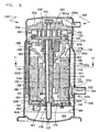
- Figure 1 is a cross-sectional view of a scroll compressor according to one embodiment of the invention.
- Figure 2 is a cross-sectional view taken along line 2-2 of Figure 1 .
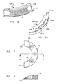
- Figure 3 is a perspective view of a suction line oil trap.
- Figure 4 is a cross-sectional view taken along line 4-4 of Figure 2 .
- Figure 5 is an end view looking upstream at the suction line oil trap of Figure 3 .
- Figure 6a is a perspective view of a diffuser.
- Figure 6b is a perspective view of an alternative diffuser.
- Figure 7 is a bottom view of a streamlined counterweight.
- Figure 8 is a cross-sectional view taken along line 8-8 of Figure 7 .
- Figure 9 is a cross-sectional view of a scroll compressor according to another embodiment of the invention.
- Figure 10 is cross-sectional view similar to Figure 12 but with the motor sleeve not being cross-sectioned.
- Figure 11 is a cross-sectional view taken along line 11-11 of Figure 9 .
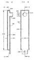
- Figure 12 is a cross-sectional view taken along line 12-12 of Figure 13 and showing an oil drain tube.
- Figure 13 is a cross-sectional view taken along line 13-13 of Figure 12 .
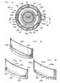
- Figure 14 is a perspective view of a suction baffle.
- Figure 15 is a perspective view of another suction baffle.
- Figure 16 is a perspective view of another suction baffle.
- FIGS 1 and 2 show cross-sectional views of a scroll compressor 10 having gas and oil flow patterns that minimize oil entrainment. It should be noted that the terms, “oil” and “lubricant” both refer to any fluid that helps reduce friction.
- Scroll compressor 10 comprises a driven scroll member 12 with a scroll wrap 14 that interleaves a similar scroll wrap 16 of another scroll member 18.
- the two scroll wraps define several compression chambers, such as chambers 20 and 22, for compressing a refrigerant or other type of gas, air for instance.
- a motor 24 drives scroll member 12 in an orbital motion relative to scroll member 18.
- the relative movement between the two scroll members forces the compression chambers to spiral toward a discharge opening 26 of scroll member 18.
- the volumes of the compression chambers decrease, thereby compressing the gas trapped within the chambers.
- gas 28 enters compressor 10, flows to and enters the scroll wraps near the outer perimeters of scroll members 12 and 18, and exits compressor 10, at a higher pressure, through discharge opening 26.
- compressor 10 The main components of compressor 10 are contained within a compressor shell 30 having a suction inlet 32 for receiving gas at a relatively low pressure and an outlet 34 for discharging gas at a higher pressure.
- the upper interior portion 35a of shell 30 is referred to as the discharge pressure portion or high side of the compressor, while lower interior portion 35b is referred to as the low side or suction pressure portion of the compressor.
- motor 24 includes a stator 36 for creating a magnetic field, a rotor 38 rotated by the magnetic field and defining a rotor gap 40 between the stator and the rotor, a counterweight 42 attached to a lower end of rotor 38 for dynamic balance, and a rotor shaft 44 extending through rotor 38 and coupled by an eccentric bearing 46 to drive scroll member 12 in an orbital motion.
- a lower bearing housing 48 includes a lower bearing system 50 for radially and axially supporting rotor 38 and shaft 44 on which rotor 38 is mounted.
- An upper bearing housing 52 includes an upper bearing 54 for radially supporting rotor 38 and shaft 44 on which rotor 38 is mounted.
- Upper bearing housing 52 also includes a thrust bearing surface 56 for vertically supporting orbital scroll member 12.
- Rotor shaft 38 defines an inclined oil gallery 58 that conveys oil 60 (or another type of lubricant) up from an oil sump 62 at the bottom of shell 30 and delivers the oil to various moving parts of the compressor.
- Such moving parts include, but are not limited to, lower bearing system 50, upper bearing 54, eccentric bearing 46, thrust bearing surface 56, and an anti-rotation device 64 that maintains a proper angular relationship between scroll members 12 and 18.
- Centrifugal force created by inclined, radially offset oil gallery 58 and/or an impeller.at the lower end of shaft 44 provides the impetus to move the oil upward through an oil inlet 66 that is submerged in oil sump 62.
- Oil passageway 70 whose length to diameter ratio is at least three extends radially (either horizontally or slightly inclined as shown) through bearing housing 52. The extended length of passageway 70 enables the passageway to convey oil 60 from within cavity 68 and direct the oil near or onto an inner surface 72 of compressor shell 30. Oil passageway 70 is an integral feature of bearing housing 52. After leaving passageway 70, the oil drains along surface 72, through the open areas defined in lower bearing housing 48, and into sump 62.
- the location of the oil return paths in relation to the gas flow pattern within compressor shell 30 can significantly affect how much oil the gas entrains.
- the gas exiting the compressor contains less than one percent by mass of entrained oil.
- the gas 28 is directed through the compressor in a strategic manner.
- Oil trap 74 includes a suction tube 76 leading to suction inlet 32, an orifice plate 78 extending radially inward from suction tube 76 for restricting gas flow therethrough, and a flow divider 80 extending from orifice plate 78 in an upstream direction through tube 76.
- the orifice plate defines an opening 82 through which substantially all of the gas and oil within suction tube 76 eventually passes.
- Orifice plate 78 can be crescent-shaped and situated such that the location of opening 82 is offset toward a lower portion of suction tube 76.
- Flow divider 80 may assume various shapes. For example, in some embodiments, flow divider 80 has a semi-cylindrical shape with lower edges 84 that are spaced apart from suction tube 76.
- suction tube 76 has an inner wall 86 that diverges but at an angle 88 of less than twenty degrees. If angle 88 is too large, oil droplets are less likely to cling to the tapered wall 86. To maintain gas/oil separation and surface-clinging ability, angle 88 is preferably at seven degrees.
- the flow restriction provided by orifice plate 78 further ensures oil/gas separation. With the combined effects of tapered wall 86 and orifice plate 78, oil tends to be separated from the gas flow and cling to wall 86 and is directed toward a lower portion of tube 76.
- orifice plate 78 inhibits oil from being flowing directly into shell 30. Instead, that oil flows downward along the curved upper surface of flow divider 80 until the oil descends below the divider's lower edges 84 and reaches opening 82 near the bottom of tube 76.
- a first portion of gas 28a travels upward while a second portion of gas 28b travels downward and carries the disentrained oil downward toward sump 62.
- the amount of gas that travels downward is reduced which, in turn, reduces the gas flow velocity near sump 62.
- the vertically bifurcated gas flow pattern entering shell 30 is due to the suction inlet's position relative to the location of a first gas passageway 90 and a second gas passageway 92 that are defined between a stator core 94 and shell 30.
- Stator core 94 is a laminated ferrous portion of stator 36 that helps concentrate the magnetic field that is generated by electrical current passing through the windings of stator 36.
- Upper end turns 96 of the windings extend above core 36 and lower end turns 98 extend below core 36.
- gas passageways 90 and 92 are slots that run vertically along stator core 94. Between the slots, the outer diameter of core 94 is in substantial abutment with the inner wall 72 of shell 30.
- the first portion of gas 28a travels upward through gas passageway 90 to help cool upper end turns 96 before entering one or more inlets 100 in bearing housing 52. From inlets 100, the gas enters the scroll wraps to be compressed.
- Bearing housing 52 preferably has two inlets 100 that are circumferentially 180-degrees apart from each other and circumferentially 90-degrees offset to suction inlet 32. Such an arrangement promotes a gas flow pattern that "wraps" around upper end turns 96 for more evenly distributed cooling.
- the first portion of gas 28a may be quite cool as that portion of the gas will not have been preheated by flow past the lower end turns 98.
- diffuser 102 includes an upper baffle 104 and a lower baffle 105 that redirect the gas flow more horizontally.
- the two baffles 104 and 105 can be joined to each other by a surface 106 and attached to stator core 90, as shown, or the baffles may be separate parts with one attached to stator 94 and the other attached to shell 30.
- One or more apertures 107 provide a flow path for gas through the diffuser. The same description applies with respect to the alternate embodiment of Figure 6b and its baffles 104a and 105a, surface 106a and aperture 107a.
- the second portion of gas 28b passes underneath stator 36 to cool lower end turns 98.
- the second portion of gas 28b divides into a third portion of gas 28c that travels upward through second gas passageway 92 and a fourth portion of gas 28d that travels upward through rotor gap 40.
- the second portion of gas 28b flowing downward through the first gas passageway 90 flows at a mass flow rate that is substantially equal to the combined mass flow rate of gas passing through the second gas flow passageway 92 and rotor gap 40.
- the first gas passageway 90 conveys more gas than does the second gas passageway 92, and passageway 92 conveys more gas than does rotor gap 40.
- stator 36 Near the upper portion of stator 36, the various portions of gas intermix, and substantially all the intermixed gas 28e passes through inlets 100 of upper bearing housing 52 to enter the chambers between the scroll wraps. That gas is compressed, flows through discharge opening 26 and exits the compressor as discharge pressure gas 28f which flows through outlet 34.
- counterweight 42 can be provided with a streamlined nose 108 and a streamlined tail 110 that minimizes the turbulence.
- counterweight 42 is shown having a beveled leading edge 112 and a beveled trailing edge 114 that lie at an angle relative to a rotational axis 116 of rotor 44.
- a scroll compressor 130 in another embodiment, shown in Figures 9 , 10 and 11 , includes a motor 132 surrounded by a motor sleeve 134.
- a generally cylindrical suction chamber 136 is defined between sleeve 134 and compressor shell 138.
- Compressor 130 includes a discharge pressure portion or high side 139a within shell 138 as well as a suction pressure portion or low side 139b therein.
- a first gas passageway 140 and a second gas passageway 142 are defined between the interior of sleeve 134 and the exterior of motor stator 144.
- motor sleeve 134 defines upper apertures 146 and lower apertures 148 through which gas flows to the interior of sleeve 134 and the lower end of sleeve 134 is blocked off by a lower bearing housing 150.
- the interior of sleeve 134 is therefor shielded and/or isolated from the oil sump which lies beneath it, as will subsequently be described.
- compressor 130 includes a driven scroll member 150 with a scroll wrap 152 that interleaves a similar scroll wrap 154 of another scroll member 156.
- the two scroll wraps define several compression chambers, such as chambers 158 and 160, for compressing a refrigerant or other type of gas.
- Motor 132 drives scroll member 150 in an orbital motion relative to scroll member 156.
- the relative movement between the two scroll members forces the compression chambers to spiral toward a discharge opening 162 of scroll member 156.
- the volumes of the compression chambers decrease, thereby compressing the gas trapped within the chambers.
- Gas 164 enters the compressor, flows to the scroll wraps near the outer perimeter thereof, is compressed and exits the compressor at a higher pressure through discharge opening 162.
- the main components of compressor 130 are contained within compressor shell 138 which has a suction inlet 166 for receiving gas 164 at a relatively low pressure and an outlet 168 for discharging the gas at a higher pressure.
- motor 132 To drive scroll member 150, motor 132 includes stator 144 for creating a magnetic field, a rotor 170 rotated by the magnetic field and defining a rotor gap 172 between the stator and the rotor, a counterweight 174 attached to a lower end of rotor 170 for dynamic balance, and a rotor shaft 172 centrally located on rotor 170 and coupled by an eccentric bearing 174 to drive scroll member 150 in an orbital motion.
- Lower bearing housing 150 includes a lower bearing system 176 for radially and axially supporting rotor 170 and shaft 172 on which the rotor is mounted.
- An upper bearing housing 178 includes an upper bearing 180 for radially supporting shaft 172 and rotor 170.
- Upper bearing housing 178 also includes a thrust bearing surface 182 for vertically supporting orbital scroll member 150.
- Rotor shaft 172 defines an inclined oil gallery 184 that conveys oil 186 (or another type of lubricant) up from an oil sump 188 at the bottom of shell 138 and delivers the oil to various moving parts of the compressor.
- Such moving parts include, but are not limited to, lower bearing system 176, upper bearing 180, thrust bearing surface 182, and an anti-rotation device 190 that maintains a proper angular relationship between scroll members 150 and 156.
- Centrifugal force created by the rotation of shaft 172 and inclined, radially offset oil gallery 184 and/or an impeller at the lower end of shaft 172 provides the impetus to move the oil upward through an oil inlet 192 of shaft 172 that is submerged in the oil 186 in sump 188.
- oil may follow various paths back to sump 188.
- a substantial portion of oil 186 which lubricates and then leaves upper bearing 180 and eccentric bearing 180, drains into an inner cavity 196 of upper bearing housing 178.
- a drain tube 198 connected to an oil passageway 200 of bearing housing 178 drains the oil from cavity 196 into oil sump 188.
- a much smaller portion of oil leaving lower bearing system 176 and thrust bearing surface 182 may coat various surfaces within the compressor or become entrained by the gas flow that occurs within shell 138. Discharged entrained oil may eventually return to the suction side of the compressor.
- oil coating surfaces within motor sleeve 134 may also drain back into sump 188 from the interior of sleeve 134 via a drain hole 194 which is defined at the lower end thereof.
- drain tube 198 includes various features that enable it to effectively drain oil from cavity 196 while minimizing the oil's exposure to the flow of gas in suction pressure portion 139b of the compressor.
- Tube 198 for instance, has a length 202 that extends below lower apertures 148 of motor sleeve 134.
- An upper end 204 of tube 198 is capped, sealed or otherwise closed off.
- Tube 198 is also oblong ( Figure 11 ), which enables it to fit between compressor shell 138 and motor sleeve 134 while still providing an ample open area 206 for conveying oil.
- Area 206 is preferably equal to or larger than either the opening of oil passageway 200 or an opening in a short extension 208 that extends from tube 198.
- the inner diameter of oil passageway 200 is less than a maximum width 212 of area 206 and is greater than a minimum width 214.
- Mounting'tabs 216 and 218 enable conventional threaded fasteners to attach tube 198 to the side of bearing housing 178 and/or motor sleeve 134.
- Tube 198 is preferably offset circumferentially relative to lower and upper apertures 146 and 148 of sleeve 134 so as not to obstruct gas flow through those apertures.
- tube 198 is shown circumferentially disposed 180 degrees away from suction inlet 166, the actual location of tube 198 may be at any position around motor sleeve 134. In some embodiments, tube 198 is positioned between 90 and 180 degrees from inlet 166.
- the location of the oil return paths in relation to the gas flow pattern within compressor shell 138 can significantly affect how much oil the gas entrains in its flow through suction pressure portion 139b of shell 138 to the scroll members.
- the gas exiting compressor 130 contains less than one percent by mass of entrained oil.
- gas 164 is directed through the compressor in a strategic manner.
- baffle 220 includes a flow deflector plate 222 and a lower block-off 224 that cooperate to define a pocket 226 having an upper opening 228, such that baffle 220 deflects the incoming gas upward.
- deflector plate 222 curves away from motor sleeve 134 and toward suction inlet 166 to enable suction baffle 220 to fit within the narrow, cylindrically shaped space between sleeve 134 and shell 138.
- the curved shape also provides rigidity to plate 222 and helps divert and spread the flow of gas circumferentially around sleeve 134 although the deflector's side edges 230 are adjacent to compressor shell 138 to ensure that the gas flow direction is directed generally upward as well.
- the entrained oil may separate from the incoming suction gas.
- the disentrained oil may drain out of pocket 226 through one or more liquid drain passageways defined in baffle 220, so the oil can return to sump 188.
- the liquid drain passageways drain oil to the sump that might otherwise accumulate in pocket 226 at times when the compressor is inactive, particularly where the compressor is connected to a second running compressor via a manifold.
- the liquid drain passageways are holes 232 near the outside bottom corners of deflector plate 220.
- baffle 220b in the embodiment of Figure 15 , the liquid drain passageways of baffle 220b are provided by elongate channels 234 formed into plate 222a, whereby the oil can drain through channel 234 between plate 222a and shell 138.
- baffle 220b includes a flow deflector plate 222b, mounting edges 230b, and mounting tabs 233. In this case, slots 235 provide the liquid drain passageway.
- deflector plate 222b is generally more planar for use in compressors having sufficient space between the motor sleeve and the outer shell.
- the suction gas after being deflected by suction baffle 220, the suction gas generally separates into two swirling flow streams which follow flow paths 236 and 238, with one being generally the mirror image of the other.
- the two gas flow paths 236 and 238 lie within suction chamber 136 of suction pressure portion 139b of compressor 130 and are generally on opposite sides of motor sleeve 134. Each flow path generally rises above upper apertures 146 and then descends below lower apertures 148.
- Flow path 236 travels partially around the circumference of motor sleeve 134 in a generally clockwise direction (about the rotor's rotational axis 185 as viewed from above in Fig.
- the swirling flow patterns 236 and 238 are created by a number of the compressor's features that include, but are not limited to, the size, shape and location of apertures 146 and 148; the vertical spacing between apertures 146 and 148; the shape of suction chamber 136; the location of suction inlet 166 relative to apertures 146 and 148; and the geometry of suction baffle 220.
- Substantially all of the gas 164 that enters suction pressure portion 139b of shell 138 passes through the combination of apertures 146 and 148 to move from suction chamber 136 to the interior of sleeve 134 where the gas flow cools motor 132 before entering the scroll wraps.
- a first portion of gas 164a travels sequentially through suction inlet 166, suction chamber 136, upper apertures 146, across motor upper end turns 240 (which helps cool the end turns).
- the gas then flows through one or more apertures 242 ( Figs. 9 and 10) of bearing housing 178, and to and between scroll wraps 152 and 154. From there the gas is compressed, is discharged into discharge pressure portion 139a of the compressor shell and exits the compressor through outlet 168 as gas stream 164d.
- Suction inlet 166 is preferably disposed circumferentially between two of the upper apertures 146 in sleeve 134.
- the path of first portion of gas 164a causes less than all of the gas that enters suction pressure portion 139b of compressor 130 to circulate past sump 188.
- upper apertures 146 divert gas that might otherwise increase the gas flow velocity near sump 188.
- sump turbulence is reduced which, in turn, reduces the amount of oil that becomes entrained by the gas flow stream within the compressor.
- gas passageways 140 and 142 are slots that run vertically along a stator core 244 of stator 144. Between the slots, the outer diameter of core 244 substantially abuts the inner surface of motor sleeve 134. The slots are preferably circumferentially offset relative to upper apertures 146.
- a third portion of gas 164c travels sequentially through suction inlet 166, through lower aperture 148, downward between motor sleeve 134 and lower end turns 246, upward through rotor gap 172, and between the two scroll wraps 152 and 154.
- the lower apertures 148 are arranged in four pairs with each pair being generally centered beneath an upper aperture 146. This ensures that the first portion of gas 164a is less than a sum of the second portion of gas 164b plus the third portion of gas 164c. Also, the second portion of gas 164b is greater than the third portion of gas 164c.
- upper apertures 146 are open to an area between upper end turns 240 and an upper edge of stator core 244, and lower apertures 148 are open to an area between lower end turns 246 and a lower edge of core 244.
- compressor 130 can be applied to compressor 10 and vice versa.
- the features may pertain to various adaptable components including, but not limited to, suction line oil trap 74, suction baffle 220, oil drain tube 198, motor sleeve 134, bearing housings 52 and 178, diffuser 102, and counterweight 42.
- suction line oil trap 74 suction line oil trap 74
- suction baffle 220 suction baffle 220
- oil drain tube 198 oil drain tube 198
- motor sleeve 134 bearing housings 52 and 178
- diffuser 102 diffuser 102
Landscapes
- Engineering & Computer Science (AREA)
- Mechanical Engineering (AREA)
- General Engineering & Computer Science (AREA)
- Rotary Pumps (AREA)
- Applications Or Details Of Rotary Compressors (AREA)
Description
- The present invention relates to scroll compressors and more specifically to structure that helps direct and separate the flow of gas and lubricant through the compressor.
- Scroll compressors, such as disclosed in
JP 2-215982 - To minimize wear, scroll compressors usually have an oil pump that draws oil from an oil sump at the bottom of the compressor shell and forces the oil to various bearings and other moving parts of the compressor. Afterwards, the oil drains back to the oil sump for reuse. The pump is usually incorporated into a rotor shaft of a motor whose primary function is to drive the movement of one or both of the scroll members.
- Since the gas and oil are in open fluid communication with each other, the gas may entrain some of the oil. Then, as the compressor discharges the compressed gas, the entrained oil is discharged as well, thus reducing the level of oil in the sump. The oil may eventually return to the compressor through a suction inlet of the compressor shell; however, if the discharged gas entrains an excessive amount of oil,'the compressor may be left with an insufficient amount of oil in the sump.
- Various conditions can cause the gas to entrain an excessive amount of oil. More oil is entrained, for instance, when gas moves at high velocity across the surface of the oil in the sump. Also, a protruding counterweight or other irregularity at the lower end of the rotor may create a gas vortex or turbulence that can agitate the oil in the sump. High velocity gas tends to entrain oil more readily from oil surfaces that are more agitated. In some cases, the oil returning to the sump may be opposed by a strong current of gas moving in an opposite direction away from the sump. The counter flow pattern of oil and gas tends to entrain more oil. Thus, it may be beneficial to separate the gas and oil flow paths as much as possible.
- Keeping the gas flow completely away from the oil sump may reduce oil entrainment but may also create an overheating problem within the motor. Since the motor's rotor shaft usually serves as the pump and as a conduit for conveying the oil from the sump to the parts needing lubrication, the motor is preferably adjacent to the sump. This usually places the oil sump and the lower end turns of the motor's stator in proximity. Directing the gas away from the sump and thus away from the lower end turns of the motor may prevent the gas from being able to cool the lower end turns. As a result, the motor may overheat.
- Consequently, there is a need for a scroll compressor that provides effective gas/oil separation without sacrificing motor cooling.
-
US 6,247,907 discloses a sealed compressor that incorporates a relatively thin counterweight. The relatively thin counterweight is able to fit within a much smaller space than prior art cast counterweights. The relatively thin counterweight allows the reduction of the overall length of the sealed compressor. - It is an object of some embodiments of the present invention is to provide a scroll compressor that provides effective gas/oil separation and sufficient motor cooling.
- It is an object of some embodiments to reduce the gas flow near an oil sump of a scroll compressor.
- It is an object of some embodiments to reduce the gas flow near an oil sump of a scroll compressor by diverting some of the incoming gas in an upward direction away from the oil sump.
- It is an object of some embodiments to provide a scroll compressor with a motor sleeve that includes apertures at strategic locations for creating a desirable gas flow pattern.
- It is an object of some embodiments to block off the lower end of a motor sleeve to help shelter the oil sump from high velocity gas flow.
- It is an object of some embodiments to reduce the extent to which return oil is exposed to upwardly moving gas by connecting an oil drain tube to a scroll compressor's bearing housing.
- It is an object of some embodiments to provide a scroll compressor with a suction baffle adjacent to a suction inlet of the compressor's outer shell, wherein the baffle directs the incoming gas upward through a suction chamber that is between a motor sleeve and the outer shell.
- It is an object of some embodiments to provide the suction baffle with oil drain holes that are spaced apart from each other to drain oil from opposite ends of the baffle.
- It is an object of some embodiments to provide a motor sleeve with upper apertures that direct a portion of the gas toward the upper end turns of a stator to cool those end turns, and so there is less gas available to flow near the oil sump.
- It is an object of some embodiments to provide a motor sleeve with apertures of various size and location to distribute the gas flow in proper proportions through and around the motor.
- It is an object of some embodiments to discharge from a scroll compressor a mixture of gas and oil, wherein the mass flow rate of the oil is less than one percent of the total mass flow rate discharged from the compressor.
- It is an object of some embodiments to provide a scroll compressor whose incoming gas is divided into two portions, wherein one portions flows upward and the other flows downward upon first entering the compressor shell.
- It is an object of some embodiments to swirl the gas flow in a circular pattern across upper and lower apertures of a motor sleeve.
- It is an object of some embodiments to provide a scroll compressor with a suction inlet and a motor sleeve with apertures, wherein the suction inlet is circumferentially offset relative to the apertures to promote a desired gas flow pattern.
- It is an object of some embodiments to provide slots in a stator core for conveying gas, and circumferentially offsetting the location of the slots relative to apertures in a motor sleeve to promote a desired gas flow pattern.
- It is an object of some embodiments to position apertures in a motor sleeve such that the apertures direct gas flow in areas between the stator's core and its end turns.
- It is an object of some embodiments to combine the use of a motor sleeve and an oil drain tube to avoid excessive mixing of oil and gas.
- It is an object of some embodiments to provide an oil return path that include a round hole in fluid communication with an oblong drain tube, wherein the round hole is relatively easy to produce, and the oblong drain tube more readily fits between a motor sleeve and a compressor shell than would a round tube of a diameter equal to or greater than the round hole.
- It is an object of some embodiments to provide two gas flow passageways between a stator and a compressor shell, wherein gas flows upward through one passageway and splits into upward and downward flow directions through the other.
- It is an object of some embodiments to provide a scroll compressor with a bearing housing that includes a cast-in, radially extended oil passageway that reduces the extent to which return oil is exposed to upwardly moving gas.
- It is an object of some embodiments to cool the upper end turns of a stator with gas that has not been preheated by the lower end turns.
- It is an object of some embodiments to position a suction inlet closer to the upper end turns than to the lower end turns.
- It is an object of some embodiments to circumferentially offset the position of the suction inlet relative to a gas flow inlet of an upper bearing housing.
- It is an object of some embodiments to apportion the gas across various paths within a compressor shell to minimize oil entrainment.
- It is an object of some embodiments to promote oil/gas separation by a combined method of flow restriction and gas expansion.
- It is an object of some embodiments to provide a streamlined counterweight to reduce turbulence near an oil sump.
- It is an object of some embodiments to provide a compressor with a diffuser that has vertically and horizontally offset baffles that redirect the gas flow near the lower end of the compressor's motor.
- One or more of the above-listed objects of the invention are provided by a scroll compressor wherein two gas passageways are defined between the stator and a compressor shell or between the stator and a motor sleeve. Gas is directed through the compressor shell in a bifurcated flow pattern that reduces the velocity of gas flowing adjacent to an oil sump at the bottom of the shell, which helps reduce the amount of oil entrainment.
-
Figure 1 is a cross-sectional view of a scroll compressor according to one embodiment of the invention. -
Figure 2 is a cross-sectional view taken along line 2-2 ofFigure 1 . -
Figure 3 is a perspective view of a suction line oil trap. -
Figure 4 is a cross-sectional view taken along line 4-4 ofFigure 2 . -
Figure 5 is an end view looking upstream at the suction line oil trap ofFigure 3 . -
Figure 6a is a perspective view of a diffuser. - Figure 6b is a perspective view of an alternative diffuser.
-
Figure 7 is a bottom view of a streamlined counterweight. -
Figure 8 is a cross-sectional view taken along line 8-8 ofFigure 7 . -
Figure 9 is a cross-sectional view of a scroll compressor according to another embodiment of the invention. - Figure 10 is cross-sectional view similar to
Figure 12 but with the motor sleeve not being cross-sectioned. -
Figure 11 is a cross-sectional view taken along line 11-11 ofFigure 9 . -
Figure 12 is a cross-sectional view taken along line 12-12 ofFigure 13 and showing an oil drain tube. -
Figure 13 is a cross-sectional view taken along line 13-13 ofFigure 12 . -
Figure 14 is a perspective view of a suction baffle. -
Figure 15 is a perspective view of another suction baffle. -
Figure 16 is a perspective view of another suction baffle. -
Figures 1 and2 show cross-sectional views of ascroll compressor 10 having gas and oil flow patterns that minimize oil entrainment. It should be noted that the terms, "oil" and "lubricant" both refer to any fluid that helps reduce friction. -
Scroll compressor 10 comprises a drivenscroll member 12 with ascroll wrap 14 that interleaves asimilar scroll wrap 16 of anotherscroll member 18. The two scroll wraps define several compression chambers, such aschambers motor 24 drives scrollmember 12 in an orbital motion relative to scrollmember 18. The relative movement between the two scroll members forces the compression chambers to spiral toward adischarge opening 26 ofscroll member 18. As the compression chambers approachdischarge opening 26, the volumes of the compression chambers decrease, thereby compressing the gas trapped within the chambers. As will be described in more detail below,gas 28 enterscompressor 10, flows to and enters the scroll wraps near the outer perimeters ofscroll members compressor 10, at a higher pressure, throughdischarge opening 26. The main components ofcompressor 10 are contained within acompressor shell 30 having asuction inlet 32 for receiving gas at a relatively low pressure and anoutlet 34 for discharging gas at a higher pressure. The upper interior portion 35a ofshell 30 is referred to as the discharge pressure portion or high side of the compressor, while lowerinterior portion 35b is referred to as the low side or suction pressure portion of the compressor. - To drive
scroll member 12,motor 24 includes astator 36 for creating a magnetic field, arotor 38 rotated by the magnetic field and defining arotor gap 40 between the stator and the rotor, acounterweight 42 attached to a lower end ofrotor 38 for dynamic balance, and arotor shaft 44 extending throughrotor 38 and coupled by aneccentric bearing 46 to drivescroll member 12 in an orbital motion. Alower bearing housing 48 includes alower bearing system 50 for radially and axially supportingrotor 38 andshaft 44 on whichrotor 38 is mounted. An upper bearinghousing 52 includes anupper bearing 54 for radially supportingrotor 38 andshaft 44 on whichrotor 38 is mounted. Upper bearinghousing 52 also includes athrust bearing surface 56 for vertically supportingorbital scroll member 12. -
Rotor shaft 38 defines aninclined oil gallery 58 that conveys oil 60 (or another type of lubricant) up from anoil sump 62 at the bottom ofshell 30 and delivers the oil to various moving parts of the compressor. Such moving parts include, but are not limited to,lower bearing system 50,upper bearing 54,eccentric bearing 46,thrust bearing surface 56, and ananti-rotation device 64 that maintains a proper angular relationship betweenscroll members oil gallery 58 and/or an impeller.at the lower end ofshaft 44 provides the impetus to move the oil upward through anoil inlet 66 that is submerged inoil sump 62. - After lubricating the compressor's moving parts, the oil may follow various paths back to
sump 62. The oil leavinglower bearing system 50 drains intosump 62 by passing through open areas defined inlower bearing housing 48. A greater portion ofoil 60, which is delivered throughgallery 58, lubricates and then leavesupper bearing 54,thrust bearing surface 56 andeccentric bearing 46 and drains into aninner cavity 68 of upper bearinghousing 52. Anoil passageway 70 whose length to diameter ratio is at least three extends radially (either horizontally or slightly inclined as shown) through bearinghousing 52. The extended length ofpassageway 70 enables the passageway to conveyoil 60 from withincavity 68 and direct the oil near or onto aninner surface 72 ofcompressor shell 30.Oil passageway 70 is an integral feature of bearinghousing 52. After leavingpassageway 70, the oil drains alongsurface 72, through the open areas defined inlower bearing housing 48, and intosump 62. - The location of the oil return paths in relation to the gas flow pattern within
compressor shell 30 can significantly affect how much oil the gas entrains. Preferably, the gas exiting the compressor contains less than one percent by mass of entrained oil. To achieve this, thegas 28 is directed through the compressor in a strategic manner. -
Gas 28 enteringsuction inlet 32, for instance, passes through anoil trap 74, which is shown in greater detail inFigures 3, 4, and 5 .Oil trap 74 includes asuction tube 76 leading tosuction inlet 32, anorifice plate 78 extending radially inward fromsuction tube 76 for restricting gas flow therethrough, and aflow divider 80 extending fromorifice plate 78 in an upstream direction throughtube 76. The orifice plate defines anopening 82 through which substantially all of the gas and oil withinsuction tube 76 eventually passes.Orifice plate 78 can be crescent-shaped and situated such that the location of opening 82 is offset toward a lower portion ofsuction tube 76.Flow divider 80 may assume various shapes. For example, in some embodiments, flowdivider 80 has a semi-cylindrical shape withlower edges 84 that are spaced apart fromsuction tube 76. - To maintain or enhance gas/oil separation,
suction tube 76 has aninner wall 86 that diverges but at anangle 88 of less than twenty degrees. Ifangle 88 is too large, oil droplets are less likely to cling to the taperedwall 86. To maintain gas/oil separation and surface-clinging ability,angle 88 is preferably at seven degrees. The flow restriction provided byorifice plate 78 further ensures oil/gas separation. With the combined effects of taperedwall 86 andorifice plate 78, oil tends to be separated from the gas flow and cling to wall 86 and is directed toward a lower portion oftube 76. - Above
flow divider 80,orifice plate 78 inhibits oil from being flowing directly intoshell 30. Instead, that oil flows downward along the curved upper surface offlow divider 80 until the oil descends below the divider'slower edges 84 and reaches opening 82 near the bottom oftube 76. Upon enteringshell 30, a first portion of gas 28a travels upward while a second portion ofgas 28b travels downward and carries the disentrained oil downward towardsump 62. By directing a first portion of gas 28a upward upon its entry intoshell 30, the amount of gas that travels downward is reduced which, in turn, reduces the gas flow velocity nearsump 62. - The vertically bifurcated gas flow
pattern entering shell 30 is due to the suction inlet's position relative to the location of afirst gas passageway 90 and asecond gas passageway 92 that are defined between astator core 94 andshell 30.Stator core 94 is a laminated ferrous portion ofstator 36 that helps concentrate the magnetic field that is generated by electrical current passing through the windings ofstator 36. Upper end turns 96 of the windings extend abovecore 36 and lower end turns 98 extend belowcore 36. In some embodiments,gas passageways stator core 94. Between the slots, the outer diameter ofcore 94 is in substantial abutment with theinner wall 72 ofshell 30. By positioningsuction inlet 32 vertically between upper end turns 96 and lower end turns 98, the incoming gas tends to divide into first andsecond portions 28a and 28b. - The first portion of gas 28a travels upward through
gas passageway 90 to help cool upper end turns 96 before entering one ormore inlets 100 in bearinghousing 52. Frominlets 100, the gas enters the scroll wraps to be compressed. Bearinghousing 52 preferably has twoinlets 100 that are circumferentially 180-degrees apart from each other and circumferentially 90-degrees offset tosuction inlet 32. Such an arrangement promotes a gas flow pattern that "wraps" around upper end turns 96 for more evenly distributed cooling. Moreover, the first portion of gas 28a may be quite cool as that portion of the gas will not have been preheated by flow past the lower end turns 98. - The second portion of
gas 28b travels fromsuction inlet 32 downward throughfirst gas passageway 90. To avoid the second portion ofgas 28b from "blasting" directly downward against the surface ofoil 60 insump 62, adiffuser 102 is installed at a lower end ofgas passageway 90. Referring toFigure 6a ,diffuser 102 includes anupper baffle 104 and alower baffle 105 that redirect the gas flow more horizontally. The twobaffles surface 106 and attached tostator core 90, as shown, or the baffles may be separate parts with one attached tostator 94 and the other attached to shell 30. One ormore apertures 107 provide a flow path for gas through the diffuser. The same description applies with respect to the alternate embodiment of Figure 6b and its baffles 104a and 105a, surface 106a andaperture 107a. - The second portion of
gas 28b passes underneathstator 36 to cool lower end turns 98. The second portion ofgas 28b divides into a third portion ofgas 28c that travels upward throughsecond gas passageway 92 and a fourth portion ofgas 28d that travels upward throughrotor gap 40. Hence, the second portion ofgas 28b flowing downward through thefirst gas passageway 90 flows at a mass flow rate that is substantially equal to the combined mass flow rate of gas passing through the secondgas flow passageway 92 androtor gap 40. Thefirst gas passageway 90 conveys more gas than does thesecond gas passageway 92, andpassageway 92 conveys more gas than doesrotor gap 40. Near the upper portion ofstator 36, the various portions of gas intermix, and substantially all the intermixedgas 28e passes throughinlets 100 of upper bearinghousing 52 to enter the chambers between the scroll wraps. That gas is compressed, flows throughdischarge opening 26 and exits the compressor asdischarge pressure gas 28f which flows throughoutlet 34. - Since gas turbulence near the bottom of the compressor can agitate the surface of the oil in
sump 62,counterweight 42 can be provided with astreamlined nose 108 and astreamlined tail 110 that minimizes the turbulence. InFigures 7 and 8 ,counterweight 42 is shown having a beveled leadingedge 112 and abeveled trailing edge 114 that lie at an angle relative to arotational axis 116 ofrotor 44. - In another embodiment, shown in
Figures 9 , 10 and11 , ascroll compressor 130 includes amotor 132 surrounded by amotor sleeve 134. A generallycylindrical suction chamber 136 is defined betweensleeve 134 andcompressor shell 138.Compressor 130 includes a discharge pressure portion orhigh side 139a withinshell 138 as well as a suction pressure portion orlow side 139b therein. Referring especially toFigure 11 , afirst gas passageway 140 and asecond gas passageway 142 are defined between the interior ofsleeve 134 and the exterior ofmotor stator 144. To minimize the mixing of oil and gas,motor sleeve 134 definesupper apertures 146 andlower apertures 148 through which gas flows to the interior ofsleeve 134 and the lower end ofsleeve 134 is blocked off by alower bearing housing 150. The interior ofsleeve 134 is therefor shielded and/or isolated from the oil sump which lies beneath it, as will subsequently be described. - Similar to
compressor 10 embodiment ofFigures 1 and2 ,compressor 130 includes a drivenscroll member 150 with ascroll wrap 152 that interleaves asimilar scroll wrap 154 of anotherscroll member 156. The two scroll wraps define several compression chambers, such aschambers Motor 132 drives scrollmember 150 in an orbital motion relative to scrollmember 156. The relative movement between the two scroll members forces the compression chambers to spiral toward adischarge opening 162 ofscroll member 156. As the compression chambers approachdischarge opening 162, the volumes of the compression chambers decrease, thereby compressing the gas trapped within the chambers.Gas 164 enters the compressor, flows to the scroll wraps near the outer perimeter thereof, is compressed and exits the compressor at a higher pressure throughdischarge opening 162. The main components ofcompressor 130 are contained withincompressor shell 138 which has asuction inlet 166 for receivinggas 164 at a relatively low pressure and anoutlet 168 for discharging the gas at a higher pressure. - To drive
scroll member 150,motor 132 includesstator 144 for creating a magnetic field, arotor 170 rotated by the magnetic field and defining arotor gap 172 between the stator and the rotor, acounterweight 174 attached to a lower end ofrotor 170 for dynamic balance, and arotor shaft 172 centrally located onrotor 170 and coupled by aneccentric bearing 174 to drivescroll member 150 in an orbital motion.Lower bearing housing 150 includes alower bearing system 176 for radially and axially supportingrotor 170 andshaft 172 on which the rotor is mounted. Anupper bearing housing 178 includes anupper bearing 180 for radially supportingshaft 172 androtor 170. Upper bearinghousing 178 also includes athrust bearing surface 182 for vertically supportingorbital scroll member 150. -
Rotor shaft 172 defines aninclined oil gallery 184 that conveys oil 186 (or another type of lubricant) up from anoil sump 188 at the bottom ofshell 138 and delivers the oil to various moving parts of the compressor. Such moving parts include, but are not limited to,lower bearing system 176,upper bearing 180, thrustbearing surface 182, and ananti-rotation device 190 that maintains a proper angular relationship betweenscroll members shaft 172 and inclined, radially offsetoil gallery 184 and/or an impeller at the lower end ofshaft 172 provides the impetus to move the oil upward through anoil inlet 192 ofshaft 172 that is submerged in theoil 186 insump 188. - After lubricating the compressor's moving parts, the oil may follow various paths back to
sump 188. A substantial portion ofoil 186, which lubricates and then leavesupper bearing 180 andeccentric bearing 180, drains into aninner cavity 196 of upper bearinghousing 178. Adrain tube 198 connected to an oil passageway 200 of bearinghousing 178 drains the oil fromcavity 196 intooil sump 188. A much smaller portion of oil leavinglower bearing system 176 and thrustbearing surface 182 may coat various surfaces within the compressor or become entrained by the gas flow that occurs withinshell 138. Discharged entrained oil may eventually return to the suction side of the compressor. When the compressor is de-energized, oil coating surfaces withinmotor sleeve 134 may also drain back intosump 188 from the interior ofsleeve 134 via adrain hole 194 which is defined at the lower end thereof. - Referring additionally now to
Figures 12 and 13 ,drain tube 198 includes various features that enable it to effectively drain oil fromcavity 196 while minimizing the oil's exposure to the flow of gas insuction pressure portion 139b of the compressor.Tube 198, for instance, has alength 202 that extends belowlower apertures 148 ofmotor sleeve 134. Anupper end 204 oftube 198 is capped, sealed or otherwise closed off.Tube 198 is also oblong (Figure 11 ), which enables it to fit betweencompressor shell 138 andmotor sleeve 134 while still providing an ampleopen area 206 for conveying oil.Area 206 is preferably equal to or larger than either the opening of oil passageway 200 or an opening in ashort extension 208 that extends fromtube 198. - In some cases, the inner diameter of oil passageway 200 is less than a
maximum width 212 ofarea 206 and is greater than aminimum width 214.Mounting'tabs tube 198 to the side of bearinghousing 178 and/ormotor sleeve 134.Tube 198 is preferably offset circumferentially relative to lower andupper apertures sleeve 134 so as not to obstruct gas flow through those apertures. Althoughtube 198 is shown circumferentially disposed 180 degrees away fromsuction inlet 166, the actual location oftube 198 may be at any position aroundmotor sleeve 134. In some embodiments,tube 198 is positioned between 90 and 180 degrees frominlet 166. - The location of the oil return paths in relation to the gas flow pattern within
compressor shell 138 can significantly affect how much oil the gas entrains in its flow throughsuction pressure portion 139b ofshell 138 to the scroll members. Preferably, thegas exiting compressor 130 contains less than one percent by mass of entrained oil. To achieve this,gas 164 is directed through the compressor in a strategic manner. -
Gas 164 enterscompressor 130 through asuction inlet 166 that directs the flow toward asuction baffle 220. Referring additionally now toFigure 14 ,baffle 220 includes aflow deflector plate 222 and a lower block-off 224 that cooperate to define apocket 226 having anupper opening 228, such thatbaffle 220 deflects the incoming gas upward. As is best shown inFigure 11 ,deflector plate 222 curves away frommotor sleeve 134 and towardsuction inlet 166 to enablesuction baffle 220 to fit within the narrow, cylindrically shaped space betweensleeve 134 andshell 138. The curved shape also provides rigidity to plate 222 and helps divert and spread the flow of gas circumferentially aroundsleeve 134 although the deflector's side edges 230 are adjacent tocompressor shell 138 to ensure that the gas flow direction is directed generally upward as well. - Upon striking
deflector plate 222, some of the entrained oil may separate from the incoming suction gas. The disentrained oil may drain out ofpocket 226 through one or more liquid drain passageways defined inbaffle 220, so the oil can return tosump 188. More importantly, the liquid drain passageways drain oil to the sump that might otherwise accumulate inpocket 226 at times when the compressor is inactive, particularly where the compressor is connected to a second running compressor via a manifold. InFigure 14 , the liquid drain passageways areholes 232 near the outside bottom corners ofdeflector plate 220. In the embodiment ofFigure 15 , the liquid drain passageways ofbaffle 220b are provided byelongate channels 234 formed into plate 222a, whereby the oil can drain throughchannel 234 between plate 222a andshell 138. In another embodiment, shownFigure 16 ,baffle 220b includes aflow deflector plate 222b, mountingedges 230b, and mountingtabs 233. In this case,slots 235 provide the liquid drain passageway. Also,deflector plate 222b is generally more planar for use in compressors having sufficient space between the motor sleeve and the outer shell. - Referring once again to Figures 10 and
11 , after being deflected bysuction baffle 220, the suction gas generally separates into two swirling flow streams which followflow paths gas flow paths suction chamber 136 ofsuction pressure portion 139b ofcompressor 130 and are generally on opposite sides ofmotor sleeve 134. Each flow path generally rises aboveupper apertures 146 and then descends belowlower apertures 148. Flowpath 236 travels partially around the circumference ofmotor sleeve 134 in a generally clockwise direction (about the rotor'srotational axis 185 as viewed from above inFig. 14 ) and then reverses its rotation (again, about axis 185) near the bottom offlow path 236. Similarly, theother flow path 238 travels partially circumferentially aroundmotor sleeve 134 in a generally counterclockwise direction (about the rotor'srotational axis 185 as viewed from above inFig. 14 ) and then reverses its rotation (again, about axis 185) near the bottom offlow path 238. - The swirling
flow patterns apertures apertures suction chamber 136; the location ofsuction inlet 166 relative toapertures suction baffle 220. - Substantially all of the
gas 164 that enterssuction pressure portion 139b ofshell 138 passes through the combination ofapertures suction chamber 136 to the interior ofsleeve 134 where the gas flow coolsmotor 132 before entering the scroll wraps. A first portion of gas 164a travels sequentially throughsuction inlet 166,suction chamber 136,upper apertures 146, across motor upper end turns 240 (which helps cool the end turns). The gas then flows through one or more apertures 242 (Figs. 9 and 10) of bearinghousing 178, and to and between scroll wraps 152 and 154. From there the gas is compressed, is discharged intodischarge pressure portion 139a of the compressor shell and exits the compressor throughoutlet 168 asgas stream 164d. -
Suction inlet 166 is preferably disposed circumferentially between two of theupper apertures 146 insleeve 134. The path of first portion of gas 164a causes less than all of the gas that enterssuction pressure portion 139b ofcompressor 130 to circulatepast sump 188. Thus,upper apertures 146 divert gas that might otherwise increase the gas flow velocity nearsump 188. By lowering the gas velocity nearsump 188, sump turbulence is reduced which, in turn, reduces the amount of oil that becomes entrained by the gas flow stream within the compressor. - A second portion of gas 164b travels sequentially through
suction inlet 166, throughsuction chamber 136, throughlower apertures 148, upward throughgas passageways aperture 242, and between scroll wraps 152 and 154. In some embodiments,gas passageways stator core 244 ofstator 144. Between the slots, the outer diameter ofcore 244 substantially abuts the inner surface ofmotor sleeve 134. The slots are preferably circumferentially offset relative toupper apertures 146. - A third portion of
gas 164c travels sequentially throughsuction inlet 166, throughlower aperture 148, downward betweenmotor sleeve 134 and lower end turns 246, upward throughrotor gap 172, and between the two scroll wraps 152 and 154. - In some embodiments, there are four
upper apertures 146 that are each about 0.6cm by 3cm (0.25-inches high by 1.25-inches) wide, and there are eightlower apertures 148 that are each about 1.9cm by 3.8cm (0.75-inches high by 1.5-inches) wide. In other cases, the lower apertures are 3.8cm by 3.8cm (1.5 inches by 1.5 inches). Thelower apertures 148 are arranged in four pairs with each pair being generally centered beneath anupper aperture 146. This ensures that the first portion of gas 164a is less than a sum of the second portion of gas 164b plus the third portion ofgas 164c. Also, the second portion of gas 164b is greater than the third portion ofgas 164c. - To ensure well distributed cooling of end turns 240 and 246 occurs and to promote gas flow through
apertures upper apertures 146 are open to an area between upper end turns 240 and an upper edge ofstator core 244, andlower apertures 148 are open to an area between lower end turns 246 and a lower edge ofcore 244. - Although the invention is described with respect to a preferred embodiment, modifications thereto will be apparent to those skilled in the art. For example, many of the features of
compressor 130 can be applied tocompressor 10 and vice versa. The features may pertain to various adaptable components including, but not limited to, suctionline oil trap 74,suction baffle 220,oil drain tube 198,motor sleeve 134, bearinghousings diffuser 102, andcounterweight 42. The scope of the invention, therefore, is to be determined by reference to the following claims:
Claims (29)
- A scroll compressor (10) for compressing a gas, wherein the scroll compressor (10) is lubricated by a lubricant (60), the scroll compressor comprising:a compressor shell (30) defining a suction inlet (32);a first scroll member (12) disposed inside the compressor shell (30) and having a first scroll wrap;a second scroll member (18) disposed inside the compressor shell and having a second scroll wrap interleaved with the first scroll wrap;a stator (36) for creating a magnetic field, the stator (36) includes an upper end turns, a lower end turns, and a stator core (94) interposed therebetween, the stator (36) and compressor shell (30) define therebetween a first gas passageway (90) and a second gas passageway (92), wherein the first gas passageway (90) conveys the gas in both upward and downward directions while the second gas passageway (92) conveys the gas substantially only in an upward direction; anda rotor (38) disposed within the stator (36) to define a rotor gap therebetween, wherein the rotor (38) rotates in response to the magnetic field and is coupled to the second scroll member to drive the second scroll member (18) in an orbital motion relative to the first scroll member (12), thereby compressing the gas between the first scroll wrap and the second scroll wrap.
- The scroll compressor (10) of claim 1, wherein the first gas passageway (90) and the second gas passageway (92) are created by a first slot and a second slot in the stator (36).
- The scroll compressor (10) of claim 1, wherein the gas entering the compressor shell (30) via the suction inlet (32) divides into a first portion of gas (28a) that travels upward from the suction inlet (32) and a second portion of gas (28b) that travels downward from the suction inlet (32), and the second portion of gas further separates into a third portion of gas (28c) that travels upward through the second gas passageway (92) and a fourth portion of gas (28d) that travels upward through the rotor gap (40).
- The scroll compressor (10) of claim 1, wherein the upper end turns extend above the suction inlet (32) and the lower end turns extend below the suction inlet (32).
- The scroll compressor (10) of claim 1, wherein the stator core (94) extends above the suction inlet (32).
- The scroll compressor (10) of claim 1, wherein the suction inlet (32) is closer to the upper end turns than the lower end turns.
- The scroll compressor (10) of claim 1, further comprising an upper bearing housing (52) disposed inside the compressor shell (30) and radially supporting the rotor (38) underneath the first scroll member (12), wherein the bearing housing (52) defines a lubricant passageway (70) having a length to diameter ratio of at least three for directing the lubricant (60) against the compressor shell (30).
- The scroll compressor (10) of claim 1, further comprising an upper bearing housing (52) disposed inside the compressor shell (30) and radially supporting the rotor (38) underneath the first scroll member (12), wherein the bearing housing (52) defines a plurality of gas inlets (100) that place the suction inlet (32) in fluid communication with first scroll wrap and the second scroll wrap, wherein the plurality of gas inlets (100) and the suction inlet (32) are circumferentially offset to promote a divided gas flow pattern between the suction inlet (32) and the plurality of gas inlets (100).
- The scroll compressor (10) of claim 1, wherein the first gas passageway (90) conveys more of the gas than does the second gas passageway (92).
- The scroll compressor (10) of claim 1, wherein the second gas passageway (92) conveys more of the gas than does the rotor gap (40).
- The scroll compressor (10) of claim 1, wherein the gas flowing downward through the first gas passageway (90) flows at a mass flow rate that is substantially equal to a combined mass flow rate through the second gas passageway (92) and the rotor gap (40).
- The scroll compressor (10) of claim 1, further comprising an oil trap (74) that includes a suction tube (76) leading to the suction inlet (32), an orifice plate (78) extending radially inward from the suction tube (76) for restricting gas flow therethrough, and a flow divider (80) extending from the orifice plate (78) in an upstream direction through the suction tube (76), wherein the orifice plate (78) defines an opening through which substantially all of the gas (28) and the lubricant (60) within the suction tube (76) eventually passes therethrough, wherein the location of the opening is biased toward a lower portion of the suction tube (76).
- The scroll compressor (10) of claim 12, wherein the flow divider (80) has a semi-cylindrical shape.
- The scroll compressor (10) of claim 13, wherein the flow divider (80) has two lower edges that are spaced apart from the suction tube (76).
- The scroll compressor (10) of claim 12, wherein the suction tube (76) includes an inner wall (86) that is tapered at an angle greater than zero but less than twenty degrees as measured relative to a longitudinal centreline of the suction tube, such that the gas expands upon moving in a downstream direction through the suction tube (76).
- The scroll compressor (10) of claim 12, wherein the orifice plate (78) has a crescent shape.
- A scroll compressor (10) according to claim 1, further comprising:a diffuser (102) below the suction inlet (32) and being closer to the first gas passageway (90) than to the second gas passageway (92).
- The scroll compressor (10) of claim 17, wherein the diffuser (102) includes an upper baffle (104) and a lower baffle (105) that are vertically offset to each other.
- The scroll compressor (10) of claim 17, wherein the diffuser (102) includes an upper baffle (104) and a lower baffle (105) that are offset to each other in a radial direction relative to the rotor (38).
- The scroll compressor (10) of claim 17, wherein the diffuser (102) is below the stator core (94).
- The scroll compressor (10) of claim 17, wherein the lower end turns extend below the diffuser (102).
- The scroll compressor (10) of claim 17, wherein the upper baffle (104) is joined to the lower baffle (105).
- The scroll compressor (10) of claim 1, 12 or 17, further comprising a counterweight (42) attached to the rotor (38), wherein the counterweight has a streamlined nose (108) and a streamlined tail (110).
- The scroll compressor (10) of claim 23, wherein the streamlined nose (108) comprises a bevelled leading edge (112) that lies at an angle relative to a rotational axis of the rotor (38).
- The scroll compressor (10) of claim 23, wherein the streamlined tail (110) comprises a bevelled trailing edge (114) that lies at an angle relative to a rotational axis of the rotor (38).
- The scroll compressor (10) of claim 23, wherein the streamlined nose (108) comprises a curved leading edge (27).
- The scroll compressor (10) of claim 23, wherein the streamlined tail (110) comprises a curved trailing edge.
- A method of conveying a gas (28) through a scroll compressor (10) that includes a compressor shell (30) containing a motor, wherein a first gas passageway (90) and a second gas passageway (92) are defined between the motor and the compressor shell (30) and a diffuser (102) is disposed closer to the first gas passageway (90) than to the second gas passageway (92), the method comprising the following sequential steps:conveying the gas downward through the first gas passageway (90);conveying the gas through the diffuser (102); andconveying the gas upward through the second gas passageway (92).
- A method of conveying a gas through a scroll compressor (10) according to claim 28, wherein said method comprises the following steps:conveying a first portion of the gas (28a) upward through the first gas passageway (90);conveying a second portion of the gas (28b) downward through the first gas passageway (90);conveying the second portion of the gas through the diffuser (102); andconveying the second portion of the gas (28b) upward through the second gas passageway (92).
Applications Claiming Priority (2)
| Application Number | Priority Date | Filing Date | Title |
|---|---|---|---|
| US10/376,568 US7311501B2 (en) | 2003-02-27 | 2003-02-27 | Scroll compressor with bifurcated flow pattern |
| PCT/US2004/003710 WO2004076864A2 (en) | 2003-02-27 | 2004-02-09 | Scroll compressor with bifurcated flow pattern |
Publications (2)
| Publication Number | Publication Date |
|---|---|
| EP1611356A2 EP1611356A2 (en) | 2006-01-04 |
| EP1611356B1 true EP1611356B1 (en) | 2008-04-09 |
Family
ID=32907962
Family Applications (1)
| Application Number | Title | Priority Date | Filing Date |
|---|---|---|---|
| EP04709444A Expired - Lifetime EP1611356B1 (en) | 2003-02-27 | 2004-02-09 | Scroll compressor with bifurcated flow pattern |
Country Status (5)
| Country | Link |
|---|---|
| US (1) | US7311501B2 (en) |
| EP (1) | EP1611356B1 (en) |
| CN (1) | CN100400877C (en) |
| CA (2) | CA2516391C (en) |
| WO (1) | WO2004076864A2 (en) |
Cited By (1)
| Publication number | Priority date | Publication date | Assignee | Title |
|---|---|---|---|---|
| DE112018002522B4 (en) | 2017-05-16 | 2024-03-21 | Denso Corporation | screw compactor |
Families Citing this family (74)
| Publication number | Priority date | Publication date | Assignee | Title |
|---|---|---|---|---|
| US8105054B2 (en) * | 2004-08-26 | 2012-01-31 | Scroll Technologies | Oil return tube aligned over motor protector in scroll compressor |
| US7862312B2 (en) * | 2005-05-02 | 2011-01-04 | Tecumseh Products Company | Suction baffle for scroll compressors |
| FR2885966B1 (en) * | 2005-05-23 | 2011-01-14 | Danfoss Commercial Compressors | SPIRAL REFRIGERATING COMPRESSOR |
| EP2113053B1 (en) * | 2007-01-15 | 2015-08-19 | LG Electronics Inc. | Compressor and oil separating device therefor |
| EP2115302B1 (en) * | 2007-01-19 | 2016-03-16 | LG Electronics Inc. | Compressor and oil blocking device therefor |
| KR100869929B1 (en) * | 2007-02-23 | 2008-11-24 | 엘지전자 주식회사 | Scroll compressor |
| KR100867623B1 (en) * | 2007-03-21 | 2008-11-10 | 엘지전자 주식회사 | Compressor Vibration Reduction Device |
| KR100882481B1 (en) * | 2007-04-25 | 2009-02-06 | 엘지전자 주식회사 | Oil Supply Structure of Scroll Compressor |
| DE102007032157A1 (en) * | 2007-07-03 | 2009-01-08 | Bitzer Kühlmaschinenbau Gmbh | compressor |
| US7878780B2 (en) * | 2008-01-17 | 2011-02-01 | Bitzer Kuhlmaschinenbau Gmbh | Scroll compressor suction flow path and bearing arrangement features |
| CA2747867C (en) * | 2008-06-16 | 2013-09-10 | Tecumseh Products Company | Baffle member for scroll compressors |
| US8133300B1 (en) | 2008-07-31 | 2012-03-13 | S&R Compression, LLC | Systems and methods for oil/gas separation |
| US8133043B2 (en) * | 2008-10-14 | 2012-03-13 | Bitzer Scroll, Inc. | Suction duct and scroll compressor incorporating same |
| US7988433B2 (en) | 2009-04-07 | 2011-08-02 | Emerson Climate Technologies, Inc. | Compressor having capacity modulation assembly |
| US8974198B2 (en) * | 2009-08-10 | 2015-03-10 | Emerson Climate Technologies, Inc. | Compressor having counterweight cover |
| CN101994680B (en) * | 2009-08-25 | 2015-03-04 | 上海日立电器有限公司 | Compressor isolating motor stator from pump body |
| US8814537B2 (en) | 2011-09-30 | 2014-08-26 | Emerson Climate Technologies, Inc. | Direct-suction compressor |
| CN103291615B (en) * | 2012-02-29 | 2016-04-06 | 珠海格力节能环保制冷技术研究中心有限公司 | Scroll compressor |
| US20130251551A1 (en) * | 2012-03-23 | 2013-09-26 | Bitzer Kuehlmaschinenbau Gmbh | Compressor shell with multiple diameters |
| US9181949B2 (en) * | 2012-03-23 | 2015-11-10 | Bitzer Kuehlmaschinenbau Gmbh | Compressor with oil return passage formed between motor and shell |
| FR2989433B1 (en) | 2012-04-16 | 2018-10-12 | Danfoss Commercial Compressors | SPIRAL COMPRESSOR |
| CN102734171B (en) * | 2012-07-03 | 2015-06-10 | 南京奥特佳新能源科技有限公司 | Dynamic balance oil supply mechanism for commercial scroll compressor |
| US9057270B2 (en) * | 2012-07-10 | 2015-06-16 | Emerson Climate Technologies, Inc. | Compressor including suction baffle |
| US9366462B2 (en) | 2012-09-13 | 2016-06-14 | Emerson Climate Technologies, Inc. | Compressor assembly with directed suction |
| JP5988828B2 (en) * | 2012-10-29 | 2016-09-07 | ジョンソンコントロールズ ヒタチ エア コンディショニング テクノロジー(ホンコン)リミテッド | Refrigeration cycle equipment |
| US9651043B2 (en) | 2012-11-15 | 2017-05-16 | Emerson Climate Technologies, Inc. | Compressor valve system and assembly |
| US9249802B2 (en) | 2012-11-15 | 2016-02-02 | Emerson Climate Technologies, Inc. | Compressor |
| WO2014103136A1 (en) * | 2012-12-27 | 2014-07-03 | パナソニック株式会社 | Scroll compressor |
| US9605676B2 (en) * | 2013-05-31 | 2017-03-28 | Emerson Climate Technologies, Inc. | Variable speed scroll compressor |
| JP6075283B2 (en) * | 2013-12-25 | 2017-02-08 | ダイキン工業株式会社 | Scroll compressor |
| JP6385706B2 (en) * | 2014-04-14 | 2018-09-05 | 日立ジョンソンコントロールズ空調株式会社 | Scroll compressor |
| CN105443377A (en) | 2014-06-10 | 2016-03-30 | 丹佛斯(天津)有限公司 | Scroll compressor |
| BR102014029659B1 (en) * | 2014-11-27 | 2022-01-11 | Embraco Indústria De Compressores E Soluções Em Refrigeração Ltda | ACOUSTIC SUCTION FILTER AND SUCTION LINE INCLUDING ACOUSTIC SUCTION FILTER |
| JP6509540B2 (en) * | 2014-12-08 | 2019-05-08 | アイチエレック株式会社 | Compressor and motor |
| US9790940B2 (en) | 2015-03-19 | 2017-10-17 | Emerson Climate Technologies, Inc. | Variable volume ratio compressor |
| US10598180B2 (en) | 2015-07-01 | 2020-03-24 | Emerson Climate Technologies, Inc. | Compressor with thermally-responsive injector |
| CN108138771B (en) * | 2015-07-22 | 2020-09-08 | 特灵国际有限公司 | Compressor Bearing Housing Drain |
| US10132317B2 (en) * | 2015-12-15 | 2018-11-20 | Bitzer Kuehlmaschinenbau Gmbh | Oil return with non-circular tube |
| JP6607969B2 (en) * | 2016-02-09 | 2019-11-20 | 三菱電機株式会社 | Scroll compressor |
| CN106050673B (en) * | 2016-08-04 | 2018-01-30 | 烟台正祺科技有限公司 | A kind of cooling device of air compressor and its cooling means |
| CN106437856B (en) * | 2016-08-15 | 2019-06-11 | 合肥通用机械研究院有限公司 | Scroll permanent magnet expander and waste heat recovery power generation system using the expander |
| US10801495B2 (en) * | 2016-09-08 | 2020-10-13 | Emerson Climate Technologies, Inc. | Oil flow through the bearings of a scroll compressor |
| US10890186B2 (en) | 2016-09-08 | 2021-01-12 | Emerson Climate Technologies, Inc. | Compressor |
| US10753352B2 (en) | 2017-02-07 | 2020-08-25 | Emerson Climate Technologies, Inc. | Compressor discharge valve assembly |
| US11022119B2 (en) | 2017-10-03 | 2021-06-01 | Emerson Climate Technologies, Inc. | Variable volume ratio compressor |
| US11162495B2 (en) | 2017-10-13 | 2021-11-02 | Trane International Inc. | Oil circulation in a scroll compressor |
| US10962008B2 (en) | 2017-12-15 | 2021-03-30 | Emerson Climate Technologies, Inc. | Variable volume ratio compressor |
| US10995753B2 (en) | 2018-05-17 | 2021-05-04 | Emerson Climate Technologies, Inc. | Compressor having capacity modulation assembly |
| US11236748B2 (en) | 2019-03-29 | 2022-02-01 | Emerson Climate Technologies, Inc. | Compressor having directed suction |
| WO2020250337A1 (en) * | 2019-06-12 | 2020-12-17 | 三菱電機株式会社 | Scroll compressor and method for manufacturing this scroll compressor |
| US11767838B2 (en) * | 2019-06-14 | 2023-09-26 | Copeland Lp | Compressor having suction fitting |
| FR3102812B1 (en) | 2019-11-06 | 2021-11-19 | Danfoss Commercial Compressors | Scroll compressor with a force-mounted motor and a vertically central suction inlet |
| US11248605B1 (en) | 2020-07-28 | 2022-02-15 | Emerson Climate Technologies, Inc. | Compressor having shell fitting |
| CN112727754B (en) * | 2021-01-13 | 2023-05-09 | 上海海立新能源技术有限公司 | Scroll compressor with enhanced cooling function |
| US11619228B2 (en) | 2021-01-27 | 2023-04-04 | Emerson Climate Technologies, Inc. | Compressor having directed suction |
| US12031755B2 (en) | 2021-05-19 | 2024-07-09 | Copeland Lp | Refrigeration system having high-efficiency loop |
| US11655813B2 (en) | 2021-07-29 | 2023-05-23 | Emerson Climate Technologies, Inc. | Compressor modulation system with multi-way valve |
| KR102970699B1 (en) * | 2021-12-07 | 2026-06-01 | 한온시스템 주식회사 | Electric compressor |
| CN114294226B (en) * | 2021-12-24 | 2025-05-02 | 珠海格力节能环保制冷技术研究中心有限公司 | Compressor and heat exchange system having the same |
| CN116412130A (en) * | 2021-12-31 | 2023-07-11 | 丹佛斯(天津)有限公司 | scroll compressor |
| CN116412129A (en) * | 2021-12-31 | 2023-07-11 | 丹佛斯(天津)有限公司 | Drive for scroll compressor and scroll compressor |
| WO2023125810A1 (en) * | 2021-12-31 | 2023-07-06 | 丹佛斯(天津)有限公司 | Compressor |
| US12259163B2 (en) | 2022-06-01 | 2025-03-25 | Copeland Lp | Climate-control system with thermal storage |
| US11846287B1 (en) | 2022-08-11 | 2023-12-19 | Copeland Lp | Scroll compressor with center hub |
| CN115523149A (en) * | 2022-10-25 | 2022-12-27 | 鑫磊压缩机股份有限公司 | A two-stage screw compressor with improved heat dissipation performance of motor |
| US11965507B1 (en) | 2022-12-15 | 2024-04-23 | Copeland Lp | Compressor and valve assembly |
| US12180966B2 (en) | 2022-12-22 | 2024-12-31 | Copeland Lp | Compressor with funnel assembly |
| US12416308B2 (en) | 2022-12-28 | 2025-09-16 | Copeland Lp | Compressor with shutdown assembly |
| US12669126B2 (en) | 2023-08-08 | 2026-06-30 | Copeland Lp | Compressor having shutdown valve assembly |
| CN117189614B (en) * | 2023-09-28 | 2025-05-06 | 比泽尔制冷技术(中国)有限公司 | Scroll compressor |
| US12173708B1 (en) | 2023-12-07 | 2024-12-24 | Copeland Lp | Heat pump systems with capacity modulation |
| US12163523B1 (en) | 2023-12-15 | 2024-12-10 | Copeland Lp | Compressor and valve assembly |
| WO2025191839A1 (en) * | 2024-03-15 | 2025-09-18 | 三菱電機株式会社 | Compressor and refrigeration cycle device |
| CN118855710B (en) * | 2024-06-26 | 2026-02-06 | 珠海格力电器股份有限公司 | Motor assembly of compressor and scroll compressor |
Family Cites Families (18)
| Publication number | Priority date | Publication date | Assignee | Title |
|---|---|---|---|---|
| JPH0765578B2 (en) * | 1988-12-07 | 1995-07-19 | 三菱電機株式会社 | Scroll compressor |
| JPH02215982A (en) * | 1989-02-14 | 1990-08-28 | Mitsubishi Electric Corp | Scroll compressor |
| JPH0642486A (en) * | 1991-08-23 | 1994-02-15 | Mitsubishi Heavy Ind Ltd | Fluid pump and rotary machine with it |
| US5240391A (en) * | 1992-05-21 | 1993-08-31 | Carrier Corporation | Compressor suction inlet duct |
| JPH06241183A (en) * | 1993-02-16 | 1994-08-30 | Zexel Corp | Starting control device for compressor |
| US5366352A (en) * | 1993-12-13 | 1994-11-22 | Deblois Raymond L | Thermostatic compressor suction inlet duct valve |
| JPH08319963A (en) * | 1995-03-22 | 1996-12-03 | Mitsubishi Electric Corp | Scroll compressor |
| JPH09112474A (en) * | 1995-10-17 | 1997-05-02 | Daikin Ind Ltd | Refrigerant compressor |
| US5785151A (en) * | 1996-11-15 | 1998-07-28 | Tecumseh Products Company | Compressor with improved oil pump and filter assembly |
| US6059540A (en) * | 1997-09-22 | 2000-05-09 | Mind Tech Corp. | Lubrication means for a scroll-type fluid displacement apparatus |
| US6000917A (en) * | 1997-11-06 | 1999-12-14 | American Standard Inc. | Control of suction gas and lubricant flow in a scroll compressor |
| US6135727A (en) * | 1999-02-16 | 2000-10-24 | Tecumseh Products Company | Detachably affixed counterweight and method of assembly |
| US6247907B1 (en) * | 1999-12-02 | 2001-06-19 | Scroll Technologies | Thin counterweight for sealed compressor |
| KR20010068323A (en) * | 2000-01-04 | 2001-07-23 | 구자홍 | Compressor |
| US6293767B1 (en) * | 2000-02-28 | 2001-09-25 | Copeland Corporation | Scroll machine with asymmetrical bleed hole |
| FR2808308B1 (en) * | 2000-04-27 | 2002-06-28 | Danfoss Maneurop S A | SPIRAL COMPRESSOR HAVING A DEFLECTOR WITH REGARD TO THE HOUSEHOLD SUCTION PORT |
| BE1013538A3 (en) * | 2000-05-25 | 2002-03-05 | Atlas Copco Airpower Nv | WITH LIQUID INJECTED volumetric compressor. |
| US6887050B2 (en) * | 2002-09-23 | 2005-05-03 | Tecumseh Products Company | Compressor having bearing support |
-
2003
- 2003-02-27 US US10/376,568 patent/US7311501B2/en not_active Expired - Lifetime
-
2004
- 2004-02-09 WO PCT/US2004/003710 patent/WO2004076864A2/en not_active Ceased
- 2004-02-09 CA CA002516391A patent/CA2516391C/en not_active Expired - Fee Related
- 2004-02-09 EP EP04709444A patent/EP1611356B1/en not_active Expired - Lifetime
- 2004-02-09 CA CA2655006A patent/CA2655006C/en not_active Expired - Fee Related
- 2004-02-09 CN CNB2004800054260A patent/CN100400877C/en not_active Expired - Lifetime
Cited By (1)
| Publication number | Priority date | Publication date | Assignee | Title |
|---|---|---|---|---|
| DE112018002522B4 (en) | 2017-05-16 | 2024-03-21 | Denso Corporation | screw compactor |
Also Published As
| Publication number | Publication date |
|---|---|
| CN100400877C (en) | 2008-07-09 |
| US20040170509A1 (en) | 2004-09-02 |
| US7311501B2 (en) | 2007-12-25 |
| CN1754044A (en) | 2006-03-29 |
| WO2004076864A3 (en) | 2004-10-28 |
| CA2655006C (en) | 2011-12-13 |
| WO2004076864A2 (en) | 2004-09-10 |
| EP1611356A2 (en) | 2006-01-04 |
| CA2516391C (en) | 2009-05-19 |
| CA2655006A1 (en) | 2004-09-10 |
| CA2516391A1 (en) | 2004-09-10 |
Similar Documents
| Publication | Publication Date | Title |
|---|---|---|
| CA2516391C (en) | Scroll compressor with bifurcated flow pattern | |
| EP1029179B1 (en) | Hermetic scroll compressor | |
| CA2147644C (en) | Scroll apparatus with reduced inlet pressure drop | |
| JP5863609B2 (en) | Screw compressor and chiller unit including the same | |
| CN102913451A (en) | Compressor | |
| EP2103808B1 (en) | Scroll compressor | |
| JP3709103B2 (en) | Hermetic vertical compressor | |
| US4886427A (en) | Hermetic scroll compressor with passage group for discharged fluid | |
| JP6193306B2 (en) | Screw compressor and chiller unit including the same | |
| JPH0544667A (en) | Sealed type scroll compressor | |
| JPH07332265A (en) | Hermetic scroll compressor | |
| EP3608543A1 (en) | Screw compressor | |
| JP3747999B2 (en) | Scroll compressor | |
| JPH07158569A (en) | Scroll fluid machinery | |
| JP2001050162A (en) | Hermetic compressor | |
| JPH0914165A (en) | Refrigerant rotary compressor | |
| JPS62168976A (en) | Structure of rotor of variable speed compressor | |
| JPH04321789A (en) | Oil separator for compressor | |
| JP2001140779A (en) | Scroll compressor | |
| JP2615971B2 (en) | Scroll compressor | |
| JP6635672B2 (en) | Displacement compressor | |
| JPH0754788A (en) | Hermetic compressor | |
| JP2867735B2 (en) | Hermetic scroll compressor | |
| JPH05231355A (en) | Closed type scroll compressor | |
| JP2621037B2 (en) | Scroll compressor |
Legal Events
| Date | Code | Title | Description |
|---|---|---|---|
| PUAI | Public reference made under article 153(3) epc to a published international application that has entered the european phase |
Free format text: ORIGINAL CODE: 0009012 |
|
| 17P | Request for examination filed |
Effective date: 20050923 |
|
| AK | Designated contracting states |
Kind code of ref document: A2 Designated state(s): AT BE BG CH CY CZ DE DK EE ES FI FR GB GR HU IE IT LI LU MC NL PT RO SE SI SK TR |
|
| AX | Request for extension of the european patent |
Extension state: AL LT LV MK |
|
| DAX | Request for extension of the european patent (deleted) | ||
| RBV | Designated contracting states (corrected) |
Designated state(s): FR GB |
|
| REG | Reference to a national code |
Ref country code: DE Ref legal event code: 8566 |
|
| 17Q | First examination report despatched |
Effective date: 20060719 |
|
| 17Q | First examination report despatched |
Effective date: 20060719 |
|
| GRAP | Despatch of communication of intention to grant a patent |
Free format text: ORIGINAL CODE: EPIDOSNIGR1 |
|
| GRAS | Grant fee paid |
Free format text: ORIGINAL CODE: EPIDOSNIGR3 |
|
| GRAA | (expected) grant |
Free format text: ORIGINAL CODE: 0009210 |
|
| AK | Designated contracting states |
Kind code of ref document: B1 Designated state(s): FR GB |
|
| REG | Reference to a national code |
Ref country code: GB Ref legal event code: FG4D |
|
| RAP2 | Party data changed (patent owner data changed or rights of a patent transferred) |
Owner name: TRANE INTERNATIONAL INC. |
|
| ET | Fr: translation filed | ||
| PLBE | No opposition filed within time limit |
Free format text: ORIGINAL CODE: 0009261 |
|
| STAA | Information on the status of an ep patent application or granted ep patent |
Free format text: STATUS: NO OPPOSITION FILED WITHIN TIME LIMIT |
|
| 26N | No opposition filed |
Effective date: 20090112 |
|
| REG | Reference to a national code |
Ref country code: FR Ref legal event code: PLFP Year of fee payment: 13 |
|
| REG | Reference to a national code |
Ref country code: FR Ref legal event code: PLFP Year of fee payment: 14 |
|
| REG | Reference to a national code |
Ref country code: FR Ref legal event code: PLFP Year of fee payment: 15 |
|
| PGFP | Annual fee paid to national office [announced via postgrant information from national office to epo] |
Ref country code: GB Payment date: 20200123 Year of fee payment: 17 |
|
| PGFP | Annual fee paid to national office [announced via postgrant information from national office to epo] |
Ref country code: FR Payment date: 20200122 Year of fee payment: 17 |
|
| GBPC | Gb: european patent ceased through non-payment of renewal fee |
Effective date: 20210209 |
|
| PG25 | Lapsed in a contracting state [announced via postgrant information from national office to epo] |
Ref country code: FR Free format text: LAPSE BECAUSE OF NON-PAYMENT OF DUE FEES Effective date: 20210228 Ref country code: GB Free format text: LAPSE BECAUSE OF NON-PAYMENT OF DUE FEES Effective date: 20210209 |