EP1611063B1 - Device for producing a gas cushion - Google Patents
Device for producing a gas cushion Download PDFInfo
- Publication number
- EP1611063B1 EP1611063B1 EP04722238A EP04722238A EP1611063B1 EP 1611063 B1 EP1611063 B1 EP 1611063B1 EP 04722238 A EP04722238 A EP 04722238A EP 04722238 A EP04722238 A EP 04722238A EP 1611063 B1 EP1611063 B1 EP 1611063B1
- Authority
- EP
- European Patent Office
- Prior art keywords
- chamber
- upper wall
- gas
- perforation
- approx
- Prior art date
- Legal status (The legal status is an assumption and is not a legal conclusion. Google has not performed a legal analysis and makes no representation as to the accuracy of the status listed.)
- Expired - Lifetime
Links
Images


Classifications
-
- C—CHEMISTRY; METALLURGY
- C03—GLASS; MINERAL OR SLAG WOOL
- C03B—MANUFACTURE, SHAPING, OR SUPPLEMENTARY PROCESSES
- C03B23/00—Re-forming shaped glass
- C03B23/02—Re-forming glass sheets
- C03B23/023—Re-forming glass sheets by bending
- C03B23/035—Re-forming glass sheets by bending using a gas cushion or by changing gas pressure, e.g. by applying vacuum or blowing for supporting the glass while bending
-
- C—CHEMISTRY; METALLURGY
- C03—GLASS; MINERAL OR SLAG WOOL
- C03B—MANUFACTURE, SHAPING, OR SUPPLEMENTARY PROCESSES
- C03B23/00—Re-forming shaped glass
- C03B23/02—Re-forming glass sheets
- C03B23/023—Re-forming glass sheets by bending
- C03B23/035—Re-forming glass sheets by bending using a gas cushion or by changing gas pressure, e.g. by applying vacuum or blowing for supporting the glass while bending
- C03B23/0352—Re-forming glass sheets by bending using a gas cushion or by changing gas pressure, e.g. by applying vacuum or blowing for supporting the glass while bending by suction or blowing out for providing the deformation force to bend the glass sheet
- C03B23/0355—Re-forming glass sheets by bending using a gas cushion or by changing gas pressure, e.g. by applying vacuum or blowing for supporting the glass while bending by suction or blowing out for providing the deformation force to bend the glass sheet by blowing without suction directly on the glass sheet
-
- C—CHEMISTRY; METALLURGY
- C03—GLASS; MINERAL OR SLAG WOOL
- C03B—MANUFACTURE, SHAPING, OR SUPPLEMENTARY PROCESSES
- C03B23/00—Re-forming shaped glass
- C03B23/02—Re-forming glass sheets
- C03B23/023—Re-forming glass sheets by bending
- C03B23/035—Re-forming glass sheets by bending using a gas cushion or by changing gas pressure, e.g. by applying vacuum or blowing for supporting the glass while bending
- C03B23/0352—Re-forming glass sheets by bending using a gas cushion or by changing gas pressure, e.g. by applying vacuum or blowing for supporting the glass while bending by suction or blowing out for providing the deformation force to bend the glass sheet
-
- C—CHEMISTRY; METALLURGY
- C03—GLASS; MINERAL OR SLAG WOOL
- C03B—MANUFACTURE, SHAPING, OR SUPPLEMENTARY PROCESSES
- C03B35/00—Transporting of glass products during their manufacture, e.g. hot glass lenses, prisms
- C03B35/14—Transporting hot glass sheets or ribbons, e.g. by heat-resistant conveyor belts or bands
- C03B35/22—Transporting hot glass sheets or ribbons, e.g. by heat-resistant conveyor belts or bands on a fluid support bed, e.g. on molten metal
- C03B35/24—Transporting hot glass sheets or ribbons, e.g. by heat-resistant conveyor belts or bands on a fluid support bed, e.g. on molten metal on a gas support bed
Definitions
- the invention relates to a device for producing a gas cushion for supporting a preheated glass sheet, comprising a chamber connected to a source of compressed gas, the upper wall of which chamber is adapted in its external dimensions to the outline of the glass sheet and has a plurality of apertures for the passage of gas.
- a laminated window for a vehicle normally comprises two plies of glass, wherein in use one ply forms the inner surface of the window (i.e. it faces towards the vehicle interior), and the other ply forms the outer or exterior surface of the window.
- a pair of glass sheets is heated up to the bending temperature in a preheating furnace and then conveyed to a press-bending station.
- Each member of the pair of sheets may be heated individually, e.g. inner and outer plies are conveyed separately through the furnace, possibly with the inner and outer plies in alternating sequence.
- the pair may be heated as a nested pair, i.e. with one ply (normally the inner ply) superposed on the other.
- the device for producing the gas cushion forms a component of the press-bending station.
- the respective glass sheet, or nested pair of sheets, passes from the rollers of the preheating furnace onto the gas cushion and is brought to a halt here and also centred relative to the bending mould. If rollers were also to be used here, the unavoidable dwell time would lead to the formation of markings which would considerably impair the optical properties of the glass sheet.
- the chamber comprises walls defining an internal space containing gas, and has in particular an upper wall, i.e. the wall which has an upward-facing external surface, which may be thought of as the "roof" of the chamber.
- the external dimensions of the upper wall of the chamber are adapted to the outline (the external dimensions) of the glass sheet, but as a rule are somewhat smaller than the external dimensions of the glass sheet to be supported, so that the glass sheet in the final position projects a few centimetres beyond the edge of the upper wall of the chamber on several, in particular on all sides, so that it can be taken up by an annular mould surrounding the chamber.
- a device of the type mentioned at the outset is known from EP 0 578 542 B1.
- the apertures for the passage of gas are arranged there in lines in the upper wall of the chamber, whereby there are provided between neighbouring pairs of lines slot-shaped gas discharge channels, which lead from the upper side of the chamber through the chamber to its lower side and enable an undisturbed discharge of the gas of the gas cushion.
- the device mentioned at the outset is characterised according to the invention in that the apertures for the passage of gas are designed as nozzles, which have an entry bore as well as a progressively widening exit hole with a nozzle exit area, and that the upper wall of the chamber has a larger degree of perforation (sum of all the nozzle exit areas in relation to the total area of the respective zone) in its edge zones than in its central zone.
- the invention is based on the knowledge that the known device mentioned at the outset produces certain optical impairments of the glass sheets, which can be traced back to two phenomena which can even be locally superimposed.
- the edges of the slot-shaped discharge channels form so-called cooling edges, which produce cooling shadows on the glass surface.
- so-called jet marks occur in the flow impact zone of the gas jets emerging from the apertures for the passage of gas. In both cases, it leads to a non-uniform cooling rate and thus to a non-uniform heat distribution, which results in a non-uniform stress distribution.
- JP 2000247663 It is also known from JP 2000247663 to optimize the gas flow by activating the gas discharge holes in a specific process.
- the discharge of the gas of the gas cushion takes place horizontally between the glass sheet and the upper wall of the chamber. Surprisingly, it has been found that it is sufficient to reduce the degree of perforation in the central zone of the upper wall of the chamber in order to guarantee an undisturbed discharge of the gas of the gas cushion. Whilst being highly effective, this measure is extremely simple. The glass sheet retains its flat, horizontal alignment, without arching up in the central zone or forming sagging zones at the edges. An adverse effect on centring on the bending tools is thus ruled out.
- the device according to the invention enables the production of bent glass sheets of the highest optical quality. This is of great importance, especially for the construction of motor vehicles. This is because here it is not only the demands on the shape tolerances of the glass sheets and their optical quality that are becoming increasingly strict, but there is also an increasing tendency to display information on the windscreen (head-up displays). The prerequisite for this is windscreens of the highest optical quality.
- the central zone of the upper wall of the chamber which within the scope of the invention is decisive for determining the conditions for the degree of perforation, corresponds in the magnitude of its area roughly to the sum of the edge zones.
- the ratio of the degree of perforation in the central zone of the upper wall of the chamber to the degree of perforation in the edge zones amounts to approx. 0.5 to 0.9, preferably approx. 0.7 - 0.8. It is understood here that the stated values are not to be understood as sharply defined limiting values, but that, in the individual case in particular, fairly large differences in the degree of perforation between the two zones may also be advisable. Tests have shown that the degree of perforation in the central zone of the upper wall of the chamber should as a rule amount to a maximum of approx. 0.3, preferably less than 0.25, in order reliably to avoid an undesirable upward arching of the glass sheet.
- the upper wall of the chamber it is advantageous for the upper wall of the chamber to have a greater degree of perforation in the edge zones of its longer sides than in the edge zones of it shorter sides. Optimum adaptation to the geometrical conditions of the glass sheet thus arises.
- the smaller supporting requirement in the edge zones of the shorter sides is used to promote the discharge of the gas of the gas cushion.
- the upper wall of the chamber will as a rule be designed to have rough mirror symmetry in order to simplify the design and production of the chamber.
- the degree of perforation to the left and right of a central axis of mirror symmetry will then be roughly in agreement.
- a further optimisation of the gas cushion function can however take place according to a preferred variant of the invention in that the degree of perforation diminishes from the glass-sheet feed side, which will normally be one of the short sides of the chamber, to the opposite side. Account can thus be taken of the fact that the glass sheet, when it is pushed into position over the upper wall of the chamber, pushes a gas cushion ahead of it, so that at the end of the transfer operation less and less gas has to be supplied from the chamber.
- a gas pressure diminishing from the feed side to the opposite side can also be provided for by a suitable adaptation of the nozzle cross-sections in the case of a degree of perforation which is symmetrical about the central mirror axis.
- Each nozzle comprises an entry bore in communication with an exit hole, which is flared, i.e. it widens in the direction of flow.
- a uniform gas outflow with a low speed of flow is brought about by the widening exit hole of the nozzles. This effect can however be enhanced further if the entry bore of the nozzles widens at least once abruptly in the direction of flow.
- the entry bore of the nozzles can have a first section with a diameter of approx. 2 to 4 mm, preferably of approx. 3 mm, as well as a second section with a diameter of approx. 20 mm, whereby the exit hole follows on from the latter.
- the entry bore can have a third section with a diameter of approx. 10 mm between the first and the second section.
- the first, second and third sections are preferably formed cylindrically and have coincident cylinder axes.
- the exit hole of the nozzles preferably widens conically up to the nozzle exit area with a diameter of approx. 60 mm.
- the upper wall of the chamber is covered by a thin porous cloth made of heat-resistant material.
- This cloth contributes in large measure to rendering the gas flow uniform over the area of the upper wall of the chamber.
- the cloth also forms an area of uniform temperature, which helps to render the cooling rate, the heat distribution and the stress distribution uniform. From this viewpoint, it is particularly advantageous for the cloth to be made of heat-conductive material, preferably of corrosion-resistant steel (stainless steel).
- the chamber consideration can in principle be given to any sufficiently temperature-resistant material.
- the chamber is made of ceramic material.
- Heating elements are preferably installed in the chamber, whereby consideration is given in particular to electric heating.
- the first section of the entry bores should preferably have a diameter of approx. 3 mm. This value relates to ceramic chambers, since smaller diameters cannot be drilled in ceramics. When other materials are used for the chamber, it is possible to use smaller diameters if need be, as a result of which the supporting behaviour and the temperature distribution of the gas cushion can be designed even more favourably. Overall, however, the advantages of the ceramic design predominate.
- the chamber is preferably designed as a one-piece moulding.
- the plant according to Figures 1 and 2 has a preheating furnace 1, which serves to pre-heat glass sheets 2 of a glass-sheet pair. Glass sheets 2 advance through the furnace on rollers 3, whose spacing is reduced in the area of the furnace exit, since the heated glass sheets are deformable and therefore require more intensive support.
- Preheating furnace 1 is followed by a bending station 4, which is provided with a glass-bending mould 5 in the form of a ring, which conforms in outline and elevation to the desired shape of the glass sheet after bending, and a full surface contact vacuum mould 6.
- the present invention relates especially to gas chamber 7 for producing the gas cushion, represented diagrammatically in Figure 1.
- Chamber 7 has an upper wall 10, such as is shown in partial plan views in Figures 3 and 4, and is surrounded by the ring mould 5.
- the upper wall may also, in broad terms, conform in outline and elevation to the desired shape of glass sheet to be manufactured, allowing for the fact that, as previously noted, the chamber 7 is slightly smaller than the ring mould 5 (and hence also the glass sheet) so that the chamber may pass through the ring mould.
- the upper wall of the chamber may possess a shape which is a more general approximation of the shape of the bent glass sheet, and be used for the production of bent glass sheets for several different vehicles. If only a moderate degree of bending is required, the upper wall of the chamber may be flat.
- the chamber 7 serves to build up a gas cushion, being supplied with compressed gas (e.g. air) by a source of compressed gas which is diagrammatically represented and designated by reference numeral 21. Glass sheets 2 transfer onto this gas cushion as soon as they leave preheating furnace 1. Chamber 7 then descends and places respective glass sheet 2 onto ring mould 5. At the same time, the vacuum mould is conveyed downwards in order to engage respective glass sheet 2 by suction and to bring it into the desired shape.
- the upper wall 10 of the chamber 7 has a central zone 11 as well as edges zones 12 and 13, the approximate boundary of which is indicated by a dashed boundary line.
- Edge zones 12 are assigned to the longer sides and edge zones 13 to the shorter sides.
- the area of central zone 11 roughly corresponds to the sum of the areas of edge zones 12 and 13, whereby the boundary of central zone 11 has a course which is geometrically similar to the course of the edge of upper wall 10 of chamber 7.
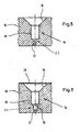
- Nozzles 14 (Figure 5 and 6) pass through upper wall 10 of chamber 7, only the nozzle exit areas 15 of which are shown in Figures 3 and 4.
- the degree of perforation of central zone 11 of wall 10 is smaller than the degree of perforation of edge zones 12 and 13.
- the degree of perforation is defined within the scope of the invention as the sum of the nozzle exit areas 15 of respective zone 11, 12, 13 in relation to the total area of this zone 11, 12, 13.
- the ratio of the degree of perforation of central zone 11 to the degree of perforation of edge zones 12 and 13 amounts in the present case to approx. 0.75 with a degree of perforation of the central zone of approx. 0.2.
- the device according to the invention produces a uniform gas cushion, whereby the smaller degree of perforation in central zone 11 ensures that the gas can discharge undisturbed via the edge zones. Since nozzles 14 are integrated into wall 10 and discharge openings or slots in wall 10 are dispensed with, no cooling shadows can be formed in glass sheets 2.
- nozzle 14 has an entry bore 22 which widens abruptly in the flow direction and which is followed by an exit hole 16.
- the entry bore has a first cylindrical section 17, the diameter of which amounts to 4 mm in the present case.
- second cylindrical section 18 with a diameter of 20 mm.
- exit hole 16 widens conically to its nozzle exit area 15 with a diameter of 60 mm.
- This nozzle design is able to slow down the gas emerging from first section 17 with a corresponding pressure build-up and to distribute it via exit hole 16, with a further pressure build-up, uniformly over the respective area of the gas cushion.
- first cylindrical section 17 of the entry bore 22 has a diameter of only 3 mm and that, between this section and second cylindrical section 18, there is provided a third cylindrical section 19 with a diameter of 10 mm, whereby short conical transition zones are provided between sections 17 and 19 and, respectively, 19 and 18.
- the smooth entry of the gas into the gas cushion is further assisted by this nozzle design.
- Figure 6 shows the arrangement of a cloth 20 made of stainless steel, which serves additionally to render the gas flow uniform and above all to adjust a uniform temperature of the whole lower face of the gas cushion.
- Chamber 7 is designed as a one-piece moulding made of ceramic. This restricts the minimum achievable diameter of first section 17 of the entry bore of nozzle 14 to approx. 3 mm. Other materials can also be used, possibly with the advantage that the diameter of first section 17 can be reduced further. Moreover, chamber 7 can be heated, in particular by electric heating elements installed close to or in wall 10 of chamber 7. This serves to achieve exact adjustment of the temperature of the gas cushion. The gas originates from a suitable source of compressed gas and is supplied already in the heated state.
Landscapes
- Chemical & Material Sciences (AREA)
- Engineering & Computer Science (AREA)
- Materials Engineering (AREA)
- Organic Chemistry (AREA)
- Re-Forming, After-Treatment, Cutting And Transporting Of Glass Products (AREA)
- Woven Fabrics (AREA)
- Laminated Bodies (AREA)
- Joining Of Glass To Other Materials (AREA)
- Devices For Use In Laboratory Experiments (AREA)
Abstract
Description
- The invention relates to a device for producing a gas cushion for supporting a preheated glass sheet, comprising a chamber connected to a source of compressed gas, the upper wall of which chamber is adapted in its external dimensions to the outline of the glass sheet and has a plurality of apertures for the passage of gas.
- The device can be used wherever it is a matter of supporting a preheated glass sheet, for example a glass sheet that is to be toughened. The main area of use, however, is the production of bent laminated glass panels, in particular for the construction of motor vehicles. A laminated window for a vehicle normally comprises two plies of glass, wherein in use one ply forms the inner surface of the window (i.e. it faces towards the vehicle interior), and the other ply forms the outer or exterior surface of the window.
- During manufacture of the window, a pair of glass sheets is heated up to the bending temperature in a preheating furnace and then conveyed to a press-bending station. Each member of the pair of sheets may be heated individually, e.g. inner and outer plies are conveyed separately through the furnace, possibly with the inner and outer plies in alternating sequence. Alternatively, the pair may be heated as a nested pair, i.e. with one ply (normally the inner ply) superposed on the other.
- The device for producing the gas cushion forms a component of the press-bending station. The respective glass sheet, or nested pair of sheets, passes from the rollers of the preheating furnace onto the gas cushion and is brought to a halt here and also centred relative to the bending mould. If rollers were also to be used here, the unavoidable dwell time would lead to the formation of markings which would considerably impair the optical properties of the glass sheet.
- The chamber comprises walls defining an internal space containing gas, and has in particular an upper wall, i.e. the wall which has an upward-facing external surface, which may be thought of as the "roof" of the chamber. The external dimensions of the upper wall of the chamber are adapted to the outline (the external dimensions) of the glass sheet, but as a rule are somewhat smaller than the external dimensions of the glass sheet to be supported, so that the glass sheet in the final position projects a few centimetres beyond the edge of the upper wall of the chamber on several, in particular on all sides, so that it can be taken up by an annular mould surrounding the chamber.
- A device of the type mentioned at the outset is known from EP 0 578 542 B1. The apertures for the passage of gas are arranged there in lines in the upper wall of the chamber, whereby there are provided between neighbouring pairs of lines slot-shaped gas discharge channels, which lead from the upper side of the chamber through the chamber to its lower side and enable an undisturbed discharge of the gas of the gas cushion.
- It has however been found that the optical properties of the glass sheets hereby achievable are capable of improvement, and the problem underlying the invention is therefore to achieve such an improvement.
- To solve this problem, the device mentioned at the outset is characterised according to the invention in that the apertures for the passage of gas are designed as nozzles, which have an entry bore as well as a progressively widening exit hole with a nozzle exit area, and that the upper wall of the chamber has a larger degree of perforation (sum of all the nozzle exit areas in relation to the total area of the respective zone) in its edge zones than in its central zone.
- The invention is based on the knowledge that the known device mentioned at the outset produces certain optical impairments of the glass sheets, which can be traced back to two phenomena which can even be locally superimposed.
- On the one hand, the edges of the slot-shaped discharge channels form so-called cooling edges, which produce cooling shadows on the glass surface. On the other hand, so-called jet marks occur in the flow impact zone of the gas jets emerging from the apertures for the passage of gas. In both cases, it leads to a non-uniform cooling rate and thus to a non-uniform heat distribution, which results in a non-uniform stress distribution.
- In order to avoid jet marks, it is known from EP 0 523 016 B1 to allow the gas jets to emerge from nozzles which have an entry bore as well as a progressively widening exit hole. These nozzles are formed by nozzle bodies which are screwed into the upper wall of the chamber and project upwards from the latter. The gas of the gas cushion is diverted downwards between the nozzle bodies and then guided away at the side. At their upper ends, the nozzle bodies thus form discharge edges, which also act as cooling edges and produce corresponding cooling shadows.
- It is also known from JP 2000247663 to optimize the gas flow by activating the gas discharge holes in a specific process.
- In contrast, neither jet marks nor cooling shadows occur according to the invention. The gas flow is slowed down during the passage through the nozzles with a corresponding pressure build-up, so that a large-area uniform gas exit can be guaranteed. Since the nozzles are integrated into the upper wall of the chamber, there is no gas deflection directed downwards at the nozzle exit, so that no discharge edges with a corresponding cooling effect are formed either. Furthermore, no entry bores from discharge channels are provided in the upper wall of the chamber. In this regard too, the creation of cooling shadows is thus eliminated.
- The discharge of the gas of the gas cushion takes place horizontally between the glass sheet and the upper wall of the chamber. Surprisingly, it has been found that it is sufficient to reduce the degree of perforation in the central zone of the upper wall of the chamber in order to guarantee an undisturbed discharge of the gas of the gas cushion. Whilst being highly effective, this measure is extremely simple. The glass sheet retains its flat, horizontal alignment, without arching up in the central zone or forming sagging zones at the edges. An adverse effect on centring on the bending tools is thus ruled out.
- Overall, the device according to the invention enables the production of bent glass sheets of the highest optical quality. This is of great importance, especially for the construction of motor vehicles. This is because here it is not only the demands on the shape tolerances of the glass sheets and their optical quality that are becoming increasingly strict, but there is also an increasing tendency to display information on the windscreen (head-up displays). The prerequisite for this is windscreens of the highest optical quality.
- To advantage, the central zone of the upper wall of the chamber, which within the scope of the invention is decisive for determining the conditions for the degree of perforation, corresponds in the magnitude of its area roughly to the sum of the edge zones.
- Particularly favourable results can be achieved when the ratio of the degree of perforation in the central zone of the upper wall of the chamber to the degree of perforation in the edge zones amounts to approx. 0.5 to 0.9, preferably approx. 0.7 - 0.8. It is understood here that the stated values are not to be understood as sharply defined limiting values, but that, in the individual case in particular, fairly large differences in the degree of perforation between the two zones may also be advisable. Tests have shown that the degree of perforation in the central zone of the upper wall of the chamber should as a rule amount to a maximum of approx. 0.3, preferably less than 0.25, in order reliably to avoid an undesirable upward arching of the glass sheet.
- Furthermore, it is advantageous for the upper wall of the chamber to have a greater degree of perforation in the edge zones of its longer sides than in the edge zones of it shorter sides. Optimum adaptation to the geometrical conditions of the glass sheet thus arises. The smaller supporting requirement in the edge zones of the shorter sides is used to promote the discharge of the gas of the gas cushion.
- The upper wall of the chamber will as a rule be designed to have rough mirror symmetry in order to simplify the design and production of the chamber. The degree of perforation to the left and right of a central axis of mirror symmetry will then be roughly in agreement. A further optimisation of the gas cushion function can however take place according to a preferred variant of the invention in that the degree of perforation diminishes from the glass-sheet feed side, which will normally be one of the short sides of the chamber, to the opposite side. Account can thus be taken of the fact that the glass sheet, when it is pushed into position over the upper wall of the chamber, pushes a gas cushion ahead of it, so that at the end of the transfer operation less and less gas has to be supplied from the chamber. As an alternative to this, a gas pressure diminishing from the feed side to the opposite side can also be provided for by a suitable adaptation of the nozzle cross-sections in the case of a degree of perforation which is symmetrical about the central mirror axis.
- Each nozzle comprises an entry bore in communication with an exit hole, which is flared, i.e. it widens in the direction of flow. A uniform gas outflow with a low speed of flow is brought about by the widening exit hole of the nozzles. This effect can however be enhanced further if the entry bore of the nozzles widens at least once abruptly in the direction of flow.
- It is particularly advantageous for the entry bore of the nozzles to have a first section with a diameter of approx. 2 to 4 mm, preferably of approx. 3 mm, as well as a second section with a diameter of approx. 20 mm, whereby the exit hole follows on from the latter. The entry bore can have a third section with a diameter of approx. 10 mm between the first and the second section. The first, second and third sections are preferably formed cylindrically and have coincident cylinder axes. The exit hole of the nozzles preferably widens conically up to the nozzle exit area with a diameter of approx. 60 mm. It goes without saying that the stated numerical values merely represent rough guidance values from which deviations are possible in both directions, without leaving the scope of the invention. The important thing is that the nozzles are designed in such a way that the gas strikes the glass surface without local pressure peaks, thereby avoiding jet marks.
- In an important development of the invention, the upper wall of the chamber is covered by a thin porous cloth made of heat-resistant material. This cloth contributes in large measure to rendering the gas flow uniform over the area of the upper wall of the chamber. The cloth also forms an area of uniform temperature, which helps to render the cooling rate, the heat distribution and the stress distribution uniform. From this viewpoint, it is particularly advantageous for the cloth to be made of heat-conductive material, preferably of corrosion-resistant steel (stainless steel).
- For the chamber, consideration can in principle be given to any sufficiently temperature-resistant material. Preferably, however, the chamber is made of ceramic material. Heating elements are preferably installed in the chamber, whereby consideration is given in particular to electric heating.
- It was stated above that the first section of the entry bores should preferably have a diameter of approx. 3 mm. This value relates to ceramic chambers, since smaller diameters cannot be drilled in ceramics. When other materials are used for the chamber, it is possible to use smaller diameters if need be, as a result of which the supporting behaviour and the temperature distribution of the gas cushion can be designed even more favourably. Overall, however, the advantages of the ceramic design predominate.
- Here, the chamber is preferably designed as a one-piece moulding.
- The invention will be explained in greater detail below with the aid of preferred examples of embodiment in connection with the appended drawings. The drawings show the following:
- Figure 1:
- in diagrammatic representation, a vertical section through a plant in which the device according to the invention is integrated;
- Figure 2:
- a plan view of the plant according to Figure 1;
- Figure 3:
- a partial plan view of a first form of embodiment of the device according to the invention;
- Figure 4:
- a partial plan view of a second form of embodiment of the device according to the invention;
- Figure 5:
- a section through a first nozzle design;
- Figure 6:
- a section through a second nozzle design.
- The plant according to Figures 1 and 2 has a preheating
furnace 1, which serves to pre-heatglass sheets 2 of a glass-sheet pair.Glass sheets 2 advance through the furnace onrollers 3, whose spacing is reduced in the area of the furnace exit, since the heated glass sheets are deformable and therefore require more intensive support.Preheating furnace 1 is followed by a bending station 4, which is provided with a glass-bendingmould 5 in the form of a ring, which conforms in outline and elevation to the desired shape of the glass sheet after bending, and a full surfacecontact vacuum mould 6. - The present invention relates especially to
gas chamber 7 for producing the gas cushion, represented diagrammatically in Figure 1.Chamber 7 has anupper wall 10, such as is shown in partial plan views in Figures 3 and 4, and is surrounded by thering mould 5. The upper wall may also, in broad terms, conform in outline and elevation to the desired shape of glass sheet to be manufactured, allowing for the fact that, as previously noted, thechamber 7 is slightly smaller than the ring mould 5 (and hence also the glass sheet) so that the chamber may pass through the ring mould. Alternatively, the upper wall of the chamber may possess a shape which is a more general approximation of the shape of the bent glass sheet, and be used for the production of bent glass sheets for several different vehicles. If only a moderate degree of bending is required, the upper wall of the chamber may be flat. - Referring to Figure 1, the
chamber 7 serves to build up a gas cushion, being supplied with compressed gas (e.g. air) by a source of compressed gas which is diagrammatically represented and designated byreference numeral 21.Glass sheets 2 transfer onto this gas cushion as soon as they leave preheatingfurnace 1.Chamber 7 then descends and placesrespective glass sheet 2 ontoring mould 5. At the same time, the vacuum mould is conveyed downwards in order to engagerespective glass sheet 2 by suction and to bring it into the desired shape. Atransport device 8, e.g. a roller conveyor (Figure 2), serves to conveybent glass sheets 2 into alehr 9. - As shown in Figure 3, the
upper wall 10 of thechamber 7 has acentral zone 11 as well asedges zones Edge zones 12 are assigned to the longer sides andedge zones 13 to the shorter sides. The area ofcentral zone 11 roughly corresponds to the sum of the areas ofedge zones central zone 11 has a course which is geometrically similar to the course of the edge ofupper wall 10 ofchamber 7. - Nozzles 14 (Figure 5 and 6) pass through
upper wall 10 ofchamber 7, only thenozzle exit areas 15 of which are shown in Figures 3 and 4. The degree of perforation ofcentral zone 11 ofwall 10 is smaller than the degree of perforation ofedge zones nozzle exit areas 15 ofrespective zone zone central zone 11 to the degree of perforation ofedge zones - The device according to the invention produces a uniform gas cushion, whereby the smaller degree of perforation in
central zone 11 ensures that the gas can discharge undisturbed via the edge zones. Sincenozzles 14 are integrated intowall 10 and discharge openings or slots inwall 10 are dispensed with, no cooling shadows can be formed inglass sheets 2. - The form of embodiment according to Figure 4 differs from that according to Figure 3 by a somewhat different shape and otherwise by the fact that here the ratio of the degree of perforation of
central zone 11 to the degree of perforation ofedge zones - Furthermore, the design of the
nozzles 14 themselves also ensures that jet marks are avoided. The first form of embodiment of the nozzle design is shown in Figure 5. According to this,nozzle 14 has an entry bore 22 which widens abruptly in the flow direction and which is followed by anexit hole 16. The entry bore has a firstcylindrical section 17, the diameter of which amounts to 4 mm in the present case. This is followed by a secondcylindrical section 18 with a diameter of 20 mm. Proceeding from this,exit hole 16 widens conically to itsnozzle exit area 15 with a diameter of 60 mm. This nozzle design is able to slow down the gas emerging fromfirst section 17 with a corresponding pressure build-up and to distribute it viaexit hole 16, with a further pressure build-up, uniformly over the respective area of the gas cushion. - The form of embodiment according to Figure 6 differs from that according to Figure 5 by the fact that first
cylindrical section 17 of the entry bore 22 has a diameter of only 3 mm and that, between this section and secondcylindrical section 18, there is provided a thirdcylindrical section 19 with a diameter of 10 mm, whereby short conical transition zones are provided betweensections - Additionally, Figure 6 shows the arrangement of a
cloth 20 made of stainless steel, which serves additionally to render the gas flow uniform and above all to adjust a uniform temperature of the whole lower face of the gas cushion. -
Chamber 7 is designed as a one-piece moulding made of ceramic. This restricts the minimum achievable diameter offirst section 17 of the entry bore ofnozzle 14 to approx. 3 mm. Other materials can also be used, possibly with the advantage that the diameter offirst section 17 can be reduced further. Moreover,chamber 7 can be heated, in particular by electric heating elements installed close to or inwall 10 ofchamber 7. This serves to achieve exact adjustment of the temperature of the gas cushion. The gas originates from a suitable source of compressed gas and is supplied already in the heated state.
Claims (15)
- A device for producing a gas cushion for supporting a preheated glass sheet (2), with a chamber (7) connected to a source (21) of compressed gas, the upper wall (10) of which chamber is adapted in its external dimensions to the outline of the glass sheet (2) and has a plurality of apertures (15) for the passage of gas,
characterised in that
the apertures are designed as nozzles (14), which have an entry bore (22) as well as a progressively widening exit hole (16), and that the upper wall (10) of the chamber (7) has a greater degree of perforation in its edge zones (12, 13) than in its central zone (11). - The device according to claim 1, characterised in that the central zone (11) of the upper wall (10) of the chamber (9) roughly corresponds in the magnitude of its area to the sum of the edge zones (12, 13).
- The device according to claim 1 or 2, characterised in that the ratio of the degree of perforation in the central zone (11) of the upper wall (10) of the chamber (7) to the degree of perforation in the edge zones (12, 13) amounts to approx. 0.5 to 0.9, preferably approx. 0.7 - 0.8.
- The device according to any one of claims 1 to 3, characterised in that the upper wall (10) of the chamber (7) has a degree of perforation of at most approx. 0.3, preferably less than 0.25, in its central zone (11).
- The device according to any one of claims 1 to 4, characterised in that the upper wall (10) of the chamber (7) has a greater degree of perforation in the edge zones (12) of its longer sides than in the edge zones (13) of its shorter sides.
- The device according to any one of claims 1 to 5, characterised in that the degree of perforation of the upper wall (10) of the chamber (7) diminishes from the feed side for the glass sheet (2) to the opposite side.
- The device according to any one of claims 1 to 6, characterised in that the entry bore (22) of at least one of the nozzles (14) widens at least once abruptly in the direction of flow.
- The device according to claim 7, characterised in that the entry bore of the nozzles (14) has a first section with a diameter of approx. 2 to 4 mm, preferably of approx. 3 mm, as well as a second section (18) with a diameter of approx. 20 mm, whereby the exit hole (16) follows on from the latter.
- The device according to claim 8, characterised in that the entry bore of the nozzles (14) has a third section (19) with a diameter of approx. 10 mm between the first and second section (17, 18).
- The device according to claim 9, characterised in that at least the first, the second and the third section (17, 18, 19) are formed cylindrically, preferably with a coinciding cylinder axis.
- The device according to any one of claims 1 to 10, characterised in that the upper wall (10) of the chamber (7) is covered by a thin porous cloth (20) made of heat-resistant material.
- The device according to claim 11, characterised in that the cloth (20) is made of heat-conductive material, preferably of corrosion-resistant steel (stainless steel).
- The device according to any one of claims 1 to 12, characterised in that the chamber (7) is made of ceramic material.
- The device according to claim 13, characterised in that the chamber (7) is designed as a one-piece moulding.
- The device according to any one of the preceding claims, characterised in that the chamber (7) is provided with heating elements.
Priority Applications (1)
| Application Number | Priority Date | Filing Date | Title |
|---|---|---|---|
| PL04722238T PL1611063T3 (en) | 2003-03-28 | 2004-03-22 | Device for producing a gas cushion |
Applications Claiming Priority (2)
| Application Number | Priority Date | Filing Date | Title |
|---|---|---|---|
| DE10314408A DE10314408A1 (en) | 2003-03-28 | 2003-03-28 | Device for generating a gas cushion |
| PCT/EP2004/002979 WO2004085325A1 (en) | 2003-03-28 | 2004-03-22 | Device for producing a gas cushion |
Publications (2)
| Publication Number | Publication Date |
|---|---|
| EP1611063A1 EP1611063A1 (en) | 2006-01-04 |
| EP1611063B1 true EP1611063B1 (en) | 2006-09-20 |
Family
ID=32946349
Family Applications (1)
| Application Number | Title | Priority Date | Filing Date |
|---|---|---|---|
| EP04722238A Expired - Lifetime EP1611063B1 (en) | 2003-03-28 | 2004-03-22 | Device for producing a gas cushion |
Country Status (13)
| Country | Link |
|---|---|
| US (1) | US7866186B2 (en) |
| EP (1) | EP1611063B1 (en) |
| JP (1) | JP4785731B2 (en) |
| KR (1) | KR101117511B1 (en) |
| CN (1) | CN100386273C (en) |
| AT (1) | ATE340150T1 (en) |
| BR (1) | BRPI0408809B1 (en) |
| CA (1) | CA2520047C (en) |
| DE (2) | DE10314408A1 (en) |
| ES (1) | ES2271869T3 (en) |
| MX (1) | MXPA05010150A (en) |
| PL (1) | PL1611063T3 (en) |
| WO (1) | WO2004085325A1 (en) |
Families Citing this family (17)
| Publication number | Priority date | Publication date | Assignee | Title |
|---|---|---|---|---|
| EP1462420A1 (en) * | 2003-03-28 | 2004-09-29 | Pilkington Plc | Apparatus and Method for Tempering Bent Glass Sheets |
| RU2393123C2 (en) * | 2005-10-24 | 2010-06-27 | Гласстек, Инк | Movement of glass sheets using hoisting jet nozzle and switching operations |
| CN101492238B (en) * | 2009-02-27 | 2011-05-18 | 桂林皮尔金顿安全玻璃有限公司 | Glass curve shaping system and use method thereof |
| CN104418498B (en) * | 2013-08-27 | 2016-12-28 | 洛阳兰迪玻璃机器股份有限公司 | Glass heating furnace |
| KR101550292B1 (en) * | 2013-11-04 | 2015-09-04 | 코닝정밀소재 주식회사 | Apparatus for forming glass substrate |
| US9573833B2 (en) | 2014-03-31 | 2017-02-21 | Corning Incorporated | Method and lift jet floatation system for shaping thin glass |
| FR3054217B1 (en) * | 2016-07-25 | 2020-02-21 | Saint-Gobain Glass France | SUCTION GLASS SUPPORT |
| PL3538498T3 (en) | 2016-11-11 | 2023-06-26 | Pilkington Group Limited | THE METHOD OF SHAPING THE GLASS SHEET AND THE GLASS SHAPING LINE USED IN THIS WAY |
| FR3059318B1 (en) * | 2016-11-30 | 2021-04-02 | Saint Gobain | THIN GLASS BOMBAGE |
| MX2019004737A (en) | 2017-01-03 | 2019-06-17 | Corning Inc | Vehicle interior systems having a curved cover glass and a display or touch panel and methods for forming the same. |
| CN111094050B (en) | 2017-07-18 | 2023-11-07 | 康宁公司 | Cold forming of complex curved glass products |
| WO2019055469A1 (en) | 2017-09-12 | 2019-03-21 | Corning Incorporated | Deadfront for displays including a touch panel on decorative glass and related methods |
| US11065960B2 (en) | 2017-09-13 | 2021-07-20 | Corning Incorporated | Curved vehicle displays |
| TWI844520B (en) | 2017-10-10 | 2024-06-11 | 美商康寧公司 | Vehicle interior systems having a curved cover glass with improved reliability and methods for forming the same |
| US11767250B2 (en) * | 2017-11-30 | 2023-09-26 | Corning Incorporated | Systems and methods for vacuum-forming aspheric mirrors |
| JP2021519740A (en) * | 2018-04-02 | 2021-08-12 | コーニング インコーポレイテッド | Equipment and methods for processing glass sheets |
| CN113276290B (en) * | 2021-06-25 | 2022-01-07 | 广东光华永盛科技有限公司 | Method for manufacturing glass |
Family Cites Families (16)
| Publication number | Priority date | Publication date | Assignee | Title |
|---|---|---|---|---|
| US3374078A (en) * | 1964-12-24 | 1968-03-19 | Pittsburgh Plate Glass Co | Apparatus for supporting and heating glass sheets on a gas bed |
| US4746348A (en) | 1986-12-29 | 1988-05-24 | Ppg Industries, Inc. | Horizontal press bending apparatus and method |
| JPH02307833A (en) | 1989-05-19 | 1990-12-21 | Nippon Sheet Glass Co Ltd | Heating of plate glass for laminated glass |
| US4952227A (en) | 1989-05-22 | 1990-08-28 | Libbey-Owens-Ford Co. | Apparatus for processing glass |
| FI84806C (en) * | 1990-03-30 | 1992-01-27 | Tamglass Oy | Bending or supporting form for glass sheets |
| BR9106493A (en) | 1990-05-22 | 1993-05-25 | Glasstech Inc | APPLIANCE TO CONFORM A HEATED GLASS SLIDE, AND, PROCESS TO CONFORM A HEATED GLASS SLIDE |
| IT1250081B (en) | 1991-07-10 | 1995-03-30 | Siv Soc Italiana Vetro | EQUIPMENT AND PROCEDURE FOR THE MANUFACTURE OF COMPLEX SHAPED GLASS |
| IT1250082B (en) | 1991-07-10 | 1995-03-30 | Siv Soc Italiana Vetro | APPARATUS AND PROCEDURE FOR THE MANUFACTURE OF GLASSES WITH A COMPLEX SHAPE SUITABLE FOR USE ON VEHICLES |
| FR2693452B1 (en) * | 1992-07-09 | 1994-09-02 | Saint Gobain Vitrage Int | Method and device for supporting and transferring glass sheets in a forming cell. |
| US5857358A (en) | 1996-10-23 | 1999-01-12 | Donnelly Corporation | Method and apparatus for bending glass |
| US5938810A (en) | 1996-10-23 | 1999-08-17 | Donnelly Corporation | Apparatus for tempering and bending glass |
| US5833729A (en) | 1996-12-16 | 1998-11-10 | Ppg Industries, Inc. | Method and apparatus for bending glass sheets |
| JP2000247663A (en) | 1999-03-02 | 2000-09-12 | Nippon Sheet Glass Co Ltd | Bed structure for floating sheet glass |
| JP2001158631A (en) | 1999-11-30 | 2001-06-12 | Central Glass Co Ltd | Method for curving and molding glass plate |
| US7240519B2 (en) * | 2002-11-18 | 2007-07-10 | Ppg Industries Ohio, Inc. | Apparatus and method for bending glass sheets |
| US7866187B2 (en) | 2003-09-24 | 2011-01-11 | Pilkington North America, Inc. | Press bending station for the bending of glass sheets |
-
2003
- 2003-03-28 DE DE10314408A patent/DE10314408A1/en not_active Withdrawn
-
2004
- 2004-03-22 AT AT04722238T patent/ATE340150T1/en not_active IP Right Cessation
- 2004-03-22 BR BRPI0408809-3A patent/BRPI0408809B1/en not_active IP Right Cessation
- 2004-03-22 US US10/551,286 patent/US7866186B2/en not_active Expired - Lifetime
- 2004-03-22 EP EP04722238A patent/EP1611063B1/en not_active Expired - Lifetime
- 2004-03-22 MX MXPA05010150A patent/MXPA05010150A/en active IP Right Grant
- 2004-03-22 PL PL04722238T patent/PL1611063T3/en unknown
- 2004-03-22 JP JP2006504784A patent/JP4785731B2/en not_active Expired - Lifetime
- 2004-03-22 CA CA2520047A patent/CA2520047C/en not_active Expired - Lifetime
- 2004-03-22 ES ES04722238T patent/ES2271869T3/en not_active Expired - Lifetime
- 2004-03-22 WO PCT/EP2004/002979 patent/WO2004085325A1/en not_active Ceased
- 2004-03-22 DE DE602004002472T patent/DE602004002472T2/en not_active Expired - Lifetime
- 2004-03-22 CN CNB2004800085822A patent/CN100386273C/en not_active Expired - Lifetime
- 2004-03-22 KR KR1020057018303A patent/KR101117511B1/en not_active Expired - Lifetime
Also Published As
| Publication number | Publication date |
|---|---|
| ES2271869T3 (en) | 2007-04-16 |
| ATE340150T1 (en) | 2006-10-15 |
| DE602004002472D1 (en) | 2006-11-02 |
| WO2004085325A1 (en) | 2004-10-07 |
| DE10314408A1 (en) | 2004-10-07 |
| DE602004002472T2 (en) | 2007-02-22 |
| MXPA05010150A (en) | 2006-03-17 |
| US20060277947A1 (en) | 2006-12-14 |
| JP4785731B2 (en) | 2011-10-05 |
| JP2006521269A (en) | 2006-09-21 |
| PL1611063T3 (en) | 2007-02-28 |
| EP1611063A1 (en) | 2006-01-04 |
| CN100386273C (en) | 2008-05-07 |
| BRPI0408809A (en) | 2006-03-28 |
| BRPI0408809B1 (en) | 2013-01-22 |
| CA2520047C (en) | 2012-09-11 |
| CN1771203A (en) | 2006-05-10 |
| KR101117511B1 (en) | 2012-03-16 |
| CA2520047A1 (en) | 2004-10-07 |
| KR20050121227A (en) | 2005-12-26 |
| US7866186B2 (en) | 2011-01-11 |
Similar Documents
| Publication | Publication Date | Title |
|---|---|---|
| CA2520047C (en) | Device for producing a gas cushion | |
| EP3126300B1 (en) | Method and lift jet floatation system for shaping thin glass | |
| JP3801665B2 (en) | Method and apparatus for bend-tempering glass plate | |
| US5755845A (en) | Method and apparatus for bending and tempering glass sheets | |
| KR20060106829A (en) | Method and apparatus for cutting sheet glass | |
| US11420895B2 (en) | Apparatus and method for processing a glass substrate | |
| EP1559690A1 (en) | Method and device for producing curved reinforced glass plate | |
| US6751988B2 (en) | Process for bend-shaping a glass plate and an apparatus for bend-shaping the glass plate | |
| KR100616780B1 (en) | Apparatus for cooling a curved glass sheet, a method of using the apparatus and a laminated glazing assembly composed of the sheet | |
| EP1615855B1 (en) | Process and plant for the treatment of the glass sheets of an asymmetric glass-sheet pair | |
| EP1608597B1 (en) | Tempering bent glass sheets | |
| US6032489A (en) | Method for manufacturing tempered glass sheet and apparatus for manufacturing the same | |
| WO1993001140A1 (en) | Method and equipment for bending and/or tempering glass sheets | |
| US20210147277A1 (en) | Method and device for bending sheets | |
| EP0989101A2 (en) | Apparatus for producing bent glass sheets | |
| JP4583363B2 (en) | Method and apparatus for forming composite bent glass sheet |
Legal Events
| Date | Code | Title | Description |
|---|---|---|---|
| PUAI | Public reference made under article 153(3) epc to a published international application that has entered the european phase |
Free format text: ORIGINAL CODE: 0009012 |
|
| 17P | Request for examination filed |
Effective date: 20051028 |
|
| AK | Designated contracting states |
Kind code of ref document: A1 Designated state(s): AT BE BG CH CY CZ DE DK EE ES FI FR GB GR HU IE IT LI LU MC NL PL PT RO SE SI SK TR |
|
| AX | Request for extension of the european patent |
Extension state: AL LT LV MK |
|
| GRAP | Despatch of communication of intention to grant a patent |
Free format text: ORIGINAL CODE: EPIDOSNIGR1 |
|
| DAX | Request for extension of the european patent (deleted) | ||
| GRAS | Grant fee paid |
Free format text: ORIGINAL CODE: EPIDOSNIGR3 |
|
| GRAA | (expected) grant |
Free format text: ORIGINAL CODE: 0009210 |
|
| AK | Designated contracting states |
Kind code of ref document: B1 Designated state(s): AT BE BG CH CY CZ DE DK EE ES FI FR GB GR HU IE IT LI LU MC NL PL PT RO SE SI SK TR |
|
| PG25 | Lapsed in a contracting state [announced via postgrant information from national office to epo] |
Ref country code: SK Free format text: LAPSE BECAUSE OF FAILURE TO SUBMIT A TRANSLATION OF THE DESCRIPTION OR TO PAY THE FEE WITHIN THE PRESCRIBED TIME-LIMIT Effective date: 20060920 Ref country code: SI Free format text: LAPSE BECAUSE OF FAILURE TO SUBMIT A TRANSLATION OF THE DESCRIPTION OR TO PAY THE FEE WITHIN THE PRESCRIBED TIME-LIMIT Effective date: 20060920 Ref country code: RO Free format text: LAPSE BECAUSE OF FAILURE TO SUBMIT A TRANSLATION OF THE DESCRIPTION OR TO PAY THE FEE WITHIN THE PRESCRIBED TIME-LIMIT Effective date: 20060920 Ref country code: CH Free format text: LAPSE BECAUSE OF FAILURE TO SUBMIT A TRANSLATION OF THE DESCRIPTION OR TO PAY THE FEE WITHIN THE PRESCRIBED TIME-LIMIT Effective date: 20060920 Ref country code: LI Free format text: LAPSE BECAUSE OF FAILURE TO SUBMIT A TRANSLATION OF THE DESCRIPTION OR TO PAY THE FEE WITHIN THE PRESCRIBED TIME-LIMIT Effective date: 20060920 Ref country code: NL Free format text: LAPSE BECAUSE OF FAILURE TO SUBMIT A TRANSLATION OF THE DESCRIPTION OR TO PAY THE FEE WITHIN THE PRESCRIBED TIME-LIMIT Effective date: 20060920 Ref country code: AT Free format text: LAPSE BECAUSE OF FAILURE TO SUBMIT A TRANSLATION OF THE DESCRIPTION OR TO PAY THE FEE WITHIN THE PRESCRIBED TIME-LIMIT Effective date: 20060920 Ref country code: FI Free format text: LAPSE BECAUSE OF FAILURE TO SUBMIT A TRANSLATION OF THE DESCRIPTION OR TO PAY THE FEE WITHIN THE PRESCRIBED TIME-LIMIT Effective date: 20060920 Ref country code: IT Free format text: LAPSE BECAUSE OF FAILURE TO SUBMIT A TRANSLATION OF THE DESCRIPTION OR TO PAY THE FEE WITHIN THE PRESCRIBED TIME-LIMIT;WARNING: LAPSES OF ITALIAN PATENTS WITH EFFECTIVE DATE BEFORE 2007 MAY HAVE OCCURRED AT ANY TIME BEFORE 2007. THE CORRECT EFFECTIVE DATE MAY BE DIFFERENT FROM THE ONE RECORDED. Effective date: 20060920 |
|
| REG | Reference to a national code |
Ref country code: GB Ref legal event code: FG4D |
|
| REG | Reference to a national code |
Ref country code: CH Ref legal event code: EP |
|
| REG | Reference to a national code |
Ref country code: IE Ref legal event code: FG4D |
|
| REF | Corresponds to: |
Ref document number: 602004002472 Country of ref document: DE Date of ref document: 20061102 Kind code of ref document: P |
|
| REG | Reference to a national code |
Ref country code: DE Ref legal event code: R096 Ref document number: 602004002472 Country of ref document: DE Effective date: 20061102 |
|
| PG25 | Lapsed in a contracting state [announced via postgrant information from national office to epo] |
Ref country code: BG Free format text: LAPSE BECAUSE OF FAILURE TO SUBMIT A TRANSLATION OF THE DESCRIPTION OR TO PAY THE FEE WITHIN THE PRESCRIBED TIME-LIMIT Effective date: 20061220 Ref country code: DK Free format text: LAPSE BECAUSE OF FAILURE TO SUBMIT A TRANSLATION OF THE DESCRIPTION OR TO PAY THE FEE WITHIN THE PRESCRIBED TIME-LIMIT Effective date: 20061220 Ref country code: SE Free format text: LAPSE BECAUSE OF FAILURE TO SUBMIT A TRANSLATION OF THE DESCRIPTION OR TO PAY THE FEE WITHIN THE PRESCRIBED TIME-LIMIT Effective date: 20061220 |
|
| REG | Reference to a national code |
Ref country code: HU Ref legal event code: AG4A Ref document number: E001060 Country of ref document: HU Ref country code: PL Ref legal event code: T3 |
|
| NLV1 | Nl: lapsed or annulled due to failure to fulfill the requirements of art. 29p and 29m of the patents act | ||
| PG25 | Lapsed in a contracting state [announced via postgrant information from national office to epo] |
Ref country code: PT Free format text: LAPSE BECAUSE OF FAILURE TO SUBMIT A TRANSLATION OF THE DESCRIPTION OR TO PAY THE FEE WITHIN THE PRESCRIBED TIME-LIMIT Effective date: 20070312 |
|
| REG | Reference to a national code |
Ref country code: CH Ref legal event code: PL |
|
| ET | Fr: translation filed | ||
| REG | Reference to a national code |
Ref country code: ES Ref legal event code: FG2A Ref document number: 2271869 Country of ref document: ES Kind code of ref document: T3 |
|
| PLBE | No opposition filed within time limit |
Free format text: ORIGINAL CODE: 0009261 |
|
| STAA | Information on the status of an ep patent application or granted ep patent |
Free format text: STATUS: NO OPPOSITION FILED WITHIN TIME LIMIT |
|
| 26N | No opposition filed |
Effective date: 20070621 |
|
| REG | Reference to a national code |
Ref country code: DE Ref legal event code: R097 Ref document number: 602004002472 Country of ref document: DE Effective date: 20070621 |
|
| PG25 | Lapsed in a contracting state [announced via postgrant information from national office to epo] |
Ref country code: IE Free format text: LAPSE BECAUSE OF NON-PAYMENT OF DUE FEES Effective date: 20070322 Ref country code: MC Free format text: LAPSE BECAUSE OF NON-PAYMENT OF DUE FEES Effective date: 20070331 |
|
| PG25 | Lapsed in a contracting state [announced via postgrant information from national office to epo] |
Ref country code: GR Free format text: LAPSE BECAUSE OF FAILURE TO SUBMIT A TRANSLATION OF THE DESCRIPTION OR TO PAY THE FEE WITHIN THE PRESCRIBED TIME-LIMIT Effective date: 20061221 |
|
| PG25 | Lapsed in a contracting state [announced via postgrant information from national office to epo] |
Ref country code: EE Free format text: LAPSE BECAUSE OF FAILURE TO SUBMIT A TRANSLATION OF THE DESCRIPTION OR TO PAY THE FEE WITHIN THE PRESCRIBED TIME-LIMIT Effective date: 20060920 |
|
| PG25 | Lapsed in a contracting state [announced via postgrant information from national office to epo] |
Ref country code: CY Free format text: LAPSE BECAUSE OF FAILURE TO SUBMIT A TRANSLATION OF THE DESCRIPTION OR TO PAY THE FEE WITHIN THE PRESCRIBED TIME-LIMIT Effective date: 20060920 |
|
| PGFP | Annual fee paid to national office [announced via postgrant information from national office to epo] |
Ref country code: GB Payment date: 20130320 Year of fee payment: 10 |
|
| GBPC | Gb: european patent ceased through non-payment of renewal fee |
Effective date: 20140322 |
|
| PG25 | Lapsed in a contracting state [announced via postgrant information from national office to epo] |
Ref country code: GB Free format text: LAPSE BECAUSE OF NON-PAYMENT OF DUE FEES Effective date: 20140322 |
|
| REG | Reference to a national code |
Ref country code: FR Ref legal event code: PLFP Year of fee payment: 13 |
|
| REG | Reference to a national code |
Ref country code: FR Ref legal event code: PLFP Year of fee payment: 14 |
|
| REG | Reference to a national code |
Ref country code: FR Ref legal event code: PLFP Year of fee payment: 15 |
|
| PGFP | Annual fee paid to national office [announced via postgrant information from national office to epo] |
Ref country code: LU Payment date: 20230320 Year of fee payment: 20 Ref country code: FR Payment date: 20230320 Year of fee payment: 20 Ref country code: CZ Payment date: 20230310 Year of fee payment: 20 |
|
| PGFP | Annual fee paid to national office [announced via postgrant information from national office to epo] |
Ref country code: TR Payment date: 20230320 Year of fee payment: 20 Ref country code: PL Payment date: 20230310 Year of fee payment: 20 Ref country code: HU Payment date: 20230322 Year of fee payment: 20 Ref country code: DE Payment date: 20230320 Year of fee payment: 20 Ref country code: BE Payment date: 20230321 Year of fee payment: 20 |
|
| P01 | Opt-out of the competence of the unified patent court (upc) registered |
Effective date: 20230514 |
|
| PGFP | Annual fee paid to national office [announced via postgrant information from national office to epo] |
Ref country code: IT Payment date: 20230331 Year of fee payment: 20 Ref country code: ES Payment date: 20230414 Year of fee payment: 20 |
|
| REG | Reference to a national code |
Ref country code: DE Ref legal event code: R071 Ref document number: 602004002472 Country of ref document: DE |
|
| REG | Reference to a national code |
Ref country code: ES Ref legal event code: FD2A Effective date: 20240402 |
|
| REG | Reference to a national code |
Ref country code: BE Ref legal event code: MK Effective date: 20240322 |
|
| PG25 | Lapsed in a contracting state [announced via postgrant information from national office to epo] |
Ref country code: ES Free format text: LAPSE BECAUSE OF EXPIRATION OF PROTECTION Effective date: 20240323 |
|
| PG25 | Lapsed in a contracting state [announced via postgrant information from national office to epo] |
Ref country code: ES Free format text: LAPSE BECAUSE OF EXPIRATION OF PROTECTION Effective date: 20240323 Ref country code: CZ Free format text: LAPSE BECAUSE OF EXPIRATION OF PROTECTION Effective date: 20240322 |