EP1610680B1 - Air circulation apparatus and methods for plethysmographic measurement chambers - Google Patents
Air circulation apparatus and methods for plethysmographic measurement chambers Download PDFInfo
- Publication number
- EP1610680B1 EP1610680B1 EP04758369.5A EP04758369A EP1610680B1 EP 1610680 B1 EP1610680 B1 EP 1610680B1 EP 04758369 A EP04758369 A EP 04758369A EP 1610680 B1 EP1610680 B1 EP 1610680B1
- Authority
- EP
- European Patent Office
- Prior art keywords
- chamber
- air
- measurement
- coupled
- measurement chamber
- Prior art date
- Legal status (The legal status is an assumption and is not a legal conclusion. Google has not performed a legal analysis and makes no representation as to the accuracy of the status listed.)
- Expired - Lifetime
Links
- 238000005259 measurement Methods 0.000 title claims description 124
- 238000000034 method Methods 0.000 title claims description 32
- 239000000203 mixture Substances 0.000 claims description 22
- 238000012360 testing method Methods 0.000 claims description 11
- 238000012544 monitoring process Methods 0.000 claims description 9
- 230000010355 oscillation Effects 0.000 claims description 6
- 238000005086 pumping Methods 0.000 claims description 6
- 230000004044 response Effects 0.000 claims description 4
- 230000002572 peristaltic effect Effects 0.000 claims description 2
- 238000010438 heat treatment Methods 0.000 claims 2
- 238000007789 sealing Methods 0.000 claims 1
- 239000003570 air Substances 0.000 description 72
- XLYOFNOQVPJJNP-UHFFFAOYSA-N water Substances O XLYOFNOQVPJJNP-UHFFFAOYSA-N 0.000 description 9
- 238000009825 accumulation Methods 0.000 description 5
- 230000005534 acoustic noise Effects 0.000 description 5
- 239000012080 ambient air Substances 0.000 description 4
- 238000006073 displacement reaction Methods 0.000 description 4
- 230000008878 coupling Effects 0.000 description 3
- 238000010168 coupling process Methods 0.000 description 3
- 238000005859 coupling reaction Methods 0.000 description 3
- 230000036541 health Effects 0.000 description 3
- 238000005303 weighing Methods 0.000 description 3
- 230000002411 adverse Effects 0.000 description 2
- 230000000694 effects Effects 0.000 description 2
- 235000013861 fat-free Nutrition 0.000 description 2
- 230000005484 gravity Effects 0.000 description 2
- 238000012986 modification Methods 0.000 description 2
- 230000004048 modification Effects 0.000 description 2
- 230000000737 periodic effect Effects 0.000 description 2
- 230000029058 respiratory gaseous exchange Effects 0.000 description 2
- 238000012549 training Methods 0.000 description 2
- 208000019901 Anxiety disease Diseases 0.000 description 1
- 208000024172 Cardiovascular disease Diseases 0.000 description 1
- 241000238558 Eucarida Species 0.000 description 1
- 208000031226 Hyperlipidaemia Diseases 0.000 description 1
- 206010020772 Hypertension Diseases 0.000 description 1
- 208000023178 Musculoskeletal disease Diseases 0.000 description 1
- 210000000577 adipose tissue Anatomy 0.000 description 1
- 230000036506 anxiety Effects 0.000 description 1
- 230000008901 benefit Effects 0.000 description 1
- 230000005540 biological transmission Effects 0.000 description 1
- 230000006835 compression Effects 0.000 description 1
- 238000007906 compression Methods 0.000 description 1
- 238000011109 contamination Methods 0.000 description 1
- 238000011161 development Methods 0.000 description 1
- 206010012601 diabetes mellitus Diseases 0.000 description 1
- 238000010790 dilution Methods 0.000 description 1
- 239000012895 dilution Substances 0.000 description 1
- 201000010099 disease Diseases 0.000 description 1
- 208000037265 diseases, disorders, signs and symptoms Diseases 0.000 description 1
- 230000005611 electricity Effects 0.000 description 1
- 238000011156 evaluation Methods 0.000 description 1
- 210000003722 extracellular fluid Anatomy 0.000 description 1
- 230000036571 hydration Effects 0.000 description 1
- 238000006703 hydration reaction Methods 0.000 description 1
- 230000002706 hydrostatic effect Effects 0.000 description 1
- 238000002847 impedance measurement Methods 0.000 description 1
- 230000003834 intracellular effect Effects 0.000 description 1
- 210000002977 intracellular fluid Anatomy 0.000 description 1
- 208000017169 kidney disease Diseases 0.000 description 1
- 208000018773 low birth weight Diseases 0.000 description 1
- 231100000533 low birth weight Toxicity 0.000 description 1
- 210000004072 lung Anatomy 0.000 description 1
- 230000007246 mechanism Effects 0.000 description 1
- 230000002503 metabolic effect Effects 0.000 description 1
- 210000003205 muscle Anatomy 0.000 description 1
- 238000000059 patterning Methods 0.000 description 1
- 230000000704 physical effect Effects 0.000 description 1
- 230000003334 potential effect Effects 0.000 description 1
- 230000008569 process Effects 0.000 description 1
- 230000009291 secondary effect Effects 0.000 description 1
Images

Classifications
-
- A—HUMAN NECESSITIES
- A61—MEDICAL OR VETERINARY SCIENCE; HYGIENE
- A61B—DIAGNOSIS; SURGERY; IDENTIFICATION
- A61B5/00—Measuring for diagnostic purposes; Identification of persons
- A61B5/103—Measuring devices for testing the shape, pattern, colour, size or movement of the body or parts thereof, for diagnostic purposes
- A61B5/107—Measuring physical dimensions, e.g. size of the entire body or parts thereof
- A61B5/1073—Measuring volume, e.g. of limbs
-
- G—PHYSICS
- G01—MEASURING; TESTING
- G01F—MEASURING VOLUME, VOLUME FLOW, MASS FLOW OR LIQUID LEVEL; METERING BY VOLUME
- G01F17/00—Methods or apparatus for determining the capacity of containers or cavities, or the volume of solid bodies
-
- A—HUMAN NECESSITIES
- A61—MEDICAL OR VETERINARY SCIENCE; HYGIENE
- A61B—DIAGNOSIS; SURGERY; IDENTIFICATION
- A61B5/00—Measuring for diagnostic purposes; Identification of persons
- A61B5/08—Measuring devices for evaluating the respiratory organs
- A61B5/0806—Measuring devices for evaluating the respiratory organs by whole-body plethysmography
Definitions
- This invention relates generally to apparatus and methods for providing accurate measurement of human body composition using a plethysmographic measurement chamber. More specifically, the present inventions relate to apparatus and methods for plethysmographic measurement of human subjects in which air within a plethysmographic measurement chamber is circulated and renewed with air from outside the chamber.
- body composition including measurement of fat and fat-free mass
- body composition provides physicians with important information regarding physical status.
- Excess body fat has been associated with a variety of disease processes, such as cardiovascular disease, diabetes, hypertension, hyperlipidemia, kidney disease, and musculoskeletal disorders.
- Low levels of fat free mass have been found to be critically adverse to the health of certain at-risk populations, such as infants, the obese, and the elderly.
- body composition has been shown to be useful as a diagnostic measurement for the assessment of physical status. Disturbances in health and growth, regardless of origin, almost always affect body composition in newborns and infants. For example, for very low birth weight infants, body composition and variation in body composition are relevant both in determining infant energy needs and in evaluation of health progression and physical development.
- a variety of methods are currently used in the assessment of body composition.
- One common method is a skin fold measurement, typically performed using calipers that compress the skin at certain points on the body. While non-invasive, this method suffers from poor accuracy on account of variations in fat patterning, misapplication of population specific prediction equations, improper site identification for compressing the skin, poor fold grasping, and the necessity for significant technician training to administer the test properly.
- Bioelectric impedance analysis Another method employed is bioelectric impedance analysis ("BIA").
- Bioelectric impedance measurements rely on the fact that the body contains intracellular and extracellular fluids that conduct electricity.
- BIA involves passing a high frequency electric current through the subject's body, determining the subjects' measured impedance value, and calculating body composition based on the subject's measured impedance and known impedance values for human muscle tissue.
- this method can be greatly affected by the state of hydration of the subject, and variations in temperature of both the subject and the surrounding environment.
- BIA has not been successfully applied with infant subjects.
- hydrostatic weighing The most common method used when precision body composition measurements are required is hydrostatic weighing. This method is based upon the application of Archimedes principle, and requires weighing the subject on land, repeated weighing under water, and an estimation of air present in the lungs of the subject using gas dilution techniques.
- hydrodensitometry is time consuming, typically unpleasant for the subjects, requires both significant subject participation and considerable technician training and, due to the necessary facilities for implementation, is unsuitable for clinical practice. Further, the application of hydrodensitometry to infant, elderly, and disabled populations is precluded by the above concerns.
- Air displacement plethysmography determines the volume of a subject to be measured by measuring the volume of air displaced by the subject in an enclosed chamber. Volume of air in the chamber is calculated through application of Boyle's Law and/or Poisson's Law to conditions within the chamber. More particularly, in the most prevalent method of air displacement plethysmography used for measuring human body composition (such as disclosed in U.S. Patent No. 4,369,652, issued to Gundlach , and U.S. Patent No. 5,105,825, issued to Dempster ), volume perturbations of a fixed frequency of oscillation are induced within a measurement chamber, which perturbations lead to pressure fluctuations within the chamber.
- the amplitude of the pressure fluctuations is determined, and used to calculate the volume of air within the chamber using Boyle's Law (defining the relationship of pressure and volume under isothermal conditions) or Poisson's law (defining the relationship of pressure and volume under adiabatic conditions). Body volume is then calculated indirectly by subtracting the volume of air remaining inside the chamber when the subject is inside from the volume of air in the chamber when it is empty.
- body composition can be calculated based on the measured subject volume, weight of the subject, and subject surface area (which, for human subjects, is a function of subject weight and subject height), using known formulas defining the relationship between density and human fat mass.
- plethysmographic systems require very accurate measurements of volume to yield valid body composition results.
- plethysmographic measurement of infant body composition requires even more accurate measurement of volume given the higher metabolic activity of infant subjects as a proportion of body size, and the longer measurement periods required for infants on account of larger breathing artifacts. Due to this required accuracy of volume measurement, current plethysmographic measurement systems, while effective at measuring the volume of inanimate objects, have suffered from secondary effects that limit the accuracy of those systems with human subjects. For example, accumulation of water vapor and CO 2 in the measurement chamber can significantly affect results on account of the differing adiabatic compression properties of triatomic gasses (such as CO 2 and H 2 O) and diatomic gasses (such as O 2 and N 2 ). Similarly, variations in chamber temperature due to body heat produced by a test subject may also affect the accuracy of volume measurement.
- composition of air within the measurement chamber has an effect on the comfort and safety of the test subject. Specifically, accumulation of CO 2 beyond certain levels may adversely affect the infant subject. Thus, current plethysmographic systems that do not account for accumulation of triatomic gasses tend to be less suitable for determining infant body composition.
- US 3 769 834 A relates to a system for measuring the volume and volume variations of the human body under zero gravity conditions.
- An enclosed chamber having a defined volume and arranged for receiving a human body is provided with means for infrasonically varying the volume of the chamber.
- a snorkel breathing device is used that allows a person to breathe in the closed chamber.
- the changes in volume produce resultant changes in pressure, and under substantially isentropic conditions, an isentropic relationship permits a determination of gas volume which, in turn, when related to total chamber volume permits a determination of the body volume.
- volume changes of a human independent of gravity conditions can be determined.
- the present invention generally consists of a plethysmographic measurement system that includes an air circulation system.
- the air circulation system comprises a pump assembly of one or more pumps coupled to the measurement chamber via one or more inlet tubes and one or more exhaust tubes.
- the lengths of the inlet tube(s) and exhaust tube(s) are selected such that the acoustic properties of the measurement chamber are not affected by the air circulation system.
- the source of air for the air circulation system is a controlled temperature environment, such that chamber temperature can be maintained relatively constant in spite of body heat produced by the test subject.
- the inlet tube and exhaust tube further comprise multiple parallel tubes to provide for quieter, laminar flow within the tubes.
- a single inlet tube and a single exhaust tube are coupled between the pump assembly and an inlet manifold and exhaust manifold, respectively.
- the inlet manifold and exhaust manifold are then coupled to the chamber via multiple parallel tubes, providing for less flow resistance than full lengths of multiple parallel tubes, while still attenuating noise generated by turbulent flow.
- Plethysmographic system 20 is composed of plethysmographic measurement chamber 22, chamber door assembly 24, plethysmographic measurement components 26 (including volume perturbation element 28, and air circulation component chamber 30.
- Air circulation component chamber 30 houses air circulation components 31, which provide the mechanism for air circulation within chamber 22.
- Plethysmographic measurement components 26 are coupled to computer 32, which includes software 34 for controlling the operation of plethysmographic measurement components 26.
- Air circulation component chamber 30 is coupled to measurement chamber 22 via inlet tube 36 and exhaust tube 38.
- Inlet tube 36 and exhaust tube 38 allow for air to be continuously circulated and renewed within measurement chamber 22 through the operation of air circulation components 31.
- inlet tube 36 and exhaust tube 38 could comprise multiple parallel tubes in accordance with the present invention. Such an arrangement would result in quieter, laminar flow within the tubes, thereby generating less acoustic noise, at the expense of increased flow resistance.
- Plethysmographic system 50 is composed of plethysmographic measurement chamber 52 , chamber door 54, plethysmographic measurement components 56 (including volume perturbation element 58 ), and air circulation component chamber 60, which houses air circulation components 62.
- Plethysmographic measurement components 56 are coupled to computer 64, which includes software 66 for controlling the operation of plethysmographic measurement components 56.
- Air circulation component chamber 60 is coupled to measurement chamber 52 via inlet tube 68 and exhaust tube 70.
- Inlet tube 68 and exhaust tube 70 allow for air to be continuously renewed and circulated within measurement chamber 52 by air circulation components 62.
- inlet tube 68 and exhaust tube 70 could comprise multiple parallel tubes in accordance with the present invention.
- air circulation component chamber 60 could alternatively be housed within measurement chamber 52, so long as air circulation components 62 had access to ambient air outside of measurement chamber 52.
- Pump assembly 80 (shown housed within air circulation component chamber 82 ) is coupled to measurement chamber 84 via inlet tube 86 and exhaust tube 88. Pump assembly 80 both pumps ambient air through inlet tube 86 into measurement chamber 84, and pumps air contaminated with triatomic gasses (such as water vapor and CO 2 ) out of measurement chamber 84 through exhaust tube 88. Thus, air is continuously circulated and renewed within measurement chamber 84, preventing buildup of triatomic gasses that could affect the accuracy of plethysmographic measurement.
- triatomic gasses such as water vapor and CO 2
- pump assembly 80 is housed within air circulation component chamber 82, one of ordinary skill in the art would recognize that pump assembly 80 could be physically located anywhere in relation to measurement chamber 84, so long as pump assembly 80 provided for circulation and renewal of air within chamber 84.
- Pump assembly 80 is further comprised of one or more pumps for pumping air into and out of measurement chamber 84.
- pump assembly 80 further comprises inlet 89, inlet pump 90, exhaust 91 and exhaust pump 92.
- Inlet pump 90 pumps ambient air from inlet 89 through inlet tube 86 into measurement chamber 84, and exhaust pump 92 pumps contaminated air out of measurement chamber 84 through exhaust tube 88 and out exhaust 91.
- Inlet pump 90 and exhaust pump 92 are preferably turbine or centrifugal pumps.
- other types of pumps suitable for pumping gasses including fan pumps, diaphragm pumps, peristaltic pumps, and piston pumps.
- inlet pump 90 and exhaust pump 92 are placed at the ends of inlet tube 86 and exhaust tube 88 distal from measurement chamber 84, respectively. This placement allows for maximum attenuation of noise generated by inlet pump 90 and exhaust pump 92.
- inlet pump 90 and exhaust pump 92 may be placed at any point in the airflow between measurement chamber 84 and atmosphere in accordance with the present invention.
- pump assembly 80 could also be comprised of a single pump, as opposed to a combination of input and exhaust pumps. While such a pump assembly would result in chamber pressure somewhat different from ambient, this may well be acceptable in some plethysmographic measurement systems.
- inlet pump 90 and exhaust pump 92 do not have to be placed within a single pump assembly.
- inlet pump 90 and exhaust pump 92 could be mounted separately within air circulation component chamber 82 .
- one or both of inlet pump 90 and exhaust pump 92 could be mounted outside of air circulation component chamber 82.
- inlet 89 and exhaust 91 be kept separate from one another. Such a placement of inlet 89 and exhaust 91 ensures that contaminated air pumped out of measurement chamber 84 is exhausted away from inlet 89, in order to prevent contamination of incoming air by excess CO 2 and water vapor being discharged from exhaust 91.
- inlet tube 86 and exhaust tube 88 are important to maintain the acoustic properties of measurement chamber 84, such that accurate measurement of chamber volume can be attained in spite of the coupling of measurement chamber 84 to the external environment. More particularly, by coupling measurement chamber 84 to the environment, acoustic noise could pass through inlet tube 86 and exhaust tube 88 into measurement chamber 84, thereby affecting the accuracy of the body composition measurement. Further, acoustic energy at the frequency of perturbation could also leak outside measurement chamber 84, again affecting the accuracy of measurement.
- inlet tube 86 and exhaust tube 88 possesses inertia, which acts to resist movement of air within the tubes in response to pressure fluctuations (such as acoustic noise from outside measurement chamber 84, or the periodic perturbations generated during plethysmographic measurement). This property can be maximized through selection of the length of inlet tube 86 and exhaust tube 88.
- measurement chamber 84 and inlet tube 86 can be modeled in a combined manner as a Helmholtz resonator.
- the Helmholtz resonator realized by the combination of measurement chamber 84 and inlet tube 86 /exhaust tube 88 acts as a low-pass filter, attenuating acoustic noise above the resonant frequency of the system (which is inversely proportional to the square root of the length of the tube).
- the length of inlet tube 86 and exhaust tube 88 can be selected such that the acoustic low-pass filter properties of the chamber/tube system attenuate frequencies at or above the perturbation frequency.
- the lengths of the inlet tubes and exhaust tubes were selected such that the resonant frequency of the chamber/tube system was an order of magnitude below the perturbation frequency.
- the acoustic properties of inlet tube 86 and exhaust tube 88 can be looked at independently from measurement chamber 84.
- the length of the tube would preferably be set at one-quarter the wavelength corresponding to the perturbation frequency in order to minimize transmission of pressure fluctuations through inlet tube 86 and exhaust tube 88 at the perturbation frequency. While adopting this model has been found to yield some benefit, in practice it has been found that simply ensuring that inlet tube 86 and exhaust tube 88 are of sufficient length to attenuate periodic signals at or above the frequency of perturbation (typically, between 3 Hz and 20 Hz, depending on the type of plethysmographic measurement system used) produces satisfactory results.
- air circulation component chamber 82 further includes heater element 98, temperature monitoring circuitry 100, and controlled temperature inlet 102.
- temperature monitoring circuitry 100 monitors the temperature of controlled temperature inlet 102, and varies the operation of heater element 98 to maintain a constant temperature within controlled temperature inlet 102.
- Controlled temperature inlet 102 acts as the source of air for inlet pump 90; thus, air is pumped from temperature controlled inlet 102 through inlet tube 86 into measurement chamber 84 by means of inlet pump 90.
- heater element 98 can be used to heat the air within inlet tube 86 via conduction.
- inlet pump 90 draws air through inlet 89 from the environment outside air circulation component chamber 82.
- Temperature monitoring circuitry 100 monitors the temperature of air within inlet tube 86, and varies the operation of heater element 98 to maintain a constant temperature of incoming air within inlet tube 86 .
- heater element 98 could be coupled to inlet pump 90, and used to directly heat the air within inlet tube 86.
- inlet tube 86 and/or exhaust tube 88 coupled to inlet tube 86 and/or exhaust tube 88 are one or more pressure transducers 104, which monitor the pressure drop across the inlet and/or exhaust tube. Pressure transducers 104 are further coupled to pump assembly 80 via feedback circuit 106. Feedback circuit 106, based on the input from pressure transducers 104, controls the operation of pump assembly 80 to provide for constant flow rate in the air circulation system. In a preferred embodiment, feedback circuit 106 varies the electrical power to pump assembly 80 to control flow rate.
- pump assembly 80 comprises one or more rotary pumps
- constant flow rate may be achieved by controlling the angular velocity of the rotary pump(s).
- pressure drop may be measured across part or all of the tubing system comprised of inlet tube 86 and exhaust tube 88.
- Pump assembly 120 includes inlet pump 122 and exhaust pump 124.
- Inlet pump 122 is coupled via inlet manifold tube 126 to inlet manifold 128.
- Inlet manifold 128 is coupled via parallel inlet chamber tubes 130, 132, 134, and 136 to measurement chamber 138.
- exhaust pump 124 is coupled via exhaust manifold tube 140 to exhaust manifold 142.
- Exhaust manifold 142 is coupled via parallel exhaust chamber tubes 144, 146, 148, and 150 to measurement chamber 138.
- pump assembly 120 both pumps ambient air through inlet manifold tube 126, inlet manifold 128, and inlet chamber tubes 130, 132, 134, and 136 into measurement chamber 138, and pumps air contaminated with triatomic gasses (such as water vapor and CO 2 ) out of measurement chamber 138 through exhaust chamber tubes 144, 146, 148, and 150, exhaust manifold 142, and exhaust manifold tube 140.
- triatomic gasses such as water vapor and CO 2
- this embodiment By coupling both inlet manifold 128 and exhaust manifold 142 with measurement chamber 138 via multiple, parallel tubes, this embodiment both provides for reduced flow resistance in comparison to full lengths of multiple parallel tubes between the manifolds and measurement chamber 138 , while at the same time providing quieter, laminar flow at the entry of measurement chamber 138 compared to the single inlet and exhaust tube embodiment described in connection with FIG. 3 .
Landscapes
- Health & Medical Sciences (AREA)
- Life Sciences & Earth Sciences (AREA)
- Physics & Mathematics (AREA)
- Medical Informatics (AREA)
- Surgery (AREA)
- Biophysics (AREA)
- Pathology (AREA)
- Engineering & Computer Science (AREA)
- Biomedical Technology (AREA)
- Heart & Thoracic Surgery (AREA)
- Dentistry (AREA)
- Molecular Biology (AREA)
- Oral & Maxillofacial Surgery (AREA)
- Animal Behavior & Ethology (AREA)
- General Health & Medical Sciences (AREA)
- Public Health (AREA)
- Veterinary Medicine (AREA)
- Fluid Mechanics (AREA)
- General Physics & Mathematics (AREA)
- Sampling And Sample Adjustment (AREA)
- Measurement Of The Respiration, Hearing Ability, Form, And Blood Characteristics Of Living Organisms (AREA)
- Accommodation For Nursing Or Treatment Tables (AREA)
- Air Conditioning Control Device (AREA)
Description
- This invention relates generally to apparatus and methods for providing accurate measurement of human body composition using a plethysmographic measurement chamber. More specifically, the present inventions relate to apparatus and methods for plethysmographic measurement of human subjects in which air within a plethysmographic measurement chamber is circulated and renewed with air from outside the chamber.
- The assessment of body composition, including measurement of fat and fat-free mass, provides physicians with important information regarding physical status. Excess body fat has been associated with a variety of disease processes, such as cardiovascular disease, diabetes, hypertension, hyperlipidemia, kidney disease, and musculoskeletal disorders. Low levels of fat free mass have been found to be critically adverse to the health of certain at-risk populations, such as infants, the obese, and the elderly.
- Similarly, body composition has been shown to be useful as a diagnostic measurement for the assessment of physical status. Disturbances in health and growth, regardless of origin, almost always affect body composition in newborns and infants. For example, for very low birth weight infants, body composition and variation in body composition are relevant both in determining infant energy needs and in evaluation of health progression and physical development.
- A variety of methods are currently used in the assessment of body composition. One common method is a skin fold measurement, typically performed using calipers that compress the skin at certain points on the body. While non-invasive, this method suffers from poor accuracy on account of variations in fat patterning, misapplication of population specific prediction equations, improper site identification for compressing the skin, poor fold grasping, and the necessity for significant technician training to administer the test properly.
- Another method employed is bioelectric impedance analysis ("BIA"). Bioelectric impedance measurements rely on the fact that the body contains intracellular and extracellular fluids that conduct electricity. In particular, BIA involves passing a high frequency electric current through the subject's body, determining the subjects' measured impedance value, and calculating body composition based on the subject's measured impedance and known impedance values for human muscle tissue. However, this method can be greatly affected by the state of hydration of the subject, and variations in temperature of both the subject and the surrounding environment. Moreover, BIA has not been successfully applied with infant subjects.
- The most common method used when precision body composition measurements are required is hydrostatic weighing. This method is based upon the application of Archimedes principle, and requires weighing the subject on land, repeated weighing under water, and an estimation of air present in the lungs of the subject using gas dilution techniques. However, hydrodensitometry is time consuming, typically unpleasant for the subjects, requires both significant subject participation and considerable technician training and, due to the necessary facilities for implementation, is unsuitable for clinical practice. Further, the application of hydrodensitometry to infant, elderly, and disabled populations is precluded by the above concerns.
- One technique offering particular promise in performing body mass measurement is the use of air displacement plethysmography. Air displacement plethysmography determines the volume of a subject to be measured by measuring the volume of air displaced by the subject in an enclosed chamber. Volume of air in the chamber is calculated through application of Boyle's Law and/or Poisson's Law to conditions within the chamber. More particularly, in the most prevalent method of air displacement plethysmography used for measuring human body composition (such as disclosed in
U.S. Patent No. 4,369,652, issued to Gundlach , andU.S. Patent No. 5,105,825, issued to Dempster ), volume perturbations of a fixed frequency of oscillation are induced within a measurement chamber, which perturbations lead to pressure fluctuations within the chamber. The amplitude of the pressure fluctuations is determined, and used to calculate the volume of air within the chamber using Boyle's Law (defining the relationship of pressure and volume under isothermal conditions) or Poisson's law (defining the relationship of pressure and volume under adiabatic conditions). Body volume is then calculated indirectly by subtracting the volume of air remaining inside the chamber when the subject is inside from the volume of air in the chamber when it is empty. - Once the volume of the subject is known, body composition can be calculated based on the measured subject volume, weight of the subject, and subject surface area (which, for human subjects, is a function of subject weight and subject height), using known formulas defining the relationship between density and human fat mass. For example, Siri's equation defines fat mass as


subject weight / subject volume. - In contrast to hydrodensitometry, air displacement plethysmographic methods generally do not cause anxiety or discomfort in the subject, and due to the ease and non-invasiveness of the technique, can be applied to subjects for whom hydrodensitometry is impractical. For example, co-pending
U.S. Patent Application No. 10/036,139 , entitled Apparatus And Methods For Plethysmographic Measurement of Infant Body Composition, applied for by Philip Dempster, and filed on December 31, 2001, describes apparatus and methods for plethysmographic measurement of body composition of infant subjects. - However, plethysmographic systems require very accurate measurements of volume to yield valid body composition results. In particular, plethysmographic measurement of infant body composition requires even more accurate measurement of volume given the higher metabolic activity of infant subjects as a proportion of body size, and the longer measurement periods required for infants on account of larger breathing artifacts. Due to this required accuracy of volume measurement, current plethysmographic measurement systems, while effective at measuring the volume of inanimate objects, have suffered from secondary effects that limit the accuracy of those systems with human subjects. For example, accumulation of water vapor and CO2 in the measurement chamber can significantly affect results on account of the differing adiabatic compression properties of triatomic gasses (such as CO2 and H2O) and diatomic gasses (such as O2 and N2). Similarly, variations in chamber temperature due to body heat produced by a test subject may also affect the accuracy of volume measurement.
- Further, the composition of air within the measurement chamber has an effect on the comfort and safety of the test subject. Specifically, accumulation of CO2 beyond certain levels may adversely affect the infant subject. Thus, current plethysmographic systems that do not account for accumulation of triatomic gasses tend to be less suitable for determining infant body composition.
-
US 3 769 834 A relates to a system for measuring the volume and volume variations of the human body under zero gravity conditions. An enclosed chamber having a defined volume and arranged for receiving a human body is provided with means for infrasonically varying the volume of the chamber. A snorkel breathing device is used that allows a person to breathe in the closed chamber. The changes in volume produce resultant changes in pressure, and under substantially isentropic conditions, an isentropic relationship permits a determination of gas volume which, in turn, when related to total chamber volume permits a determination of the body volume. By comparison techniques, volume changes of a human independent of gravity conditions can be determined. - In view of the foregoing, it would be desirable to provide a plethysmographic measurement chamber that prevented the accumulation of water vapor and CO2 in the chamber, resulting in improved accuracy of body composition measurement.
- It would further be desirable to provide a plethysmographic measurement chamber and air circulation system that addressed variations in chamber temperature on account of body heat produced by the test subject.
- It would further be desirable to provide a plethysmographic measurement chamber and air circulation system that maintained a safe and comfortable air composition for infant test subjects.
- In view of the foregoing, it is an object of the present invention to provide a plethysmographic measurement chamber that prevents the accumulation of water vapor and CO2 in the chamber.
- It is another object of the present invention to provide a plethysmographic measurement chamber that addressed variations in chamber temperature on account of body heat produced by the test subject.
- It is another object of the present invention to provide a plethysmographic measurement chamber and air circulation system that maintains a safe and comfortable air composition for infant test subjects.
- These and other objects of the present invention are accomplished by providing systems and methods for circulating and renewing air within a plethysmographic measurement chamber, while maintaining the acoustic properties of the measurement chamber at the perturbation frequency used to conduct volume measurements.
- The present invention generally consists of a plethysmographic measurement system that includes an air circulation system. The air circulation system comprises a pump assembly of one or more pumps coupled to the measurement chamber via one or more inlet tubes and one or more exhaust tubes. The lengths of the inlet tube(s) and exhaust tube(s) are selected such that the acoustic properties of the measurement chamber are not affected by the air circulation system.
- In one embodiment of the present invention, the source of air for the air circulation system is a controlled temperature environment, such that chamber temperature can be maintained relatively constant in spite of body heat produced by the test subject.
- In another embodiment of the present invention, the inlet tube and exhaust tube further comprise multiple parallel tubes to provide for quieter, laminar flow within the tubes.
- In another embodiment of the present invention, a single inlet tube and a single exhaust tube are coupled between the pump assembly and an inlet manifold and exhaust manifold, respectively. The inlet manifold and exhaust manifold are then coupled to the chamber via multiple parallel tubes, providing for less flow resistance than full lengths of multiple parallel tubes, while still attenuating noise generated by turbulent flow.
- The foregoing and other objects of the present invention will be apparent upon consideration of the following detailed description, taken in conjunction with the accompanying drawings, in which like reference characters refer to like parts throughout, and in which:
-
FIG. 1 is a representation of an infant sized plethysmographic chamber and air circulation system of the present invention. -
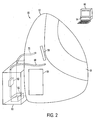
FIG. 2 is a representation of an adult sized plethysmographic chamber and air circulation system of the present invention. -
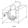
FIG. 3 is a detailed view of one embodiment the air circulation components of the present invention. -
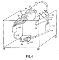
FIG. 4 is a detailed view of another embodiment of the air circulation components of the present invention. - Referring to
FIG. 1 , a representational view of the infant sized plethysmographic measurement chamber and air circulation system is shown.Plethysmographic system 20 is composed ofplethysmographic measurement chamber 22,chamber door assembly 24, plethysmographic measurement components 26 (includingvolume perturbation element 28, and aircirculation component chamber 30. Aircirculation component chamber 30 housesair circulation components 31, which provide the mechanism for air circulation withinchamber 22. -
Plethysmographic measurement components 26 are coupled tocomputer 32, which includes software 34 for controlling the operation ofplethysmographic measurement components 26. - Air
circulation component chamber 30 is coupled tomeasurement chamber 22 viainlet tube 36 andexhaust tube 38.Inlet tube 36 andexhaust tube 38 allow for air to be continuously circulated and renewed withinmeasurement chamber 22 through the operation ofair circulation components 31. As described in more detail in connection with preferred embodiments of the invention,inlet tube 36 andexhaust tube 38 could comprise multiple parallel tubes in accordance with the present invention. Such an arrangement would result in quieter, laminar flow within the tubes, thereby generating less acoustic noise, at the expense of increased flow resistance. - Referring to
FIG. 2 , a representational view of an adult sized plethysmographic measurement chamber and air circulation system is shown.Plethysmographic system 50 is composed ofplethysmographic measurement chamber 52,chamber door 54, plethysmographic measurement components 56 (including volume perturbation element 58), and aircirculation component chamber 60, which houses air circulation components 62.Plethysmographic measurement components 56 are coupled tocomputer 64, which includessoftware 66 for controlling the operation ofplethysmographic measurement components 56. - Air
circulation component chamber 60 is coupled tomeasurement chamber 52 viainlet tube 68 andexhaust tube 70.Inlet tube 68 andexhaust tube 70 allow for air to be continuously renewed and circulated withinmeasurement chamber 52 by air circulation components 62. As described in more detail in connection with preferred embodiments of the invention,inlet tube 68 andexhaust tube 70 could comprise multiple parallel tubes in accordance with the present invention. - One of ordinary skill in the art would understand that air
circulation component chamber 60 could alternatively be housed withinmeasurement chamber 52, so long as air circulation components 62 had access to ambient air outside ofmeasurement chamber 52. - Referring now to
FIG. 3 , a view of one embodiment of the air circulation components of the present invention is described. Pump assembly 80 (shown housed within air circulation component chamber 82) is coupled tomeasurement chamber 84 viainlet tube 86 andexhaust tube 88.Pump assembly 80 both pumps ambient air throughinlet tube 86 intomeasurement chamber 84, and pumps air contaminated with triatomic gasses (such as water vapor and CO2) out ofmeasurement chamber 84 throughexhaust tube 88. Thus, air is continuously circulated and renewed withinmeasurement chamber 84, preventing buildup of triatomic gasses that could affect the accuracy of plethysmographic measurement. - While in a preferred
embodiment pump assembly 80 is housed within aircirculation component chamber 82, one of ordinary skill in the art would recognize thatpump assembly 80 could be physically located anywhere in relation tomeasurement chamber 84, so long aspump assembly 80 provided for circulation and renewal of air withinchamber 84. -
Pump assembly 80 is further comprised of one or more pumps for pumping air into and out ofmeasurement chamber 84. In a preferred embodiment,pump assembly 80 further comprisesinlet 89,inlet pump 90,exhaust 91 andexhaust pump 92.Inlet pump 90 pumps ambient air frominlet 89 throughinlet tube 86 intomeasurement chamber 84, andexhaust pump 92 pumps contaminated air out ofmeasurement chamber 84 throughexhaust tube 88 and outexhaust 91. -
Inlet pump 90 andexhaust pump 92 are preferably turbine or centrifugal pumps. However, one of ordinary skill in the art would recognize that other types of pumps suitable for pumping gasses could be used in accordance with the present invention, including fan pumps, diaphragm pumps, peristaltic pumps, and piston pumps. - Preferably,
inlet pump 90 andexhaust pump 92 are placed at the ends ofinlet tube 86 andexhaust tube 88 distal frommeasurement chamber 84, respectively. This placement allows for maximum attenuation of noise generated byinlet pump 90 andexhaust pump 92. However,inlet pump 90 andexhaust pump 92 may be placed at any point in the airflow betweenmeasurement chamber 84 and atmosphere in accordance with the present invention. - As one of ordinary skill in the art would understand, pump
assembly 80 could also be comprised of a single pump, as opposed to a combination of input and exhaust pumps. While such a pump assembly would result in chamber pressure somewhat different from ambient, this may well be acceptable in some plethysmographic measurement systems. One of ordinary skill in the art would further recognize thatinlet pump 90 andexhaust pump 92 do not have to be placed within a single pump assembly. For example,inlet pump 90 andexhaust pump 92 could be mounted separately within aircirculation component chamber 82. Further, one or both ofinlet pump 90 andexhaust pump 92 could be mounted outside of aircirculation component chamber 82. - It is also preferable that
inlet 89 andexhaust 91 be kept separate from one another. Such a placement ofinlet 89 andexhaust 91 ensures that contaminated air pumped out ofmeasurement chamber 84 is exhausted away frominlet 89, in order to prevent contamination of incoming air by excess CO2 and water vapor being discharged fromexhaust 91. - The physical properties of
inlet tube 86 andexhaust tube 88 are important to maintain the acoustic properties ofmeasurement chamber 84, such that accurate measurement of chamber volume can be attained in spite of the coupling ofmeasurement chamber 84 to the external environment. More particularly, by couplingmeasurement chamber 84 to the environment, acoustic noise could pass throughinlet tube 86 andexhaust tube 88 intomeasurement chamber 84, thereby affecting the accuracy of the body composition measurement. Further, acoustic energy at the frequency of perturbation could also leak outsidemeasurement chamber 84, again affecting the accuracy of measurement. - However, the air within
inlet tube 86 andexhaust tube 88 possesses inertia, which acts to resist movement of air within the tubes in response to pressure fluctuations (such as acoustic noise fromoutside measurement chamber 84, or the periodic perturbations generated during plethysmographic measurement). This property can be maximized through selection of the length ofinlet tube 86 andexhaust tube 88. - As a first approximation,
measurement chamber 84 and inlet tube 86 (or exhaust tube 88) can be modeled in a combined manner as a Helmholtz resonator. The Helmholtz resonator realized by the combination ofmeasurement chamber 84 andinlet tube 86/exhaust tube 88 acts as a low-pass filter, attenuating acoustic noise above the resonant frequency of the system (which is inversely proportional to the square root of the length of the tube). Thus, the length ofinlet tube 86 andexhaust tube 88 can be selected such that the acoustic low-pass filter properties of the chamber/tube system attenuate frequencies at or above the perturbation frequency. In a preferred embodiment of the invention, the lengths of the inlet tubes and exhaust tubes were selected such that the resonant frequency of the chamber/tube system was an order of magnitude below the perturbation frequency. - As a second approximation, the acoustic properties of
inlet tube 86 andexhaust tube 88 can be looked at independently frommeasurement chamber 84. In so doing, the length of the tube would preferably be set at one-quarter the wavelength corresponding to the perturbation frequency in order to minimize transmission of pressure fluctuations throughinlet tube 86 andexhaust tube 88 at the perturbation frequency. While adopting this model has been found to yield some benefit, in practice it has been found that simply ensuring thatinlet tube 86 andexhaust tube 88 are of sufficient length to attenuate periodic signals at or above the frequency of perturbation (typically, between 3 Hz and 20 Hz, depending on the type of plethysmographic measurement system used) produces satisfactory results. - In a preferred embodiment, air
circulation component chamber 82 further includesheater element 98,temperature monitoring circuitry 100, and controlledtemperature inlet 102. In this embodiment,temperature monitoring circuitry 100 monitors the temperature of controlledtemperature inlet 102, and varies the operation ofheater element 98 to maintain a constant temperature within controlledtemperature inlet 102. Controlledtemperature inlet 102 acts as the source of air forinlet pump 90; thus, air is pumped from temperature controlledinlet 102 throughinlet tube 86 intomeasurement chamber 84 by means ofinlet pump 90. By providing for a controlled temperature environment withinmeasurement chamber 84, the potential effects of temperature fluctuation inmeasurement chamber 84 due to body heat generated by the test subject are minimized. - Alternatively,
heater element 98 can be used to heat the air withininlet tube 86 via conduction. In this embodiment,inlet pump 90 draws air throughinlet 89 from the environment outside aircirculation component chamber 82.Temperature monitoring circuitry 100 monitors the temperature of air withininlet tube 86, and varies the operation ofheater element 98 to maintain a constant temperature of incoming air withininlet tube 86. - As another alternative,
heater element 98 could be coupled toinlet pump 90, and used to directly heat the air withininlet tube 86. - It has also been found in practice that the flow rate of the air circulation system of the present invention can have an effect on the calibration of the plethysmographic measurement system. Systems and methods for calibrating plethysmographic measurement chambers are described in co-pending
U.S. Patent Application No. 10/036,161 , entitled "Calibration Methods and Apparatus for Plethysmographic Measurement Chambers," applied for by Philip Dempster, and filed on December 31, 2001 (attorney internal docket no. LM-003). - More particularly, as flow rate varies, dynamic resistance to pressure fluctuations also varies (under turbulent conditions). Stability of the system therefore can be improved by controlling flow rate. Thus, in a preferred embodiment, coupled to
inlet tube 86 and/orexhaust tube 88 are one ormore pressure transducers 104, which monitor the pressure drop across the inlet and/or exhaust tube.Pressure transducers 104 are further coupled to pumpassembly 80 viafeedback circuit 106.Feedback circuit 106, based on the input frompressure transducers 104, controls the operation ofpump assembly 80 to provide for constant flow rate in the air circulation system. In a preferred embodiment,feedback circuit 106 varies the electrical power to pumpassembly 80 to control flow rate. - One of ordinary skill in the art would recognize that other methods of maintaining flow rate may be used. For example, if
pump assembly 80 comprises one or more rotary pumps, constant flow rate may be achieved by controlling the angular velocity of the rotary pump(s). One of ordinary skill in the art would also recognize that pressure drop may be measured across part or all of the tubing system comprised ofinlet tube 86 andexhaust tube 88. - Further, while the particular flow rate selected must be sufficient to maintain acceptable levels of CO2 and water vapor in
measurement chamber 84, lower flow rates result in less acoustic noise being generated by the air circulation system. Thus, the particular flow rate selected should balance these two competing considerations. In practice, a wide range of flow rates were found to work successfully. - Referring now to
FIG. 4 , a detailed view of a second embodiment of the air circulation components of the present invention is described.Pump assembly 120 includesinlet pump 122 andexhaust pump 124.Inlet pump 122 is coupled viainlet manifold tube 126 toinlet manifold 128.Inlet manifold 128 is coupled via parallelinlet chamber tubes measurement chamber 138. Similarly,exhaust pump 124 is coupled viaexhaust manifold tube 140 toexhaust manifold 142.Exhaust manifold 142 is coupled via parallelexhaust chamber tubes measurement chamber 138. - As with the previously described embodiments,
pump assembly 120 both pumps ambient air through inletmanifold tube 126,inlet manifold 128, andinlet chamber tubes measurement chamber 138, and pumps air contaminated with triatomic gasses (such as water vapor and CO2) out ofmeasurement chamber 138 throughexhaust chamber tubes exhaust manifold 142, andexhaust manifold tube 140. By coupling bothinlet manifold 128 andexhaust manifold 142 withmeasurement chamber 138 via multiple, parallel tubes, this embodiment both provides for reduced flow resistance in comparison to full lengths of multiple parallel tubes between the manifolds andmeasurement chamber 138, while at the same time providing quieter, laminar flow at the entry ofmeasurement chamber 138 compared to the single inlet and exhaust tube embodiment described in connection withFIG. 3 . - While preferred illustrative embodiments of the invention are described above, it will be apparent to one skilled in the art that various changes and modifications may be made therein without departing from the invention. The appended claims are intended to cover all such changes and modifications that fall within the scope of the invention.
Claims (42)
- A plethysmographic measurement system, comprising:a plethysmographic measurement chamber (22; 52; 84; 138); andplethysmographic measurement components (26; 56) coupled to the measurement chamber,an air circulation system coupled between the measurement chamber and the environment outside the measurement chamber,wherein the measurement components comprise:a volume perturbation element (28; 58) configured to change the volume of the measurement chamber andmeans (104; 106) for determining pressure within the chamber; andwherein the air circulation system is configured to renew air within the measurement chamber using air from the environment outside the chamber during plethysmographic measurement.
- The system of claim 1, wherein the measurement components are housed within the measurement chamber.
- The system of claim 1, further comprising a chamber door (24; 54) coupled to the measurement chamber.
- The system of claim 1, wherein the means for determining pressure comprises one or more pressure transducers (104).
- The system of claim 1, wherein the volume perturbation element is an oscillating diaphragm.
- The system of claim 1, wherein the volume perturbation element generates pressure oscillations within the measurement chamber at a first frequency.
- The system of claim 1, wherein the frequency is between 3 and 20 Hz.
- The system of claim 1, wherein the air circulation system comprises:a pump assembly (80; 120);an inlet tub (36; 68; 86) coupled between the measurement chamber and the pump assembly, andan exhaust tube (38; 70; 88) coupled between the measurement chamber and pump assembly.
- The system of claim 8, wherein the pump assembly comprises an inlet pump (90; 122) and an exhaust pump (92; 124).
- The system of claim 8, wherein the pump assembly comprises one or more rotary pumps, and/or one or more turbine pumps and/or one or more centrifugal pumps, and/or one or more fan pumps, and/or one or more diaphragm pumps, and/or one or more piston pumps, and/or one or more peristaltic pumps.
- The system of claim 8, further comprising: a plurality of parallel inlet tubes (36; 38), and/or a plurality of parallel exhaust tubes (38; 70).
- The system of claim 9, wherein the inlet pump is placed at the end of the inlet tube (86) distal from the measurement chamber (84).
- The system of claim 9, wherein the exhaust pump is placed at the end of the exhaust tube (88) distal from the measurement chamber (84).
- The system of claim 1, wherein the air circulation system (31) comprises:a pump assembly (80; 120);an inlet manifold tube (126) coupled between the pump assembly (120) and an inlet manifold (128),an inlet chamber tube coupled between the inlet manifold (128) and the measurement chamber (138),an exhaust manifold tube (140) coupled between an exhaust manifold (142) and the pump assembly (122), andan exhaust chamber tube coupled between the exhaust manifold (142) and the measurement chamber (138).
- The system of claim 14, further comprising: a plurality of parallel tubes (144; 146; 148; 150) coupled between the inlet manifold and the measurement chamber.
- The system of claim 14 further comprising: a plurality of parallel tubes (130; 132; 134; 136) coupled between the exhaust manifold and the measurement chamber.
- The system of claim 14, wherein the measurement components (26; 56) comprise:a volume perturbation element (28; 58); anda pressure transducer (104).
- The system of claim 17, wherein the volume perturbation element generates volume perturbations at a first perturbation frequency.
- The system of claim 18, wherein the inlet tube and exhaust tube attenuate noise at the perturbation frequency.
- The system of claim 19, wherein the length of the inlet tube is one quarter of a wavelength corresponding to the perturbation frequency.
- The system of claim 19, wherein the length of the exhaust tube is one quarter of a wavelength corresponding to the perturbation frequency.
- The system of claim 8, further comprising:a pressure transducer (104); anda feedback circuit (106) coupled between the pump assembly (80) and the pressure transducer (104), wherein the pressure transducer measures a flow rate of the air circulation system, and wherein the feedback circuit maintains a constant flow rate in the air circulation system.
- The system of claim 22, wherein the pressure transducer is coupled to the inlet tube or to the exhaust tube.
- The system of claim 22 or 23, wherein the feedback circuit varies the operation of the pump assembly.
- The system of claim 24, wherein the pump assembly comprises one or more rotary pumps, and wherein the feedback circuit varies the angular velocity of the one or more rotary pumps.
- The system of claim 1, further comprising:a controlled temperature environment, wherein the air circulation system pumps air from the controlled temperature environment into the chamber.
- The system of claim 26, wherein the air circulation system comprises:a pump assembly coupled to the controlled temperature environment;an inlet tube coupled between the measurement chamber and the pump assembly, andan exhaust tube coupled between the measurement chamber and pump assembly.
- The system of claim 26 or 27, wherein the controlled temperature environment comprises:a heater element (98); andtemperature monitoring circuitry (100) coupled to the heater element.
- The system of claim 28, wherein the temperature monitoring circuitry maintains a constant temperature within the controlled temperature environment.
- The system of claim 28 or 29, wherein the temperature monitoring circuit controls the operation of the heater element.
- The system of claim 1, further comprising:a pump assembly (80) coupled to the controlled temperature environment;an inlet tube (86) coupled between the measurement chamber and the pump assembly, andan exhaust tube (88) coupled between the measurement chamber and the pump assembly;a heater element (98); andtemperature monitoring circuitry (100) coupled to the heater element.
- The system of claim 31, wherein the temperature monitoring circuitry maintains a constant air temperature within the inlet tube.
- The system of claim 31 or 32, wherein the temperature monitoring circuit controls the operation of the heater element.
- A method of conducting plethysmographic measurement of a test subject, comprising:placing the subject to be measured in a plethysmographic measurement chamber (22; 52; 84; 138), sealing said chamber; and conducting plethysmographic measurement of the subject, renewing air within the chamber using air from the environment outside the chamber, wherein conducting plethysmographic measurement comprises:generating pressure oscillations within the chamber;measuring the amplitude of the pressure oscillations;calculating a volume of air within the chamber based on the measured pressure oscillations; anddetermining a body composition of the test subject based on the calculated volume of air within the chamber.
- The method of claim 34, wherein generating pressure oscillations comprises:oscillating a diaphragm at a fixed frequency.
- The method of claim 34 or 35, wherein renewing air through the chamber comprises:pumping air though an inlet tube (86) into the chamber; andpumping air through an exhaust tube (88) out of the measurement chamber.
- The method of claim 36, wherein pumping air through an inlet tube comprises:establishing a controlled temperature environment; andpumping air from the controlled temperature environment through the inlet tube.
- The method of claim 37, wherein establishing a controlled temperature environment comprises:measuring the temperature of an enclosed environment;comparing the measured temperature to a desired control temperature;varying the operation of a heater element (98) in response to the comparison of the measured temperature to the desired temperature.
- The method of claim 37 or 38, further comprising:heating the air with the inlet tube to a controlled temperature.
- The method of claim 39, wherein heating the air with the inlet tube to a controlled temperature comprises:measuring the temperature of air within the inlet tube;comparing the measured temperature to a desired control temperature; andvarying the operation of a heater element (98) in response to the comparison of the measured temperature to the desired temperature.
- The method of any one of claims 34 to 40, further comprising:maintaining a constant flow rate of air being circulated through the chamber.
- The method of claim 41, wherein maintaining a constant flow rate comprises:measuring a flow rate;comparing the measured flow rate to a desired flow rate, andvarying the operation of an air pump in response to comparing the measured flow rate to the control flow rate.
Applications Claiming Priority (2)
| Application Number | Priority Date | Filing Date | Title |
|---|---|---|---|
| US10/402,225 US7022087B2 (en) | 2003-03-26 | 2003-03-26 | Air circulation apparatus and methods for plethysmographic measurement chambers |
| PCT/US2004/009226 WO2004088254A2 (en) | 2003-03-26 | 2004-03-24 | Air circulation apparatus and methods for plethysmographic measurement chambers |
Publications (3)
| Publication Number | Publication Date |
|---|---|
| EP1610680A2 EP1610680A2 (en) | 2006-01-04 |
| EP1610680A4 EP1610680A4 (en) | 2007-10-31 |
| EP1610680B1 true EP1610680B1 (en) | 2015-12-23 |
Family
ID=32989648
Family Applications (1)
| Application Number | Title | Priority Date | Filing Date |
|---|---|---|---|
| EP04758369.5A Expired - Lifetime EP1610680B1 (en) | 2003-03-26 | 2004-03-24 | Air circulation apparatus and methods for plethysmographic measurement chambers |
Country Status (5)
| Country | Link |
|---|---|
| US (1) | US7022087B2 (en) |
| EP (1) | EP1610680B1 (en) |
| JP (2) | JP4521395B2 (en) |
| CA (1) | CA2519950C (en) |
| WO (1) | WO2004088254A2 (en) |
Families Citing this family (15)
| Publication number | Priority date | Publication date | Assignee | Title |
|---|---|---|---|---|
| EP1878385A1 (en) * | 2006-07-13 | 2008-01-16 | Institut National De La Sante Et De La Recherche Medicale (Inserm) | Device for collecting physiological information of an animal, and corresponding method |
| US20080029173A1 (en) * | 2006-08-07 | 2008-02-07 | Diperna Paul Mario | Variable flow reshapable flow restrictor apparatus and related methods |
| US8550127B2 (en) | 2007-08-13 | 2013-10-08 | Unidense Technology Gmbh | Catalyst loading system |
| US8986253B2 (en) | 2008-01-25 | 2015-03-24 | Tandem Diabetes Care, Inc. | Two chamber pumps and related methods |
| US20100036327A1 (en) * | 2008-08-08 | 2010-02-11 | Tandem Diabetes Care, Inc. | Flow prevention, regulation, and safety devices and related methods |
| US8408421B2 (en) | 2008-09-16 | 2013-04-02 | Tandem Diabetes Care, Inc. | Flow regulating stopcocks and related methods |
| CA2737461A1 (en) | 2008-09-19 | 2010-03-25 | Tandem Diabetes Care, Inc. | Solute concentration measurement device and related methods |
| EP2724739B1 (en) | 2009-07-30 | 2015-07-01 | Tandem Diabetes Care, Inc. | Portable infusion pump system |
| US9180242B2 (en) | 2012-05-17 | 2015-11-10 | Tandem Diabetes Care, Inc. | Methods and devices for multiple fluid transfer |
| US9555186B2 (en) | 2012-06-05 | 2017-01-31 | Tandem Diabetes Care, Inc. | Infusion pump system with disposable cartridge having pressure venting and pressure feedback |
| US9173998B2 (en) | 2013-03-14 | 2015-11-03 | Tandem Diabetes Care, Inc. | System and method for detecting occlusions in an infusion pump |
| US9226695B2 (en) | 2013-07-02 | 2016-01-05 | Near Margalit | Dual chamber volume measurement apparatus and methods of making and using the same |
| JP6383242B2 (en) * | 2014-10-20 | 2018-08-29 | 日本気圧バルク工業株式会社 | High pressure low pressure room |
| US20160120443A1 (en) * | 2014-11-03 | 2016-05-05 | Near Margalit | Single Chamber Volume Measurement Apparatus and Methods of Making and Using the Same |
| CN119745366A (en) * | 2024-12-29 | 2025-04-04 | 深圳市美好创亿医疗科技股份有限公司 | A plethysmography box |
Citations (1)
| Publication number | Priority date | Publication date | Assignee | Title |
|---|---|---|---|---|
| US5379777A (en) * | 1994-01-07 | 1995-01-10 | Buxco Electronics, Inc. | Whole body plethysmograph for non-invasive pulmonary measurements of unrestrained small animals |
Family Cites Families (24)
| Publication number | Priority date | Publication date | Assignee | Title |
|---|---|---|---|---|
| DE1466840C3 (en) * | 1964-12-11 | 1981-10-01 | Jaeger, Erich, 8700 Würzburg | Plethysmograph |
| US3769834A (en) * | 1971-11-18 | 1973-11-06 | Nasa | Whole body measurement systems |
| US4184371A (en) | 1977-11-09 | 1980-01-22 | Roland Brachet | Apparatus for measuring the density of a body |
| NL7904400A (en) | 1979-06-05 | 1980-12-09 | Rijkslandbouwhogeschool | METHOD FOR MEASURING THE VOLUME OF FIXED BODIES AND MEASUREMENT AND / OR REFERENCE CHAMBER FOR CARRYING OUT THIS METHOD |
| NL8005145A (en) | 1980-09-12 | 1982-04-01 | Tno | DEVICE FOR INDIRECT, NON-INVASIVE, CONTINUOUS MEASUREMENT OF BLOOD PRESSURE. |
| NL8104879A (en) | 1981-10-28 | 1983-05-16 | Tno | METHOD AND APPARATUS FOR CONTROLLING THE CUFF PRESSURE WHEN MEASURING THE FINGER BLOOD PRESSURE WITH A PHOTO-ELECTRICAL PLETHYSMOGRAPH. |
| US4640130A (en) | 1984-10-29 | 1987-02-03 | Baylor College Of Medicine | Method and apparatus for acoustically measuring the volume of an object |
| US4587967A (en) * | 1985-07-09 | 1986-05-13 | Lifecare Services, Inc. | Oxygen enriched reciprocating piston respirator |
| US4676253A (en) | 1985-07-18 | 1987-06-30 | Doll Medical Research, Inc. | Method and apparatus for noninvasive determination of cardiac output |
| US4671297A (en) * | 1985-10-25 | 1987-06-09 | Schulze Jr Karl F | Method and apparatus for monitoring infants on assisted ventilation |
| US4888718A (en) | 1987-02-25 | 1989-12-19 | Kubushiki Kaisha Kosumo Keiki | Volume measuring apparatus and method |
| JPH01136027A (en) * | 1987-11-24 | 1989-05-29 | Techno Japan Kk | Volume measuring apparatus |
| US4972842A (en) * | 1988-06-09 | 1990-11-27 | Vital Signals, Inc. | Method and apparatus for precision monitoring of infants on assisted ventilation |
| US5105825A (en) * | 1990-07-10 | 1992-04-21 | Life Measurement Instruments | Method and apparatus for volume measurement and body composition estimation |
| JP3038638B2 (en) * | 1994-03-22 | 2000-05-08 | リオン株式会社 | Hearing test room |
| US5450750A (en) | 1994-07-01 | 1995-09-19 | Abler Data System | Body volume measurement chamber |
| US5632270A (en) * | 1994-09-12 | 1997-05-27 | Puritan-Bennett Corporation | Method and apparatus for control of lung ventilator exhalation circuit |
| DE19541900C2 (en) | 1994-11-12 | 1999-05-27 | Ganshorn Med Electronic Gmbh | Whole body plethysmograph with calibration of the manometer |
| NO319498B1 (en) * | 1996-07-30 | 2005-08-22 | Weinmann G Geraete Med | Respiratory apparatus for the therapy of sleep apnea ± and methods of controlling it. |
| SE9704663D0 (en) * | 1997-12-15 | 1997-12-15 | Siemens Elema Ab | Fan system |
| JP4017093B2 (en) * | 1999-09-28 | 2007-12-05 | 株式会社前川製作所 | Device for volume measurement of continuum samples in containers |
| US6778926B2 (en) * | 2001-12-31 | 2004-08-17 | Life Measurement, Inc. | Calibration methods and apparatus for plethysmographic measurement chambers |
| US6702764B2 (en) * | 2001-12-31 | 2004-03-09 | Life Measurement, Inc. | Apparatus and methods for plethysmographic measurement of infant body composition |
| US6702661B1 (en) * | 2002-11-25 | 2004-03-09 | Lucent Technologies Inc. | Cooling method and apparatus |
-
2003
- 2003-03-26 US US10/402,225 patent/US7022087B2/en not_active Expired - Lifetime
-
2004
- 2004-03-24 WO PCT/US2004/009226 patent/WO2004088254A2/en not_active Ceased
- 2004-03-24 JP JP2006509319A patent/JP4521395B2/en not_active Expired - Lifetime
- 2004-03-24 EP EP04758369.5A patent/EP1610680B1/en not_active Expired - Lifetime
- 2004-03-24 CA CA2519950A patent/CA2519950C/en not_active Expired - Lifetime
-
2007
- 2007-03-20 JP JP2007073723A patent/JP2007229484A/en active Pending
Patent Citations (1)
| Publication number | Priority date | Publication date | Assignee | Title |
|---|---|---|---|---|
| US5379777A (en) * | 1994-01-07 | 1995-01-10 | Buxco Electronics, Inc. | Whole body plethysmograph for non-invasive pulmonary measurements of unrestrained small animals |
Also Published As
| Publication number | Publication date |
|---|---|
| JP4521395B2 (en) | 2010-08-11 |
| US7022087B2 (en) | 2006-04-04 |
| CA2519950C (en) | 2012-05-29 |
| WO2004088254A3 (en) | 2005-03-10 |
| JP2007229484A (en) | 2007-09-13 |
| US20040193074A1 (en) | 2004-09-30 |
| CA2519950A1 (en) | 2004-10-14 |
| EP1610680A2 (en) | 2006-01-04 |
| EP1610680A4 (en) | 2007-10-31 |
| JP2006523131A (en) | 2006-10-12 |
| WO2004088254A2 (en) | 2004-10-14 |
Similar Documents
| Publication | Publication Date | Title |
|---|---|---|
| JP2007229484A (en) | Air circulation apparatus and methods for plethysmographic measurement chambers | |
| McCRORY et al. | Evaluation of a new air displacement plethysmograph for measuring human body composition | |
| US6066101A (en) | Airflow perturbation device and method for measuring respiratory resistance | |
| US11103151B2 (en) | Deriving individual thoracic parameters of a subject | |
| EP1631340B1 (en) | Portable respiratory diagnostic device | |
| EP1374767A2 (en) | Respiration function measuring system and its application | |
| US3598111A (en) | Technique and apparatus for measuring and monitoring the mechanical impedance of body tissues and organ systems | |
| EP3410933B1 (en) | Forced oscillation technique based lung function testing | |
| JP6461334B2 (en) | Electronics | |
| US7094208B2 (en) | Spirometer | |
| US20160150998A1 (en) | Methods and devices for determining pulmonary measurement | |
| GB2388665A (en) | Electronic spirometer having pressure sensor coupled to inlet tube | |
| WO2002071017A2 (en) | A system and method of metabolic rate measurement | |
| JP2009545356A (en) | Sensor that detects the passage of pulse waves from the patient's arterial system | |
| CN105722460A (en) | Determining respiratory parameters | |
| US12582376B2 (en) | Constitutive equation for non-invasive blood pressure measurement systems and methods | |
| JPH05508787A (en) | Methods and devices for human body volume measurement | |
| US20130150747A1 (en) | System and method for measuring the mechanical impedance of the respiratory system | |
| JP2005505373A (en) | System and method for measuring the degree of physical activity of an object | |
| WO2020093177A1 (en) | Method and apparatus for continuous management of airway pressure for detection and/or prediction of respiratory failure | |
| EP3731750A1 (en) | Expiratory flow limitation detection via flow resistor adjustment | |
| Agarwal et al. | Design and development of a low-cost spirometer with an embedded web server | |
| US6702764B2 (en) | Apparatus and methods for plethysmographic measurement of infant body composition | |
| JP2006150088A (en) | Calibration method and apparatus for plethysmographic measurement chamber | |
| CN113017698A (en) | Wearable heart-lung function monitor |
Legal Events
| Date | Code | Title | Description |
|---|---|---|---|
| PUAI | Public reference made under article 153(3) epc to a published international application that has entered the european phase |
Free format text: ORIGINAL CODE: 0009012 |
|
| 17P | Request for examination filed |
Effective date: 20051017 |
|
| AK | Designated contracting states |
Kind code of ref document: A2 Designated state(s): AT BE BG CH CY CZ DE DK EE ES FI FR GB GR HU IE IT LI LU MC NL PL PT RO SE SI SK TR |
|
| AX | Request for extension of the european patent |
Extension state: AL LT LV MK |
|
| DAX | Request for extension of the european patent (deleted) | ||
| A4 | Supplementary search report drawn up and despatched |
Effective date: 20071002 |
|
| 17Q | First examination report despatched |
Effective date: 20110708 |
|
| RAP1 | Party data changed (applicant data changed or rights of an application transferred) |
Owner name: COSMED USA, INC. |
|
| GRAP | Despatch of communication of intention to grant a patent |
Free format text: ORIGINAL CODE: EPIDOSNIGR1 |
|
| INTG | Intention to grant announced |
Effective date: 20150629 |
|
| GRAS | Grant fee paid |
Free format text: ORIGINAL CODE: EPIDOSNIGR3 |
|
| GRAA | (expected) grant |
Free format text: ORIGINAL CODE: 0009210 |
|
| AK | Designated contracting states |
Kind code of ref document: B1 Designated state(s): AT BE BG CH CY CZ DE DK EE ES FI FR GB GR HU IE IT LI LU MC NL PL PT RO SE SI SK TR |
|
| REG | Reference to a national code |
Ref country code: GB Ref legal event code: FG4D |
|
| REG | Reference to a national code |
Ref country code: CH Ref legal event code: EP |
|
| REG | Reference to a national code |
Ref country code: IE Ref legal event code: FG4D |
|
| REG | Reference to a national code |
Ref country code: AT Ref legal event code: REF Ref document number: 766155 Country of ref document: AT Kind code of ref document: T Effective date: 20160115 |
|
| REG | Reference to a national code |
Ref country code: DE Ref legal event code: R096 Ref document number: 602004048396 Country of ref document: DE |
|
| REG | Reference to a national code |
Ref country code: FR Ref legal event code: PLFP Year of fee payment: 13 |
|
| REG | Reference to a national code |
Ref country code: NL Ref legal event code: MP Effective date: 20151223 |
|
| REG | Reference to a national code |
Ref country code: AT Ref legal event code: MK05 Ref document number: 766155 Country of ref document: AT Kind code of ref document: T Effective date: 20151223 |
|
| PG25 | Lapsed in a contracting state [announced via postgrant information from national office to epo] |
Ref country code: FI Free format text: LAPSE BECAUSE OF FAILURE TO SUBMIT A TRANSLATION OF THE DESCRIPTION OR TO PAY THE FEE WITHIN THE PRESCRIBED TIME-LIMIT Effective date: 20151223 Ref country code: GR Free format text: LAPSE BECAUSE OF FAILURE TO SUBMIT A TRANSLATION OF THE DESCRIPTION OR TO PAY THE FEE WITHIN THE PRESCRIBED TIME-LIMIT Effective date: 20160324 Ref country code: SE Free format text: LAPSE BECAUSE OF FAILURE TO SUBMIT A TRANSLATION OF THE DESCRIPTION OR TO PAY THE FEE WITHIN THE PRESCRIBED TIME-LIMIT Effective date: 20151223 Ref country code: NL Free format text: LAPSE BECAUSE OF FAILURE TO SUBMIT A TRANSLATION OF THE DESCRIPTION OR TO PAY THE FEE WITHIN THE PRESCRIBED TIME-LIMIT Effective date: 20151223 |
|
| PG25 | Lapsed in a contracting state [announced via postgrant information from national office to epo] |
Ref country code: IT Free format text: LAPSE BECAUSE OF FAILURE TO SUBMIT A TRANSLATION OF THE DESCRIPTION OR TO PAY THE FEE WITHIN THE PRESCRIBED TIME-LIMIT Effective date: 20151223 Ref country code: CZ Free format text: LAPSE BECAUSE OF FAILURE TO SUBMIT A TRANSLATION OF THE DESCRIPTION OR TO PAY THE FEE WITHIN THE PRESCRIBED TIME-LIMIT Effective date: 20151223 Ref country code: ES Free format text: LAPSE BECAUSE OF FAILURE TO SUBMIT A TRANSLATION OF THE DESCRIPTION OR TO PAY THE FEE WITHIN THE PRESCRIBED TIME-LIMIT Effective date: 20151223 |
|
| PG25 | Lapsed in a contracting state [announced via postgrant information from national office to epo] |
Ref country code: RO Free format text: LAPSE BECAUSE OF FAILURE TO SUBMIT A TRANSLATION OF THE DESCRIPTION OR TO PAY THE FEE WITHIN THE PRESCRIBED TIME-LIMIT Effective date: 20151223 Ref country code: BE Free format text: LAPSE BECAUSE OF NON-PAYMENT OF DUE FEES Effective date: 20160331 Ref country code: SK Free format text: LAPSE BECAUSE OF FAILURE TO SUBMIT A TRANSLATION OF THE DESCRIPTION OR TO PAY THE FEE WITHIN THE PRESCRIBED TIME-LIMIT Effective date: 20151223 Ref country code: PL Free format text: LAPSE BECAUSE OF FAILURE TO SUBMIT A TRANSLATION OF THE DESCRIPTION OR TO PAY THE FEE WITHIN THE PRESCRIBED TIME-LIMIT Effective date: 20151223 Ref country code: PT Free format text: LAPSE BECAUSE OF FAILURE TO SUBMIT A TRANSLATION OF THE DESCRIPTION OR TO PAY THE FEE WITHIN THE PRESCRIBED TIME-LIMIT Effective date: 20160426 Ref country code: AT Free format text: LAPSE BECAUSE OF FAILURE TO SUBMIT A TRANSLATION OF THE DESCRIPTION OR TO PAY THE FEE WITHIN THE PRESCRIBED TIME-LIMIT Effective date: 20151223 Ref country code: EE Free format text: LAPSE BECAUSE OF FAILURE TO SUBMIT A TRANSLATION OF THE DESCRIPTION OR TO PAY THE FEE WITHIN THE PRESCRIBED TIME-LIMIT Effective date: 20151223 |
|
| REG | Reference to a national code |
Ref country code: DE Ref legal event code: R097 Ref document number: 602004048396 Country of ref document: DE |
|
| PLBE | No opposition filed within time limit |
Free format text: ORIGINAL CODE: 0009261 |
|
| STAA | Information on the status of an ep patent application or granted ep patent |
Free format text: STATUS: NO OPPOSITION FILED WITHIN TIME LIMIT |
|
| PG25 | Lapsed in a contracting state [announced via postgrant information from national office to epo] |
Ref country code: LU Free format text: LAPSE BECAUSE OF FAILURE TO SUBMIT A TRANSLATION OF THE DESCRIPTION OR TO PAY THE FEE WITHIN THE PRESCRIBED TIME-LIMIT Effective date: 20160324 Ref country code: MC Free format text: LAPSE BECAUSE OF FAILURE TO SUBMIT A TRANSLATION OF THE DESCRIPTION OR TO PAY THE FEE WITHIN THE PRESCRIBED TIME-LIMIT Effective date: 20151223 Ref country code: DK Free format text: LAPSE BECAUSE OF FAILURE TO SUBMIT A TRANSLATION OF THE DESCRIPTION OR TO PAY THE FEE WITHIN THE PRESCRIBED TIME-LIMIT Effective date: 20151223 |
|
| REG | Reference to a national code |
Ref country code: CH Ref legal event code: PL |
|
| 26N | No opposition filed |
Effective date: 20160926 |
|
| REG | Reference to a national code |
Ref country code: IE Ref legal event code: MM4A |
|
| PG25 | Lapsed in a contracting state [announced via postgrant information from national office to epo] |
Ref country code: BE Free format text: LAPSE BECAUSE OF FAILURE TO SUBMIT A TRANSLATION OF THE DESCRIPTION OR TO PAY THE FEE WITHIN THE PRESCRIBED TIME-LIMIT Effective date: 20151223 |
|
| PG25 | Lapsed in a contracting state [announced via postgrant information from national office to epo] |
Ref country code: CH Free format text: LAPSE BECAUSE OF NON-PAYMENT OF DUE FEES Effective date: 20160331 Ref country code: IE Free format text: LAPSE BECAUSE OF NON-PAYMENT OF DUE FEES Effective date: 20160324 Ref country code: LI Free format text: LAPSE BECAUSE OF NON-PAYMENT OF DUE FEES Effective date: 20160331 |
|
| PG25 | Lapsed in a contracting state [announced via postgrant information from national office to epo] |
Ref country code: SI Free format text: LAPSE BECAUSE OF FAILURE TO SUBMIT A TRANSLATION OF THE DESCRIPTION OR TO PAY THE FEE WITHIN THE PRESCRIBED TIME-LIMIT Effective date: 20151223 |
|
| REG | Reference to a national code |
Ref country code: FR Ref legal event code: PLFP Year of fee payment: 14 |
|
| REG | Reference to a national code |
Ref country code: FR Ref legal event code: PLFP Year of fee payment: 15 |
|
| PG25 | Lapsed in a contracting state [announced via postgrant information from national office to epo] |
Ref country code: HU Free format text: LAPSE BECAUSE OF FAILURE TO SUBMIT A TRANSLATION OF THE DESCRIPTION OR TO PAY THE FEE WITHIN THE PRESCRIBED TIME-LIMIT; INVALID AB INITIO Effective date: 20040324 Ref country code: CY Free format text: LAPSE BECAUSE OF FAILURE TO SUBMIT A TRANSLATION OF THE DESCRIPTION OR TO PAY THE FEE WITHIN THE PRESCRIBED TIME-LIMIT Effective date: 20151223 |
|
| PG25 | Lapsed in a contracting state [announced via postgrant information from national office to epo] |
Ref country code: TR Free format text: LAPSE BECAUSE OF FAILURE TO SUBMIT A TRANSLATION OF THE DESCRIPTION OR TO PAY THE FEE WITHIN THE PRESCRIBED TIME-LIMIT Effective date: 20151223 |
|
| PG25 | Lapsed in a contracting state [announced via postgrant information from national office to epo] |
Ref country code: BG Free format text: LAPSE BECAUSE OF FAILURE TO SUBMIT A TRANSLATION OF THE DESCRIPTION OR TO PAY THE FEE WITHIN THE PRESCRIBED TIME-LIMIT Effective date: 20151223 |
|
| PGFP | Annual fee paid to national office [announced via postgrant information from national office to epo] |
Ref country code: FR Payment date: 20230208 Year of fee payment: 20 |
|
| PGFP | Annual fee paid to national office [announced via postgrant information from national office to epo] |
Ref country code: GB Payment date: 20230202 Year of fee payment: 20 Ref country code: DE Payment date: 20230125 Year of fee payment: 20 |
|
| REG | Reference to a national code |
Ref country code: DE Ref legal event code: R071 Ref document number: 602004048396 Country of ref document: DE |
|
| REG | Reference to a national code |
Ref country code: GB Ref legal event code: PE20 Expiry date: 20240323 |
|
| PG25 | Lapsed in a contracting state [announced via postgrant information from national office to epo] |
Ref country code: GB Free format text: LAPSE BECAUSE OF EXPIRATION OF PROTECTION Effective date: 20240323 |