EP1610646B1 - A backpack for harvesting electrical energy during walking and for minimizing shoulder strain - Google Patents
A backpack for harvesting electrical energy during walking and for minimizing shoulder strain Download PDFInfo
- Publication number
- EP1610646B1 EP1610646B1 EP04757536A EP04757536A EP1610646B1 EP 1610646 B1 EP1610646 B1 EP 1610646B1 EP 04757536 A EP04757536 A EP 04757536A EP 04757536 A EP04757536 A EP 04757536A EP 1610646 B1 EP1610646 B1 EP 1610646B1
- Authority
- EP
- European Patent Office
- Prior art keywords
- load
- backpack
- frame
- storage bag
- suspended
- Prior art date
- Legal status (The legal status is an assumption and is not a legal conclusion. Google has not performed a legal analysis and makes no representation as to the accuracy of the status listed.)
- Expired - Lifetime
Links
Images













Classifications
-
- A—HUMAN NECESSITIES
- A45—HAND OR TRAVELLING ARTICLES
- A45F—TRAVELLING OR CAMP EQUIPMENT: SACKS OR PACKS CARRIED ON THE BODY
- A45F3/00—Travelling or camp articles; Sacks or packs carried on the body
- A45F3/04—Sacks or packs carried on the body by means of two straps passing over the two shoulders
- A45F3/08—Carrying-frames; Frames combined with sacks
-
- F—MECHANICAL ENGINEERING; LIGHTING; HEATING; WEAPONS; BLASTING
- F03—MACHINES OR ENGINES FOR LIQUIDS; WIND, SPRING, OR WEIGHT MOTORS; PRODUCING MECHANICAL POWER OR A REACTIVE PROPULSIVE THRUST, NOT OTHERWISE PROVIDED FOR
- F03G—SPRING, WEIGHT, INERTIA OR LIKE MOTORS; MECHANICAL-POWER PRODUCING DEVICES OR MECHANISMS, NOT OTHERWISE PROVIDED FOR OR USING ENERGY SOURCES NOT OTHERWISE PROVIDED FOR
- F03G5/00—Devices for producing mechanical power from muscle energy
- F03G5/06—Devices for producing mechanical power from muscle energy other than of endless-walk type
- F03G5/062—Devices for producing mechanical power from muscle energy other than of endless-walk type driven by humans
-
- A—HUMAN NECESSITIES
- A45—HAND OR TRAVELLING ARTICLES
- A45F—TRAVELLING OR CAMP EQUIPMENT: SACKS OR PACKS CARRIED ON THE BODY
- A45F3/00—Travelling or camp articles; Sacks or packs carried on the body
- A45F3/04—Sacks or packs carried on the body by means of two straps passing over the two shoulders
- A45F3/06—Sacks or packs carried on the body by means of two straps passing over the two shoulders specially adapted for military purposes
-
- H—ELECTRICITY
- H02—GENERATION; CONVERSION OR DISTRIBUTION OF ELECTRIC POWER
- H02N—ELECTRIC MACHINES NOT OTHERWISE PROVIDED FOR
- H02N2/00—Electric machines in general using piezoelectric effect, electrostriction or magnetostriction
- H02N2/18—Electric machines in general using piezoelectric effect, electrostriction or magnetostriction producing electrical output from mechanical input, e.g. generators
-
- Y—GENERAL TAGGING OF NEW TECHNOLOGICAL DEVELOPMENTS; GENERAL TAGGING OF CROSS-SECTIONAL TECHNOLOGIES SPANNING OVER SEVERAL SECTIONS OF THE IPC; TECHNICAL SUBJECTS COVERED BY FORMER USPC CROSS-REFERENCE ART COLLECTIONS [XRACs] AND DIGESTS
- Y10—TECHNICAL SUBJECTS COVERED BY FORMER USPC
- Y10S—TECHNICAL SUBJECTS COVERED BY FORMER USPC CROSS-REFERENCE ART COLLECTIONS [XRACs] AND DIGESTS
- Y10S310/00—Electrical generator or motor structure
- Y10S310/80—Piezoelectric polymers, e.g. PVDF
Definitions
- the present invention relates to ergonomically designed backpacks and, in particular, to backpacks that permit the wearer to generate electrical energy from the mechanical energy created by movement of the backpack during walking.
- Drake describes such a device in " The Greatest Shoe on Earth,” Wired, February 2001, pp. 90-100 .
- the foot is a relatively poor location for extracting mechanical energy because very little mechanical work is done at the foot during locomotion.
- Pelrine et al. suggested in published U.S. Patent Application No. 2001/0035723 that electroactive polymer devices could be used to generate electrical energy by converting mechanical energy generated during by heel strikes during walking into electrical energy.
- Pelrine et al. also suggested that such polymer devices may be used to convert the up and down motion of a backpack into electrical energy.
- Pelrine et al. offer no suggestions as to how to design such a backpack device.
- Pelrine et al. also do not recognize that a suspended load leads to controlled up/down movement and reduced stress on the wearer's shoulders as well as on the rest of his or her body.
- the present invention is designed to address these needs in the art.
- the present inventor has developed a strategy and device (suspended-load backpack) that can produce large forceful movements. These movements, when coupled with artificial muscle energy-generating or other mechanical energy to electrical energy conversion technologies in accordance with the invention permit the generation of several watts of electrical energy during normal walking movements.
- the backpack is designed to permit the load to move relative to the backpack frame during walking so that the large movements between the load and the frame of the backpack during walking can be transferred to a motor through, for example, a rack and pinion gear, to convert the mechanical movement to electrical energy.
- the movement may also be converted to electrical energy by using an electroactive polymer (EAP) (or other artificial muscle technologies) to connect the suspended load to the frame.
- EAP electroactive polymer
- Figure 1 illustrates the average running speed maintained over time of event for world records, illustrating how running performance drops as the duration of the event increases.
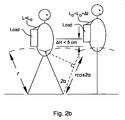
- Figure 2a illustrates that, while walking, a person's movement is like an inverted pendulum: one foot is put down, then the body vaults over it, then the back foot is brought forward and put down, and then the body vaults over that one.
- the load in a conventional backpack is tightly secured to the torso, the load must rise and fall about 5 cm as the person walks, resulting in large changes in mechanical energy.
- Figure 2b illustrates the use of compliant shoulder straps by which the load can move with respect to the torso, thereby reducing the vertical movements of the pack and the amount of mechanical work that must be done to move it.
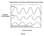
- Figure 3 illustrates how the suspended-load backpack allows for large movement of the load with respect to the frame and thereby reduces the vertical movement of the load with respect to the ground. This in turn leads to the reduction in forces on the shoulders of the wearer while running wearing the backpack of the invention.
- Figure 4 illustrates a rear perspective view of a first embodiment of a suspended-load backpack in accordance with the invention.
- Figure 5 illustrates a rear view of the suspended-load backpack of Figure 4 without the load.
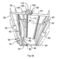
- Figure 6a illustrates a first embodiment of a mechanism for transferring mechanical movement to an electric motor using a lever.
- Figure 6b illustrates the mechanism of Figure 6a bent back to permit the user to hand crank the motor.
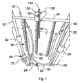
- Figure 7 illustrates a second embodiment of a mechanism for transferring mechanical movement to an electric motor using a rack and pinion.
- FIG. 8a illustrates the motor gears in more detail.
- Figure 8b illustrates the battery charger circuit
- Figure 9 illustrates the embodiment of Figure 7 where the springs are replaced with elastic straps.
- Figure 10 illustrates a third embodiment of a mechanism for transferring mechanical movement to an electric motor in a unidirectional manner using two rack and pinion systems, one for upward movement and one for downward movement.
- Figure 11 illustrates an alternate embodiment of a suspended-load backpack in which the motor is replaced by a unidirectional generator including a cylinder with turbine-driven generators on the top and bottom for use in generating electrical energy.
- Figure 12 illustrates a suspended-load backpack which is not according to the invention in which electrical energy is generated by electroactive polymer (EAP) straps that connect the suspended load to the frame.
- EAP electroactive polymer
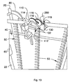
- Figure13 illustrates a suspended-load backpack which is not according to the invention in which a simple frictional device such as a fan is driven by the movement of the suspended load in an attempt to prevent resonance in the movement of the load during rapid movement.
- a simple frictional device such as a fan
- Figure 14 illustrates the embodiment of Figure 6 modified to include a friction adjustment device that allows the wearer to manually adjust the resistive torque generated by the motor.
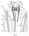
- Figure 15 illustrates the embodiment of Figure 7 modified to include a friction adjustment device that allows the wearer to manually adjust the resistive torque generated by the motor.
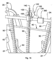
- Figure 16 illustrates the embodiment of Figure 7 modified to include a microprocessor that calculates the resistance across the motor on-the-fly and adjusts the resistance as desired to minimize excess movement of the backpack during rapid movement.
- Figure 17 illustrates a student backpack which is according to the invention whereby a container for the load is suspended by elastic straps from an internal frame.
- Figure 18 illustrates a rear perspective view of the backpack of Figure 17 .
- the inventor's analysis of humans walking with backpacks has yielded a possible mechanism for extracting mechanical energy.
- the large load in the backpack represents a significant problem for the subjects carrying it, the present inventor viewed the load in the backpack as an opportunity to harness mechanical energy and developed a way to extract some mechanical energy from the load's movement for eventual conversion to electricity.
- FIG. 4 A design of such a suspended-load backpack is illustrated in Figure 4 and is described in more detail below.
- the load in this backpack rides up and down on bushings constrained to vertical rods. Hence, the load is free to move in the vertical direction without danger of swaying.
- a lock is also provided to lock the load to the backpack frame to prevent it from moving (as when rock climbing).
- the backpack of Figure 4 enables electrical energy to be harvested while walking wearing the backpack. Depending on step frequency and hip excursion, 17-36 watts of energy may be required to raise and lower the load. Although it is difficult to extract the mechanical energy from the body's change in height of the center of mass, by interposing this device between the body and the load, some of the mechanical energy changes of the load can be captured.
- the present inventor has recognized that wearing the suspended-load pack of the invention reduces peak ground forces and more importantly, reduce forces on the shoulder ( Figure 3 ). This, in turn, should lead to a reduction in fatigue and orthopedic problems and may permit the wearer to carry greater loads. Further the reduction in force permits much faster movements, thereby making running with loads possible. The reasons for the reduced forces are believed to be the result of the fact that the load in the backpack exhibits controlled movement and does not move as far with respect to the ground.
- suspending the load in a compact package i.e., suspended-load backpack
- a compact package i.e., suspended-load backpack
- Suspension of the load permits generation of electricity for the purpose of powering devices in real time or charging batteries or capacitors for later use.
- Springs or an elastic sheet or cord with the appropriate spring constant are used to suspend the load compartment from the frame of the backpack. Electricity can be developed by driving an electric motor so that it becomes an electricity generator. The up-down movement of the load is transferred to the electric motor using either a lever or a rack and pinion to facilitate energy generation. The electric motor, in turn, produces current of alternating polarity that is rectified by a rectifying circuit with capacitive filtering. The output of the rectifying circuit provides charge to a battery charging unit mounted in or on the backpack.
- the electric motor also can be driven by hand by first disengaging the normal drive mechanism and either using the lever ( Figure 6b ) or a gear handle ( Figure 7 ) so that devices can be used (or batteries charged) when not walking with the backpack (either in inclement weather, at night, or under fire, as in military use).
- the motor may be replaced by electroactive polymers (EAPs), as appropriate, to generate electricity.
- EAPs electroactive polymers
- FIGS. 4 and 5 illustrate a rear perspective view of a first embodiment of a suspended-load backpack 10 in accordance with the invention.
- backpack 10 includes a frame 20 including vertical rods 22 and horizontal bars 24.
- rods 22 are made of hardened chrome plated shafts having 1 ⁇ 2 inch (12.5mm) diameters while bars 24 are made of aluminum.
- Frame 20 supports a suspended load 30 which may be in the form of a box or satchel connected to a load support structure or (e.g., aluminum) plate 40 suspended with respect to the frame 20.
- a load support structure e.g., aluminum
- the load support structure 40 is supported with respect to frame 20 in the vertical direction by extension springs 50 (e.g., nickel plated steel with 2:1 extension and 5.2 lbs/in. (0.588Nm) spring constant) that have spring constants selected to support the desired load rating for the suspended load 30.
- extension springs 50 e.g., nickel plated steel with 2:1 extension and 5.2 lbs/in. (0.588Nm) spring constant
- a fourth identical extension spring pulls down on plate 40, thereby providing a restoring force.
- three springs 50 are illustrated for connecting the load support structure 40 to the bar 24 of frame 20, those skilled in the art will appreciate that one or more springs 50 may be used to support the load 30.
- Load support structure is laterally stabilized with respect to frame 20 by a plurality of bushings 60 that ride up and down on rods 22.
- each bushing 60 comprises a self-aligning linear ball bearing with an inner diameter (e.g., 1 ⁇ 2 inch (12.5mm)) designed to ride upon rods 22.
- the combination of springs 50 and bushings 60 permits load support structure 40 and suspended load 30 to move up and down with respect to frame 20 as the wearer walks, without rubbing the wearer.
- a locking mechanism 70 may be included on one or both sides of the frame 20 to permit the wearer to lock the load support structure 40 (and hence load 30) in place to prevent movement, as when the wearer needs to move in a manner which does not allow for shifting of the load (e.g., rock climbing).
- Locking mechanism 70 may be a split block clamp with a locking knob.
- the locking mechanism 70 is made of a sufficiently strong material (e.g., PVC or nylon) to clamp the load support structure 40 to prevent movement.
- the frame 20 with the suspended load 30 and its support structure is worn by the user by inserting his/her arms through shoulder straps 80 and attaching waist belt 90.
- FIG. 6a illustrates the backpack of FIG. 4 and 5 with a first embodiment of a mechanism for transferring mechanical movement of the suspended load 30.
- the suspended load 30 moves up/down with load support structure 40 on bushings 60 as the wearer walks.
- Springs 50 have spring constants sufficient to permit controlled movements of the suspended load 30 and load support structure 40.
- the up/down movement of the load support structure 40 is transferred via a lever actuator structure 100 including lever handle control bars 102 to a lever 110 including lever pin or knob 112.
- lever handle control bars 102 crank the lever knob 112 up and down so as to crank gears that, in turn, crank the gears of a DC servo motor 120.
- DC servo motor 120 may be a GT-025 servo motor available from Dynetic Systems. This motor includes a 25:1 inline planetary gear head. As illustrated, the DC servo motor 120 is connected to bar 24 of frame 20 by a support plate 130. As illustrated in Figure 6b , the lever actuator structure 100 may fold away from the motor 120 and lever 110 to permit the wearer to access the lever 110. As a result, the wearer may crank the lever 110 to generate electricity when the backpack 10 is not being worn.
- Figure 7 illustrates a second embodiment of a mechanism for transferring mechanical movement to a DC servo motor 120 where the lever crank mechanism is replaced by a rack 140 connected to load support structure 40 and a corresponding pinion gear 150 connected directly or through gear linkages to DC servo motor 120.
- the rack 140 may fold away from the pinion gear 150 to facilitate access to the pinion gear 150 for manual cranking of the DC servo motor 120, as when the user is resting.
- Figure 8a illustrates the mechanism of Figure 7 in more detail. As illustrated, the up/down movement of the rack 140 with respect to the pinion gear 150 turns gears 114, 116, 118, and 119 so as to transfer energy to DC servo motor 120.
- the output of DC servo motor 120 is provided to an electronics charging unit 400 where it is rectified by a rectifier 122 and filtered by a capacitive filter 124 before being provided to a battery charger 126 for recharging batteries in battery pack 128 as well as electrical components, and the like.
- the springs in any of the embodiments may be replaced with elastic straps or cords (e.g. bungee cords) 160 having the appropriate tensile strength and elasticity.
- elastic straps or cords e.g. bungee cords
- Figure 10 illustrates a third embodiment of a mechanism for transferring mechanical movement to an electric motor unidirectionally using two racks 170 and 175 and two sets of pinion gears 180, 195 and 185, 190, one rack and pinion gear for upward movement (rack 175 and pinion gears 185, 190) and one rack and pinion gear for downward movement (rack 170 and pinion gears 180, 195).
- Better electricity generation may be achieved by providing unidirectional movement of the DC servo motor 120.
- the two racks 170 and 175, two pinion gears180 and 190, and two free wheels 205, 208 are attached to the motor gears ( Figure 8b ) to facilitate clockwise cranking of the motor gear both as the suspended load 30 rises and as suspended load 30 falls during walking.
- one rack 170 drives the motor gear on the way up and the other rack 175 drives the motor gear on the way down.
- this movement provides positive current with less fluctuation in voltage and obviates the need for a rectifier circuit.
- FIG 11 illustrates another implementation of a unidirectional generator involving using a cylinder 202 with turbine-driven generators 204 on the top and bottom.
- either the fan blades or the generator polarity would need to be opposite at top and bottom to permit positive current to be generated both when the piston 206 is moved up and down by load support structure 40.
- the piston 206 is moved up and down to turn the fans of generators 204 at the positive pressure end. Positive voltage is generated at both ends because the fans are cut with opposite blade directions.
- This also requires two one-way valves 211 and 213 at the respective ends.
- the one way valve 213 keeps air from moving over the bottom fan blade in the wrong direction (which would cause negative voltage).The air flow produced can be used to cool the operator.
- the generated electricity is output via leads 214, 215 as indicated.
- FIG 12 illustrates an alternate embodiment of a suspended-load backpack in which electrical energy is generated by electroactive polymer (EAP) straps 210 that connect the suspended load to the frame.
- EAP electroactive polymer
- the function of the springs 50 and DC servo motor 120 is replaced by "artificial muscles," such as electro-active polymers (EAPs) 210 of the type described by Pelrine et al., for example.
- EAPs 210 and other artificial muscles are elastic materials that can replace the springs 50.
- EAPs 210 have the special properties that they function like a variable capacitor that changes capacitance based on changes of their thickness and area.
- the associated power electronics circuit can be configured so that as the EAP 210 is deformed in a repetitive cycle by the mechanical work of the load, the power electronics can energize the EAP 210 and harvest electrical energy from it. As illustrated in Figure 12 , this electricity may be captured by electrodes 220 and forwarded via wires 230 to the power control circuitry 240 which extracts electrical energy from the outputs of the electrodes 220 of the EAPs 210 as described, for example, by Pelrine et al. in an article entitled "Dielectric elastomers: Generator mode fundamentals and applications," Proceedings of SPIE - The International Society for Optical Engineering, Vol. 4329,2001, pp. 148-156 ).
- EAPs 210 serve the function of an electrical generator as well as load suspension device, thereby obviating the need for the DC servo motor 120:
- EAPs 210 and other "artificial muscles" currently in development have several potential advantages.
- EAPs would be much lighter than the springs 50 and DC servo motor 120 required for conventional electrical generation. It is further recognized that to extract electrical energy efficiently the movement of the load will need to be "geared" to he optimal strain of the EAP 210. Accordingly, a mechanical transformer, as simple as a lever, may need to be used to accomplish this.
- the backpack described above has been found to generate an average electrical power of about 2W (peak is 10 W) when walking at 3.5 MPH (5.63 kmh) with a 40 lb (18.14kg) load.
- EAPs do not permit generation of this amount of power in part because of technical problems with electrodes and durability.
- the inventor contemplates that EAPs will soon develop to the extent that improved power levels will be obtained, thereby making the EAP embodiment of FIG. 12 more attractive for the extraction of electrical energy.
- Suspension of the load 30 in the backpack 10 reduces the vertical movements of the load 30 with respect to the ground.
- this permits load carriage to be more comfortable at moderate speeds and permits one to obtain faster load carriage speeds (i.e., one can run fast with a heavy pack), which is not possible (or far less stable) without load suspension.
- load carriage speeds i.e., one can run fast with a heavy pack
- the most basic way this can be achieved is by driving a simple frictional device with the lever or rack and pinion.
- FIG. 13 illustrates an arrangment in which a fan 250 is driven by the movement of the suspended load 30 in an attempt to prevent resonance in the movement of the load 30 during running.
- the backpack of FIG. 13 cools the wearer, prevents resonance movement of the load 30, thereby permitting controlled up and down movement, and reduces forces on the shoulders and the rest of the body of the wearer.
- FIG. 14 illustrates the embodiment of FIG. 6 modified to include a friction adjustment device (potentiometer) 265 that allows the wearer to adjust the resistive torque generated by the DC servo motor 120.
- a friction adjustment device potentiometer 265 that allows the wearer to adjust the resistive torque generated by the DC servo motor 120.
- Potentiometer 265 and/or different resistors in a switch box may provide differences in torques at a given speed for embodiments including a lever ( FIG. 14 ) or a rack ( FIG. 15 ) that can be adjusted for load and gait.
- a microprocessor 260 may be used that receives inputs from a tachometer (not shown) on the DC servo motor 120 as well as accelerometers on the pack frame 20 and load 30 (not shown). Using these inputs, the microprocessor 260 may calculate the best torque and change the load resistance across the DC servo motor 120 on-the-fly. This can be achieved by either the lever or rack & pinion system of FIGS. 14 and 15 , respectively.
- the generated electricity may be used to provide the power for the microprocessor 260, and hence a high level of ergonomic benefit free of battery power.
- adjusting the load resistance in this manner will have a damping effect and provide an opportunity to set the best damping of movement of the load with respect to the frame and/or the ground for a particular gait or speed.
- FIGS 17 and 18 show such an arrangement where a Kelty day pack which normally comes with two aluminum stays is fitted with additional stays across the top and the bottom to form a frame 270.
- clips or jam cleats (not shown) hold sheets of elastic material 290 that suspend a bag 280 within the pack 310. Clips or jam cleats are desired that permit the tension of the elastic material 290 to be adjusted according to the load.
- Heavy books (or other dense materials such as water) are inserted into this bag 280 and the suspension of the bag 280 reduces shoulder forces applied via shoulder straps 300 during walking for the same reasons as explained above. Suspension of the load in this manner also permits running with a sizable load that would otherwise be very difficult. It should be noted that with the development of artificial muscle technology, replacement of elastic sheeting with EAPs would permit electrical energy generation as well.
- Hybrid Device Electricity Generation While Minimizing Shoulder Strain
- the backpack 10 includes a frame 20 with a DC servo motor 120 driven by lever 110 ( Figure 6 ) or rack 140 and pinion gear 150 ( Figure 7 ) with an attached microprocessor 260 that calculates the appropriate load for the DC servo motor 120 to optimize ergonomic consideration and speed.
- this system also can generate electricity-certainly enough to power the microprocessor 260.
- the driven motor 120 (or EAPs 210) can both power electricity generation and reduce locomotion induced forces.
- the backpack of the invention is a hybrid device that utilizes motors or artificial muscles and allows the operator to decide what activity to optimize for (or somewhere in between) and hence adjust the system appropriately.
- the lock on the suspended load may be designed to engage automatically.
- the motor described herein may also be replaced by a single crystal 1-3 composite of the type described by Park et al. in “Ultrahigh strain and piezoelectric behavior in relaxor based ferroelectric single crystals", J. Appl. Phys. 82, 1804 (1997 ).or by PVDF devices of the type described by Xia et al. in "High Electromechanical Responses in Terpolymer of Poly(vinylidene fluoride trifluoroethylene- chlorofluoroethylene” Adv. Maters. Vol. 14, p. 1574 (2002 ), that can be used to generate electricity when pulled or stretched by the load attached thereto. Accordingly, the scope of the invention is not intended to be limited to the preferred embodiment described above, but only by the appended claims.
Landscapes
- Engineering & Computer Science (AREA)
- Chemical & Material Sciences (AREA)
- Combustion & Propulsion (AREA)
- Health & Medical Sciences (AREA)
- Toxicology (AREA)
- Mechanical Engineering (AREA)
- General Engineering & Computer Science (AREA)
- Manipulator (AREA)
- Rehabilitation Tools (AREA)
- Portable Outdoor Equipment (AREA)
Description
- The present invention relates to ergonomically designed backpacks and, in particular, to backpacks that permit the wearer to generate electrical energy from the mechanical energy created by movement of the backpack during walking.
- Man has become more dependent on technology in all arenas of life. The ubiquitous use of mobile technologies requires that constant electrical power, presently provided by batteries, is available. Total dependence on batteries is problematic because short battery lifespan requires larger batteries, and battery weight can become a significant issue. In the case of the military, carrying batteries becomes a backbreaking load (packs weigh in excess of 80 lbs) which limits the time soldiers can remain in the field. A device that could generate significant electrical energy to recharge batteries while one is on the move, would provide greater freedom and operational ability.
- Energy "harvesting" from body movements requires the capture of mechanical energy and conversion into electrical energy. The key requirement for many electrical energy-generating technologies, such as electroactive polymers, is the ability to produce movement against a load (i.e., provide the mechanical work that will be converted to electrical energy). Up to now, attempts to extract such energy have been extremely limited in terms of wattage (i.e., 10-20 milliwatts). For example, a watch that stays powered by arm movements generates on the order of only a few thousandths of a watt or less. Because the work done by muscles during locomotion is generally inaccessible, most attempts at harvesting mechanical energy have focused on harvesting energy from shoes by, for example, placing piezoelectric devices in shoes. For example, Drake describes such a device in "The Greatest Shoe on Earth," Wired, February 2001, pp. 90-100. Unfortunately, the only place that is relatively accessible, the foot, is a relatively poor location for extracting mechanical energy because very little mechanical work is done at the foot during locomotion.
- More recently, Pelrine et al. suggested in published
U.S. Patent Application No. 2001/0035723 that electroactive polymer devices could be used to generate electrical energy by converting mechanical energy generated during by heel strikes during walking into electrical energy. Pelrine et al. also suggested that such polymer devices may be used to convert the up and down motion of a backpack into electrical energy. However, Pelrine et al. offer no suggestions as to how to design such a backpack device. Pelrine et al. also do not recognize that a suspended load leads to controlled up/down movement and reduced stress on the wearer's shoulders as well as on the rest of his or her body. - Accordingly, there remains a strong need to develop a device capable of harvesting energy on the order of watts, particularly for military applications.
- Heavy backpack loads are known to lead to spinal injuries, particularly in children. Many school districts encourage parents to purchase spare sets of books for their children to minimize the weight of backpack loads. Of course, this approach is quite expensive. Recently, wheels have been added to backpacks so that the backpacks may be pulled along the ground, thereby reducing the load on the user's back. Such designs are problematic since they do not provide much assistance when the user has to cross grass or more difficult terrain. An improved way to reduce load on the wearer's back is desired.
- Another recent approach to the problem of heavy backpacks is suggested by Duckworth in
U.S. Patent No. 6,619,523 , whereby a shock absorber system is applied to the backpack to take the jolts out of hitting the ground. In particular, a damper (air piston) is added to the frame of the backpack to reduce the movements of the load with respect to the pack frame. Unfortunately, Duckworth did not address the physics of walking or running with a backpack and simply built classic shock absorbers. Their springs are too short in length and too stiff to permit the large relative movements between the frame and the load which are necessary to keep the load relatively still with respect to the ground. Accordingly, rapid movement with the backpack taught by Duckworth would cause the generation of a very large force which would limit the relative movement between the load and the frame resulting in high shoulder loading as well as potentially causing the wearer to lose his or her balance. - Accordingly, there remains a strong need to develop a device capable of minimizing load stresses on the shoulders on the wearer of a conventional backpack. The present invention is designed to address these needs in the art.
- Based on a biomechanical analysis, the present inventor has developed a strategy and device (suspended-load backpack) that can produce large forceful movements. These movements, when coupled with artificial muscle energy-generating or other mechanical energy to electrical energy conversion technologies in accordance with the invention permit the generation of several watts of electrical energy during normal walking movements. The backpack is designed to permit the load to move relative to the backpack frame during walking so that the large movements between the load and the frame of the backpack during walking can be transferred to a motor through, for example, a rack and pinion gear, to convert the mechanical movement to electrical energy. The movement may also be converted to electrical energy by using an electroactive polymer (EAP) (or other artificial muscle technologies) to connect the suspended load to the frame. These large movements of the load also reduce the absolute vertical motion of the load with respect to the ground. In particular, because the hip (and thus the pack frame) go up a down a good deal during walking (and even more during running) with a fixed load, large accelerations are necessary that exert large forces back on the shoulders and other parts of the body. The large relative movement between the frame and the load noted above reduces the absolute vertical excursion of the load and thus the locomotion induced increase in force. To facilitate this function, such designs not only allow the load to make large movements but to move in a controlled fashion. This prevents the wearer from losing his or her balance as the load moves up and down along the backpack frame, and extends human performance by permitting the wearer to run with heavy loads.
- The above and other objects and advantages will become apparent to one skilled in the art based on the following detailed description of the invention, of which:
-
Figure 1 illustrates the average running speed maintained over time of event for world records, illustrating how running performance drops as the duration of the event increases. -
Figure 2a illustrates that, while walking, a person's movement is like an inverted pendulum: one foot is put down, then the body vaults over it, then the back foot is brought forward and put down, and then the body vaults over that one. As the load in a conventional backpack is tightly secured to the torso, the load must rise and fall about 5 cm as the person walks, resulting in large changes in mechanical energy. -
Figure 2b illustrates the use of compliant shoulder straps by which the load can move with respect to the torso, thereby reducing the vertical movements of the pack and the amount of mechanical work that must be done to move it. -
Figure 3 illustrates how the suspended-load backpack allows for large movement of the load with respect to the frame and thereby reduces the vertical movement of the load with respect to the ground. This in turn leads to the reduction in forces on the shoulders of the wearer while running wearing the backpack of the invention. -
Figure 4 illustrates a rear perspective view of a first embodiment of a suspended-load backpack in accordance with the invention. -
Figure 5 illustrates a rear view of the suspended-load backpack ofFigure 4 without the load. -
Figure 6a illustrates a first embodiment of a mechanism for transferring mechanical movement to an electric motor using a lever. -
Figure 6b illustrates the mechanism ofFigure 6a bent back to permit the user to hand crank the motor. -
Figure 7 illustrates a second embodiment of a mechanism for transferring mechanical movement to an electric motor using a rack and pinion. -
Figure 8a illustrates the motor gears in more detail. -
Figure 8b illustrates the battery charger circuit. -
Figure 9 illustrates the embodiment ofFigure 7 where the springs are replaced with elastic straps. -
Figure 10 illustrates a third embodiment of a mechanism for transferring mechanical movement to an electric motor in a unidirectional manner using two rack and pinion systems, one for upward movement and one for downward movement. -
Figure 11 illustrates an alternate embodiment of a suspended-load backpack in which the motor is replaced by a unidirectional generator including a cylinder with turbine-driven generators on the top and bottom for use in generating electrical energy. -
Figure 12 illustrates a suspended-load backpack which is not according to the invention in which electrical energy is generated by electroactive polymer (EAP) straps that connect the suspended load to the frame. -
Figure13 illustrates a suspended-load backpack which is not according to the invention in which a simple frictional device such as a fan is driven by the movement of the suspended load in an attempt to prevent resonance in the movement of the load during rapid movement. -
Figure 14 illustrates the embodiment ofFigure 6 modified to include a friction adjustment device that allows the wearer to manually adjust the resistive torque generated by the motor. -
Figure 15 illustrates the embodiment ofFigure 7 modified to include a friction adjustment device that allows the wearer to manually adjust the resistive torque generated by the motor. -
Figure 16 illustrates the embodiment ofFigure 7 modified to include a microprocessor that calculates the resistance across the motor on-the-fly and adjusts the resistance as desired to minimize excess movement of the backpack during rapid movement. -
Figure 17 illustrates a student backpack which is according to the invention whereby a container for the load is suspended by elastic straps from an internal frame. -
Figure 18 illustrates a rear perspective view of the backpack ofFigure 17 . - A detailed description of illustrative embodiments of the present invention will now be described with reference to
Figures 1-18 . Although this description provides detailed examples of possible implementations of the present invention, it should be noted that these details are intended to be exemplary and in no way delimit the scope of the invention. - The inventor's analysis of humans walking with backpacks has yielded a possible mechanism for extracting mechanical energy. Although the large load in the backpack represents a significant problem for the subjects carrying it, the present inventor viewed the load in the backpack as an opportunity to harness mechanical energy and developed a way to extract some mechanical energy from the load's movement for eventual conversion to electricity.
- As mentioned above, while walking, a person's movement is like an inverted pendulum: one foot is put down and then vaults over it causing the hip to cycle up and down 4-5 cm. Any object rigidly attached to the body also has to move up and down. Thus, if one is carrying a load in a backpack, because it is fixed to the body it has to go up and down that same vertical distance (
Figure 2a ). A considerable amount of mechanical work is done if the load is heavy. In the case of an 80lb load (36 kg), for example, 18 J of energy accompanies each step assuming a 5 cm displacement. This mechanical energy is also inaccessible if the load is rigidly attached to the body. The goal of the inventor, therefore, was to decouple the movement of the load with respect to the body so that the differential movement created between the load and the body could be used to drive electrical generation technology that converts the mechanical movement into electrical energy. - The simplest approach is the use of compliant shoulder straps as shown in
Figure 2b . However, the differential movement might cause the backpack to rub on the hips, back and shoulders of the wearer and thus cause discomfort. Also, the friction will prevent the backpack from moving through the full range of movement (i.e., <5 cm). An alternate solution is proposed in accordance with the invention whereby the pack frame is fixed to the body as in a normal pack, but instead of fixing the load to the pack frame, the load is suspended from the frame so that the load would still be decoupled from the body. As illustrated inFigure 3 and described in more detail below, the movement of the load with respect to the frame reduces vertical excursion of the load with respect to the ground and in turn reduces the forces on the wearer's shoulders. A design of such a suspended-load backpack is illustrated inFigure 4 and is described in more detail below. During walking, the load in this backpack rides up and down on bushings constrained to vertical rods. Hence, the load is free to move in the vertical direction without danger of swaying. As desired, a lock is also provided to lock the load to the backpack frame to prevent it from moving (as when rock climbing). - The backpack of
Figure 4 enables electrical energy to be harvested while walking wearing the backpack. Depending on step frequency and hip excursion, 17-36 watts of energy may be required to raise and lower the load. Although it is difficult to extract the mechanical energy from the body's change in height of the center of mass, by interposing this device between the body and the load, some of the mechanical energy changes of the load can be captured. - The present inventor has recognized that wearing the suspended-load pack of the invention reduces peak ground forces and more importantly, reduce forces on the shoulder (
Figure 3 ). This, in turn, should lead to a reduction in fatigue and orthopedic problems and may permit the wearer to carry greater loads. Further the reduction in force permits much faster movements, thereby making running with loads possible. The reasons for the reduced forces are believed to be the result of the fact that the load in the backpack exhibits controlled movement and does not move as far with respect to the ground. - One usually considers a load only in terms of the force required while standing still. This considerably underestimates the problem. As mentioned above, when one walks or runs, the hips rise and fall, and if the load is rigidly attached to the body, the load has to undergo the same change in height, as illustrated in
Figure 2a . This requires that the load be accelerated upwards on the up-step and hence more force be exerted up on the load. As most loads are carried on the shoulder, this increases the force and pressure on the shoulder. This added pressure can be very large. For instance, Kram, in an article entitled "Carrying Loads With Springy Poles," Journal of Applied Physiology, Vol. 71(3), pp. 1119-22 (1991), found that when people run with a weight attached to their shoulders that the peak force on the shoulders is approximately 2-fold higher than the static weight when the person is standing still. As noted by Kram, merchants in Asia often carry loads at the end of long bamboo pools carried over their shoulders. By hanging the loads from springy poles, it was found that as experimental subjects run, the load stays close to the ground and does not undergo the large vertical excursions observed for the center of mass of the person (SeeFigure 2 ). Because it is not necessary to accelerate the load upwards on the up-step, the forces that are generated at the feet and shoulders do not have to increase above that necessary to support the static weight while standing still. - Hence, two important facts are clear: 1) Movement causes the dynamic forces on the shoulders to be much larger than the static forces when standing still. Hence, dynamic forces during walking or running are likely to be an important determinant of orthopedic problems. 2) Suspending the load can reduce the dynamic forces on the shoulders down to the level of the static forces when standing still (i.e., the weight), and hence may be an important avenue for reducing orthopedic injury.
- Clearly, any intervention that reduces dynamic force on the shoulders of adults has considerable importance for recreational backpackers and especially the military where load carriage is recognized as a major problem. Likewise as we become increasingly technology-dependent, there is a greater need for carrying laptop computers and even medical devices. Reducing the dynamic forces on the shoulders of the general public, and especially in the elderly, is of considerable interest, as well.
- The suspension of backpack loads also represents a potential opportunity to reduce the dynamic loads experienced by school children who carry heavy backpacks. There is significant evidence from numerous studies around the world indicating that children carrying heavy backpacks is a considerable problem and may have potential long-term medical consequences. Back pain is a relatively common symptom among school children and in many the pain is recurrent or chronic even before puberty. Studies by Negrini et al. and reported in "Backpacks On! Schoolchildren's Perception of Load, Associations With Back Pain and Factors Determining the Load," Spine, Vol. 27(2), pp. 187-195, 2002, have shown that school backpacks are felt to be heavy by 79% of children, to cause fatigue by 65.7%, and to cause back pain by 46.1%. In addition, numerous studies have shown that in children, carrying weight in excess of 15% of one's body mass (which they almost always do), can lead to significant increase in trunk inclination, abnormal standing posture while carrying the load, as well as muscle soreness, back pain, numbness, shoulder pain, and even spinal deformities.
- Based on the forgoing explanation of the physics of load carrying with poles and the physical problems found in children, suspending the load in a compact package (i.e., suspended-load backpack) represents an important contribution to solving this problem.
- Suspension of the load permits generation of electricity for the purpose of powering devices in real time or charging batteries or capacitors for later use. Springs or an elastic sheet or cord with the appropriate spring constant are used to suspend the load compartment from the frame of the backpack. Electricity can be developed by driving an electric motor so that it becomes an electricity generator. The up-down movement of the load is transferred to the electric motor using either a lever or a rack and pinion to facilitate energy generation. The electric motor, in turn, produces current of alternating polarity that is rectified by a rectifying circuit with capacitive filtering. The output of the rectifying circuit provides charge to a battery charging unit mounted in or on the backpack. The electric motor also can be driven by hand by first disengaging the normal drive mechanism and either using the lever (
Figure 6b ) or a gear handle (Figure 7 ) so that devices can be used (or batteries charged) when not walking with the backpack (either in inclement weather, at night, or under fire, as in military use). As will be explained below, the motor may be replaced by electroactive polymers (EAPs), as appropriate, to generate electricity. -
FIGS. 4 and5 illustrate a rear perspective view of a first embodiment of a suspended-load backpack 10 in accordance with the invention. As illustrated,backpack 10 includes aframe 20 includingvertical rods 22 andhorizontal bars 24. In an illustrative embodiment,rods 22 are made of hardened chrome plated shafts having ½ inch (12.5mm) diameters whilebars 24 are made of aluminum.Frame 20 supports a suspendedload 30 which may be in the form of a box or satchel connected to a load support structure or (e.g., aluminum)plate 40 suspended with respect to theframe 20. In the embodiment ofFIGS. 4 and5 , theload support structure 40 is supported with respect to frame 20 in the vertical direction by extension springs 50 (e.g., nickel plated steel with 2:1 extension and 5.2 lbs/in. (0.588Nm) spring constant) that have spring constants selected to support the desired load rating for the suspendedload 30. A fourth identical extension spring pulls down onplate 40, thereby providing a restoring force. Although threesprings 50 are illustrated for connecting theload support structure 40 to thebar 24 offrame 20, those skilled in the art will appreciate that one ormore springs 50 may be used to support theload 30. Load support structure is laterally stabilized with respect to frame 20 by a plurality ofbushings 60 that ride up and down onrods 22. In an illustrative embodiment, fourbushings 60 are provided (one on each corner of the load support structure 40) for stability, and eachbushing 60 comprises a self-aligning linear ball bearing with an inner diameter (e.g., ½ inch (12.5mm)) designed to ride uponrods 22. The combination ofsprings 50 andbushings 60 permits loadsupport structure 40 and suspendedload 30 to move up and down with respect to frame 20 as the wearer walks, without rubbing the wearer. - As illustrated in
FIGS. 4 and5 , alocking mechanism 70 may be included on one or both sides of theframe 20 to permit the wearer to lock the load support structure 40 (and hence load 30) in place to prevent movement, as when the wearer needs to move in a manner which does not allow for shifting of the load (e.g., rock climbing). Lockingmechanism 70 may be a split block clamp with a locking knob. Preferably, thelocking mechanism 70 is made of a sufficiently strong material (e.g., PVC or nylon) to clamp theload support structure 40 to prevent movement. As illustrated, theframe 20 with the suspendedload 30 and its support structure is worn by the user by inserting his/her arms throughshoulder straps 80 and attachingwaist belt 90. -
FIG. 6a illustrates the backpack ofFIG. 4 and5 with a first embodiment of a mechanism for transferring mechanical movement of the suspendedload 30. As noted above, the suspendedload 30 moves up/down withload support structure 40 onbushings 60 as the wearer walks.Springs 50 have spring constants sufficient to permit controlled movements of the suspendedload 30 andload support structure 40. In the embodiment ofFIG. 6a , the up/down movement of theload support structure 40 is transferred via alever actuator structure 100 including leverhandle control bars 102 to alever 110 including lever pin orknob 112. In particular, as the load support structure moves up and down, leverhandle control bars 102 crank thelever knob 112 up and down so as to crank gears that, in turn, crank the gears of aDC servo motor 120. In an illustrative embodiment,DC servo motor 120 may be a GT-025 servo motor available from Dynetic Systems. This motor includes a 25:1 inline planetary gear head. As illustrated, theDC servo motor 120 is connected to bar 24 offrame 20 by asupport plate 130. As illustrated inFigure 6b , thelever actuator structure 100 may fold away from themotor 120 andlever 110 to permit the wearer to access thelever 110. As a result, the wearer may crank thelever 110 to generate electricity when thebackpack 10 is not being worn. -
Figure 7 illustrates a second embodiment of a mechanism for transferring mechanical movement to aDC servo motor 120 where the lever crank mechanism is replaced by arack 140 connected to loadsupport structure 40 and acorresponding pinion gear 150 connected directly or through gear linkages toDC servo motor 120. As in the embodiment ofFigure 6a , therack 140 may fold away from thepinion gear 150 to facilitate access to thepinion gear 150 for manual cranking of theDC servo motor 120, as when the user is resting.Figure 8a illustrates the mechanism ofFigure 7 in more detail. As illustrated, the up/down movement of therack 140 with respect to thepinion gear 150 turnsgears DC servo motor 120. As shown inFigure 8b , the output ofDC servo motor 120 is provided to anelectronics charging unit 400 where it is rectified by arectifier 122 and filtered by acapacitive filter 124 before being provided to abattery charger 126 for recharging batteries inbattery pack 128 as well as electrical components, and the like. - As illustrated in
Figure 9 , the springs in any of the embodiments may be replaced with elastic straps or cords (e.g. bungee cords) 160 having the appropriate tensile strength and elasticity. -
Figure 10 illustrates a third embodiment of a mechanism for transferring mechanical movement to an electric motor unidirectionally using tworacks rack 175 and pinion gears 185, 190) and one rack and pinion gear for downward movement (rack 170 and pinion gears 180, 195). Better electricity generation may be achieved by providing unidirectional movement of theDC servo motor 120. As illustrated, the tworacks free wheels 205, 208 (with opposite polarities) are attached to the motor gears (Figure 8b ) to facilitate clockwise cranking of the motor gear both as the suspendedload 30 rises and as suspendedload 30 falls during walking. As illustrated, onerack 170 drives the motor gear on the way up and theother rack 175 drives the motor gear on the way down. When coupled to afly wheel 200 to drive the motor gear in one constant direction, this movement provides positive current with less fluctuation in voltage and obviates the need for a rectifier circuit. -
Figure 11 illustrates another implementation of a unidirectional generator involving using acylinder 202 with turbine-drivengenerators 204 on the top and bottom. In the illustrated embodiment, either the fan blades or the generator polarity would need to be opposite at top and bottom to permit positive current to be generated both when thepiston 206 is moved up and down byload support structure 40. During use, as theinput rod 209 connected to theload support structure 40 moves up and down, thepiston 206 is moved up and down to turn the fans ofgenerators 204 at the positive pressure end. Positive voltage is generated at both ends because the fans are cut with opposite blade directions. This also requires two one-way valves piston 206 moves up, air comes in behind it from the oneway valve 213 at the bottom. The oneway valve 213 keeps air from moving over the bottom fan blade in the wrong direction (which would cause negative voltage).The air flow produced can be used to cool the operator. The generated electricity is output vialeads -
Figure 12 illustrates an alternate embodiment of a suspended-load backpack in which electrical energy is generated by electroactive polymer (EAP) straps 210 that connect the suspended load to the frame. In this embodiment, the function of thesprings 50 andDC servo motor 120 is replaced by "artificial muscles," such as electro-active polymers (EAPs) 210 of the type described by Pelrine et al., for example.EAPs 210 and other artificial muscles are elastic materials that can replace thesprings 50.EAPs 210 have the special properties that they function like a variable capacitor that changes capacitance based on changes of their thickness and area. Hence, the associated power electronics circuit can be configured so that as theEAP 210 is deformed in a repetitive cycle by the mechanical work of the load, the power electronics can energize theEAP 210 and harvest electrical energy from it. As illustrated inFigure 12 , this electricity may be captured byelectrodes 220 and forwarded viawires 230 to thepower control circuitry 240 which extracts electrical energy from the outputs of theelectrodes 220 of theEAPs 210 as described, for example, by Pelrine et al. in an article entitled "Dielectric elastomers: Generator mode fundamentals and applications," Proceedings of SPIE - The International Society for Optical Engineering, Vol. 4329,2001, pp. 148-156). Hence,EAPs 210 serve the function of an electrical generator as well as load suspension device, thereby obviating the need for the DC servo motor 120: -
EAPs 210 and other "artificial muscles" currently in development have several potential advantages. First, all of the mechanical energy extracted during relative movement of theload 30 will be stored in theEAP 210, thus avoiding frictional losses in gears of an electromagnetic system. Second, much higher efficiencies of conversion of mechanical energy to electrical energy is offered byEAP 210 than by conventional motors where losses are considerable. Third, as noted by Pelrine et al., the energy density ofEAPs 210 are very high compared to electromagnetic technology (i.e., at least an order of magnitude higher). Moreover, EAPs would be much lighter than thesprings 50 andDC servo motor 120 required for conventional electrical generation. It is further recognized that to extract electrical energy efficiently the movement of the load will need to be "geared" to he optimal strain of theEAP 210. Accordingly, a mechanical transformer, as simple as a lever, may need to be used to accomplish this. - The backpack described above has been found to generate an average electrical power of about 2W (peak is 10 W) when walking at 3.5 MPH (5.63 kmh) with a 40 lb (18.14kg) load. At present, EAPs do not permit generation of this amount of power in part because of technical problems with electrodes and durability. However, the inventor contemplates that EAPs will soon develop to the extent that improved power levels will be obtained, thereby making the EAP embodiment of
FIG. 12 more attractive for the extraction of electrical energy. - Suspension of the
load 30 in thebackpack 10 reduces the vertical movements of theload 30 with respect to the ground. As noted above with respect toFIG. 3 , this permits load carriage to be more comfortable at moderate speeds and permits one to obtain faster load carriage speeds (i.e., one can run fast with a heavy pack), which is not possible (or far less stable) without load suspension. While it is possible to walk with just thesprings 50 attached to theload 30, as one runs a resonance will be achieved and the movement of the load will become too large and difficult to control. Hence, some energy has to be removed from the system to prevent resonance. The most basic way this can be achieved is by driving a simple frictional device with the lever or rack and pinion. Although any frictional device would work, a particularly attractive one is a fan because the air circulated by the fan can provide cooling to the individual carrying the pack.FIG. 13 illustrates an arrangment in which afan 250 is driven by the movement of the suspendedload 30 in an attempt to prevent resonance in the movement of theload 30 during running. Thus, the backpack ofFIG. 13 cools the wearer, prevents resonance movement of theload 30, thereby permitting controlled up and down movement, and reduces forces on the shoulders and the rest of the body of the wearer. - The benefit of preventing such resonance movement of the load 30 (i.e., permitting controlled up and down movement) was proven experimentally by filling a
backpack 10 of the embodiment ofFIG. 6 with a 40 lb (18.14kg) load (total weight is 50 lb (22.68kg)) and having the wearer run on a treadmill (seeFIG. 3 ). When theload 30 was free to move up and down on theframe 20 with some damping of the movement with respect to the frame to control resonance, the wearer was able to run comfortably in excess of 6 miles an hour (9.66kmh). Theload 30 was then clamped so that it would not move up and down on theframe 20. The wearer was unable to continue running comfortably and would go wildly out of control. Thus, the invention permits one to run with large loads, which is simply not possible otherwise. The invention thus has obvious implications for the military as well as athletic training. - A more sophisticated system includes a frictional device whose friction can be easily adjusted. For example,
FIG. 14 illustrates the embodiment ofFIG. 6 modified to include a friction adjustment device (potentiometer) 265 that allows the wearer to adjust the resistive torque generated by theDC servo motor 120. As known by those skilled in the art, one may alter the resistive torque generated by theDC servo motor 120 by altering the resistance value ofpotentiometer 265 across the output of theDC servo motor 120.Potentiometer 265 and/or different resistors in a switch box may provide differences in torques at a given speed for embodiments including a lever (FIG. 14 ) or a rack (FIG. 15 ) that can be adjusted for load and gait. It may be found, however, that to optimize load suspension (in theory one would want the load to stay at the same vertical height throughout the step cycle), it may be necessary to actively control the torque during the step. For this to be accomplished, a microprocessor 260 (FIG. 16 ) may be used that receives inputs from a tachometer (not shown) on theDC servo motor 120 as well as accelerometers on thepack frame 20 and load 30 (not shown). Using these inputs, themicroprocessor 260 may calculate the best torque and change the load resistance across theDC servo motor 120 on-the-fly. This can be achieved by either the lever or rack & pinion system ofFIGS. 14 and15 , respectively. Of course, since electricity is being generated, the generated electricity may be used to provide the power for themicroprocessor 260, and hence a high level of ergonomic benefit free of battery power. Also, adjusting the load resistance in this manner will have a damping effect and provide an opportunity to set the best damping of movement of the load with respect to the frame and/or the ground for a particular gait or speed. - It is not necessary for the backpack to have a large external frame as illustrated in the above backpacks. Rather, the ergonomic advantages can be provided to day packs or student book bags as well, particularly those fitted with an light weight internal frame.
Figures 17 and18 show such an arrangement where a Kelty day pack which normally comes with two aluminum stays is fitted with additional stays across the top and the bottom to form aframe 270. In this configuration, clips or jam cleats (not shown) hold sheets ofelastic material 290 that suspend abag 280 within thepack 310. Clips or jam cleats are desired that permit the tension of theelastic material 290 to be adjusted according to the load. Heavy books (or other dense materials such as water) are inserted into thisbag 280 and the suspension of thebag 280 reduces shoulder forces applied viashoulder straps 300 during walking for the same reasons as explained above. Suspension of the load in this manner also permits running with a sizable load that would otherwise be very difficult. It should be noted that with the development of artificial muscle technology, replacement of elastic sheeting with EAPs would permit electrical energy generation as well. - Many of the embodiments of backpacks for generating electricity set forth above have the same configurations as those for improving ergonomics. However, because the goals differed, the control equipment would be optimized for each particular function. For instance, in the embodiment of
Figure 16 , thebackpack 10 includes aframe 20 with aDC servo motor 120 driven by lever 110 (Figure 6 ) orrack 140 and pinion gear 150 (Figure 7 ) with an attachedmicroprocessor 260 that calculates the appropriate load for theDC servo motor 120 to optimize ergonomic consideration and speed. As noted above, this system also can generate electricity-certainly enough to power themicroprocessor 260. The basic point is that the driven motor 120 (or EAPs 210) can both power electricity generation and reduce locomotion induced forces. To an extent these two functions are compatible-i.e., when running or walking fast with the backpack, mechanical energy must be removed from the system to prevent resonance. At the same time, this mechanical energy can be converted to electrical energy providing benefit for both functions. While if one were to optimize the system for electricity generation, it may be somewhat non-optimal for reduction in locomotive induced force, and vice-a versa, under microprocessor control one may tune the system for electricity generation or for ergonomic considerations depending on what is most important to the operator. Hence, in a preferred embodiment, the backpack of the invention is a hybrid device that utilizes motors or artificial muscles and allows the operator to decide what activity to optimize for (or somewhere in between) and hence adjust the system appropriately. - Those skilled in the art will also appreciate that numerous other modifications to the invention are possible within the scope of the invention. For example, if load shifting during rapid movements become a significant problem, the lock on the suspended load may be designed to engage automatically. Also, the motor described herein may also be replaced by a single crystal 1-3 composite of the type described by Park et al. in "Ultrahigh strain and piezoelectric behavior in relaxor based ferroelectric single crystals", J. Appl. Phys. 82, 1804 (1997).or by PVDF devices of the type described by Xia et al. in "High Electromechanical Responses in Terpolymer of Poly(vinylidene fluoride trifluoroethylene- chlorofluoroethylene" Adv. Maters. Vol. 14, p. 1574 (2002), that can be used to generate electricity when pulled or stretched by the load attached thereto. Accordingly, the scope of the invention is not intended to be limited to the preferred embodiment described above, but only by the appended claims.
Claims (22)
- A suspended load backpack (10), comprising:a frame (20) that moves up and down with the gait of a wearer of the backpack;shoulder straps (80) attached to the frame ;a load storage bag (30) for accepting a load to be carried by said backpack, the load storage bag (30) being connected to the frame to permit movement of the load and load storage bag relative to the frame;at least one elastic element (50) that suspends the load storage bag from the frame, the elastic element being suitably dimensioned and having elastic characteristics permitting the load storage bag and the load to move up and down relative to the frame in accordance with a gait of a wearer of the backpack, characterized in that, the backpack further comprises an energy conversion device (120) that converts up and down movement of the load storage bag and the load into electrical energy.
- A suspended load backpack as in claim 1, further comprising an outer shell (310) that surrounds at least said load storage bag.
- A suspended load backpack as in claim 1, wherein said at least one elastic element connects the load storage bag to a top and a bottom portion (24) of said frame.
- A suspended load backpack as in claim 1, wherein said at least one elastic element is one of a spring or an elastic strap.
- A suspended load backpack as in claim 1, further comprising a support plate (130) connected to said load storage bag, said support plate being connected to the frame by said at least one elastic element.
- A suspended load backpack as in claim 5, wherein said frame has at least two vertical rods (22), further comprising bushings (60) on each of said vertical rods, said bushings being connected to said support plate on opposite sides of said support plate and adapted to move up and down on said vertical rods with up and down movement of said load storage bag and said support plate.
- A suspended load backpack as in claim 6, further comprising at least one locking device (70) connected to at least one of said vertical rods and adapted to prevent said support plate from moving with respect to said frame when said locking device is tightened.
- A suspended load backpack as in claim 1, further comprising a lever actuator (100) adapted to move up and down with the load storage bag relative to the frame.
- A suspended load backpack as in claim 8, further comprising a lever connected to gears and adapted to turn said gears in response to up and down movement imparted to said lever by said lever actuator as the load storage bag moves up and down.
- A suspended load backpack as in claim 9, wherein said lever actuator is adjustable to be moved away from said lever to permit said gears to be accessed for manual cranking.
- A suspended load backpack as in claim 1, further comprising a rack (140) adapted to move up and down with the load storage bag relative to the frame and a pinion gear (150) connected to said frame so as not to move up and down relative to the frame.
- A suspended load backpack as in claim 11, wherein said rack is adapted to cause said pinion gear to turn as said rack moves up and down with said load storage bag.
- A suspended load backpack as in claim 12, wherein said rack is adjustable to be moved away from said pinion gear to permit said pinion gear to be accessed for manual cranking.
- A suspended load backpack as in claim 11, further comprising another rack adapted to move up and down with the load storage bag relative to the frame and another pinion gear connected to said frame so as not to move up and down relative to the frame.
- A suspended load backpack as in claim 14, further comprising a gear (200) that engages with said pinion gear and said another pinion gear, said pinion gear rotating said gear in a first direction when said rack moves up with said load storage bag and said another pinion gear rotating said gear in said first direction when said another rack moves down with said load storage bag.
- A suspended load backpack as in claim 12, wherein the energy conversion device comprises a DC servo motor (120) mounted to said frame and responsive to said gear so as to turn gears within the DC servo motor, whereby turning of said gears within the DC servo motor results in the generation of electrical energy.
- A suspended load backpack as in claim 16, further comprising a manually controlled potentiometer (265) adapted to adjust a value of load resistance across an output of the DC servo motor.
- A suspended load backpack as in claim 16, further comprising a tachometer on the DC servo motor, an accelerometer on the frame, an accelerator on the load storage bag, and a microprocessor responsive to outputs of said tachometer and accelerometers to calculate a value for said load resistor on-the-fly as output values of said tachometer and accelerometers change.
- A suspended load backpack as in claim 1, further comprising a rod (209) adapted to move up and down with the load storage bag and a piston (206) mounted on the frame and responsive to up and down movement of said rod, said piston including a diaphragm that moves up and down with said rod within a cylinder (202) so as to drive turbine-driven generators (204) on the top and bottom of said cylinder.
- A suspended load backpack as in claim 19, wherein said turbine-driven generators each comprise fans with blade directions that are opposite to each other.
- A suspended load backpack (10), comprising:a frame (20) that moves up and down with the gait of a wearer of the backpack;shoulder straps (80) attached to the frame ;a load storage bag (30) for accepting a load to be carried by said backpack, the load storage bag (30) being connected to the frame to permit movement of the load and load storage bag relative to the frame;at least one elastic element (210) that suspends the load storage bag from the frame, the elastic element being suitably dimensioned and having elastic characteristics permitting the load storage bag and the load to move up and down relative to the frame in accordance with a gait of a wearer of the backpack, characterized in that said at least one elastic element comprises at least one electroactive polymer, EAP, strap (210) that converts up and down movement of the load storage bag and the load into electrical energy.
- A suspended load backpack as in claim 21, further comprising electrodes (220) on each of said EAP straps and power control circuitry responsive to outputs of said electrodes.
Applications Claiming Priority (2)
| Application Number | Priority Date | Filing Date | Title |
|---|---|---|---|
| US45547703P | 2003-03-17 | 2003-03-17 | |
| PCT/US2004/008081 WO2004082427A2 (en) | 2003-03-17 | 2004-03-17 | A backpack for harvesting electrical energy during walking and for minimizing shoulder strain |
Publications (3)
| Publication Number | Publication Date |
|---|---|
| EP1610646A2 EP1610646A2 (en) | 2006-01-04 |
| EP1610646A4 EP1610646A4 (en) | 2008-05-14 |
| EP1610646B1 true EP1610646B1 (en) | 2013-01-02 |
Family
ID=33030006
Family Applications (1)
| Application Number | Title | Priority Date | Filing Date |
|---|---|---|---|
| EP04757536A Expired - Lifetime EP1610646B1 (en) | 2003-03-17 | 2004-03-17 | A backpack for harvesting electrical energy during walking and for minimizing shoulder strain |
Country Status (4)
| Country | Link |
|---|---|
| US (2) | US6982497B2 (en) |
| EP (1) | EP1610646B1 (en) |
| CA (1) | CA2519138C (en) |
| WO (1) | WO2004082427A2 (en) |
Families Citing this family (103)
| Publication number | Priority date | Publication date | Assignee | Title |
|---|---|---|---|---|
| US7237524B2 (en) * | 2004-05-26 | 2007-07-03 | Sri International | Compliant walled combustion devices |
| WO2007016781A1 (en) | 2005-08-10 | 2007-02-15 | Simon Fraser University | Methods and apparatus for harvesting biomechanical energy |
| US7525203B1 (en) * | 2005-08-11 | 2009-04-28 | Jeffrey Racho | Back-up electric power generator for electronic components attached to automatic firearms |
| US7361999B2 (en) * | 2005-10-26 | 2008-04-22 | Ming-Hsiang Yeh | Body-carrying human power generation system |
| US7345407B2 (en) * | 2005-11-18 | 2008-03-18 | Adaptivenergy, Llc. | Human powered piezoelectric power generating device |
| US20080041644A1 (en) * | 2006-08-16 | 2008-02-21 | Tudek Arthur L | Electric shopping cart/burden carrier |
| DE102006049459A1 (en) * | 2006-10-17 | 2008-04-24 | Hexonia Gmbh | Body-worn active ventilation device |
| US8013457B2 (en) * | 2006-11-07 | 2011-09-06 | Potenco, Inc. | Human power generation using dual pulls |
| US20080150378A1 (en) * | 2006-11-07 | 2008-06-26 | Potenco, Inc. | Human power generation using a pulley |
| US7747355B2 (en) * | 2006-11-07 | 2010-06-29 | Potenco, Inc. | Electrical power generator with adaptive coupling |
| US8093731B2 (en) * | 2006-11-07 | 2012-01-10 | Potenco, Inc. | Gearless human power generation |
| US20080271683A1 (en) * | 2006-11-13 | 2008-11-06 | Lucy Mitchell | Retractable pet leash with self powered electric light |
| AU2007333874B2 (en) * | 2006-12-14 | 2013-07-18 | Lightning Packs Llc | Suspended load ergonomic backpack |
| US7605482B2 (en) * | 2007-01-08 | 2009-10-20 | Veryst Engineering Llc | Method and apparatus for energy harvesting using energy storage and release |
| US7847421B2 (en) * | 2007-01-19 | 2010-12-07 | Willowview Systems, Inc. | System for generating electrical energy from ambient motion |
| US7508085B2 (en) * | 2007-02-24 | 2009-03-24 | Phillip Reed Martineau | Flexible member energy conversion device |
| US7498682B2 (en) * | 2007-03-07 | 2009-03-03 | Aaron Patrick Lemieux | Electrical energy generator |
| US7851932B2 (en) * | 2007-03-29 | 2010-12-14 | Lightning Packs, Llc | Backpack based system for human electricity generation and use when off the electric grid |
| KR101128524B1 (en) * | 2007-05-18 | 2012-03-28 | 삼성전자주식회사 | Portable electronic device with electric generator |
| US7703562B2 (en) * | 2007-05-25 | 2010-04-27 | Toyota Motor Engineering & Manufacturing North America, Inc. | Energy efficient robotic system |
| DK1994840T3 (en) * | 2007-05-25 | 2018-06-18 | Hexonia Gmbh | Garment with a ventilation device. |
| US8076825B1 (en) | 2007-07-12 | 2011-12-13 | Louisiana Tech University Foundation, Inc. | Electret film generator |
| USD640195S1 (en) | 2007-07-20 | 2011-06-21 | Tremont Electric Incoporated | Personal mobile electrical energy generator |
| US20090174289A1 (en) * | 2007-12-28 | 2009-07-09 | Adaptivenergy Llc | Magnetic impulse energy harvesting device and method |
| US7977807B1 (en) | 2008-01-07 | 2011-07-12 | Medibotics Llc | Wearable device to generate electricity from human movement |
| WO2009091807A1 (en) * | 2008-01-14 | 2009-07-23 | Veryst Engineering Llc | Apparatus for in vivo energy harvesting |
| US8688224B2 (en) * | 2008-03-07 | 2014-04-01 | Tremont Electric, Inc. | Implantable biomedical device including an electrical energy generator |
| US7638889B2 (en) * | 2008-04-01 | 2009-12-29 | Ming-Hsiang Yeh | Bag/pack power generation device |
| US20090255969A1 (en) * | 2008-04-11 | 2009-10-15 | St. Francis Xavier University | Backpack having a suspended inner pouch |
| US8030786B2 (en) * | 2008-08-22 | 2011-10-04 | Willowview Systems, Inc. | System for generating electrical energy from ambient energy |
| US8120190B2 (en) * | 2008-09-29 | 2012-02-21 | Ncr Corporation | Shopping cart with a self-charging system |
| DE102008051184A1 (en) | 2008-10-14 | 2010-04-15 | Dynacc Gmbh | Body-worn protective device |
| US8464838B2 (en) * | 2009-01-26 | 2013-06-18 | Kenneth C. Brooks | System and method for generating mechanical movement |
| US20100187834A1 (en) * | 2009-01-27 | 2010-07-29 | Brooks Kenneth C | System and method for generating electrical energy |
| US8657169B2 (en) | 2009-04-24 | 2014-02-25 | Joan F. Demskey | Backpack |
| US9439501B2 (en) | 2009-04-24 | 2016-09-13 | Joan F. Demskey | Backpack |
| US8281970B2 (en) | 2009-04-24 | 2012-10-09 | Demskey Joan F | Backpack having a load compensating strap arrangement |
| US8998051B2 (en) | 2009-04-24 | 2015-04-07 | Joan F. Demskey | Backpack |
| US9167883B2 (en) | 2009-04-24 | 2015-10-27 | Joan F. Demskey | Backpack |
| US8350394B2 (en) * | 2009-09-30 | 2013-01-08 | Alcatel Lucent | Energy harvester apparatus having improved efficiency |
| WO2011053961A2 (en) | 2009-11-02 | 2011-05-05 | C & P Hiam Associates Llc | Stable backpack |
| US8525386B2 (en) * | 2009-12-09 | 2013-09-03 | Texas Instruments Incorporated | Dynamically adjustable orthotic device |
| WO2011085091A2 (en) * | 2010-01-06 | 2011-07-14 | Tremont Electric, Llc | Electrical energy generator |
| WO2011085093A2 (en) | 2010-01-06 | 2011-07-14 | Tremont Electric, Llc | Electrical energy generator |
| TWI469884B (en) * | 2010-05-17 | 2015-01-21 | Univ Nat Taiwan | Energy recovery design of two-way suspension system |
| US8723342B2 (en) | 2010-05-19 | 2014-05-13 | Robert Bosch Gmbh | Wearable generator device |
| US8564144B1 (en) | 2010-05-19 | 2013-10-22 | Lightning Packs, Llc | Light-weight human generated electricity |
| US8783537B2 (en) | 2010-07-28 | 2014-07-22 | Romina Ghassemi | Ergonomic backpack |
| CN102562498B (en) * | 2011-04-01 | 2014-07-16 | 胡锡文 | Hanging movement type power generation assembly and backpack comprising same |
| US9394876B2 (en) * | 2011-04-15 | 2016-07-19 | The Research Foundation For The State University Of New York | High-efficiency energy generator for harnessing mechanical vibration power |
| US8749081B2 (en) * | 2011-05-09 | 2014-06-10 | Phillip Reed Martineau | Moving fluid energy conversion device |
| US10307104B2 (en) | 2011-07-05 | 2019-06-04 | Saudi Arabian Oil Company | Chair pad system and associated, computer medium and computer-implemented methods for monitoring and improving health and productivity of employees |
| US10108783B2 (en) | 2011-07-05 | 2018-10-23 | Saudi Arabian Oil Company | Systems, computer medium and computer-implemented methods for monitoring health of employees using mobile devices |
| US9492120B2 (en) | 2011-07-05 | 2016-11-15 | Saudi Arabian Oil Company | Workstation for monitoring and improving health and productivity of employees |
| US9256711B2 (en) | 2011-07-05 | 2016-02-09 | Saudi Arabian Oil Company | Systems, computer medium and computer-implemented methods for providing health information to employees via augmented reality display |
| US9844344B2 (en) | 2011-07-05 | 2017-12-19 | Saudi Arabian Oil Company | Systems and method to monitor health of employee when positioned in association with a workstation |
| US9833142B2 (en) | 2011-07-05 | 2017-12-05 | Saudi Arabian Oil Company | Systems, computer medium and computer-implemented methods for coaching employees based upon monitored health conditions using an avatar |
| US9526455B2 (en) | 2011-07-05 | 2016-12-27 | Saudi Arabian Oil Company | Systems, computer medium and computer-implemented methods for monitoring and improving health and productivity of employees |
| JP2014525086A (en) | 2011-07-05 | 2014-09-25 | サウジ アラビアン オイル カンパニー | Floor mat system and associated computer media for monitoring and improving employee health and productivity, and computer-implemented methods |
| US8872640B2 (en) | 2011-07-05 | 2014-10-28 | Saudi Arabian Oil Company | Systems, computer medium and computer-implemented methods for monitoring health and ergonomic status of drivers of vehicles |
| US9710788B2 (en) | 2011-07-05 | 2017-07-18 | Saudi Arabian Oil Company | Computer mouse system and associated, computer medium and computer-implemented methods for monitoring and improving health and productivity of employees |
| US8736087B2 (en) | 2011-09-01 | 2014-05-27 | Bionic Power Inc. | Methods and apparatus for control of biomechanical energy harvesting |
| KR101926564B1 (en) * | 2012-07-11 | 2018-12-11 | 한국전자통신연구원 | Wearable wireless power transmission apparatus and wireless power transmission method using the same |
| US9407125B2 (en) | 2013-06-21 | 2016-08-02 | Queen's University At Kingston | Biomechanical electrical power generation apparatus |
| US10290794B2 (en) | 2016-12-05 | 2019-05-14 | Sridhar Kasichainula | Pin coupling based thermoelectric device |
| US10367131B2 (en) | 2013-12-06 | 2019-07-30 | Sridhar Kasichainula | Extended area of sputter deposited n-type and p-type thermoelectric legs in a flexible thin-film based thermoelectric device |
| US11024789B2 (en) | 2013-12-06 | 2021-06-01 | Sridhar Kasichainula | Flexible encapsulation of a flexible thin-film based thermoelectric device with sputter deposited layer of N-type and P-type thermoelectric legs |
| US10566515B2 (en) | 2013-12-06 | 2020-02-18 | Sridhar Kasichainula | Extended area of sputter deposited N-type and P-type thermoelectric legs in a flexible thin-film based thermoelectric device |
| US20180090660A1 (en) | 2013-12-06 | 2018-03-29 | Sridhar Kasichainula | Flexible thin-film based thermoelectric device with sputter deposited layer of n-type and p-type thermoelectric legs |
| US10141492B2 (en) | 2015-05-14 | 2018-11-27 | Nimbus Materials Inc. | Energy harvesting for wearable technology through a thin flexible thermoelectric device |
| US9722472B2 (en) | 2013-12-11 | 2017-08-01 | Saudi Arabian Oil Company | Systems, computer medium and computer-implemented methods for harvesting human energy in the workplace |
| US9362803B2 (en) * | 2014-01-22 | 2016-06-07 | Constantinos G Panousis | Human powered generator |
| CN103899502A (en) * | 2014-03-18 | 2014-07-02 | 华南理工大学 | Wearable human body kinetic energy acquisition device and method thereof |
| GB2525662B (en) * | 2014-05-01 | 2020-08-12 | James Moncreiff Robert | Free-flex harness |
| US20160315562A1 (en) * | 2015-04-22 | 2016-10-27 | Everywhere Energy Inc. | Energy harvesting systems, apparatus, and methods |
| US11283000B2 (en) | 2015-05-14 | 2022-03-22 | Nimbus Materials Inc. | Method of producing a flexible thermoelectric device to harvest energy for wearable applications |
| US11276810B2 (en) | 2015-05-14 | 2022-03-15 | Nimbus Materials Inc. | Method of producing a flexible thermoelectric device to harvest energy for wearable applications |
| KR102382205B1 (en) | 2015-08-07 | 2022-04-05 | 삼성전자주식회사 | A battery pack |
| US9843239B2 (en) * | 2015-09-07 | 2017-12-12 | Zhenkun Wang | Farm animal-operated conveyer and generator |
| US10642955B2 (en) | 2015-12-04 | 2020-05-05 | Saudi Arabian Oil Company | Devices, methods, and computer medium to provide real time 3D visualization bio-feedback |
| US10475351B2 (en) | 2015-12-04 | 2019-11-12 | Saudi Arabian Oil Company | Systems, computer medium and methods for management training systems |
| US9889311B2 (en) | 2015-12-04 | 2018-02-13 | Saudi Arabian Oil Company | Systems, protective casings for smartphones, and associated methods to enhance use of an automated external defibrillator (AED) device |
| US10628770B2 (en) | 2015-12-14 | 2020-04-21 | Saudi Arabian Oil Company | Systems and methods for acquiring and employing resiliency data for leadership development |
| US10195099B2 (en) | 2016-01-11 | 2019-02-05 | Bionic Power Inc. | Method and system for intermittently assisting body motion |
| CN107616617A (en) * | 2017-09-18 | 2018-01-23 | 华南理工大学 | A kind of adjustable knapsack heavy burden burden-alleviating device |
| CN107549983B (en) * | 2017-09-22 | 2020-03-10 | 吴栢涛 | Pressure reducing backpack |
| US10499703B2 (en) * | 2017-11-30 | 2019-12-10 | The Government Of The United States, As Represented By The Secretary Of The Army | Shoe insole and generator |
| US10824132B2 (en) | 2017-12-07 | 2020-11-03 | Saudi Arabian Oil Company | Intelligent personal protective equipment |
| US20190363611A1 (en) * | 2018-05-24 | 2019-11-28 | Power Scavengers, LLC | Dynamically configured portable power generation |
| US11253047B1 (en) * | 2018-08-22 | 2022-02-22 | Hoverglide Inc. | Suspended load backpack |
| CN109488542B (en) * | 2018-12-29 | 2020-04-28 | 深圳市索拉太阳能有限公司 | Power generation backpack |
| US10830562B2 (en) * | 2019-04-14 | 2020-11-10 | Hamilton Sundstrand Corporation | Wearable power modules with distributed energy storage systems |
| CN110025122B (en) * | 2019-04-15 | 2024-04-16 | 佟文志 | Suspension weight-reducing mechanism and suspension backpack with same |
| CN110251865B (en) * | 2019-07-20 | 2024-07-23 | 惠州市恒钛机械自动化有限公司 | Backpack type multifunctional security fire extinguishing device |
| CN110425097A (en) * | 2019-08-16 | 2019-11-08 | 武汉原生优品科技有限责任公司 | A kind of power generation knapsack |
| US11508900B2 (en) | 2019-11-26 | 2022-11-22 | The Chinese University Of Hong Kong | Human joint energy harvesting apparatus and wearable electronic device comprising the same |
| CN112568583B (en) * | 2020-12-28 | 2025-05-13 | 华南理工大学 | A backpack device with dynamic load reduction and energy capture capabilities |
| CN113712371B (en) * | 2021-07-30 | 2023-01-20 | 军事科学院系统工程研究院军需工程技术研究所 | Amplitude-adjustable backpack load-bearing power generation device |
| CN113786057B (en) * | 2021-08-31 | 2022-06-14 | 华中科技大学 | Power backpack for improving lateral stability of human body and reducing metabolic consumption of human body |
| CN113598513B (en) * | 2021-08-31 | 2022-06-14 | 华中科技大学 | Wheel set type load-bearing and load-reducing device |
| CN115336855B (en) * | 2022-09-13 | 2026-01-23 | 海南大学 | Shoulder pole type knapsack device |
| CN116317345B (en) * | 2023-03-03 | 2026-05-12 | 天津工业大学 | Wearable human upper limb movement energy harvester |
| US12407220B1 (en) | 2023-03-15 | 2025-09-02 | Lightning Packs Llc | Electricity generating backpack with adaptive electronics for warming batteries in cold temperatures |
Family Cites Families (31)
| Publication number | Priority date | Publication date | Assignee | Title |
|---|---|---|---|---|
| US4887751A (en) * | 1987-12-30 | 1989-12-19 | Michael Lehman | Traveler's organizer bag luggage |
| US5136173A (en) | 1991-08-26 | 1992-08-04 | Scientific Applications & Research Associates, Inc. | Ocean wave energy conversion system |
| US5628443A (en) * | 1993-08-30 | 1997-05-13 | Deutsch; William J. | Modular pack system and apparatus |
| US5503314A (en) * | 1994-06-21 | 1996-04-02 | Fiscus; Wayne R. | Helixical backpack carrier |
| US5553759A (en) * | 1994-07-12 | 1996-09-10 | The Coleman Company, Inc. | Backpack assembly |
| US5617984A (en) | 1994-09-16 | 1997-04-08 | Fabel; John A. | Backpack suspension system |
| US5696413A (en) | 1994-10-24 | 1997-12-09 | Aqua Magnetics, Inc. | Reciprocating electric generator |
| US5564612A (en) * | 1995-01-27 | 1996-10-15 | Bianchi International | Modular backpack |
| US5769431A (en) | 1995-11-06 | 1998-06-23 | Cordova; Paul | Backpack and load conveyance apparatus |
| US5806740A (en) * | 1996-01-22 | 1998-09-15 | Raytheon Company | Modular load carrying equipment |
| US5904282A (en) * | 1996-08-14 | 1999-05-18 | K-2 Corporation | External frame backpack harness |
| US5890640A (en) * | 1996-08-14 | 1999-04-06 | K-2 Corporation | Internal frame pack with load-responsive spring rods |
| DE29615526U1 (en) * | 1996-09-06 | 1996-10-24 | Pernetta, Andrea, 82178 Puchheim | Backpack with free-hanging PVC or rubber inner bags |
| AUPO361396A0 (en) | 1996-11-14 | 1996-12-12 | Energetech Australia Pty Limited | Parabolic wave focuser & double ended aerofoil turbine |
| US5984157A (en) * | 1996-12-09 | 1999-11-16 | Johnson Worldwide Associates, Inc. | Shoulder support structure for a load carrying system |
| ATE203379T1 (en) * | 1997-01-06 | 2001-08-15 | Global Act Aktiebolag | BACKPACK |
| US5902073A (en) * | 1997-01-08 | 1999-05-11 | Johnson Worldwide Associates | Equipment support garment for divers |
| US5818132A (en) | 1997-01-13 | 1998-10-06 | Konotchick; John A. | Linear motion electric power generator |
| US6545384B1 (en) | 1997-02-07 | 2003-04-08 | Sri International | Electroactive polymer devices |
| US6020653A (en) | 1997-11-18 | 2000-02-01 | Aqua Magnetics, Inc. | Submerged reciprocating electric generator |
| JP2002513514A (en) * | 1997-11-18 | 2002-05-08 | ザ ペンステート リサーチファウンデーション | Ferroelectric relaxor polymer |
| US6702164B1 (en) * | 1998-10-02 | 2004-03-09 | Rodelle S.A. | Rucksack with integrated rolling and traction system |
| US6626342B1 (en) * | 1999-06-07 | 2003-09-30 | Dana W. Gleason | Backpack having a modular frame |
| US6619523B1 (en) | 2000-01-12 | 2003-09-16 | David G. Duckworth | Backpack including integral vibration damper |
| JP5479659B2 (en) * | 2000-02-23 | 2014-04-23 | エスアールアイ インターナショナル | Electroactive polymer generator powered by a living body |
| US6607107B2 (en) * | 2001-02-02 | 2003-08-19 | Bonfire Snowboarding, Inc. | Backpack and improved load-carrying system therefor |
| CA2385481A1 (en) | 2001-05-14 | 2002-11-14 | Joshua A. Good | Portable load carrying device |
| KR200244189Y1 (en) * | 2001-05-17 | 2001-10-15 | 주식회사 플래닛밀레니엄백스 | Safe suitcase |
| WO2003003484A2 (en) | 2001-06-28 | 2003-01-09 | Aerus, L.L.C. | Portable power generating unit |
| US6876135B2 (en) * | 2001-10-05 | 2005-04-05 | Sri International | Master/slave electroactive polymer systems |
| US6802442B1 (en) * | 2002-07-12 | 2004-10-12 | K-2 Corporation | Backpack having a shoulder strap mounted lift buckle |
-
2004
- 2004-03-17 EP EP04757536A patent/EP1610646B1/en not_active Expired - Lifetime
- 2004-03-17 CA CA2519138A patent/CA2519138C/en not_active Expired - Lifetime
- 2004-03-17 WO PCT/US2004/008081 patent/WO2004082427A2/en not_active Ceased
- 2004-03-17 US US10/803,112 patent/US6982497B2/en not_active Expired - Lifetime
-
2005
- 2005-02-11 US US11/056,849 patent/US7391123B2/en not_active Expired - Lifetime
Also Published As
| Publication number | Publication date |
|---|---|
| US6982497B2 (en) | 2006-01-03 |
| EP1610646A4 (en) | 2008-05-14 |
| US20060192386A1 (en) | 2006-08-31 |
| CA2519138C (en) | 2012-01-10 |
| WO2004082427A2 (en) | 2004-09-30 |
| US7391123B2 (en) | 2008-06-24 |
| CA2519138A1 (en) | 2004-09-30 |
| US20040183306A1 (en) | 2004-09-23 |
| EP1610646A2 (en) | 2006-01-04 |
| WO2004082427A3 (en) | 2007-10-11 |
Similar Documents
| Publication | Publication Date | Title |
|---|---|---|
| CA2519138C (en) | A backpack for harvesting electrical energy during walking and for minimizing shoulder strain | |
| EP2132854B1 (en) | Backpack based system for human electricity generation and use when off the electric grid | |
| AU2007333874B2 (en) | Suspended load ergonomic backpack | |
| Mi et al. | Design, modelling, and testing of a vibration energy harvester using a novel half-wave mechanical rectification | |
| Li et al. | Development of a biomechanical energy harvester | |
| US20140162856A1 (en) | Neuromuscular Vibration Training Multi-Purpose Handle | |
| Liu et al. | Comparison of negative-muscle-work energy harvesters from the human ankle: Different designs and trade-offs | |
| US8564144B1 (en) | Light-weight human generated electricity | |
| Sriramdas et al. | Human gait energy harvesting through decoupled suspended load backpacks | |
| Mostafavi et al. | An efficient design of an energy harvesting backpack for remote applications | |
| Purwadi et al. | Development of biomechanical energy harvesting device using heel strike | |
| Liu et al. | Energy harvesting from ankle: generating electricity by harvesting negative work | |
| Wang et al. | Power electronic circuitry for energy harvesting backpack | |
| JP7157962B2 (en) | electromechanical device | |
| WO2015120510A1 (en) | An energy harvesting system | |
| US20240213850A1 (en) | Electromechanical apparatus capable of continuously and unconsciously extracting electric power from daily activities | |
| Venugopal et al. | An efficient hybrid biomechanical energy harvesting system using human motions for low-power applications | |
| Wang et al. | Energy harvesting from horizontal and vertical backpack movements during walking | |
| Mi et al. | Performance evaluation of suspended energy harvesting backpack using half-wave mechanical rectification | |
| CN106968904B (en) | An energy-feeding mechanical protective gear applied to a backpack | |
| EP2944813A1 (en) | An energy harvesting system | |
| Zhang et al. | Experimental Study of a Shoe-Embedded Human Mechanical Energy Harvester |
Legal Events
| Date | Code | Title | Description |
|---|---|---|---|
| PUAI | Public reference made under article 153(3) epc to a published international application that has entered the european phase |
Free format text: ORIGINAL CODE: 0009012 |
|
| AK | Designated contracting states |
Kind code of ref document: A2 Designated state(s): AT BE BG CH CY CZ DE DK EE ES FI FR GB GR HU IE IT LI LU MC NL PL PT RO SE SI SK TR |
|
| AX | Request for extension of the european patent |
Extension state: AL LT LV MK |
|
| RAP1 | Party data changed (applicant data changed or rights of an application transferred) |
Owner name: LIGHTNING PACKS LLC |
|
| RIN1 | Information on inventor provided before grant (corrected) |
Inventor name: ROME, LAWRENCE, C. |
|
| DAX | Request for extension of the european patent (deleted) | ||
| PUAK | Availability of information related to the publication of the international search report |
Free format text: ORIGINAL CODE: 0009015 |
|
| RIC1 | Information provided on ipc code assigned before grant |
Ipc: F02B 63/04 20060101AFI20071019BHEP |
|
| A4 | Supplementary search report drawn up and despatched |
Effective date: 20080416 |
|
| RIC1 | Information provided on ipc code assigned before grant |
Ipc: A45F 3/06 20060101ALN20080410BHEP Ipc: H01L 41/113 20060101ALI20080410BHEP Ipc: A45F 3/08 20060101ALI20080410BHEP Ipc: F02B 63/04 20060101AFI20071019BHEP |
|
| RBV | Designated contracting states (corrected) |
Designated state(s): AT BE BG CH CY CZ DE DK EE ES FI FR GB GR HU IE IT LI LU MC NL PL PT RO SE SI SK TR |
|
| 17P | Request for examination filed |
Effective date: 20080411 |
|
| R17P | Request for examination filed (corrected) |
Effective date: 20080318 |
|
| 17Q | First examination report despatched |
Effective date: 20080805 |
|
| GRAP | Despatch of communication of intention to grant a patent |
Free format text: ORIGINAL CODE: EPIDOSNIGR1 |
|
| RIC1 | Information provided on ipc code assigned before grant |
Ipc: A45F 3/08 20060101ALI20111201BHEP Ipc: A45F 3/06 20060101ALN20111201BHEP Ipc: H01L 41/113 20060101ALI20111201BHEP Ipc: F02B 63/04 20060101AFI20111201BHEP Ipc: F03G 5/06 20060101ALI20111201BHEP |
|
| RIC1 | Information provided on ipc code assigned before grant |
Ipc: F02B 63/04 20060101AFI20111202BHEP Ipc: H01L 41/113 20060101ALI20111202BHEP Ipc: F03G 5/06 20060101ALI20111202BHEP Ipc: A45F 3/06 20060101ALN20111202BHEP Ipc: A45F 3/08 20060101ALI20111202BHEP |
|
| GRAS | Grant fee paid |
Free format text: ORIGINAL CODE: EPIDOSNIGR3 |
|
| RIC1 | Information provided on ipc code assigned before grant |
Ipc: F02B 63/04 20060101AFI20121022BHEP Ipc: A45F 3/08 20060101ALI20121022BHEP Ipc: H01L 41/113 20060101ALI20121022BHEP Ipc: F03G 5/06 20060101ALI20121022BHEP Ipc: A45F 3/06 20060101ALN20121022BHEP |
|
| GRAA | (expected) grant |
Free format text: ORIGINAL CODE: 0009210 |
|
| AK | Designated contracting states |
Kind code of ref document: B1 Designated state(s): AT BE BG CH CY CZ DE DK EE ES FI FR GB GR HU IE IT LI LU MC NL PL PT RO SE SI SK TR |
|
| REG | Reference to a national code |
Ref country code: GB Ref legal event code: FG4D |
|
| REG | Reference to a national code |
Ref country code: CH Ref legal event code: EP Ref country code: AT Ref legal event code: REF Ref document number: 591758 Country of ref document: AT Kind code of ref document: T Effective date: 20130115 |
|
| REG | Reference to a national code |
Ref country code: IE Ref legal event code: FG4D |
|
| REG | Reference to a national code |
Ref country code: DE Ref legal event code: R096 Ref document number: 602004040638 Country of ref document: DE Effective date: 20130314 |
|
| REG | Reference to a national code |
Ref country code: CH Ref legal event code: NV Representative=s name: CRONIN INTELLECTUAL PROPERTY, CH |
|
| REG | Reference to a national code |
Ref country code: AT Ref legal event code: MK05 Ref document number: 591758 Country of ref document: AT Kind code of ref document: T Effective date: 20130102 |
|
| REG | Reference to a national code |
Ref country code: NL Ref legal event code: VDEP Effective date: 20130102 |
|
| PG25 | Lapsed in a contracting state [announced via postgrant information from national office to epo] |
Ref country code: SI Free format text: LAPSE BECAUSE OF FAILURE TO SUBMIT A TRANSLATION OF THE DESCRIPTION OR TO PAY THE FEE WITHIN THE PRESCRIBED TIME-LIMIT Effective date: 20130102 |
|
| PG25 | Lapsed in a contracting state [announced via postgrant information from national office to epo] |
Ref country code: CY Free format text: LAPSE BECAUSE OF FAILURE TO SUBMIT A TRANSLATION OF THE DESCRIPTION OR TO PAY THE FEE WITHIN THE PRESCRIBED TIME-LIMIT Effective date: 20130102 Ref country code: SE Free format text: LAPSE BECAUSE OF FAILURE TO SUBMIT A TRANSLATION OF THE DESCRIPTION OR TO PAY THE FEE WITHIN THE PRESCRIBED TIME-LIMIT Effective date: 20130102 Ref country code: BG Free format text: LAPSE BECAUSE OF FAILURE TO SUBMIT A TRANSLATION OF THE DESCRIPTION OR TO PAY THE FEE WITHIN THE PRESCRIBED TIME-LIMIT Effective date: 20130402 Ref country code: ES Free format text: LAPSE BECAUSE OF FAILURE TO SUBMIT A TRANSLATION OF THE DESCRIPTION OR TO PAY THE FEE WITHIN THE PRESCRIBED TIME-LIMIT Effective date: 20130413 Ref country code: BE Free format text: LAPSE BECAUSE OF FAILURE TO SUBMIT A TRANSLATION OF THE DESCRIPTION OR TO PAY THE FEE WITHIN THE PRESCRIBED TIME-LIMIT Effective date: 20130102 Ref country code: CZ Free format text: LAPSE BECAUSE OF FAILURE TO SUBMIT A TRANSLATION OF THE DESCRIPTION OR TO PAY THE FEE WITHIN THE PRESCRIBED TIME-LIMIT Effective date: 20130102 Ref country code: AT Free format text: LAPSE BECAUSE OF FAILURE TO SUBMIT A TRANSLATION OF THE DESCRIPTION OR TO PAY THE FEE WITHIN THE PRESCRIBED TIME-LIMIT Effective date: 20130102 |
|
| PG25 | Lapsed in a contracting state [announced via postgrant information from national office to epo] |
Ref country code: GR Free format text: LAPSE BECAUSE OF FAILURE TO SUBMIT A TRANSLATION OF THE DESCRIPTION OR TO PAY THE FEE WITHIN THE PRESCRIBED TIME-LIMIT Effective date: 20130403 Ref country code: NL Free format text: LAPSE BECAUSE OF FAILURE TO SUBMIT A TRANSLATION OF THE DESCRIPTION OR TO PAY THE FEE WITHIN THE PRESCRIBED TIME-LIMIT Effective date: 20130102 Ref country code: PL Free format text: LAPSE BECAUSE OF FAILURE TO SUBMIT A TRANSLATION OF THE DESCRIPTION OR TO PAY THE FEE WITHIN THE PRESCRIBED TIME-LIMIT Effective date: 20130102 Ref country code: FI Free format text: LAPSE BECAUSE OF FAILURE TO SUBMIT A TRANSLATION OF THE DESCRIPTION OR TO PAY THE FEE WITHIN THE PRESCRIBED TIME-LIMIT Effective date: 20130102 Ref country code: PT Free format text: LAPSE BECAUSE OF FAILURE TO SUBMIT A TRANSLATION OF THE DESCRIPTION OR TO PAY THE FEE WITHIN THE PRESCRIBED TIME-LIMIT Effective date: 20130502 |
|
| PG25 | Lapsed in a contracting state [announced via postgrant information from national office to epo] |
Ref country code: EE Free format text: LAPSE BECAUSE OF FAILURE TO SUBMIT A TRANSLATION OF THE DESCRIPTION OR TO PAY THE FEE WITHIN THE PRESCRIBED TIME-LIMIT Effective date: 20130102 Ref country code: SK Free format text: LAPSE BECAUSE OF FAILURE TO SUBMIT A TRANSLATION OF THE DESCRIPTION OR TO PAY THE FEE WITHIN THE PRESCRIBED TIME-LIMIT Effective date: 20130102 Ref country code: MC Free format text: LAPSE BECAUSE OF NON-PAYMENT OF DUE FEES Effective date: 20130331 Ref country code: RO Free format text: LAPSE BECAUSE OF FAILURE TO SUBMIT A TRANSLATION OF THE DESCRIPTION OR TO PAY THE FEE WITHIN THE PRESCRIBED TIME-LIMIT Effective date: 20130102 Ref country code: DK Free format text: LAPSE BECAUSE OF FAILURE TO SUBMIT A TRANSLATION OF THE DESCRIPTION OR TO PAY THE FEE WITHIN THE PRESCRIBED TIME-LIMIT Effective date: 20130102 |
|
| PLBE | No opposition filed within time limit |
Free format text: ORIGINAL CODE: 0009261 |
|
| STAA | Information on the status of an ep patent application or granted ep patent |
Free format text: STATUS: NO OPPOSITION FILED WITHIN TIME LIMIT |
|
| 26N | No opposition filed |
Effective date: 20131003 |
|
| PG25 | Lapsed in a contracting state [announced via postgrant information from national office to epo] |
Ref country code: IT Free format text: LAPSE BECAUSE OF FAILURE TO SUBMIT A TRANSLATION OF THE DESCRIPTION OR TO PAY THE FEE WITHIN THE PRESCRIBED TIME-LIMIT Effective date: 20130102 |
|
| REG | Reference to a national code |
Ref country code: IE Ref legal event code: MM4A |
|
| REG | Reference to a national code |
Ref country code: DE Ref legal event code: R097 Ref document number: 602004040638 Country of ref document: DE Effective date: 20131003 |
|
| PG25 | Lapsed in a contracting state [announced via postgrant information from national office to epo] |
Ref country code: IE Free format text: LAPSE BECAUSE OF NON-PAYMENT OF DUE FEES Effective date: 20130317 |
|
| REG | Reference to a national code |
Ref country code: FR Ref legal event code: PLFP Year of fee payment: 12 |
|
| PG25 | Lapsed in a contracting state [announced via postgrant information from national office to epo] |
Ref country code: TR Free format text: LAPSE BECAUSE OF FAILURE TO SUBMIT A TRANSLATION OF THE DESCRIPTION OR TO PAY THE FEE WITHIN THE PRESCRIBED TIME-LIMIT Effective date: 20130102 |
|
| PG25 | Lapsed in a contracting state [announced via postgrant information from national office to epo] |
Ref country code: LU Free format text: LAPSE BECAUSE OF NON-PAYMENT OF DUE FEES Effective date: 20130317 Ref country code: HU Free format text: LAPSE BECAUSE OF FAILURE TO SUBMIT A TRANSLATION OF THE DESCRIPTION OR TO PAY THE FEE WITHIN THE PRESCRIBED TIME-LIMIT; INVALID AB INITIO Effective date: 20040317 |
|
| REG | Reference to a national code |
Ref country code: FR Ref legal event code: PLFP Year of fee payment: 13 |
|
| REG | Reference to a national code |
Ref country code: FR Ref legal event code: PLFP Year of fee payment: 14 |
|
| REG | Reference to a national code |
Ref country code: FR Ref legal event code: PLFP Year of fee payment: 15 |
|
| REG | Reference to a national code |
Ref country code: CH Ref legal event code: PCAR Free format text: NEW ADDRESS: CHEMIN DE LA VUARPILLIERE 29, 1260 NYON (CH) |
|
| PGFP | Annual fee paid to national office [announced via postgrant information from national office to epo] |
Ref country code: DE Payment date: 20200320 Year of fee payment: 17 |
|
| PGFP | Annual fee paid to national office [announced via postgrant information from national office to epo] |
Ref country code: FR Payment date: 20210330 Year of fee payment: 18 |
|
| PGFP | Annual fee paid to national office [announced via postgrant information from national office to epo] |
Ref country code: CH Payment date: 20210420 Year of fee payment: 18 |
|
| REG | Reference to a national code |
Ref country code: DE Ref legal event code: R119 Ref document number: 602004040638 Country of ref document: DE |
|
| PG25 | Lapsed in a contracting state [announced via postgrant information from national office to epo] |
Ref country code: DE Free format text: LAPSE BECAUSE OF NON-PAYMENT OF DUE FEES Effective date: 20211001 |
|
| PGFP | Annual fee paid to national office [announced via postgrant information from national office to epo] |
Ref country code: GB Payment date: 20220415 Year of fee payment: 19 |
|
| REG | Reference to a national code |
Ref country code: CH Ref legal event code: PL |
|
| PG25 | Lapsed in a contracting state [announced via postgrant information from national office to epo] |
Ref country code: LI Free format text: LAPSE BECAUSE OF NON-PAYMENT OF DUE FEES Effective date: 20220331 Ref country code: FR Free format text: LAPSE BECAUSE OF NON-PAYMENT OF DUE FEES Effective date: 20220331 Ref country code: CH Free format text: LAPSE BECAUSE OF NON-PAYMENT OF DUE FEES Effective date: 20220331 |
|
| GBPC | Gb: european patent ceased through non-payment of renewal fee |
Effective date: 20230317 |
|
| PG25 | Lapsed in a contracting state [announced via postgrant information from national office to epo] |
Ref country code: GB Free format text: LAPSE BECAUSE OF NON-PAYMENT OF DUE FEES Effective date: 20230317 |
|
| PG25 | Lapsed in a contracting state [announced via postgrant information from national office to epo] |
Ref country code: GB Free format text: LAPSE BECAUSE OF NON-PAYMENT OF DUE FEES Effective date: 20230317 |