EP1610575A1 - Radio communication network and flow control method - Google Patents
Radio communication network and flow control method Download PDFInfo
- Publication number
- EP1610575A1 EP1610575A1 EP03715633A EP03715633A EP1610575A1 EP 1610575 A1 EP1610575 A1 EP 1610575A1 EP 03715633 A EP03715633 A EP 03715633A EP 03715633 A EP03715633 A EP 03715633A EP 1610575 A1 EP1610575 A1 EP 1610575A1
- Authority
- EP
- European Patent Office
- Prior art keywords
- base station
- data
- mobile station
- flow control
- interval
- Prior art date
- Legal status (The legal status is an assumption and is not a legal conclusion. Google has not performed a legal analysis and makes no representation as to the accuracy of the status listed.)
- Withdrawn
Links
Images








Classifications
-
- H—ELECTRICITY
- H04—ELECTRIC COMMUNICATION TECHNIQUE
- H04L—TRANSMISSION OF DIGITAL INFORMATION, e.g. TELEGRAPHIC COMMUNICATION
- H04L47/00—Traffic control in data switching networks
- H04L47/10—Flow control; Congestion control
- H04L47/24—Traffic characterised by specific attributes, e.g. priority or QoS
- H04L47/2441—Traffic characterised by specific attributes, e.g. priority or QoS relying on flow classification, e.g. using integrated services [IntServ]
-
- H—ELECTRICITY
- H04—ELECTRIC COMMUNICATION TECHNIQUE
- H04L—TRANSMISSION OF DIGITAL INFORMATION, e.g. TELEGRAPHIC COMMUNICATION
- H04L47/00—Traffic control in data switching networks
- H04L47/10—Flow control; Congestion control
-
- H—ELECTRICITY
- H04—ELECTRIC COMMUNICATION TECHNIQUE
- H04L—TRANSMISSION OF DIGITAL INFORMATION, e.g. TELEGRAPHIC COMMUNICATION
- H04L47/00—Traffic control in data switching networks
- H04L47/10—Flow control; Congestion control
- H04L47/25—Flow control; Congestion control with rate being modified by the source upon detecting a change of network conditions
-
- H—ELECTRICITY
- H04—ELECTRIC COMMUNICATION TECHNIQUE
- H04L—TRANSMISSION OF DIGITAL INFORMATION, e.g. TELEGRAPHIC COMMUNICATION
- H04L47/00—Traffic control in data switching networks
- H04L47/10—Flow control; Congestion control
- H04L47/30—Flow control; Congestion control in combination with information about buffer occupancy at either end or at transit nodes
-
- H—ELECTRICITY
- H04—ELECTRIC COMMUNICATION TECHNIQUE
- H04W—WIRELESS COMMUNICATION NETWORKS
- H04W28/00—Network traffic management; Network resource management
- H04W28/02—Traffic management, e.g. flow control or congestion control
-
- H—ELECTRICITY
- H04—ELECTRIC COMMUNICATION TECHNIQUE
- H04W—WIRELESS COMMUNICATION NETWORKS
- H04W8/00—Network data management
- H04W8/02—Processing of mobility data, e.g. registration information at HLR [Home Location Register] or VLR [Visitor Location Register]; Transfer of mobility data, e.g. between HLR, VLR or external networks
- H04W8/04—Registration at HLR or HSS [Home Subscriber Server]
-
- H—ELECTRICITY
- H04—ELECTRIC COMMUNICATION TECHNIQUE
- H04W—WIRELESS COMMUNICATION NETWORKS
- H04W88/00—Devices specially adapted for wireless communication networks, e.g. terminals, base stations or access point devices
- H04W88/08—Access point devices
Definitions
- This invention relates to a wireless communication network, which includes at least a base station controller (Radio Network Controller: RNC), a base station (Node B) and a mobile station (User Equipment: UE), and to a flow control method. More particularly, the invention relates to wireless communication network and flow control method for performing flow control efficiently by making the processing intervals of flow control, which is implemented between the RNC and Node B, coincide.
- RNC Radio Network Controller
- Node B base station
- UE User Equipment
- a wireless communication system that employs the W-CDMA scheme has been standardized by the 3GPP (3 rd Generation Partnership Project) and actual service has begun in Japan as well.
- 3GPP 3 rd Generation Partnership Project
- standardization of additional functions is progressing with the aim of providing further functionality.
- HSDPA High Speed Data Packet Access
- Fig. 10 is a schematic view of the configuration of an HSDPA system.
- a radio access system (RAN: Radio Access Network) in 3GPP comprises an RNC (Radio Network Controller) 1, a Node B (base station) 2 and UEs (User Equipment: mobile stations) 3a, 3b, ⁇ .
- the RAN is connected to a CN (Core Network) 4.
- RNC Radio Network Controller
- Node B base station
- UEs User Equipment: mobile stations
- HS-DSCH High Speed - Downlink Shared Channel
- HS-PDSCH High Speed - Physical Downlink Shared Channel
- a HS-SCCH 3 ⁇ (High Speed Shared Control Channel) is set up as a high-speed control channel, and control information for allowing the UEs 3a, 3b, ⁇ to receive packet data on the HS-PDSCH is transmitted.
- the HS-SCCH is shared by a plurality of the UEs 3a,3b, ⁇ .
- a 4 ⁇ HS-DPCCH High Speed Dedicated Physical Control Channel
- HSDPA High Speed Dedicated Physical Control Channel
- data retransmission control is exercised between the Node B 2 and the UEs 3a, 3b, ⁇ .
- the UEs 3a, 3b, ⁇ report ACK (notification of acknowledgement of reception) or NACK (notification of reception failure) with respect to the receive data to the Node B 2 using the HS-DPCCH.
- a logic path (dedicated control channel) 5 ⁇ for control is set up for every UE 3a, 3b, ⁇ between the RNC 1 and UEs 3a, 3b, ⁇ . It should be noted that the data on the dedicated control channel is physically sent and received via the Node B 2. Further, the sending and receiving of control information between the RNC 1 and Node B 2 is performed via 6 ⁇ the control channel between the RNC and Node B. In addition, in order to assure QoS (Quality of Service), flow control is carried out between the RNC 1 and Node B 2.
- QoS Quality of Service
- Figs. 11(A) to 11(D) are diagrams useful in describing a mechanism for receiving packet data on the HS-PDSCH.
- Control information is transmitted in conformity with the TTI and received by UEs #0, #1 only if control information to be transmitted exists.
- the data transmitted on the HS-SCCH includes a user identifier (UEID: User Equipment Identifier) and various parameters (radio spectrum code, modulation scheme, data-length information, etc.) for receiving data on the HS-PDSCH.
- UEID User Equipment Identifier
- UE receives HS-SCCH data in all TTIs. For example, in slot #1 at (B) of Fig. 11, UE #1 and UE #2 receive the HS-SCCH data simultaneously. Each UE refers to the UEID in the data and compares it with its own ID. In this case, the UEID of the HS-SCCH data in slot #1 is "UE #1", and therefore UE #0 discards the receive HS-SCCH data and UE #1 loads the control data contained in the receive HS-SCCH data. UE #1 thenceforth extracts a parameter, which is for HS-PDSCH receive, from the control data portion, and receives the packet data on the HS-PDSCH [(C), (D) of Fig. 11].
- the UE #1 Upon receiving data, the UE #1 refers to a "sequence number" contained in the data and checks to determine whether there is loss of data. In a case where all data could be received without loss of data, the UE #1 reports ACK to Node B using the HS-DPCCH, Further, if data has been lost, then the UE #1 reports NACK to Node B using the HS-DPCCH. Operation is similar with regard to slots #2 to #5 and slots #7 and #8. The UE #1 receives packet data via the HS-PDSCH of slots #1, #4, and the UE #0 receives packet data via the HS-PDSCH of slots #2 and #3, slot #5 and slots #7 and #8.
- UE #1 are 1TTI and 3TTI, respectively. If it is assumed that a data transmission directed toward UE #1 has been performed in slot #1, the next time a transmission toward UE #1 is performed will be in slot #4, which is 3TTI later. A transmission toward UE #1 is inhibited in the intervening slots #2, #3.
- Fig. 12 is a diagram useful in describing an overview of a flow control mechanism.
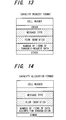
- the RNC 1 Upon receiving packet data from the CN 4, the RNC 1 buffers the packet data temporarily and transmits a request for transmission of the received packet data to Node B 2 in a control frame referred to as a "capacity request". Characteristic parameters of a capacity request are as follows, as illustrated in Fig. 13:
- Node B 2 Upon receiving a capacity request, Node B 2 examines the status of the buffer in Node B. If the buffer is empty, then Node B 2 reports the number of data items whose transmission is allowed to the RNC 1 by a control frame referred to as "capacity allocation". Characteristic parameters of capacity allocation are as follows, as illustrated in Fig. 14:
- the RNC 1 Upon receiving the capacity allocation, the RNC 1 sends the Node B 2 the buffered packet data in an amount equivalent to the number of items of data allowed. The Node B 2 subsequently transmits this packet data toward the UE 3a together with HS-SCCH data.
- the above-mentioned flow control is carried out on a per-data-flow basis (on a per-mobile-station basis). In actuality, therefore, flow control operations are performed between the RNC and Node B in parallel in a number equivalent to the data flows (the number of mobile stations).
- the RNC 1 when the RNC 1 has received packet data from the CN 4, it buffers the data temporarily and issues a packet-data transmission request to Node B by a capacity request.
- the RNC 1 transmits the capacity request whenever packet data is received from the CN 4.
- the transmission request is issued often and efficiency is poor in terms of the transmission band and computation processing resources.
- the RNC 1 exercises control that includes monitoring the buffer periodically, as illustrated in Fig. 12, starting up capacity request processing whenever monitoring is performed and issuing a transmit request to Node B 2 for all packet data buffered up to this point.
- the RNC 1 transmits the capacity request to Node B 2 with respect to each of the items of packet data 1 ⁇ , 2 ⁇ to 4 ⁇ and 5 ⁇ , receives the capacity allocation from Node B 2 and transmits the packet data to Node B. In such case data is received by Node B 2 three times. In actuality, however, it is required that the timing at which data is transmitted to the UE 3 be made to conform the HS-PDSCH minimum receive interval T 1 of the UE. Each of these items of data, therefore, is buffered in the Node B by this timing.
- the RNC 1 transmits a capacity request to Node B 2 with regard to packet data 6 ⁇ to at the start-up timing of capacity-request processing, and then transmits data to Node B 2 after a capacity allocation is received.
- data buffering time in the RNC 1 is long regardless of the fact that the UE 3 is capable of receiving the packet data at comparatively short cycles. Consequently, the time it takes for the data that arrives first (e.g., packet data 6 ⁇ , 7 ⁇ ) to actually be transferred to the UE 3 is long and arrival of data is delayed.
- packet data 6 ⁇ , 7 ⁇ the time it takes for the data that arrives first (e.g., packet data 6 ⁇ , 7 ⁇ ) to actually be transferred to the UE 3 is long and arrival of data is delayed.
- the buffer will be inadequate. Installing a large buffer in order to solve this problem is disadvantageous in terms of the size and cost of the apparatus.
- the HS-PDSCH minimum receive interval T 1 of UE 3 differs for every UE owing to the reception capability of the UE 3, as mentioned above.
- a "fixed-period capacity-request processing start-up method" of the kind normally carried out therefore, it is difficult to apply a capacity-request processing start-up period that is optimum for all UEs.
- Patent Reference 1 There is a packet switching apparatus (Patent Reference 1) that transmits multimedia information to a repeater line in a packet format and performs packet transfer in mutual fashion.
- This packet switching apparatus data information that has entered from a data terminal is stored in a buffer temporarily and is sent to the repeater line via a packet transfer unit after a transmission latency time predetermined for every type of data-information packet signal.
- this prior art implements flow control of packets, it does not relate to flow control between a base station controller and a base station in a wireless communication network that includes a base station controller, base stations and mobile stations, and it does not exercise flow control based upon the data receive interval of a mobile station.
- Patent Reference 2 there is a data transfer rate control scheme (Patent Reference 2) that optimizes data transfer rate.
- This data transfer rate control scheme performs a computation for increasing or decreasing the transmit interval depending upon whether or not flow control information, which instructs that data transmission be halted, has been sent from a transmission source within a certain period, and transmits the data of the next period at a new transmit interval obtained by the result of computation.
- the transmit interval is changed in accordance with the conditions of flow control and the data transfer rate is optimized.
- this prior art controls the transmit interval, it does not relate to flow control between a base station controller and a base station in a wireless communication network that includes a base station controller, base stations and mobile stations, and it does not exercise flow control based upon the data receive interval of a mobile station.
- an object of the present invention is to so arrange it that efficient flow control (capacity-request start-up control) that is aware of the HS-PDSCH minimum receive interval can be implemented.
- Another object of the present invention is to so arrange it that high-quality communication can be implemented by varying the HS-PDSCH minimum receive interval dynamically depending upon a difference in various operating conditions and causing the flow-control start-up period to fall in line with the minimum receive interval.
- the present invention relates to control of data flow from a base station controller to a base station in a wireless communication network that includes a base station controller, a base station and a mobile station.
- the base station controller sends and receives a data-transfer request frame and a data-transfer enable frame to and from the base station to thereby control flow of data to the base station, and the base station sends and receives data to an from the mobile station.
- the base station controller performs the flow control between itself and the base station at a prescribed processing timing, namely based upon a data receive interval of the mobile station, and the base station transmits data to the mobile station at this data receive interval.
- the above-mentioned flow control is performed on a per-mobile-station basis.
- the base station controller stores data directed toward the mobile station in a buffer on a per-mobile-station basis, performs monitoring to determine whether data occupancy (amount of data) of the buffer on a per-mobile-station basis has exceeded a predetermined threshold value, and starts flow control irrespective of processing timing if the threshold value is exceeded.
- the base station controller changes the data receive interval of the mobile station dynamically on a per-mobile-station basis in accordance with a change in communication conditions, e.g., number of times the mobile station has moved from one cell to another, communication quality, etc.
- data flow control between a base station controller and a base station and sending/receiving of data between a base station and a mobile station can be carried out at the same time.
- transmission band and computation resources are no longer wasted.
- a base station controller performs flow control between itself and a base station and transmits data to the base station. This is advantageous in terms of apparatus size and cost because it is no longer necessary to install a large buffer.
- the data receive interval of the mobile station is changed dynamically on a per-mobile-station basis in accordance with a change in communication conditions, e.g., number of times the mobile station has moved from one cell to another, communication quality, etc.
- a change in communication conditions e.g., number of times the mobile station has moved from one cell to another, communication quality, etc.
- Fig. 1 is a diagram showing the general configuration of a communication system according to the present invention. The diagram illustrates the functions of nodes and the paths of logical information exchange among these functions.
- a base station controller (RNC) 1 is equipped with at least a transceiver 11, a flow control execution unit 12, an HS-PDSCH minimum receive-interval management unit 13 and a UE mobility management unit 14.
- the transceiver 11 executes processing for sending and receiving packet data to and from a base station 2 based upon flow control.
- the flow control execution unit 12 performs flow control between itself and the base station (Node B) 2 on a per-mobile-station basis and exercises control in such a manner that packet data of each mobile station received from a core network (CN) is transmitted to the base station.
- Flow control refers to control for transmitting a data-transfer request (capacity request) frame to the base station when it is desired to transmit data to Node B 2, receive a data-transfer enable (capacity allocation) frame sent from the Node B 2 in response to the data-transfer request frame, and transmit data, which has been stored in a buffer, based upon the data-transfer enable frame.
- the flow-control start-up processing timing is decided based upon the minimum receive interval, which is specified for every mobile station, from the HS-PDSCH minimum receive-interval management unit 13. If the HS-PDSCH minimum receive-interval management unit 13 has updated the HS-PDSCH minimum receive interval of the mobile station, then reference is had to the updated HS-PDSCH minimum receive interval and flow control is continued. Further, the flow control execution unit 12 stores packet data, which is directed toward each mobile station and is received from the core network (CN), in a buffer. When the amount of data accumulated in the buffer exceeds a threshold value, however, the flow control execution unit 12 starts flow control.
- CN core network
- the HS-PDSCH minimum receive-interval management unit 13 has means for updating and then storing the minimum transmit interval of the HS-PDSCH for every mobile station (UE) 3. That is, in response to a change request from the UE mobility management unit 14, or upon receiving a request to change the HS-PDSCH minimum receive interval from the mobile station (UE) 3 or base station (Node B) 2, the HS-PDSCH minimum receive-interval management unit 13 updates and saves the value of the HS-PDSCH minimum receive interval of the UE 3.
- the HS-PDSCH minimum receive-interval management unit 13 updates the value of the HS-PDSCH minimum receive interval of the UE 3, it reports the value to the UE 3 and Node B 2 and notifies the flow control execution unit 12 of the fact that the value has changed.
- the UE mobility management unit 14 monitors the travel of the UE 3 and performs management based upon an application message. If a certain UE satisfies prescribed conditions, it requests the HS-PDSCH minimum receive-interval management unit 13 to change the HS-PDSCH minimum receive interval of the corresponding UE. For example, the UE mobility management unit 14 manages control information relating to travel of the UE 3, monitors the frequency of handover or the frequency of position registration or the frequency of cell update, determines based upon these frequencies whether it is necessary to change the data receive interval of the UE 3, and requests the HS-PDSCH minimum receive-interval management unit 13 to make a change if it is necessary to change the HS-PDSCH minimum receive interval.
- the application message between the RNC 1 and UE 3, the request to change the minimum receive interval and the notification of updating are sent and received using the dedicated control channel 5 ⁇ in Fig. 10. Further, the request to change the minimum receive interval between the RNC 1 and Node B 2 and the notification of updating are performed via the control channel 6 ⁇ between the RNC and Node B.
- the base station (Node B) 2 is equipped with at least a transceiver 20, a radio transceiver 21, a flow control execution unit 22, a HS-PDSCH minimum receive-interval management unit 23 and a radio quality management unit 24.
- the transceiver 20 executes processing to send and receive packet data to and from the base station controller (RNC) 1 based upon flow control.
- the radio transceiver 21 holds the data receive interval (minimum receive interval) on the HS-PDSCH of each mobile station (UE) 3 and transmits packets to the mobile station wirelessly based upon the data receive interval.
- the flow control execution unit 22 saves the packet data, which is received from the RNC 1 and directed toward each mobile station, in a buffer. Further, the flow control execution unit 22 has function for sending back a data-transfer enable (capacity allocation) frame in response to the data-transfer request (capacity request) frame received from the RNC 1. That is, when it receives the data-transfer request frame, which relates to a prescribed base station, from the RNC 1, the flow control execution unit 22 sends the RNC 1 the data-transfer enable frame that allows data transfer of a prescribed amount of data based upon the availability status of the buffer of this mobile station.
- the HS-PDSCH minimum receive-interval management unit 23 updates and stores the HS-PDSCH minimum receive interval for every UE 3. That is, based upon a change request from the radio quality management unit 24, the HS-PDSCH minimum receive-interval management unit 23 requests the HS-PDSCH minimum receive-interval management unit 13 of the RNC 1 to change the HS-PDSCH minimum receive interval of the applicable UE 3. Then, based upon a command to change the minimum receive interval from the HS-PDSCH minimum receive-interval management unit 13, the HS-PDSCH minimum receive-interval management unit 23 updates and stores the HS-PDSCH minimum receive interval of the applicable UE. Further, if it updates the value of the HS-PDSCH minimum receive interval of the UE 3, then the HS-PDSCH minimum receive-interval management unit 23 notifies the radio transceiver 21 of the fact that the value has changed.
- the radio quality management unit 24 monitors and manages the radio quality of every UE and, if the radio quality of a certain UE satisfies prescribed conditions, the radio quality management unit 24 notifies the HS-PDSCH minimum receive-interval management unit 23 so as to change the HS-PDSCH minimum receive interval of the UE.
- the mobile station (UE) 3 is equipped with at least a transceiver 31, an HS-PDSCH minimum receive-interval management unit 32 and a status management unit 33.
- the transceiver 31 executes processing for sending and receiving packet data and other data.
- the HS-PDSCH minimum receive-interval management unit 32 updates and stores its own HS-PDSCH minimum receive interval. That is, based upon a change request from the status management unit 33, the HS-PDSCH minimum receive-interval management unit 32 requests the HS-PDSCH minimum receive-interval management unit 13 of the RNC 1 to change its own HS-PDSCH minimum receive interval. Then, based upon a command to change the minimum receive interval from the HS-PDSCH minimum receive-interval management unit 13, the HS-PDSCH minimum receive-interval management unit 32 updates and stores the HS-PDSCH minimum receive interval. Further, if it updates the value of the HS-PDSCH minimum receive interval, then the HS-PDSCH minimum receive-interval management unit 32 notifies the radio transceiver 31 of the fact that the value has changed.
- the status management unit 33 monitors and manages its own status and, if its own status satisfies prescribed conditions, notifies the HS-PDSCH minimum receive-interval management unit 32 so as to change the HS-PDSCH minimum receive interval.
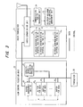
- Fig. 2 is a diagram showing the structure the a base station controller (RNC) 1 having the components of a flow control execution unit. Components identical with those of Fig. 1 are designated by like reference characters.
- the transceiver 11 is divided into a transceiver 11a for sending and receiving frames to and from base station (Node B), and a transceiver 11b for sending and receiving packets to and from the core network CN.
- the flow control execution unit 12 exercises flow control between itself and Node B with respect to packet data received from the CN via the transceiver 11b.
- Flow-control start-up processing timing is based upon the minimum receive interval specified for every UE by the HS-PDSCH minimum receive-interval management unit 13.
- the flow control execution unit 12 has a function whereby if the HS-PDSCH minimum receive interval has been updated, reference is had to the updated minimum receive interval and flow control is continued.
- Buffers 51 0 to 51 n store, for every mobile station, packet data received from the core network CN and destined for each mobile station. If packet data directed toward each mobile station has been buffered in the buffers 51 0 to 51 n on a per-mobile-station basis, a data-transfer request / enable processor (capacity request / allocation processor) 52 generates a data-transfer request frame (capacity-request frame) at a prescribed timing and transmits the frame to the Node B 2 via the transceiver 11a.
- a data-transfer request / enable processor (capacity request / allocation processor) 52 generates a data-transfer request frame (capacity-request frame) at a prescribed timing and transmits the frame to the Node B 2 via the transceiver 11a.
- the capacity-request / allocation processor 52 notifies a buffer management unit 53 of the number of items of data whose transmission has been allowed by the frame.
- the buffer management unit 53 monitors the status of the buffers at all times. That is, the buffer management unit 53 manages threshold values of the buffers 51 0 to 51 n on a per-mobile-station basis, performs monitoring to determine whether data occupancy (amount of data) in the buffer of a certain mobile station has exceeded a predetermined value and, if the threshold value has been exceeded, requests the capacity-request / allocation processor 52 to start up processing for transmitting a capacity-request frame.
- the buffer management unit 53 extracts the specified number of items of data from a data buffer 51 j conforming to this mobile station and executes transmit processing (delivers the data to the transceiver 11a).
- HS-PDSCH minimum receive interval registers 54 0 to 54 n store HS-PDSCH minimum receive intervals T MR0 to T MRn of every UE.
- the HS-PDSCH minimum receive intervals T MR0 to T MRn are used as flow-control start-up timer values and the values are updated by control executed by the HS-PDSCH minimum receive-interval management unit 13.
- Flow-control start-up timers 55 0 to 55 n are provided for each of the UEs and use, as timer values, the values of the HS-PDSCH minimum receive intervals T MR0 to T MRn that have been stored in the HS-PDSCH minimum receive interval registers 54 0 to 54 n .
- the flow-control start-up timers 55 0 to 55 n instruct the capacity-request / allocation processor 52 to execute flow control whenever elapsed time becomes equal to the timer value, and then initialize the elapsed time.
- the HS-PDSCH minimum receive-interval management unit 13 manages the HS-PDSCH minimum receive interval on a per-UE basis, receives a request to change the HS-PDSCH minimum receive interval from the UE mobility management unit 14, Node B 2 or UE 3 and updates the value of the HS-PDSCH minimum receive interval of this UE.
- the travel information management unit 14 has a function for monitoring the travel of the UE 3 and performing management based upon an application message. If a certain UE satisfies prescribed conditions, it requests the HS-PDSCH minimum receive-interval management unit 13 to change the HS-PDSCH minimum receive interval of the corresponding UE.
- the transceiver 11a terminates all data sent and received between the RNC 1 and base station 2. Packet data and an accompanying flow control frame (capacity-request / allocation frame) or application message (a request to change the minimum receive interval) on a dedicated control channel also are sent and received via the transceiver 11a.
- Packet data and an accompanying flow control frame (capacity-request / allocation frame) or application message (a request to change the minimum receive interval) on a dedicated control channel also are sent and received via the transceiver 11a.
- Fig. 3 is a diagram showing the structure of the base station (Node B) 2 having the components of the flow control execution unit / radio transceiver. Components identical with those of Fig. 1 are designated by like reference characters.
- the flow control execution unit 22 has a function for exercising flow control between itself and the RNC 1 as well as a function for storing transmit data (packet data), which is directed toward each UE, in buffers 63 0 to 63 n temporarily, and transfers the transmit data of each UE 3 to the radio transceiver 21.
- a capacity-request frame is received from the RNC 1
- a data-transfer request / enable processor (capacity request / allocation processor) 61 queries a buffer management unit 62 and acquires the number of items of data allowed for transmission, generates a capacity-allocation frame that includes the number of items of data allowed for transmission and transmits the frame to the RNC 1 via the transceiver 20.
- the buffer management unit 62 monitors the status of the buffers 63 0 to 63 n , which temporarily store the data directed toward each of the UEs, at all times. That is, when a query regarding number of items of data allowed for transmission enters from the capacity-request /allocation processor 61, the buffer management unit 62 investigates the buffer status of the applicable UE, decides, in accordance with the availability status of the buffer, the number of items of data allowed for transmission and reports this to the capacity-request /allocation processor 61. Further, the buffer management unit 62 also has a function for delivering the data in the buffers 63 0 to 63 n to the radio transceiver 21.
- the radio transceiver 21 is a functional unit for actually performing wireless communication with each UE 3.
- a radio communication unit 71 wirelessly transmits packet data of each UE delivered from the buffer management unit 62 of the flow control execution unit to the UE at the minimum receive interval.
- the radio communication unit 71 refers to data receive intervals TMr 0 to TMR n of each of the UEs being held in HS-PDSCH minimum receive interval registers 72 0 to 72 n and performs communication while assuring the minimum receive interval of each UE.
- the UE 3 notifies the communication quality management unit 24 of communication quality information (ACK, NACK) receives via the HS-PDSCH 4 ⁇ in Fig. 10.
- the HS-PDSCH minimum receive interval registers 72 0 to 72 n manage and store the data receive intervals TMr 0 to TMR n on a per-UE basis. These are referred to by the radio communication unit 71 and the values are updated by the HS-PDSCH minimum receive-interval management unit 23.
- the communication quality management unit 24 determines whether it is necessary to change the HS-PDSCH minimum receive interval. If it is determined that a change is necessary, the communication quality management unit 24 uses the control channel 6 ⁇ (see Fig. 10 between the RNC and Node B and reports the change request to the RNC 1.
- the processing for changing the receive interval can be implemented as set forth below.
- the ratio of NACK (reception failure) in the communication quality information (ACK, NACK) received within a unit of time is compared with two types of threshold values (upper and lower limits), the minimum receive interval is enlarged if the ratio is greater than the upper-limit threshold value) (i.e., if quality is low), and the minimum receive interval is reduced if the ratio is less than the lower-limit threshold value) (i.e., if quality is high).
- the amount of change in the minimum receive interval can be specified as a multiple n (where n is an integer) of the TTI (2 ms).
- the HS-PDSCH minimum receive-interval management unit 23 manages the minimum receive interval of the HS-PDSCH on a per-UE basis, receives a request to change the HS-PDSCH minimum receive interval from the communication quality management unit 24 and updates the value of the HS-PDSCH minimum receive interval of the applicable UE held in the HS-PDSCH minimum receive interval registers 72 0 to 72 n .
- the change request is sent to the RNC 1 and the HS-PDSCH minimum receive interval registers 72 0 to 72 n are updated after notification of updating is received from the RNC 1.
- the transceiver 20 terminates all data sent and received between the Node B 2 and RNC 1. Packet data and an accompanying flow control frame (capacity-request /allocation frame) or control message (a request to change the minimum receive interval) between the RNC and Node B also are sent and received via the transceiver 20.
- Packet data and an accompanying flow control frame (capacity-request /allocation frame) or control message (a request to change the minimum receive interval) between the RNC and Node B also are sent and received via the transceiver 20.
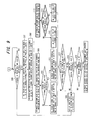
- Fig. 4 is the processing sequence of flow control in the base station controller (RNC).
- RNC base station controller
- Packet data from the CN received from the transceiver 11b is stored in the buffers 51 0 to 51 n on a per-UE basis (step 1 ⁇ ).
- the buffer management unit 53 monitors the data occupancy (amount of accumulated data) in the buffers at all times (step 2 ⁇ ). If it is detected that the buffer occupancy has exceeded a predetermined threshold value, the buffer management unit 53 immediately so notifies the capacity-request / allocation processor 52 and triggers start-up of flow control (step 2 ⁇ ').
- the flow-control start-up timers 55 0 to 55 n are started up independently on a per-UE basis and measure elapsed time. Reference is had to the HS-PDSCH minimum receive interval and monitoring is performed to determine whether elapsed time has reached the HS-PDSCH minimum receive interval (step 3 ⁇ ). If the elapsed time has reached the HS-PDSCH minimum receive interval, then the capacity-request /allocation processor 52 is so notified and start-up of flow control is triggered (step 3 ⁇ '). Further, the measured time is initialized and start-up is performed again from zero. When a timer runs out of time, it is possible to start up flow control periodically in a form that falls in line with the HS-PDSCH minimum receive interval up on a per-UE basis in the manner described above.
- the capacity-request / allocation processor 52 detects the flow-control start-up trigger. In response, the capacity-request / allocation processor 52 passes buffer status between itself and the buffer management unit 53, creates a capacity-request frame based upon this information and transmits it to Node B 2 (step 4 ⁇ ).
- the capacity-request / allocation processor 52 Upon receiving a capacity-allocation frame from the Node B 2 (step 5 ⁇ ), the capacity-request / allocation processor 52 checks the number of items of packet data allowed for transmission (step 6 ⁇ ), extracts this number of items of transmit packet data from the buffers 51 0 to 51 n and transmits the data to Node B 2 (step 7 ⁇ ).
- a guard time is provided on a per-user basis and protection is furnished in such a manner that two or more capacity-request frames will not be transmitted in the guard time.
- This control method is capable of being implemented by providing a timer for every user.
- Fig. 5 illustrates processing for flow control between the RNC and Node B. It should be noted that steps 101 to 108 in Fig. 5 have already been explained in accordance with the sequence of Fig. 4 and need not be described again. That is, what is described below is processing that follows the generation and transmission of the capacity-request frame by the RNC 1.
- the capacity-request / allocation processor 61 of Node B 2 specifies the mobile station UE from the received capacity-allocation frame and checks the number of items of data requested for transmission (step 110).
- the capacity-request / allocation processor 61 queries the buffer management unit 62 concerning the amount of available buffer for the applicable mobile station UE (step 111).
- the buffer management unit 62 checks the amount of available buffer for the mobile station UE, decides the number of items of data allowed for transmission and notifies the capacity-request / allocation processor 61 of the number of items of data allowed for transmission with regard to the UE (step 112).
- the capacity-request / allocation processor 61 On the basis of the number of transmittable items of data reported by the buffer management unit 62, the capacity-request / allocation processor 61 generates a capacity-allocation frame and sends it back to the RNC 1 via the transceiver 20.
- the capacity-request / allocation processor 52 of RNC 1 Upon receiving the capacity-allocation frame from the Node B 2, the capacity-request / allocation processor 52 of RNC 1 specifies the mobile station (user), extracts the number of items of data allowed for transmission and so notifies the buffer management unit 62 (step 114). On the basis of the number of transmittable items of data reported, the buffer management unit 62 reads a packet out of the buffer of the applicable UE and transmits it to the Node B 2 via the transceiver 11a (step 115). Upon receiving the packet data from the RNC 1, the Node B 2 stores the data in the buffer of the applicable mobile station UE.
- Fig. 6 illustrates processing for data transfer between Node B and a UE.
- the radio transceiver 21 of Node B 2 makes preparations constantly for a transmission to each UE using the HS-PDSCH minimum receive interval of each UE as a reference (step 201).
- the radio communication unit 71 queries the buffer management unit 62 concerning the buffer status of this UE (step 203).
- the buffer management unit 62 checks to see whether data exists in the buffer of this UE (step 204) and repeats the processing from step 201 onward if data is absent. If data exists in the buffer, on the other hand, the buffer management unit 62 transfers this data to the radio communication unit 71 (step 206).
- the radio communication unit 71 transmits control data to this UE via the HS-SCCH (step 207) and transmits packet data wirelessly via the HS-PDSCH (step 208).
- the UE 3 receives the control data via the HS-SCCH (step 209) and receives the packet data via the HS-PDSCH (step 210) using the reception parameters (radio spread-spectrum, modulation scheme and data-length information, etc.) contained in the control data.
- the UE 3 performs monitoring to determine whether the data has been received normally (step 211) and transmits ACK (verification of normal reception) to Node B 2 via the HS-PDSCH (step 212) if the data has been received normally. If the data has not been received normally, the UE 3 transmits NACK (failure of data reception) to the Node B 2 via the HS-PDSCH (step 213).
- Node B 2 transfers the ACK/NACK information to the communication quality management unit 24 via the radio communication unit 71 (step 214), and the communication quality management unit 24 retains the ACK/NACK information as radio quality information and uses the information in subsequent feedback processing (specifically, in processing for changing the HS-PDSCH minimum receive interval) (step 215).
- a series of transmit processing operations (flow control between RNC and Node B and data transfer between Node B and UEs) is performed at a timing that falls in line with HS-PDSCH minimum receive interval T MR of UE 3, as illustrated in Fig. 7.
- T MR HS-PDSCH minimum receive interval
- Figs. 8 and 9 are processing flowcharts for updating the minimum receive interval (data receive interval) of each UE.
- the travel information management unit 14 within the RNC 1 stores and manages UE travel information, e.g., frequency of handover and cell updating (step 301).
- the travel information management unit 14 performs monitoring to determine whether the frequency of handover or cell updating has fallen below a predetermined lower-limit threshold value or exceeded a predetermined upper-limit threshold value (steps 302, 303). If the upper-limit threshold value is exceeded, the travel information management unit 14 requests the HS-PDSCH minimum receive-interval management unit 13 to enlarge the value of the HS-PDSCH minimum receive interval (step 304). If the lower-limit threshold value is exceeded, the travel information management unit 14 requests the HS-PDSCH minimum receive-interval management unit 13 to diminish the value of the HS-PDSCH minimum receive interval (step 305).
- the HS-PDSCH minimum receive-interval management unit 13 performs monitoring to determine whether a change in the value of the HS-PDSCH minimum receive interval has been requested (step 306; Fig. 9). If a change has been requested, the HS-PDSCH minimum receive-interval management unit 13 changes the value of the HS-PDSCH minimum receive interval, which is being held in the minimum receive interval register of the applicable UE within the flow control execution unit 12, by increasing or decreasing the value by n steps in accordance with the change request.
- the HS-PDSCH minimum receive-interval management unit 13 uses the control channel (see Fig. 10) between the RNC and Node B to notify the Node B 2 that the HS-PDSCH minimum receive interval will be changed (step 307).
- the HS-PDSCH minimum receive-interval management unit 13 uses the dedicated control channel 5 ⁇ (Fig. 10) to notify the UE 3 that the HS-PDSCH minimum receive interval will be changed (step 308).
- the HS-PDSCH minimum receive-interval management unit 23 of Node B 2 changes the HS-PDSCH minimum receive interval by the number of steps reported from the RNC 1 (step 309) and checks to determine whether the change in minimum receive interval has succeeded (step 310). If the change in minimum receive interval has not succeeded, the HS-PDSCH minimum receive-interval management unit 23 notifies the RNC 1 of the change failure (step 311). If the change in the minimum receive interval succeeds, however, the HS-PDSCH minimum receive-interval management unit 23 notifies the RNC 1 of the fact that the change succeeded (step 312).
- the HS-PDSCH minimum receive-interval management unit 32 of UE 3 changes the HS-PDSCH minimum receive interval by the number of steps reported from the RNC 1 (step 313) and checks to determine whether the change in minimum receive interval has succeeded (step 314). If the change in minimum receive interval has not succeeded, the minimum receive-interval management unit 32 notifies the RNC 1 of the change failure (step 315). If the change in the minimum receive interval succeeds, however, the minimum receive-interval management unit 32 notifies the RNC 1 of the fact that the change succeeded (step 316).
- the HS-PDSCH minimum receive-interval management unit 13 of the RNC 1 performs monitoring to determine whether notification of change success/failure has been received from the Node B 2 and UE 3 within a fixed period of time, whether Node B has succeeded in making the change of the receive interval and whether the UE has succeeded in making the change of the receive interval (steps 317 to 319). If notification of change success/failure has not been received, or if node B has failed in making the change in the receive interval, or if the UE has failed in making the change in the receive interval, then the HS-PDSCH minimum receive-interval management unit 13 instructs Node B 2 and UE 3 to restore the minimum receive interval to the original value (step 320).
- the HS-PDSCH minimum receive-interval management unit 13 updates the minimum receive interval of the applicable UE (step 321).
- the communication quality management unit 24 (Fig. 1) of the Node B 2 ascertains the wireless communication status of packet data using ACK/NACK information received from the UE 3 via the HS-PDSCH (step 401).
- the communication quality management unit 24 manages, for every UE, the result of measuring radio communication quality and changes the HS-PDSCH minimum receive interval. That is, if the retransmission frequency of packet data is high and radio quality is less than the lower-limit threshold value ("YES" at step 403), then there is the possibility that receive processing at the UE 3 is not keeping up. In such case the communication quality management unit 24 instructs the HS-PDSCH minimum receive-interval management unit 23 to make a change so as to increase the value of the HS-PDSCH minimum receive interval. As a result, the HS-PDSCH minimum receive-interval management unit 23 requests the minimum receive-interval management unit 13 of RNC 1 to make a change so as to increase the value of the HS-PDSCH minimum receive interval by n steps (step 404).
- the communication quality management unit 24 instructs the HS-PDSCH minimum receive-interval management unit 23 to make a change so as to decrease the value of the HS-PDSCH minimum receive interval.
- the HS-PDSCH minimum receive-interval management unit 23 requests the minimum receive-interval management unit 13 of RNC 1 to make a change so as to decrease the value of the HS-PDSCH minimum receive interval by n steps (step 405). Processing from step 306 onward in Fig. 9 is thenceforth executed.
- the UE In accordance with the communication status, etc., of the UE 3, the UE notifies the RNC 1 of the trigger that changes the HS-PDSCH minimum receive interval.
- a dedicated control channel is used as the method of notification. For example, it is considered useful to monitor the amount of remaining battery in the UE 3 (step 501) and, if there is little battery remaining, to extend the data receive interval in order to suppress power consumption. In this case, the amount of remaining battery is managed by the status management unit 33 (see Fig. 1). If the amount of remaining battery falls below a predetermined threshold value (step 502), then the status management unit 33 instructs the HS-PDSCH minimum receive-interval management unit 32 to make a change so as to increase the minimum receive interval by n steps.
- the minimum receive-interval management unit 32 requests the minimum receive-interval management unit 13 of RNC 1 to make a change so as to increase the value of the HS-PDSCH minimum receive interval by n steps (step 503). Processing from step 306 onward in Fig. 9 is thenceforth executed.
- the value of the minimum receive interval is changed based upon the amount of remaining battery.
- the value can also be changed based upon communication quality or communication rate. That is, in general the UE 3 measures the communication quality. It is possible to use a dedicated control channel to notify the RNC to implement a threshold-value judgment based upon the measured reception quality, increase the minimum receive interval by n steps if the reception quality has declined and decrease the minimum receive interval by n steps if the reception quality has improved.
- the UE 3 measures the communication rate. It is possible to use a dedicated control channel to notify the RNC to implement a threshold-value judgment based upon the measured communication rate, increase the minimum receive interval by n steps if the communication rate is low and decrease the minimum receive interval by n steps if the communication rate is high. This makes it possible to prevent needless consumption of power when communication is performed at a low rate.
- a very important problem that will accompany speed-up of packet transmission rate in the future is how to use limited resources (transmission band, buffer memory, computation resources, etc.).
- attention is actually directed toward the reception operation of a UE, which is the terminus of packet data, and flow control processing is started up on the RNC side in accordance with the period at which the UE is capable of receiving data.
- Flow control is performed independently with respect to a plurality of UEs.
Landscapes
- Engineering & Computer Science (AREA)
- Computer Networks & Wireless Communication (AREA)
- Signal Processing (AREA)
- Databases & Information Systems (AREA)
- Mobile Radio Communication Systems (AREA)
- Data Exchanges In Wide-Area Networks (AREA)
Abstract
Disclosed is a method of controlling flow between a
base station controller and a base station in a wireless
communication network. The base station controller, base
station and a mobile station are provided with the same
processing timing that is based upon the minimum receive
interval of the mobile station. The base station
controller sends and receives a data-transfer request
frame and a data-transfer enable frame to and from the
base station and performs flow control of data from the
base station controller to the base station, and the base
station transmits data to the mobile station at the
processing timing.
Description
This invention relates to a wireless communication
network, which includes at least a base station
controller (Radio Network Controller: RNC), a base
station (Node B) and a mobile station (User Equipment:
UE), and to a flow control method. More particularly,
the invention relates to wireless communication network
and flow control method for performing flow control
efficiently by making the processing intervals of flow
control, which is implemented between the RNC and Node B,
coincide.
A wireless communication system that employs the W-CDMA
scheme has been standardized by the 3GPP (3rd
Generation Partnership Project) and actual service has
begun in Japan as well. With 3GPP at the present time,
standardization of additional functions is progressing
with the aim of providing further functionality. For
example, in packet communication, a study of additional
functions for raising the communication rate to a maximum
of 12 Mbps on the downlink (at present the maximum rate
on the downlink is 2 Mbps) is being carried out under the
name HSDPA (High Speed Data Packet Access).
Fig. 10 is a schematic view of the configuration of
an HSDPA system. A radio access system (RAN: Radio
Access Network) in 3GPP comprises an RNC (Radio Network
Controller) 1, a Node B (base station) 2 and UEs (User
Equipment: mobile stations) 3a, 3b, ···. The RAN is
connected to a CN (Core Network) 4.
With HSDPA, a 1 ○ HS-DSCH (High Speed - Downlink
Shared Channel) in a wired section and a 1 ○ HS-PDSCH
(High Speed - Physical Downlink Shared Channel) in a
wireless section are used as packet-data transmission
channels CH. HS-DSCH and HS-PDSCH are channels
exclusively for the downlink and are shared by a
plurality of UEs (UE #0, UE #1) 3a, 3b, ···.
In a wireless section, a HS-SCCH 3 ○ (High Speed
Shared Control Channel) is set up as a high-speed control
channel, and control information for allowing the UEs 3a,
3b, ··· to receive packet data on the HS-PDSCH is
transmitted. The HS-SCCH is shared by a plurality of the
UEs 3a,3b, ···.
Further, in a wireless section, a 4 ○ HS-DPCCH (High
Speed Dedicated Physical Control Channel) is set up on a
per-user basis. With HSDPA, data retransmission control
is exercised between the Node B 2 and the UEs 3a, 3b, ···.
The UEs 3a, 3b, ··· report ACK (notification of
acknowledgement of reception) or NACK (notification of
reception failure) with respect to the receive data to
the Node B 2 using the HS-DPCCH.
A logic path (dedicated control channel) 5 ○ for
control is set up for every UE 3a, 3b, ··· between the
RNC 1 and UEs 3a, 3b, ···. It should be noted that the
data on the dedicated control channel is physically sent
and received via the Node B 2. Further, the sending and
receiving of control information between the RNC 1 and
Node B 2 is performed via 6 ○ the control channel between
the RNC and Node B. In addition, in order to assure QoS
(Quality of Service), flow control is carried out between
the RNC 1 and Node B 2.
Figs. 11(A) to 11(D) are diagrams useful in
describing a mechanism for receiving packet data on the
HS-PDSCH.
As shown at (A) of Fig. 11, a transmit cycle
referred to as a "TTI" (Transmission Time Interval = 2
ms) is set up on the HS-SCCH. Control information is
transmitted in conformity with the TTI and received by
UEs # 0, #1 only if control information to be transmitted
exists. The data transmitted on the HS-SCCH includes a
user identifier (UEID: User Equipment Identifier) and
various parameters (radio spectrum code, modulation
scheme, data-length information, etc.) for receiving data
on the HS-PDSCH.
UE receives HS-SCCH data in all TTIs. For example,
in slot # 1 at (B) of Fig. 11, UE #1 and UE #2 receive the
HS-SCCH data simultaneously. Each UE refers to the UEID
in the data and compares it with its own ID. In this case,
the UEID of the HS-SCCH data in slot # 1 is "UE #1", and
therefore UE #0 discards the receive HS-SCCH data and UE
# 1 loads the control data contained in the receive HS-SCCH
data. UE # 1 thenceforth extracts a parameter, which
is for HS-PDSCH receive, from the control data portion,
and receives the packet data on the HS-PDSCH [(C), (D) of
Fig. 11].
Upon receiving data, the UE #1 refers to a "sequence
number" contained in the data and checks to determine
whether there is loss of data. In a case where all data
could be received without loss of data, the UE #1 reports
ACK to Node B using the HS-DPCCH, Further, if data has
been lost, then the UE # 1 reports NACK to Node B using
the HS-DPCCH. Operation is similar with regard to slots
# 2 to #5 and slots # 7 and #8. The UE #1 receives packet
data via the HS-PDSCH of slots # 1, #4, and the UE #0
receives packet data via the HS-PDSCH of slots # 2 and #3,
slot # 5 and slots # 7 and #8.
With a UE having a low receive processing capability,
a case where receive data processing cannot keep up when
data is received every time in every TTI is conceivable.
Accordingly, it is necessary to be able to set the
minimum receive interval on a per-UE basis and for the
Node B to assure a transmit interval that is greater than
the minimum receive interval with respect to a certain
specific UE.
For example, as indicated at (D) of Fig. 11,
consider a case where the minimum receive intervals of
the UE # 0, UE # 1 are 1TTI and 3TTI, respectively. If it
is assumed that a data transmission directed toward UE #1
has been performed in slot # 1, the next time a
transmission toward UE #1 is performed will be in slot # 4,
which is 3TTI later. A transmission toward UE #1 is
inhibited in the intervening slots # 2, #3.
Fig. 12 is a diagram useful in describing an
overview of a flow control mechanism.
Upon receiving packet data from the CN 4, the RNC 1
buffers the packet data temporarily and transmits a
request for transmission of the received packet data to
Node B 2 in a control frame referred to as a "capacity
request". Characteristic parameters of a capacity
request are as follows, as illustrated in Fig. 13:
Upon receiving a capacity request, Node B 2 examines
the status of the buffer in Node B. If the buffer is
empty, then Node B 2 reports the number of data items
whose transmission is allowed to the RNC 1 by a control
frame referred to as "capacity allocation".
Characteristic parameters of capacity allocation are as
follows, as illustrated in Fig. 14:
Upon receiving the capacity allocation, the RNC 1
sends the Node B 2 the buffered packet data in an amount
equivalent to the number of items of data allowed. The
Node B 2 subsequently transmits this packet data toward
the UE 3a together with HS-SCCH data.
The above-mentioned flow control is carried out on a
per-data-flow basis (on a per-mobile-station basis). In
actuality, therefore, flow control operations are
performed between the RNC and Node B in parallel in a
number equivalent to the data flows (the number of mobile
stations).
As described in Fig. 12, when the RNC 1 has received
packet data from the CN 4, it buffers the data
temporarily and issues a packet-data transmission request
to Node B by a capacity request.
With regard to an opportunity for transmission of
the capacity request, assume that the RNC 1 transmits the
capacity request whenever packet data is received from
the CN 4. In this case, the transmission request is
issued often and efficiency is poor in terms of the
transmission band and computation processing resources.
Normally, therefore, the RNC 1 exercises control that
includes monitoring the buffer periodically, as
illustrated in Fig. 12, starting up capacity request
processing whenever monitoring is performed and issuing a
transmit request to Node B 2 for all packet data buffered
up to this point.
Such flow control, however, has the problems set
forth below.
First, consider a case where a capacity-request
processing start-up period T0 of the RNC 1 is shorter
than an HS-PDSCH minimum receive interval T1 of UE 3, as
shown in Fig. 15.
At every capacity-request processing start-up period
T0, the RNC 1 transmits the capacity request to Node B 2
with respect to each of the items of packet data 1 ○, 2 ○ to
4 ○ and 5 ○, receives the capacity allocation from Node B 2
and transmits the packet data to Node B. In such case
data is received by Node B 2 three times. In actuality,
however, it is required that the timing at which data is
transmitted to the UE 3 be made to conform the HS-PDSCH
minimum receive interval T1 of the UE. Each of these
items of data, therefore, is buffered in the Node B by
this timing.
Thus, in a case where the capacity-request
processing start-up period T0 in the RNC 1 and the HS-PDSCH
minimum receive interval T1 of the UE differ, data
is buffered in the Node B 2 needlessly. Further, under
the circumstances shown in Fig. 15, in comparison with a
case where a single capacity request is transmitted from
the RNC 1 with respect to all data of packets 1 ○ to 5 ○,
three times as many capacity requests and capacity
allocations are sent and received. This not only wastes
the transmission band between the RNC and Node B but also
leads to waste of computation resources expended in
capacity-request processing within the RNC. Furthermore,
if data occupies the buffer in node B for a long period
of time, a problem which arises is that the buffer will
no longer be allocated to a data-transfer request
(capacity request) issued subsequently by the RNC.
Installing a large buffer in order to solve this problem
is disadvantageous in terms of the size and cost of the
apparatus.
Next, consider a case where the capacity-request
processing start-up period T0 of the RNC 1 is longer than
the HS-PDSCH minimum receive interval T1 of UE 3, as
illustrated in Fig. 16.
As shown in Fig. 16, the RNC 1 transmits a capacity
request to Node B 2 with regard to packet data 6 ○ to  at
the start-up timing of capacity-request processing, and
then transmits data to
at
the start-up timing of capacity-request processing, and
then transmits data to Node B 2 after a capacity
allocation is received. In this case, data buffering
time in the RNC 1 is long regardless of the fact that the
UE 3 is capable of receiving the packet data at
comparatively short cycles. Consequently, the time it
takes for the data that arrives first (e.g., packet data
6 ○, 7 ○) to actually be transferred to the UE 3 is long and
arrival of data is delayed. Furthermore, if data
occupies the buffer in RNC 1 for a long period of time,
there is a possibility that the buffer will be inadequate.
Installing a large buffer in order to solve this problem
is disadvantageous in terms of the size and cost of the
apparatus.
Furthermore, the HS-PDSCH minimum receive interval
T1 of UE 3 differs for every UE owing to the reception
capability of the UE 3, as mentioned above. With a
"fixed-period capacity-request processing start-up
method" of the kind normally carried out, therefore, it
is difficult to apply a capacity-request processing
start-up period that is optimum for all UEs.
There is a packet switching apparatus (Patent
Reference 1) that transmits multimedia information to a
repeater line in a packet format and performs packet
transfer in mutual fashion. With this packet switching
apparatus, data information that has entered from a data
terminal is stored in a buffer temporarily and is sent to
the repeater line via a packet transfer unit after a
transmission latency time predetermined for every type of
data-information packet signal. Although this prior art
implements flow control of packets, it does not relate to
flow control between a base station controller and a base
station in a wireless communication network that includes
a base station controller, base stations and mobile
stations, and it does not exercise flow control based
upon the data receive interval of a mobile station.
Further, there is a data transfer rate control
scheme (Patent Reference 2) that optimizes data transfer
rate. This data transfer rate control scheme performs a
computation for increasing or decreasing the transmit
interval depending upon whether or not flow control
information, which instructs that data transmission be
halted, has been sent from a transmission source within a
certain period, and transmits the data of the next period
at a new transmit interval obtained by the result of
computation. As a result, the transmit interval is
changed in accordance with the conditions of flow control
and the data transfer rate is optimized. Although this
prior art controls the transmit interval, it does not
relate to flow control between a base station controller
and a base station in a wireless communication network
that includes a base station controller, base stations
and mobile stations, and it does not exercise flow
control based upon the data receive interval of a mobile
station.
-
Patent Reference 1
Japanese Patent Application Laid-Open No. 3-108843 -
Patent Reference 2
Japanese Patent Application Laid-Open No. 7-264262
Accordingly, an object of the present invention is
to so arrange it that efficient flow control (capacity-request
start-up control) that is aware of the HS-PDSCH
minimum receive interval can be implemented.
Another object of the present invention is to so
arrange it that high-quality communication can be
implemented by varying the HS-PDSCH minimum receive
interval dynamically depending upon a difference in
various operating conditions and causing the flow-control
start-up period to fall in line with the minimum receive
interval.
The present invention relates to control of data
flow from a base station controller to a base station in
a wireless communication network that includes a base
station controller, a base station and a mobile station.
The base station controller sends and receives a data-transfer
request frame and a data-transfer enable frame
to and from the base station to thereby control flow of
data to the base station, and the base station sends and
receives data to an from the mobile station. The base
station controller performs the flow control between
itself and the base station at a prescribed processing
timing, namely based upon a data receive interval of the
mobile station, and the base station transmits data to
the mobile station at this data receive interval. In a
case where the base station communicates with a number of
base stations, the above-mentioned flow control is
performed on a per-mobile-station basis.
Further, the base station controller stores data
directed toward the mobile station in a buffer on a per-mobile-station
basis, performs monitoring to determine
whether data occupancy (amount of data) of the buffer on
a per-mobile-station basis has exceeded a predetermined
threshold value, and starts flow control irrespective of
processing timing if the threshold value is exceeded.
Further, the base station controller changes the
data receive interval of the mobile station dynamically
on a per-mobile-station basis in accordance with a change
in communication conditions, e.g., number of times the
mobile station has moved from one cell to another,
communication quality, etc.
In accordance with the present invention, data flow
control between a base station controller and a base
station and sending/receiving of data between a base
station and a mobile station can be carried out at the
same time. As a result, transmission band and
computation resources are no longer wasted.
In accordance with the present invention, it is so
arranged that if the amount of mobile-station-directed
data that has accumulated in a buffer increases, a base
station controller performs flow control between itself
and a base station and transmits data to the base station.
This is advantageous in terms of apparatus size and cost
because it is no longer necessary to install a large
buffer.
In accordance with the present invention, the data
receive interval of the mobile station is changed
dynamically on a per-mobile-station basis in accordance
with a change in communication conditions, e.g., number
of times the mobile station has moved from one cell to
another, communication quality, etc. As a result,
optimum data flow control can be carried out for every
mobile station.
Fig. 1 is a diagram showing the general
configuration of a communication system according to the
present invention. The diagram illustrates the functions
of nodes and the paths of logical information exchange
among these functions.
A base station controller (RNC) 1 is equipped with
at least a transceiver 11, a flow control execution unit
12, an HS-PDSCH minimum receive-interval management unit
13 and a UE mobility management unit 14. The transceiver
11 executes processing for sending and receiving packet
data to and from a base station 2 based upon flow control.
The flow control execution unit 12 performs flow
control between itself and the base station (Node B) 2 on
a per-mobile-station basis and exercises control in such
a manner that packet data of each mobile station received
from a core network (CN) is transmitted to the base
station. Flow control refers to control for transmitting
a data-transfer request (capacity request) frame to the
base station when it is desired to transmit data to Node
B 2, receive a data-transfer enable (capacity allocation)
frame sent from the Node B 2 in response to the data-transfer
request frame, and transmit data, which has been
stored in a buffer, based upon the data-transfer enable
frame.
The flow-control start-up processing timing is
decided based upon the minimum receive interval, which is
specified for every mobile station, from the HS-PDSCH
minimum receive-interval management unit 13. If the HS-PDSCH
minimum receive-interval management unit 13 has
updated the HS-PDSCH minimum receive interval of the
mobile station, then reference is had to the updated HS-PDSCH
minimum receive interval and flow control is
continued. Further, the flow control execution unit 12
stores packet data, which is directed toward each mobile
station and is received from the core network (CN), in a
buffer. When the amount of data accumulated in the
buffer exceeds a threshold value, however, the flow
control execution unit 12 starts flow control.
The HS-PDSCH minimum receive-interval management
unit 13 has means for updating and then storing the
minimum transmit interval of the HS-PDSCH for every
mobile station (UE) 3. That is, in response to a change
request from the UE mobility management unit 14, or upon
receiving a request to change the HS-PDSCH minimum
receive interval from the mobile station (UE) 3 or base
station (Node B) 2, the HS-PDSCH minimum receive-interval
management unit 13 updates and saves the value of the HS-PDSCH
minimum receive interval of the UE 3. Further, if
the HS-PDSCH minimum receive-interval management unit 13
updates the value of the HS-PDSCH minimum receive
interval of the UE 3, it reports the value to the UE 3
and Node B 2 and notifies the flow control execution unit
12 of the fact that the value has changed.
The UE mobility management unit 14 monitors the
travel of the UE 3 and performs management based upon an
application message. If a certain UE satisfies
prescribed conditions, it requests the HS-PDSCH minimum
receive-interval management unit 13 to change the HS-PDSCH
minimum receive interval of the corresponding UE.
For example, the UE mobility management unit 14 manages
control information relating to travel of the UE 3,
monitors the frequency of handover or the frequency of
position registration or the frequency of cell update,
determines based upon these frequencies whether it is
necessary to change the data receive interval of the UE 3,
and requests the HS-PDSCH minimum receive-interval
management unit 13 to make a change if it is necessary to
change the HS-PDSCH minimum receive interval.
The application message between the RNC 1 and UE 3,
the request to change the minimum receive interval and
the notification of updating are sent and received using
the dedicated control channel 5 ○ in Fig. 10. Further,
the request to change the minimum receive interval
between the RNC 1 and Node B 2 and the notification of
updating are performed via the control channel 6 ○ between
the RNC and Node B.
The base station (Node B) 2 is equipped with at
least a transceiver 20, a radio transceiver 21, a flow
control execution unit 22, a HS-PDSCH minimum receive-interval
management unit 23 and a radio quality
management unit 24.
The transceiver 20 executes processing to send and
receive packet data to and from the base station
controller (RNC) 1 based upon flow control. The radio
transceiver 21 holds the data receive interval (minimum
receive interval) on the HS-PDSCH of each mobile station
(UE) 3 and transmits packets to the mobile station
wirelessly based upon the data receive interval.
The flow control execution unit 22 saves the packet
data, which is received from the RNC 1 and directed
toward each mobile station, in a buffer. Further, the
flow control execution unit 22 has function for sending
back a data-transfer enable (capacity allocation) frame
in response to the data-transfer request (capacity
request) frame received from the RNC 1. That is, when it
receives the data-transfer request frame, which relates
to a prescribed base station, from the RNC 1, the flow
control execution unit 22 sends the RNC 1 the data-transfer
enable frame that allows data transfer of a
prescribed amount of data based upon the availability
status of the buffer of this mobile station.
The HS-PDSCH minimum receive-interval management
unit 23 updates and stores the HS-PDSCH minimum receive
interval for every UE 3. That is, based upon a change
request from the radio quality management unit 24, the
HS-PDSCH minimum receive-interval management unit 23
requests the HS-PDSCH minimum receive-interval management
unit 13 of the RNC 1 to change the HS-PDSCH minimum
receive interval of the applicable UE 3. Then, based
upon a command to change the minimum receive interval
from the HS-PDSCH minimum receive-interval management
unit 13, the HS-PDSCH minimum receive-interval management
unit 23 updates and stores the HS-PDSCH minimum receive
interval of the applicable UE. Further, if it updates
the value of the HS-PDSCH minimum receive interval of the
UE 3, then the HS-PDSCH minimum receive-interval
management unit 23 notifies the radio transceiver 21 of
the fact that the value has changed.
The radio quality management unit 24 monitors and
manages the radio quality of every UE and, if the radio
quality of a certain UE satisfies prescribed conditions,
the radio quality management unit 24 notifies the HS-PDSCH
minimum receive-interval management unit 23 so as
to change the HS-PDSCH minimum receive interval of the UE.
The mobile station (UE) 3 is equipped with at least
a transceiver 31, an HS-PDSCH minimum receive-interval
management unit 32 and a status management unit 33.
At the HS-PDSCH minimum receive interval, the
transceiver 31 executes processing for sending and
receiving packet data and other data. The HS-PDSCH
minimum receive-interval management unit 32 updates and
stores its own HS-PDSCH minimum receive interval. That
is, based upon a change request from the status
management unit 33, the HS-PDSCH minimum receive-interval
management unit 32 requests the HS-PDSCH minimum receive-interval
management unit 13 of the RNC 1 to change its
own HS-PDSCH minimum receive interval. Then, based upon
a command to change the minimum receive interval from the
HS-PDSCH minimum receive-interval management unit 13, the
HS-PDSCH minimum receive-interval management unit 32
updates and stores the HS-PDSCH minimum receive interval.
Further, if it updates the value of the HS-PDSCH minimum
receive interval, then the HS-PDSCH minimum receive-interval
management unit 32 notifies the radio
transceiver 31 of the fact that the value has changed.
The status management unit 33 monitors and manages
its own status and, if its own status satisfies
prescribed conditions, notifies the HS-PDSCH minimum
receive-interval management unit 32 so as to change the
HS-PDSCH minimum receive interval.
Fig. 2 is a diagram showing the structure the a base
station controller (RNC) 1 having the components of a
flow control execution unit. Components identical with
those of Fig. 1 are designated by like reference
characters. The transceiver 11 is divided into a
transceiver 11a for sending and receiving frames to and
from base station (Node B), and a transceiver 11b for
sending and receiving packets to and from the core
network CN.
The flow control execution unit 12 exercises flow
control between itself and Node B with respect to packet
data received from the CN via the transceiver 11b. Flow-control
start-up processing timing is based upon the
minimum receive interval specified for every UE by the
HS-PDSCH minimum receive-interval management unit 13.
Furthermore, the flow control execution unit 12 has a
function whereby if the HS-PDSCH minimum receive interval
has been updated, reference is had to the updated minimum
receive interval and flow control is continued. Each
block in the flow controller will now be described.
Buffers 510 to 51n store, for every mobile station,
packet data received from the core network CN and
destined for each mobile station. If packet data
directed toward each mobile station has been buffered in
the buffers 510 to 51n on a per-mobile-station basis, a
data-transfer request / enable processor (capacity
request / allocation processor) 52 generates a data-transfer
request frame (capacity-request frame) at a
prescribed timing and transmits the frame to the Node B 2
via the transceiver 11a. Further, if it has received a
data-transfer enable frame (capacity-allocation frame)
from Node B 2, the capacity-request / allocation
processor 52 notifies a buffer management unit 53 of the
number of items of data whose transmission has been
allowed by the frame.
The buffer management unit 53 monitors the status of
the buffers at all times. That is, the buffer management
unit 53 manages threshold values of the buffers 510 to 51n
on a per-mobile-station basis, performs monitoring to
determine whether data occupancy (amount of data) in the
buffer of a certain mobile station has exceeded a
predetermined value and, if the threshold value has been
exceeded, requests the capacity-request / allocation
processor 52 to start up processing for transmitting a
capacity-request frame.
Further, if it receives notification of the number
of items of data allowed for transmission from the
capacity-request / allocation processor 52 with regard to
a prescribed mobile station, the buffer management unit
53 extracts the specified number of items of data from a
data buffer 51j conforming to this mobile station and
executes transmit processing (delivers the data to the
transceiver 11a).
HS-PDSCH minimum receive interval registers 540 to
54n store HS-PDSCH minimum receive intervals TMR0 to TMRn of
every UE. The HS-PDSCH minimum receive intervals TMR0 to
TMRn are used as flow-control start-up timer values and
the values are updated by control executed by the HS-PDSCH
minimum receive-interval management unit 13.
Flow-control start-up timers 550 to 55n are provided
for each of the UEs and use, as timer values, the values
of the HS-PDSCH minimum receive intervals TMR0 to TMRn that
have been stored in the HS-PDSCH minimum receive interval
registers 540 to 54n. The flow-control start-up timers
550 to 55n instruct the capacity-request / allocation
processor 52 to execute flow control whenever elapsed
time becomes equal to the timer value, and then
initialize the elapsed time. It can be so arranged that
when a minimum receive interval TMRi has been set in
flow-control start-up timer 55i as a timer value and the
timer value has been decremented down to zero, execution
of flow control is instructed on the grounds that time-out
has occurred.
The HS-PDSCH minimum receive-interval management
unit 13 manages the HS-PDSCH minimum receive interval on
a per-UE basis, receives a request to change the HS-PDSCH
minimum receive interval from the UE mobility management
unit 14, Node B 2 or UE 3 and updates the value of the
HS-PDSCH minimum receive interval of this UE.
The travel information management unit 14 has a
function for monitoring the travel of the UE 3 and
performing management based upon an application message.
If a certain UE satisfies prescribed conditions, it
requests the HS-PDSCH minimum receive-interval management
unit 13 to change the HS-PDSCH minimum receive interval
of the corresponding UE.
The transceiver 11a terminates all data sent and
received between the RNC 1 and base station 2. Packet
data and an accompanying flow control frame (capacity-request
/ allocation frame) or application message (a
request to change the minimum receive interval) on a
dedicated control channel also are sent and received via
the transceiver 11a.
Fig. 3 is a diagram showing the structure of the
base station (Node B) 2 having the components of the flow
control execution unit / radio transceiver. Components
identical with those of Fig. 1 are designated by like
reference characters.
The flow control execution unit 22 has a function
for exercising flow control between itself and the RNC 1
as well as a function for storing transmit data (packet
data), which is directed toward each UE, in buffers 630
to 63n temporarily, and transfers the transmit data of
each UE 3 to the radio transceiver 21.
If a capacity-request frame is received from the RNC
1, a data-transfer request / enable processor (capacity
request / allocation processor) 61 queries a buffer
management unit 62 and acquires the number of items of
data allowed for transmission, generates a capacity-allocation
frame that includes the number of items of
data allowed for transmission and transmits the frame to
the RNC 1 via the transceiver 20.
The buffer management unit 62 monitors the status of
the buffers 630 to 63n, which temporarily store the data
directed toward each of the UEs, at all times. That is,
when a query regarding number of items of data allowed
for transmission enters from the capacity-request /allocation
processor 61, the buffer management unit 62
investigates the buffer status of the applicable UE,
decides, in accordance with the availability status of
the buffer, the number of items of data allowed for
transmission and reports this to the capacity-request /allocation
processor 61. Further, the buffer management
unit 62 also has a function for delivering the data in
the buffers 630 to 63n to the radio transceiver 21.
The radio transceiver 21 is a functional unit for
actually performing wireless communication with each UE 3.
A radio communication unit 71 wirelessly transmits packet
data of each UE delivered from the buffer management unit
62 of the flow control execution unit to the UE at the
minimum receive interval. The radio communication unit
71 refers to data receive intervals TMr0 to TMRn of each
of the UEs being held in HS-PDSCH minimum receive
interval registers 720 to 72n and performs communication
while assuring the minimum receive interval of each UE.
The UE 3 notifies the communication quality management
unit 24 of communication quality information (ACK, NACK)
receives via the HS-PDSCH 4 ○ in Fig. 10. The HS-PDSCH
minimum receive interval registers 720 to 72n manage and
store the data receive intervals TMr0 to TMRn on a per-UE
basis. These are referred to by the radio communication
unit 71 and the values are updated by the HS-PDSCH
minimum receive-interval management unit 23.
On the basis of communication quality information
(ACK, NACK) reported by the radio communication unit 71,
the communication quality management unit 24 determines
whether it is necessary to change the HS-PDSCH minimum
receive interval. If it is determined that a change is
necessary, the communication quality management unit 24
uses the control channel 6 ○ (see Fig. 10 between the RNC
and Node B and reports the change request to the RNC 1.
The processing for changing the receive interval can
be implemented as set forth below.
The ratio of NACK (reception failure) in the
communication quality information (ACK, NACK) received
within a unit of time is compared with two types of
threshold values (upper and lower limits), the minimum
receive interval is enlarged if the ratio is greater than
the upper-limit threshold value) (i.e., if quality is
low), and the minimum receive interval is reduced if the
ratio is less than the lower-limit threshold value) (i.e.,
if quality is high). The amount of change in the minimum
receive interval can be specified as a multiple n (where
n is an integer) of the TTI (2 ms).
The HS-PDSCH minimum receive-interval management
unit 23 manages the minimum receive interval of the HS-PDSCH
on a per-UE basis, receives a request to change the
HS-PDSCH minimum receive interval from the communication
quality management unit 24 and updates the value of the
HS-PDSCH minimum receive interval of the applicable UE
held in the HS-PDSCH minimum receive interval registers
720 to 72n. In actuality, the change request is sent to
the RNC 1 and the HS-PDSCH minimum receive interval
registers 720 to 72n are updated after notification of
updating is received from the RNC 1.
The transceiver 20 terminates all data sent and
received between the Node B 2 and RNC 1. Packet data and
an accompanying flow control frame (capacity-request /allocation
frame) or control message (a request to change
the minimum receive interval) between the RNC and Node B
also are sent and received via the transceiver 20.
Fig. 4 is the processing sequence of flow control in
the base station controller (RNC).
Packet data from the CN received from the
transceiver 11b is stored in the buffers 510 to 51n on a
per-UE basis (step 1 ○).
The buffer management unit 53 monitors the data
occupancy (amount of accumulated data) in the buffers at
all times (step 2 ○). If it is detected that the buffer
occupancy has exceeded a predetermined threshold value,
the buffer management unit 53 immediately so notifies the
capacity-request / allocation processor 52 and triggers
start-up of flow control (step 2 ○').
In parallel with the foregoing, the flow-control
start-up timers 550 to 55n are started up independently on
a per-UE basis and measure elapsed time. Reference is
had to the HS-PDSCH minimum receive interval and
monitoring is performed to determine whether elapsed time
has reached the HS-PDSCH minimum receive interval (step 3 ○
). If the elapsed time has reached the HS-PDSCH
minimum receive interval, then the capacity-request /allocation
processor 52 is so notified and start-up of
flow control is triggered (step 3 ○'). Further, the
measured time is initialized and start-up is performed
again from zero. When a timer runs out of time, it is
possible to start up flow control periodically in a form
that falls in line with the HS-PDSCH minimum receive
interval up on a per-UE basis in the manner described
above.
If a trigger to start up flow control is generated
by step 2 ○' or 3 ○', the capacity-request / allocation
processor 52 detects the flow-control start-up trigger.
In response, the capacity-request / allocation processor
52 passes buffer status between itself and the buffer
management unit 53, creates a capacity-request frame
based upon this information and transmits it to Node B 2
(step 4 ○).
Upon receiving a capacity-allocation frame from the
Node B 2 (step 5 ○), the capacity-request / allocation
processor 52 checks the number of items of packet data
allowed for transmission (step 6 ○ ), extracts this number
of items of transmit packet data from the buffers 510 to
51n and transmits the data to Node B 2 (step 7 ○).
It should be noted that even if the flow-control
start-up period is attained (i.e., even if the start-up
period timer times out) in a state in which the flow-control
processing has been started up owing to the fact
that the data occupancy in the buffer has exceeded the
prescribed value, new flow control based upon this start-up
period is not started up because flow control has
already been carried out (step 8 ○).
If, when a start-up trigger is produced owing to
time-out of a timer of a prescribed UE, data does not
exist in the buffers 510 to 51n that conforms to this UE
(i.e., if the number of items of data for which
transmission is requested is equal to zero), a capacity-request
frame is not transmitted, thereby preventing
pressure on the transmission band.
Further, owing to the existence of a plurality of
flow-control start-up periods, there is the danger that
capacity-request frames will be transmitted frequently.
Accordingly, a guard time is provided on a per-user basis
and protection is furnished in such a manner that two or
more capacity-request frames will not be transmitted in
the guard time. This control method is capable of being
implemented by providing a timer for every user.
Fig. 5 illustrates processing for flow control
between the RNC and Node B. It should be noted that
steps 101 to 108 in Fig. 5 have already been explained in
accordance with the sequence of Fig. 4 and need not be
described again. That is, what is described below is
processing that follows the generation and transmission
of the capacity-request frame by the RNC 1.
If it receives a capacity-allocation frame from the
RNC 1, the capacity-request / allocation processor 61 of
Node B 2 (see Fig. 3) specifies the mobile station UE
from the received capacity-allocation frame and checks
the number of items of data requested for transmission
(step 110). Next, the capacity-request / allocation
processor 61 queries the buffer management unit 62
concerning the amount of available buffer for the
applicable mobile station UE (step 111).
The buffer management unit 62 checks the amount of
available buffer for the mobile station UE, decides the
number of items of data allowed for transmission and
notifies the capacity-request / allocation processor 61
of the number of items of data allowed for transmission
with regard to the UE (step 112).
On the basis of the number of transmittable items of
data reported by the buffer management unit 62, the
capacity-request / allocation processor 61 generates a
capacity-allocation frame and sends it back to the RNC 1
via the transceiver 20.
Upon receiving the capacity-allocation frame from
the Node B 2, the capacity-request / allocation processor
52 of RNC 1 specifies the mobile station (user), extracts
the number of items of data allowed for transmission and
so notifies the buffer management unit 62 (step 114). On
the basis of the number of transmittable items of data
reported, the buffer management unit 62 reads a packet
out of the buffer of the applicable UE and transmits it
to the Node B 2 via the transceiver 11a (step 115). Upon
receiving the packet data from the RNC 1, the Node B 2
stores the data in the buffer of the applicable mobile
station UE.
Fig. 6 illustrates processing for data transfer
between Node B and a UE.
Following the processing of step 115 in Fig. 5, the
radio transceiver 21 of Node B 2 makes preparations
constantly for a transmission to each UE using the HS-PDSCH
minimum receive interval of each UE as a reference
(step 201). When a certain UE reaches the receive timing
(step 202), the radio communication unit 71 queries the
buffer management unit 62 concerning the buffer status of
this UE (step 203). The buffer management unit 62 checks
to see whether data exists in the buffer of this UE (step
204) and repeats the processing from step 201 onward if
data is absent. If data exists in the buffer, on the
other hand, the buffer management unit 62 transfers this
data to the radio communication unit 71 (step 206). The
radio communication unit 71 transmits control data to
this UE via the HS-SCCH (step 207) and transmits packet
data wirelessly via the HS-PDSCH (step 208).
The UE 3 receives the control data via the HS-SCCH
(step 209) and receives the packet data via the HS-PDSCH
(step 210) using the reception parameters (radio spread-spectrum,
modulation scheme and data-length information,
etc.) contained in the control data.
The UE 3 performs monitoring to determine whether
the data has been received normally (step 211) and
transmits ACK (verification of normal reception) to Node
B 2 via the HS-PDSCH (step 212) if the data has been
received normally. If the data has not been received
normally, the UE 3 transmits NACK (failure of data
reception) to the Node B 2 via the HS-PDSCH (step 213).
In the present invention, a series of transmit
processing operations (flow control between RNC and Node
B and data transfer between Node B and UEs) is performed
at a timing that falls in line with HS-PDSCH minimum
receive interval TMR of UE 3, as illustrated in Fig. 7.
As a result, it is evident that in comparison with Figs.
7, 15 and 16, the present invention makes it possible to
prevent, to the greatest extent, a delay in data
ascribable to unnecessary buffering in RNC 1 and Node B 2
as well as pressure upon the band owing to needless flow
control.
Figs. 8 and 9 are processing flowcharts for updating
the minimum receive interval (data receive interval) of
each UE.
If the UE 3 moves frequency, it is conceivable that
the data reception capability of the UE 3 will decline.
The travel information management unit 14 (see Fig. 1)
within the RNC 1 stores and manages UE travel information,
e.g., frequency of handover and cell updating (step 301).
The travel information management unit 14 performs
monitoring to determine whether the frequency of handover
or cell updating has fallen below a predetermined lower-limit
threshold value or exceeded a predetermined upper-limit
threshold value (steps 302, 303). If the upper-limit
threshold value is exceeded, the travel information
management unit 14 requests the HS-PDSCH minimum receive-interval
management unit 13 to enlarge the value of the
HS-PDSCH minimum receive interval (step 304). If the
lower-limit threshold value is exceeded, the travel
information management unit 14 requests the HS-PDSCH
minimum receive-interval management unit 13 to diminish
the value of the HS-PDSCH minimum receive interval (step
305).
The HS-PDSCH minimum receive-interval management
unit 13 performs monitoring to determine whether a change
in the value of the HS-PDSCH minimum receive interval has
been requested (step 306; Fig. 9). If a change has been
requested, the HS-PDSCH minimum receive-interval
management unit 13 changes the value of the HS-PDSCH
minimum receive interval, which is being held in the
minimum receive interval register of the applicable UE
within the flow control execution unit 12, by increasing
or decreasing the value by n steps in accordance with the
change request. In addition, the HS-PDSCH minimum
receive-interval management unit 13 uses the control
channel (see Fig. 10) between the RNC and Node B to
notify the Node B 2 that the HS-PDSCH minimum receive
interval will be changed (step 307). Furthermore, the
HS-PDSCH minimum receive-interval management unit 13 uses
the dedicated control channel 5 ○ (Fig. 10) to notify the
UE 3 that the HS-PDSCH minimum receive interval will be
changed (step 308).
The HS-PDSCH minimum receive-interval management
unit 23 of Node B 2 changes the HS-PDSCH minimum receive
interval by the number of steps reported from the RNC 1
(step 309) and checks to determine whether the change in
minimum receive interval has succeeded (step 310). If
the change in minimum receive interval has not succeeded,
the HS-PDSCH minimum receive-interval management unit 23
notifies the RNC 1 of the change failure (step 311). If
the change in the minimum receive interval succeeds,
however, the HS-PDSCH minimum receive-interval management
unit 23 notifies the RNC 1 of the fact that the change
succeeded (step 312).
Further, the HS-PDSCH minimum receive-interval
management unit 32 of UE 3 changes the HS-PDSCH minimum
receive interval by the number of steps reported from the
RNC 1 (step 313) and checks to determine whether the
change in minimum receive interval has succeeded (step
314). If the change in minimum receive interval has not
succeeded, the minimum receive-interval management unit
32 notifies the RNC 1 of the change failure (step 315).
If the change in the minimum receive interval succeeds,
however, the minimum receive-interval management unit 32
notifies the RNC 1 of the fact that the change succeeded
(step 316).
The HS-PDSCH minimum receive-interval management
unit 13 of the RNC 1 performs monitoring to determine
whether notification of change success/failure has been
received from the Node B 2 and UE 3 within a fixed period
of time, whether Node B has succeeded in making the
change of the receive interval and whether the UE has
succeeded in making the change of the receive interval
(steps 317 to 319). If notification of change
success/failure has not been received, or if node B has
failed in making the change in the receive interval, or
if the UE has failed in making the change in the receive
interval, then the HS-PDSCH minimum receive-interval
management unit 13 instructs Node B 2 and UE 3 to restore
the minimum receive interval to the original value (step
320).
On the other hand, if the Node B 2 and the UE 3
succeed in making the change in the receive interval,
then the HS-PDSCH minimum receive-interval management
unit 13 updates the minimum receive interval of the
applicable UE (step 321).
The communication quality management unit 24 (Fig.
1) of the Node B 2 ascertains the wireless communication
status of packet data using ACK/NACK information received
from the UE 3 via the HS-PDSCH (step 401). The
communication quality management unit 24 manages, for
every UE, the result of measuring radio communication
quality and changes the HS-PDSCH minimum receive interval.
That is, if the retransmission frequency of packet data
is high and radio quality is less than the lower-limit
threshold value ("YES" at step 403), then there is the
possibility that receive processing at the UE 3 is not
keeping up. In such case the communication quality
management unit 24 instructs the HS-PDSCH minimum
receive-interval management unit 23 to make a change so
as to increase the value of the HS-PDSCH minimum receive
interval. As a result, the HS-PDSCH minimum receive-interval
management unit 23 requests the minimum receive-interval
management unit 13 of RNC 1 to make a change so
as to increase the value of the HS-PDSCH minimum receive
interval by n steps (step 404).
On the other hand, if the retransmission frequency
of packet data is low and radio quality is greater than
the upper-limit threshold value ("YES" at step 402), then
receive processing at the UE 3 is keeping up
satisfactorily. In such case the communication quality
management unit 24 instructs the HS-PDSCH minimum
receive-interval management unit 23 to make a change so
as to decrease the value of the HS-PDSCH minimum receive
interval. As a result, the HS-PDSCH minimum receive-interval
management unit 23 requests the minimum receive-interval
management unit 13 of RNC 1 to make a change so
as to decrease the value of the HS-PDSCH minimum receive
interval by n steps (step 405). Processing from step 306
onward in Fig. 9 is thenceforth executed.
In accordance with the communication status, etc.,
of the UE 3, the UE notifies the RNC 1 of the trigger
that changes the HS-PDSCH minimum receive interval. A
dedicated control channel is used as the method of
notification. For example, it is considered useful to
monitor the amount of remaining battery in the UE 3 (step
501) and, if there is little battery remaining, to extend
the data receive interval in order to suppress power
consumption. In this case, the amount of remaining
battery is managed by the status management unit 33 (see
Fig. 1). If the amount of remaining battery falls below
a predetermined threshold value (step 502), then the
status management unit 33 instructs the HS-PDSCH minimum
receive-interval management unit 32 to make a change so
as to increase the minimum receive interval by n steps.
In response, the minimum receive-interval management unit
32 requests the minimum receive-interval management unit
13 of RNC 1 to make a change so as to increase the value
of the HS-PDSCH minimum receive interval by n steps (step
503). Processing from step 306 onward in Fig. 9 is
thenceforth executed.
As set forth above, the value of the minimum receive
interval is changed based upon the amount of remaining
battery. However, the value can also be changed based
upon communication quality or communication rate. That
is, in general the UE 3 measures the communication
quality. It is possible to use a dedicated control
channel to notify the RNC to implement a threshold-value
judgment based upon the measured reception quality,
increase the minimum receive interval by n steps if the
reception quality has declined and decrease the minimum
receive interval by n steps if the reception quality has
improved.
Further, in general the UE 3 measures the
communication rate. It is possible to use a dedicated
control channel to notify the RNC to implement a
threshold-value judgment based upon the measured
communication rate, increase the minimum receive interval
by n steps if the communication rate is low and decrease
the minimum receive interval by n steps if the
communication rate is high. This makes it possible to
prevent needless consumption of power when communication
is performed at a low rate.
A very important problem that will accompany speed-up
of packet transmission rate in the future is how to
use limited resources (transmission band, buffer memory,
computation resources, etc.). In accordance with the
present invention, attention is actually directed toward
the reception operation of a UE, which is the terminus of
packet data, and flow control processing is started up on
the RNC side in accordance with the period at which the
UE is capable of receiving data. Flow control is
performed independently with respect to a plurality of
UEs. Furthermore, it is also possible to change the
period of flow-control start-up dynamically in accordance
with various communication environments. As a result, it
is possible to maintain an optimum state for
communication at all times without lowering the throughput
of the packet data in terms of the overall system.
It is believed that this will also lead to an improvement
in communication quality. Furthermore, because it is
possible to exercise flow control with the minimum
necessary amount of processing and to optimize efficiency
of buffer use in an RNC and Node B, it is possible to
reduce the apparatus size (amount of buffer and number of
processing blocks) and cost for both the RNC and Node B.
As a result, this leads to a decline in communication
cost.
Claims (23)
- A flow control method of controlling flow between a base station controller and base station in a wireless communication network that includes a base station controller, a base station and a mobile station, characterized by comprising:sending and receiving a data-transfer request frame and a data-transfer enable frame between a base station controller and a base station to thereby control flow of data from the base station controller to the base station;providing each node of a base station controller, base station and mobile station with the same processing timing; andperforming flow control between the base station controller and base station based upon said processing timing, and sending and receiving data between the base station and the mobile station at said processing timing.
- A flow control method according to claim 1, characterized in that said flow control is performed for every mobile station to which the base station transmits data.
- A flow control method according to claim 2, characterized in that the base station controller stores data directed toward the mobile station in a buffer on a per-mobile-station basis, performs monitoring to determine whether data occupancy of said buffer on a per-mobile-station basis has exceeded a predetermined threshold value, and starts said flow control if the threshold value is exceeded.
- A flow control method according to claim 2 or 3, characterized in that the base station controller sets a timer value for every mobile station and, if time-out occurs with regard to a prescribed mobile station, starts said flow control with regard to data directed toward said mobile station.
- A flow control method according to claim 2, characterized in that the base station controller sets a timer value for every mobile station and, when time-out occurs with regard to a prescribed mobile station, examines whether data exists in a buffer corresponding to said mobile station, starts said flow control if the data exists and refrains from starting flow control if the data does not exist.
- A flow control method according to claim 2 or 3, characterized in that the base station controller provides a fixed guard time and exercises control in such a manner that two or more data-transmit request frames will not be transmitted within said guard time.
- A flow control method according to claim 1, characterized in that said processing timing is made a data receive interval of a mobile station; and
the base station controller executes said flow control at said processing timing, thereby making a processing interval of said flow control coincide with said data receive interval of the mobile station. - A flow control method according to claim 7, characterized in that the base station controller changes the data receive interval of said mobile station dynamically on a per-mobile-station basis in accordance with a change in communication conditions.
- A flow control method according to claim 8, characterized in that a determination to change the data receive interval of said mobile station is implemented by any one of the base station controller, base station and mobile station;
requests to change the data receive interval are compiled in the base station controller; and
the base station controller changes the data receive interval and notifies the base station and mobile station of the data receive interval prevailing after the change. - A flow control method according to claim 9, characterized in that after notification of the change in the data receive interval has been issued to the base station and mobile station from the base station controller, said base station controller again notifies the base station and mobile station so as to restore the original data receive interval if a change-complete notification message is not received from both said base station and mobile station.
- A flow control method according to claim 8,
characterized in that:control information relating to travel of the mobile station is managed by the base station controller; andthe base station controller determines whether it is necessary to change the data receive interval based upon said control information. - A flow control method according to claim 11,
characterized by:using handover control information as said control information and monitoring handover frequency of the mobile station; anddetermining to enlarge the data receive interval if the handover frequency is greater than a predetermined threshold value, and determining to reduce the data receive interval if the handover frequency is less than the predetermined threshold value. - A flow control method according to claim 11,
characterized by:using control information, which includes information indicating movement of the mobile station between cells, as said control information and monitoring frequency of position registration or of cell updating; anddetermining to enlarge the data receive interval if said frequency is greater than a predetermined threshold value, and determining to reduce the data receive interval if said frequency is less than the predetermined threshold value. - A flow control method according to claim 11,
characterized in that:quality of communication between the base station and mobile station is managed by the base station; andthe base station determines whether it is necessary to change the data receive interval of the mobile station based upon said communication quality information. - A flow control method according to claim 9,
characterized in that:the mobile station manages amount of remaining battery; andthe mobile station determines whether it is necessary to change the data receive interval based upon the amount of remaining battery. - A flow control method according to claim 9,
characterized in that:the mobile station manages communication quality; andthe mobile station determines whether it is necessary to change the data receive interval based upon said communication quality. - A flow control method according to claim 9,
characterized in that:the mobile station manages communication rate; andthe mobile station determines whether it is necessary to change the data receive interval based upon said communication rate. - A base station controller in a wireless communication network that includes at least a base station controller, a base station and a mobile station, characterized by comprising:a buffer for storing data, which is directed toward the mobile station, received from a core network;a flow controller for exercising control that includes transmitting a data-transfer request frame to the base station when it is desired to transmit data to the base station, receiving a data-transfer enable frame that is transmitted from the base station in response to said data-transfer request frame, and transmitting data, which has been stored in said buffer, to the base station based upon said data-transfer enable frame;a transceiver for sending and receiving a data frame and each control frame to and from the base station; anda first flow-control start-up unit for causing said flow control to be executed at a data receive interval of the mobile station.
- A base station controller according to claim 18, characterized in that said first flow-control start-up unit has means for causing said flow control to be executed at a data receive interval on a per-mobile-station basis.
- A base station controller according to claim 18, characterized by comprising:a buffer for storing data, which is directed toward the mobile station, on a per-mobile-station basis;a data monitoring unit for performing monitoring to determine whether data occupancy of said buffer on a per-mobile-station basis has exceeded a predetermined threshold value; anda second flow-control start-up unit which, if data occupancy of a prescribed mobile station exceeds the threshold value, is for causing said flow control to be executed in relation to said mobile station.
- A base station controller according to claim 20, characterized by comprising a flow-control execution interval controller for changing a data receive interval of said mobile station in accordance with a change in communication conditions, thereby changing timing at which said flow control is executed.
- A base station in a wireless communication network that includes at least a base station controller, a base station and a mobile station, characterized by comprising:a buffer for storing data, which is directed toward each mobile station, received from the base station controller;a transmitter for transmitting data, which has been stored in a buffer conforming to said mobile station, to the mobile station at a data receive interval of each mobile station; anda transceiver for sending and receiving a data frame and each control frame to and from the base station controller.
- A base station according to claim 22, characterized by comprising:wherein said transmitter transmits data, which has been stored in said buffer, to the mobile station based upon a data receive interval specified by the base station controller.a communication quality management unit for managing communication quality between the base station and mobile station; anda data receive interval change monitoring unit for determining whether it is necessary to change the data receive interval of said mobile station based upon communication quality information and so notifying the base station controller;
Applications Claiming Priority (1)
| Application Number | Priority Date | Filing Date | Title |
|---|---|---|---|
| PCT/JP2003/004054 WO2004089027A1 (en) | 2003-03-31 | 2003-03-31 | Radio communication network and flow control method |
Publications (2)
| Publication Number | Publication Date |
|---|---|
| EP1610575A1 true EP1610575A1 (en) | 2005-12-28 |
| EP1610575A4 EP1610575A4 (en) | 2010-07-21 |
Family
ID=33105331
Family Applications (1)
| Application Number | Title | Priority Date | Filing Date |
|---|---|---|---|
| EP03715633A Withdrawn EP1610575A4 (en) | 2003-03-31 | 2003-03-31 | RADIO COMMUNICATION NETWORK AND FLOW CONTROL METHOD |
Country Status (5)
| Country | Link |
|---|---|
| US (1) | US20050239435A1 (en) |
| EP (1) | EP1610575A4 (en) |
| JP (1) | JP4056071B2 (en) |
| CN (1) | CN100499858C (en) |
| WO (1) | WO2004089027A1 (en) |
Families Citing this family (33)
| Publication number | Priority date | Publication date | Assignee | Title |
|---|---|---|---|---|
| TW201101752A (en) | 2002-05-10 | 2011-01-01 | Interdigital Tech Corp | Cognitive flow control based on channel quality conditions |
| US7599339B2 (en) | 2003-11-12 | 2009-10-06 | Interdigital Technology Corporation | Method and system for transferring wireless transmit/receive unit-specific information |
| KR20050092874A (en) * | 2004-03-17 | 2005-09-23 | 삼성전자주식회사 | Method for proving efficient flow control of packet transmission in communication system using high speed downlink packet access scheme |
| US20060045016A1 (en) * | 2004-08-31 | 2006-03-02 | Dawdy Jay J | Method and apparatus for managing packet data network loading |
| EP1821441A4 (en) | 2004-12-10 | 2011-03-02 | Fujitsu Ltd | TRANSMITTING DEVICE, RECEIVING DEVICE, AND TRANSMITTING / RECEIVING METHOD THEREFOR |
| JP4509825B2 (en) * | 2005-03-01 | 2010-07-21 | 三菱電機株式会社 | Mobile communication system |
| US8085657B2 (en) * | 2005-04-01 | 2011-12-27 | Sony Corporation | Flow control in a cellular communication system |
| KR100993648B1 (en) * | 2005-07-08 | 2010-11-10 | 후지쯔 가부시끼가이샤 | Sending device, receiving device, information communication method |
| US8400973B2 (en) * | 2005-08-26 | 2013-03-19 | Telefonaktiebolaget Lm Ericsson (Publ) | Method and node for determining bandwidth allocations in a radio communication network |
| US7885662B2 (en) * | 2005-08-30 | 2011-02-08 | Telefonaktiebolaget Lm Ericsson (Publ) | Selection of channel for radio resource control signaling in HSDPA |
| CN100442784C (en) * | 2006-06-30 | 2008-12-10 | 华为技术有限公司 | Method and base station for simulating and generating downlink data frames and simulating flow control inside base station |
| CN101123622B (en) * | 2006-08-09 | 2011-12-28 | 大唐移动通信设备有限公司 | A method and device for Iub interface traffic control |
| WO2008066427A1 (en) * | 2006-11-28 | 2008-06-05 | Telefonaktiebolaget Lm Ericsson (Publ) | A method for improved congestion detection and control in a wireless telecommunications systems. |
| US20080220726A1 (en) * | 2007-03-05 | 2008-09-11 | Motorola, Inc. | Method and system for optimizing data transfer rate in a communication network |
| CN101277258B (en) * | 2007-03-26 | 2013-01-16 | 华为技术有限公司 | Method, system and apparatus for controlling access flow of high speed downstream package |
| KR20090008850A (en) * | 2007-07-19 | 2009-01-22 | 삼성전자주식회사 | Apparatus and method for processing service flow in broadband wireless communication system |
| CN101521848B (en) * | 2008-02-28 | 2012-10-03 | 华为技术有限公司 | Sub-frame allocation method, allocation device and network system |
| JP5097635B2 (en) * | 2008-07-24 | 2012-12-12 | 株式会社エヌ・ティ・ティ・ドコモ | Radio base station apparatus and transmission line rate control method |
| JP5270284B2 (en) * | 2008-09-26 | 2013-08-21 | 京セラ株式会社 | Relay device and buffer amount control method |
| JP2011055044A (en) * | 2009-08-31 | 2011-03-17 | Fujitsu Ltd | Communication system |
| WO2011096856A1 (en) * | 2010-02-02 | 2011-08-11 | Telefonaktiebolaget L M Ericsson (Publ) | Flow control ca allocation correction factor based on scheduling policy, mobility, load or radio channel type |
| CN102264103B (en) * | 2010-05-28 | 2014-05-07 | 大唐移动通信设备有限公司 | Method and device for sending data |
| CN102281589B (en) * | 2010-06-12 | 2013-11-13 | 普天信息技术研究院有限公司 | High-speed downlink packet service self-adaptive flow control method and device |
| US8537674B2 (en) * | 2010-11-16 | 2013-09-17 | At&T Mobility Ii Llc | Data bundling and fast dormancy based upon interactivity |
| CN102006628B (en) | 2010-12-10 | 2013-04-17 | 华为技术有限公司 | Flow control method and device for multimode base station |
| HUE038014T2 (en) * | 2011-12-27 | 2018-09-28 | Intel Corp | Method and system for coexistence of multiple collocated radios |
| US9497647B2 (en) | 2012-03-14 | 2016-11-15 | Telefonaktiebolaget Lm Ericsson (Publ) | Methods and devices for reporting in a cellular radio network |
| BR112017004193A2 (en) * | 2014-09-03 | 2017-12-12 | Ericsson Telefon Ab L M | handling ambiguity of sending hs-scch order on node b |
| US9860781B2 (en) | 2014-10-21 | 2018-01-02 | At&T Intellectual Property I, L.P. | Dynamic bundling of uplink data sessions based upon network signaling conditions and application interactivity states |
| US11101918B2 (en) * | 2016-09-16 | 2021-08-24 | Qualcomm Incorporated | Techniques for compensating for doppler effects in communications |
| US10230652B2 (en) * | 2017-03-22 | 2019-03-12 | Mellanox Technologies Tlv Ltd. | Combined pause-resume and credit-based flow-control |
| JP6885463B2 (en) | 2017-05-15 | 2021-06-16 | 日本電気株式会社 | Transmitter, bandwidth estimation device, bandwidth estimation system, method |
| US12395434B2 (en) * | 2022-06-01 | 2025-08-19 | Sandvine Corporation | System and method for traffic flow acceleration |
Family Cites Families (29)
| Publication number | Priority date | Publication date | Assignee | Title |
|---|---|---|---|---|
| US6301242B1 (en) * | 1998-07-24 | 2001-10-09 | Xircom Wireless, Inc. | Communication system with fast control traffic |
| US6289064B1 (en) * | 1996-03-07 | 2001-09-11 | Matsushita Communication Industrial Co., Ltd. | Synchronization equipment |
| KR100318963B1 (en) * | 1998-11-13 | 2002-03-20 | 윤종용 | How to reduce power consumption of wireless terminal |
| FI106497B (en) * | 1999-01-15 | 2001-02-15 | Nokia Networks Oy | Flow control procedure in a telecommunications network |
| CA2337759C (en) * | 1999-05-12 | 2004-03-30 | Samsung Electronics Co., Ltd. | Channel assignment method for a base station in a mobile communication system |
| US6922390B1 (en) * | 1999-06-15 | 2005-07-26 | Nortel Networks Limited | Method and apparatus for forecasting and controlling congestion in a data transport network |
| US6728217B1 (en) * | 1999-08-17 | 2004-04-27 | Ericsson Inc. | System and method for modifying the data rate for data calls in a cellular network |
| JP3586788B2 (en) * | 1999-09-14 | 2004-11-10 | 株式会社日立製作所 | Wireless network |
| JP2001186559A (en) * | 1999-12-22 | 2001-07-06 | Nec Corp | Mobile communication system and simple synchronization method between base stations used therefor |
| CN1312885C (en) * | 2000-02-25 | 2007-04-25 | 艾利森电话股份有限公司 | Flow control between transmitter and receiver entities in a communication system |
| US20010036820A1 (en) * | 2000-04-12 | 2001-11-01 | Mo-Han Fong | Distributed buffer management in a high data rate wireless network |
| US7254118B1 (en) * | 2000-05-22 | 2007-08-07 | Qualcomm Incorporated | Method and apparatus in a CDMA communication system |
| GB2361392B (en) * | 2000-12-13 | 2003-07-23 | Ericsson Telefon Ab L M | Flow control in a radio access network |
| US6842441B2 (en) * | 2000-12-19 | 2005-01-11 | Lucent Technologies Inc. | Data transmission in a wireless communication system |
| JP3543957B2 (en) * | 2001-01-10 | 2004-07-21 | 日本電気株式会社 | Handover processing method and system. |
| US7848290B2 (en) * | 2001-04-25 | 2010-12-07 | Nokia Corporation | Method and system for forward link cell switching approach without abis traffic flooding |
| KR100434465B1 (en) * | 2001-05-14 | 2004-06-05 | 삼성전자주식회사 | Packet data transmission control method and apparatus between base station controller and base station |
| US7099346B1 (en) * | 2001-05-15 | 2006-08-29 | Golden Bridge Technology, Inc. | Channel capacity optimization for packet services |
| US7139251B1 (en) * | 2001-05-29 | 2006-11-21 | Aperto Networks, Inc. | Scheduling for links having changing parameters |
| US20030086393A1 (en) * | 2001-11-02 | 2003-05-08 | Subramanian Vasudevan | Method for allocating wireless communication resources |
| KR100474719B1 (en) * | 2001-11-30 | 2005-03-08 | 삼성전자주식회사 | Apparatus and method for transmitting and receiving control information in mobile telecommunication system |
| US7227845B2 (en) * | 2001-12-11 | 2007-06-05 | Motorola, Inc. | Method and apparatus for enabling a communication resource reset |
| KR100780155B1 (en) * | 2001-12-20 | 2007-11-27 | 엘지노텔 주식회사 | Method of Maintaining Synchronization for Transmission Channel Between Control Station and Base Station |
| KR100747464B1 (en) * | 2002-01-05 | 2007-08-09 | 엘지전자 주식회사 | Deadlock avoidance method using timer for high speed downlink packet connection (HSDPA) system |
| JP4022744B2 (en) * | 2002-08-01 | 2007-12-19 | 日本電気株式会社 | Mobile communication system, best cell changing method, and base station control apparatus used therefor |
| US7047310B2 (en) * | 2003-02-25 | 2006-05-16 | Motorola, Inc. | Flow control in a packet data communication system |
| US7376119B2 (en) * | 2003-04-25 | 2008-05-20 | Lucent Technologies Inc. | Method of controlling downlink transmission timing in communication systems |
| KR100582575B1 (en) * | 2003-10-27 | 2006-05-23 | 삼성전자주식회사 | Data transmission method of wireless communication system using multi-frame |
| US7643515B2 (en) * | 2004-11-10 | 2010-01-05 | Qualcomm Incorporated | Method and apparatus for deriving transmission timing of a downlink control channel in support of enhanced uplink operation |
-
2003
- 2003-03-31 JP JP2004570149A patent/JP4056071B2/en not_active Expired - Fee Related
- 2003-03-31 EP EP03715633A patent/EP1610575A4/en not_active Withdrawn
- 2003-03-31 CN CNB038258145A patent/CN100499858C/en not_active Expired - Fee Related
- 2003-03-31 WO PCT/JP2003/004054 patent/WO2004089027A1/en not_active Ceased
-
2005
- 2005-06-02 US US11/143,922 patent/US20050239435A1/en not_active Abandoned
Also Published As
| Publication number | Publication date |
|---|---|
| EP1610575A4 (en) | 2010-07-21 |
| CN100499858C (en) | 2009-06-10 |
| US20050239435A1 (en) | 2005-10-27 |
| JP4056071B2 (en) | 2008-03-05 |
| JPWO2004089027A1 (en) | 2006-07-06 |
| WO2004089027A1 (en) | 2004-10-14 |
| CN1729709A (en) | 2006-02-01 |
Similar Documents
| Publication | Publication Date | Title |
|---|---|---|
| EP1610575A1 (en) | Radio communication network and flow control method | |
| US10939420B2 (en) | Method and apparatus for processing uplink data by DRX-mode terminal in mobile telecommunication system | |
| KR101527633B1 (en) | Wireless communication method and system for configuring radio access bearers for enhanced uplink services | |
| EP1943861B9 (en) | Method and arrangement for activity detection in a telecommunication system | |
| EP1341336B1 (en) | Method for controlling the data rate of transmitting data packets in a wireless communications system, receiver and transmitter therefor | |
| AU2005317786B8 (en) | Method and apparatus for communicating scheduling information between UE and radio access network using space otherwise used for padding | |
| EP1927199B1 (en) | A method of reducing signalling overhead and power consumption in a wireless communication system | |
| EP1803236B1 (en) | Improvements to high speed uplink packet access scheme | |
| EP2471302A1 (en) | Using the ecn mechanism to signal congestion directly to the base station | |
| KR100949969B1 (en) | Control Information Transmission Method for Scheduling | |
| WO2008020718A1 (en) | Method and apparatus for sending state indication of voice packet by user equipment in a mobile communication system | |
| US20070127369A1 (en) | Scheduling with hidden rate request | |
| CN100461676C (en) | Method for reporting scheduling information in high-speed uplink packet access | |
| CN100459578C (en) | A method for cell base stations to obtain downlink data from upper-layer network equipment | |
| CN101069369B (en) | Improved high speed uplink packet access scheme | |
| KR200391802Y1 (en) | Wireless communication apparatus for configuring radio access bearers for enhanced uplink services | |
| CN1937469A (en) | Fluid control method utilizing channel data frame information |
Legal Events
| Date | Code | Title | Description |
|---|---|---|---|
| PUAI | Public reference made under article 153(3) epc to a published international application that has entered the european phase |
Free format text: ORIGINAL CODE: 0009012 |
|
| 17P | Request for examination filed |
Effective date: 20050603 |
|
| AK | Designated contracting states |
Kind code of ref document: A1 Designated state(s): AT BE BG CH CY CZ DE DK EE ES FI FR GB GR HU IE IT LI LU MC NL PT RO SE SI SK TR |
|
| RBV | Designated contracting states (corrected) |
Designated state(s): DE FR GB IT |
|
| A4 | Supplementary search report drawn up and despatched |
Effective date: 20100623 |
|
| STAA | Information on the status of an ep patent application or granted ep patent |
Free format text: STATUS: THE APPLICATION IS DEEMED TO BE WITHDRAWN |
|
| 18D | Application deemed to be withdrawn |
Effective date: 20100928 |