EP1610513A1 - Adaptive frequency domain equalization of a CDMA signal - Google Patents
Adaptive frequency domain equalization of a CDMA signal Download PDFInfo
- Publication number
- EP1610513A1 EP1610513A1 EP05253701A EP05253701A EP1610513A1 EP 1610513 A1 EP1610513 A1 EP 1610513A1 EP 05253701 A EP05253701 A EP 05253701A EP 05253701 A EP05253701 A EP 05253701A EP 1610513 A1 EP1610513 A1 EP 1610513A1
- Authority
- EP
- European Patent Office
- Prior art keywords
- frequency domain
- received signal
- signal
- weights
- time domain
- Prior art date
- Legal status (The legal status is an assumption and is not a legal conclusion. Google has not performed a legal analysis and makes no representation as to the accuracy of the status listed.)
- Granted
Links
Images


Classifications
-
- H—ELECTRICITY
- H04—ELECTRIC COMMUNICATION TECHNIQUE
- H04B—TRANSMISSION
- H04B1/00—Details of transmission systems, not covered by a single one of groups H04B3/00 - H04B13/00; Details of transmission systems not characterised by the medium used for transmission
- H04B1/69—Spread spectrum techniques
- H04B1/707—Spread spectrum techniques using direct sequence modulation
- H04B1/7097—Interference-related aspects
- H04B1/711—Interference-related aspects the interference being multi-path interference
-
- H—ELECTRICITY
- H04—ELECTRIC COMMUNICATION TECHNIQUE
- H04B—TRANSMISSION
- H04B1/00—Details of transmission systems, not covered by a single one of groups H04B3/00 - H04B13/00; Details of transmission systems not characterised by the medium used for transmission
- H04B1/69—Spread spectrum techniques
- H04B1/707—Spread spectrum techniques using direct sequence modulation
- H04B1/7097—Interference-related aspects
- H04B1/7103—Interference-related aspects the interference being multiple access interference
- H04B1/7105—Joint detection techniques, e.g. linear detectors
-
- H—ELECTRICITY
- H04—ELECTRIC COMMUNICATION TECHNIQUE
- H04B—TRANSMISSION
- H04B7/00—Radio transmission systems, i.e. using radiation field
- H04B7/005—Control of transmission; Equalising
Definitions
- equalization can restore the orthogonality lost in multipath channels, and exceed the performance attained by a Rake receiver.
- LMS adaptive least-mean-square
- Both forms operate on the individual received chips, however, the straightforward LMS algorithm updates the weights at every chip time, whereas the second approach (called “LMS-G”) performs an extra correlation at the equalizer output and updates the weights at the symbol rate.
- LMS-G the second approach
- the adaptive algorithms have fairly high complexity in the MIMO case, due to the large number ( M N ) of parallel filters required (where M is the number of transmit antennas and N the number of receive antennas in the MIMO system).
- M N the number of parallel filters required
- the convergence time of the LMS-G algorithm for the channels of interest is 3 msec (for a 4x4 equalizer on the TU (Typical Urban) channel) which restricts its use to slowly moving mobile terminals.
- LMS frequency LMS
- TLMS transform domain LMS
- the block mode FLMS algorithm using overlap-save has been adapted for use in a CDMA system by extending the algorithm to include an extra correlator on the pilot code or signal.
- This new algorithm may be referred to as FLMS-G. Namely, the FLMS algorithm is trained and converged using the known pilot signal of the CDMA system. This permits adaptive adjustment of the FLMS set of frequency domain weights at the symbol rate of the equalized signal. Additionally, according to the present invention, the new FLMS-G is further modified for application to MIMO transmission and reception.
- the present invention further provides a significant reduction in convergence time, particularly, for MIMO equalizers when the step size matrix of the FLMS algorithm is generalized to include terms corresponding to the spatial cross-spectrums.
- a method of receiver processing of CDMA signals in a CDMA system includes first converting a received signal in the time domain to a received signal in the frequency domain, and equalizing the received signal in the frequency domain using a set of frequency domain weights.
- the equalized received signal in the frequency domain is converted to an equalized received signal in the time domain.
- the set of frequency domain weights are adaptively adjusted at a symbol rate of the received signal in the time domain based on an error signal produced from the received signal in the frequency domain and a frequency domain representation of a known pilot signal of the CDMA system.
- Fig. 1 illustrates a single-input single-output implementation of the method of receiver processing of CDMA signals according to an embodiment of the present invention
- Fig. 2 illustrates a multiple-input multiple-output implementation of the method of receiver processing of CDMA signals according to an embodiment of the present invention.
- E BG .
- the equalizer output is despread with B consecutive pilot symbols.
- p(k) denotes the pilot chip at time k
- 0 ⁇ d ⁇ E -1 is a delay that a system designer is free to choose.
- This basic procedure can be extended to MIMO channels.
- a separate equalizer is used for each of the M transmitters (nothing is gained by a "joint" procedure that uses all M pilots simultaneously).
- the MIMO LMS-G algorithm is again given by (2.3), where the m -th pilot signal is used in p j .
- R H / j p j and R j w j correspond to linear convolutions, which may be converted to circular convolutions by "embedding" them in circulant matrices, e.g.,
- the lower left quadrant of this circulant matrix is identical to R j in equation (2.2).
- the last row of matrix C is obtained from R j beginning in the lower left corner and moving right along the last row, collecting samples in reverse-time order until reaching r (k + BG - 2E) .
- Each higher row of C is the left circular shift of the preceding row.
- the scalar step-size, ⁇ , in equation (2.3) may be generalized to a diagonal matrix D j whose elements are computed adaptively as, where diag (•) denotes a diagonal matrix, the norm is taken per-element, and ⁇ is a forgetting factor set by the system designer based on empirical study (e.g., the forgetting factor may have a value of 0.05).
- This generalization is responsible for the improved convergence speed of FLMS-G.
- FLMS-G receiver processing of CDMA signals includes the steps of:
- the FLMS-G receiver processing method described above requires 3 FFT operations per update (each of length 2 E ).
- MIMO step size matrix is diagonal , with elements that correspond to the power spectrum of the signals received on each of the N antennas. This will be described in detail in the next section below.
- P i,n ( j + 1) (1- ⁇ )P i,n ( j ) + ⁇ diag ( y j ⁇ y n ) where N is the number of receive antennas and indices i and n each index a particular receive antenna.
- the structure of the ÜD matrix makes it easy to invert.
- a first multiplier 12 obtains the product z j between the received signal y j in the frequency domain and the set of frequency domain weights w j to produce the equalized received signal in the frequency domain.
- a second converter 14 converts the signal z j to the time domain.
- a second of the E chips in the time domain dot product serve as the equalized received signal that is output by the equalizer.
- the inner product or dot product of this equalized received signal and the chips of the known pilot signal for the CDMA system is obtained by a second multiplier 16.
- the output of the second multiplier 16 results in an estimate of a pilot symbol amplitude from the equalized received signal in the time domain.
- a subtractor 18 subtracts the amplitude of the pilot signal GA p from the output of the second multiplier 16.
- An inverter 20 inverts the output of the subtractor 18 to produce a scalar that represents a difference in amplitude between the estimated pilot symbol amplitude and a known amplitude of the known pilot signal in the CDMA system.
- a third converter 22 obtains the conjugate of the output from the first converter 10, and a fourth converter 24 converts E zero chips and E chips of the known pilot signal to the frequency domain.
- a third multiplier 26 mixes this frequency domain version of the pilot signal with the conjugate of the output from the first converter 10. The resulting output indicates a direction of an error in the equalization.
- the output of the inverter 20 provides the magnitude of this error.
- a fourth multiplier 28 combines the two to obtain the error signal g j .
- a step matrix calculator 30 generates the diagonal matrix D j according to equation 3.3.
- a fifth multiplier 32 multiplies this diagonal matrix and error signal. This affects the error signal per tone (i.e., frequency), so that the error signal from weak tones may be boosted.
- An adder 34 adds the output of the fifth multiplier 32 and output of the fifth multiplier delayed by a delay 36 to generate the set of frequency domain weights.
- a MIMO system involves transmission of a plurality, M, of signals from one location using multiple transmit antennas, and receipt of these signals using a plurality of receive antennas at a second location.
- a MIMO system includes a pilot signal for each of the M transmit antennas.
- Fig. 2 illustrates the structure for receiver processing using one of the pilot signals.
- the structure for converting the received signals to the frequency domain is common for each pilot signal, and the structure for generating and applying the sets of frequency domain weights is duplicated for each of the respective pilot signals.
- This latter structure also generates equalized output associated with each transmitted signal. Namely, the M equalized outputs have been temporally corrected and spatially separated by this structure to approximate the M transmitted signals.
- the structure for generating and applying the sets of frequency domain weights includes a first set of multipliers 50. Each multiplier in the first set of multipliers 50 multiplies a respective one of the received signals in the frequency domain by a respective set of frequency domain weights. An adder 52 adds the output of each multiplier in the first set of multipliers 50. From the output of the adder 52, the equalized received signal and the magnitude of the error signal are produced in the same manner described above with respect to Fig. 1.
- Each converter in a set of converters 54 obtains the conjugate of a respective received signal in the frequency domain, and a converter 24 converts E zero chips and E chips of the pilot signal associated with this structure to the frequency domain (in this case the pilot signal of the mth transmit antenna).
- a second set of multipliers 56 mixes this frequency domain version of the pilot signal with each conjugate of the output from the set of converters 54. The resulting outputs each indicate a direction of an error in the equalization.
- the output of the inverter 20 provides the magnitude of this error.
- Each multiplier in a third set of multipliers 58 combines the output from a respective one of the third set of multipliers 56 and the output of the inverter 20 to generate an error signal.
- An uber matrix calculator 60 generates a set of power-spectra and cross-power spectra are generated by multiplying all pairs of received frequency-domain inputs and talking time averages (see eqn 4.1 ). The individual spectra are arranged as diagonal matrices, and then an "uber-diagonal" matrix is formed.
- the uber matrix calculator 60 produces the inverse of the uber-diagonal matrix as the step-size matrix, applies this to a matrix multiplier 62.
- the matrix multiplier 62 performs matrix multiplication between the step size matrix and the respective error signals. This affects each error signals per tone (i.e., frequency), so that the error signal from weak tones may be boosted.
- the matrix multiplication produces an output vector for each error signal.
- Each adder in a set of adders 64 adds a respective output from the matrix multiplier 62 and the respective output of the matrix multiplier 62 delayed by a respective delay in a set of delays 66 to generate a set of frequency domain weights.
- the method and apparatuses according to the present invention significantly reduce the complexity of the equalization process by performing operations in the frequency domain. This is particularly true with a MIMO CDMA system. Furthermore, the uber-diagonal matrix of the present invention provides for improved convergence time, again particularly with a MIMO CDMA system.
Abstract
Description
- In the code-division multiple access (CDMA) downlink (base station to mobile station communication link), equalization can restore the orthogonality lost in multipath channels, and exceed the performance attained by a Rake receiver. For practical implementation of the equalizers, two forms of an adaptive least-mean-square (LMS) algorithm have been proposed. Both forms operate on the individual received chips, however, the straightforward LMS algorithm updates the weights at every chip time, whereas the second approach (called "LMS-G") performs an extra correlation at the equalizer output and updates the weights at the symbol rate. It has also been shown that with careful adjustment of the LMS step size, µ, the LMS-G algorithm is superior for both SISO (single input single output) and MIMO (multiple input multiple output) equalizers.
- Unfortunately, the adaptive algorithms have fairly high complexity in the MIMO case, due to the large number (M N) of parallel filters required (where M is the number of transmit antennas and N the number of receive antennas in the MIMO system). The convergence time of the LMS-G algorithm for the channels of interest is 3 msec (for a 4x4 equalizer on the TU (Typical Urban) channel) which restricts its use to slowly moving mobile terminals.
- Application of LMS algorithm in the frequency domain for a SISO TDMA (time division multiple access) system has also been proposed. This so-called FLMS (frequency LMS) algorithm operates in a block mode, using either overlap-add or overlap-save to perform the time domain linear convolutions. FLMS can be both less complex than ordinary LMS and offer faster convergence when an individual step-size is chosen for each frequency bin. The so-called TLMS (transform domain LMS) algorithms operate in a sample-by-sample mode and have substantially greater complexity than FLMS.
- According to the present invention, the block mode FLMS algorithm using overlap-save has been adapted for use in a CDMA system by extending the algorithm to include an extra correlator on the pilot code or signal. This new algorithm may be referred to as FLMS-G. Namely, the FLMS algorithm is trained and converged using the known pilot signal of the CDMA system. This permits adaptive adjustment of the FLMS set of frequency domain weights at the symbol rate of the equalized signal. Additionally, according to the present invention, the new FLMS-G is further modified for application to MIMO transmission and reception.
- The present invention further provides a significant reduction in convergence time, particularly, for MIMO equalizers when the step size matrix of the FLMS algorithm is generalized to include terms corresponding to the spatial cross-spectrums.
- According to one embodiment of the present invention, a method of receiver processing of CDMA signals in a CDMA system includes first converting a received signal in the time domain to a received signal in the frequency domain, and equalizing the received signal in the frequency domain using a set of frequency domain weights. The equalized received signal in the frequency domain is converted to an equalized received signal in the time domain. The set of frequency domain weights are adaptively adjusted at a symbol rate of the received signal in the time domain based on an error signal produced from the received signal in the frequency domain and a frequency domain representation of a known pilot signal of the CDMA system.
- The present invention will become more fully understood from the detailed description given herein below and the accompanying drawings, wherein like elements are represented by like reference numerals, which are given by way of illustration only and thus are not limiting of the present invention and wherein:
- Fig. 1 illustrates a single-input single-output implementation of the method of receiver processing of CDMA signals according to an embodiment of the present invention; and
- Fig. 2 illustrates a multiple-input multiple-output implementation of the method of receiver processing of CDMA signals according to an embodiment of the present invention.
- To better understand the present invention, the time domain version of the LMS-G algorithm will be reviewed, followed by an explanation of the derivation for the FLMS-G algorithm according to the present invention. Then SISO and MIMO equalizer implementations of the new FLMS-G algorithm according to the present invention will be described.
- As discussed above, a time domain chip-level equalizer followed by an additional pilot-channel correlator, which updates at the symbol rate, has been proposed. This LMS-G algorithm has also been used for the MIMO CDMA case with code re-use across antennas. In this section, this (time-domain) LMS-G algorithm, for SISO and for MIMO channels, will be briefly reviewed.
- The equalizer output the k-th chip is y k = r T / K w j , where r k is the received vector and w j the equalizer weight vector as expressed below,and where the equalizer length is E chips. Note that j is an index for the equalizer updates, which occurs at a multiple of the symbol rate, j = [(k+1)/(BG)], where G is the number of chips per symbol, and B is the number of pilot symbols per update. For simplicity, assume E = BG.

- The equalizer output is despread with B consecutive pilot symbols. The despreader output at time j is a j = p H / j R j w j , where
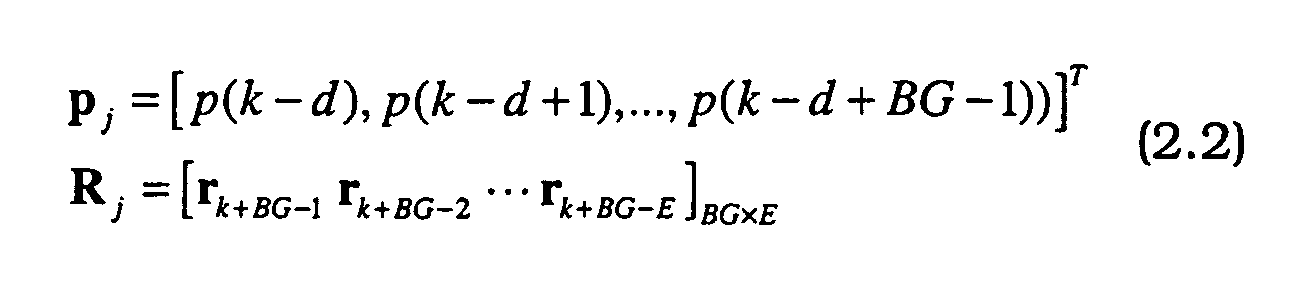
- Here, p(k) denotes the pilot chip at time k, and 0≤d≤E-1 is a delay that a system designer is free to choose. The error at the j-th update is defined as,
- This basic procedure can be extended to MIMO channels. A separate equalizer is used for each of the M transmitters (nothing is gained by a "joint" procedure that uses all M pilots simultaneously). The N FIR filters (one per receive antenna) making the equalizer are,
- To derive the new FLMS-G procedure according to the present invention for SISO channels, note that the terms R H / j p j and R j w j correspond to linear convolutions, which may be converted to circular convolutions by "embedding" them in circulant matrices, e.g.,

- The lower left quadrant of this circulant matrix is identical to R j in equation (2.2). The last row of matrix C is obtained from R j beginning in the lower left corner and moving right along the last row, collecting samples in reverse-time order until reaching r (k + BG - 2E). Each higher row of C is the left circular shift of the preceding row.
These linear convolutions may be efficiently implemented by taking the FFT of the first column C (denoted c 1) and computing,
- The symbol ⊙ denotes "element-by-element" multiplication. The "save" output of equation (3.2) corresponds to R j w j . Similar reasoning gives an expression for R H / j p j , however, it is necessary to take the conjugate of the result.
- For frequency-domain equalization according to the present invention, the scalar step-size, µ, in equation (2.3) may be generalized to a diagonal matrix D j whose elements are computed adaptively as,where diag (•) denotes a diagonal matrix, the norm is taken per-element, and β is a forgetting factor set by the system designer based on empirical study (e.g., the forgetting factor may have a value of 0.05). This generalization is responsible for the improved convergence speed of FLMS-G.

- According to one exemplary embodiment, FLMS-G receiver processing of CDMA signals according to the present invention includes the steps of:
- 1) Get new (non-overlapping) input vector, r j .
- 2)

- 3)
y j = FFT(y j ) - 4)
z j =y j .w j - 5) z ' j = IFFT(
z j ), and z j = z ' j (E + 1:2E) - 6) ej = GAp - 〈p j ,z j 〉
- 7)

- 8)

- 10)

- 11)
w j+1 =w j + D jg j - 12) next j, go to 1).
-
- The FLMS-G receiver processing method described above requires 3 FFT operations per update (each of length 2E).
- The extension to MIMO is straightforward, as was shown above for LMS-G. A beneficial simplification results from summing the spatial filters in the frequency-domain, drastically reducing the number of IFFTs needed. Following equation (3.3), the MIMO step size matrix is diagonal, with elements that correspond to the power spectrum of the signals received on each of the N antennas. This will be described in detail in the next section below.
- By analogy to the recursive-least-squares (RLS) algorithm, we can see that the "optimal" step size matrix is the inverse of the complete covariance matrix, R opt =E{
yy H },y =[y T / 1,...,y T / N] T , and this may be approximated by taking only the diagonal elements so the resulting matrix is easy to invert. In the previous sections, the subscript index represented a time index. However, in this section and the equation given below, the subscript index represent an index on the number of receive antennas N. A better approximation results if the cross-spectrum terms are also included, leading to an über-matrix of diagonal matrices as shown in equation 4.1 below.
- The improved step size matrix is then D = µ(ÜD)-1. The structure of the ÜD matrix makes it easy to invert.
- Next, a SISO implementation of FLMS-G will be described with respect to Fig. 1. For purposes of explanation, the same variables as used in the above described equations will be used in this description. As shown, E new chips r j and E old chips r j-1 of a signal received over an antenna (represented as y j = [r j-1 r j ] are converted to the frequency domain by a first converter 10. A first multiplier 12 obtains the product
z j between the received signaly j in the frequency domain and the set of frequency domain weightsw j to produce the equalized received signal in the frequency domain. - A second converter 14 converts the signal
z j to the time domain. A second of the E chips in the time domain dot product serve as the equalized received signal that is output by the equalizer. The inner product or dot product of this equalized received signal and the chips of the known pilot signal for the CDMA system is obtained by a second multiplier 16. The output of the second multiplier 16 results in an estimate of a pilot symbol amplitude from the equalized received signal in the time domain. - A subtractor 18 subtracts the amplitude of the pilot signal GA p from the output of the second multiplier 16. An inverter 20 inverts the output of the subtractor 18 to produce a scalar that represents a difference in amplitude between the estimated pilot symbol amplitude and a known amplitude of the known pilot signal in the CDMA system.
- A third converter 22 obtains the conjugate of the output from the first converter 10, and a fourth converter 24 converts E zero chips and E chips of the known pilot signal to the frequency domain. A third multiplier 26 mixes this frequency domain version of the pilot signal with the conjugate of the output from the first converter 10. The resulting output indicates a direction of an error in the equalization. The output of the inverter 20 provides the magnitude of this error. A fourth multiplier 28 combines the two to obtain the error signal
g j . - A step matrix calculator 30 generates the diagonal matrix D j according to equation 3.3. A fifth multiplier 32 multiplies this diagonal matrix and error signal. This affects the error signal per tone (i.e., frequency), so that the error signal from weak tones may be boosted. An adder 34 adds the output of the fifth multiplier 32 and output of the fifth multiplier delayed by a delay 36 to generate the set of frequency domain weights.
- Next, a MIMO implementation of FLMS-G will be described with respect to Fig. 2. It will be understood that a MIMO system involves transmission of a plurality, M, of signals from one location using multiple transmit antennas, and receipt of these signals using a plurality of receive antennas at a second location. A MIMO system includes a pilot signal for each of the M transmit antennas. Fig. 2 illustrates the structure for receiver processing using one of the pilot signals. As will be appreciated, the structure for converting the received signals to the frequency domain is common for each pilot signal, and the structure for generating and applying the sets of frequency domain weights is duplicated for each of the respective pilot signals. This latter structure also generates equalized output associated with each transmitted signal. Namely, the M equalized outputs have been temporally corrected and spatially separated by this structure to approximate the M transmitted signals.
- The structure for generating and applying the sets of frequency domain weights includes a first set of multipliers 50. Each multiplier in the first set of multipliers 50 multiplies a respective one of the received signals in the frequency domain by a respective set of frequency domain weights. An adder 52 adds the output of each multiplier in the first set of multipliers 50. From the output of the adder 52, the equalized received signal and the magnitude of the error signal are produced in the same manner described above with respect to Fig. 1.
- Each converter in a set of converters 54 obtains the conjugate of a respective received signal in the frequency domain, and a converter 24 converts E zero chips and E chips of the pilot signal associated with this structure to the frequency domain (in this case the pilot signal of the mth transmit antenna). A second set of multipliers 56 mixes this frequency domain version of the pilot signal with each conjugate of the output from the set of converters 54. The resulting outputs each indicate a direction of an error in the equalization. The output of the inverter 20 provides the magnitude of this error. Each multiplier in a third set of multipliers 58 combines the output from a respective one of the third set of multipliers 56 and the output of the inverter 20 to generate an error signal.
- An uber matrix calculator 60 generates a set of power-spectra and cross-power spectra are generated by multiplying all pairs of received frequency-domain inputs and talking time averages (see eqn 4.1 ). The individual spectra are arranged as diagonal matrices, and then an "uber-diagonal" matrix is formed. The uber matrix calculator 60 produces the inverse of the uber-diagonal matrix as the step-size matrix, applies this to a matrix multiplier 62. The matrix multiplier 62 performs matrix multiplication between the step size matrix and the respective error signals. This affects each error signals per tone (i.e., frequency), so that the error signal from weak tones may be boosted. As will be appreciated, the matrix multiplication produces an output vector for each error signal. Each adder in a set of adders 64 adds a respective output from the matrix multiplier 62 and the respective output of the matrix multiplier 62 delayed by a respective delay in a set of delays 66 to generate a set of frequency domain weights.
- The method and apparatuses according to the present invention significantly reduce the complexity of the equalization process by performing operations in the frequency domain. This is particularly true with a MIMO CDMA system. Furthermore, the uber-diagonal matrix of the present invention provides for improved convergence time, again particularly with a MIMO CDMA system.
- The invention being thus described, it will be obvious that the same may be varied in many ways. For example, using FFT operations of length 2E chips and performing the skip/save operation may not be strictly necessary. Instead, only the current E chips of the received signal may be used (with a corresponding decrease in the number of chips in the other operations as well). Such variations are not to be regarded as a departure from the invention, and all such modifications are intended to be included within the scope of the invention.

Claims (10)
- A method of receiver processing of CDMA signals in a CDMA system, comprising:first converting a received signal in the time domain to a received signal in the frequency domain;equalizing the received signal in the frequency domain using a set of frequency domain weights;second converting the equalized received signal in the frequency domain to an equalized received signal in the time domain;adaptively adjusting the set of frequency domain weights at a symbol rate of the received signal in the time domain based on an error signal produced from the received signal in the frequency domain and a frequency domain representation of a known pilot signal of the CDMA system.
- The method of claim 1, wherein the adaptively adjusting step comprises:generating the error signal in the frequency domain to represent a difference of the equalized received signal from the known pilot signal; andapplying a step size matrix to the error signal to generate the set of frequency domain weights, the step size matrix providing a respective amount to adjust each weight of the set of frequency domain weights based on a spectrum of received signal in the frequency domain.
- The method of claim 2, wherein the generating step comprises:estimating a pilot symbol amplitude from the equalized received signal in the time domain;determining a difference in amplitude between the estimated pilot symbol amplitude and a known amplitude of the known pilot signal as an error magnitude;multiplying the received signal in the frequency domain by the known pilot signal in the frequency domain to obtain an error direction; andmultiplying the error magnitude and the error direction to obtain the error signal.
- The method of claim 3, further comprising:where r is the received signal in the time domain, diag (•) denotes a diagonal matrix, and β is a forgetting factor constant.determining the step size matrix according to the following expression,

- The method of claim 2, further comprising:where r is the received signal in the time domain, diag (•) denotes a diagonal matrix, and β is a forgetting factor constant.determining the step size matrix according to the following expression,

- The method of claim 1, wherein
the first converting step converts a vector yj of a received signal rj and the previous received signal rj-1 where y j =[r j-1 r j ], each of the received signal rj and the previous received signal rj-1 having E elements;
the equalizing step calculates a product of the vector yj and the set of weights to generate a vector z having 2E elements; and
the second converting step converts a second E of the 2E elements in the vector z to the time domain. - The method of claim 1, wherein
the CDMA system is a multiple-input multiple-output (MIMO) CDMA system having a known pilot signal associated with each transmit antenna;
the first converting step converts a plurality of received signals in the time domain to received signals in the frequency domain; and for each known pilot signal,
the equalizing step equalizes the received signals in the frequency domain using a set of frequency domain weights associated with each received signal; and the method further includes,
combining the equalized received signals; and wherein
the second converting step converts the combined equalized received signal in the frequency domain to a combined equalized received signal in the time domain; and
the adaptively adjusting step adaptively adjusts the set of frequency domain weights associated with each received signal at a symbol rate of the received signal in the time domain based on an error signal produced from the received signal in the frequency domain and a frequency domain representation of the known pilot signal. - The method of claim 10, wherein, for each known pilot signal, the adaptively adjusting step comprises:generating the error signal associated with each received signal; andapplying a step size matrix to the error signal to generate the set of frequency domain weights, the step size matrix providing a respective amount to adjust each weight of the set of frequency domain weights based on a spectrum of received signal in the frequency domain.
- The method of claim 11, wherein the applying step comprises:wheredetermining the step size matrix D as,

y = FFT(y j ), y j =[r j-1 r j ] rj is a current received signal in the time domain and rj-1 is a previous received signal in the time domain, diag (•) denotes a diagonal matrix, and β is a forgetting factor constant. - A method of receiver processing of CDMA signals in a CDMA system, comprising:applying an LMS (least mean squares) algorithm to a received CDMA signal in the frequency domain where weights of the LMS algorithm are updated in the frequency domain at a symbol rate of the received CDMA signal.
Applications Claiming Priority (2)
| Application Number | Priority Date | Filing Date | Title |
|---|---|---|---|
| US10/872,359 US7660340B2 (en) | 2004-06-22 | 2004-06-22 | Method of receiver processing of CDMA signals in a CDMA system |
| US872359 | 2004-06-22 |
Publications (2)
| Publication Number | Publication Date |
|---|---|
| EP1610513A1 true EP1610513A1 (en) | 2005-12-28 |
| EP1610513B1 EP1610513B1 (en) | 2008-03-12 |
Family
ID=34941689
Family Applications (1)
| Application Number | Title | Priority Date | Filing Date |
|---|---|---|---|
| EP05253701A Expired - Fee Related EP1610513B1 (en) | 2004-06-22 | 2005-06-15 | Adaptive frequency domain equalization of a CDMA signal |
Country Status (6)
| Country | Link |
|---|---|
| US (1) | US7660340B2 (en) |
| EP (1) | EP1610513B1 (en) |
| JP (1) | JP4990510B2 (en) |
| KR (1) | KR101073821B1 (en) |
| CN (1) | CN1713553B (en) |
| DE (1) | DE602005005245T2 (en) |
Cited By (2)
| Publication number | Priority date | Publication date | Assignee | Title |
|---|---|---|---|---|
| US7920661B2 (en) | 2006-03-21 | 2011-04-05 | Qualcomm Incorporated | Decision feedback equalizer for code division multiplexed signals |
| CN110048750A (en) * | 2018-09-29 | 2019-07-23 | 中国传媒大学 | A kind of half blind receiver based on optimization LM algorithm |
Families Citing this family (5)
| Publication number | Priority date | Publication date | Assignee | Title |
|---|---|---|---|---|
| US7492815B2 (en) * | 2004-11-24 | 2009-02-17 | Nokia Corporation | Reduced parallel and pipelined high-order MIMO LMMSE receiver architecture |
| US7483480B2 (en) * | 2004-11-24 | 2009-01-27 | Nokia Corporation | FFT accelerated iterative MIMO equalizer receiver architecture |
| CN103297371B (en) | 2006-02-08 | 2018-01-16 | 联想创新有限公司(香港) | Single carrier transmitting system, communicator and for single carrier transmission method therein |
| JP4616196B2 (en) * | 2006-03-07 | 2011-01-19 | ティーオーエー株式会社 | Unknown system identification system and method |
| CN102006144B (en) * | 2009-09-01 | 2014-01-08 | 华为技术有限公司 | Precoding method and device as well as frequency domain balancing method and device |
Citations (2)
| Publication number | Priority date | Publication date | Assignee | Title |
|---|---|---|---|---|
| US20010033614A1 (en) * | 2000-01-20 | 2001-10-25 | Hudson John E. | Equaliser for digital communications systems and method of equalisation |
| EP1289182A2 (en) * | 2001-08-24 | 2003-03-05 | Lucent Technologies Inc. | Signal detection by a receiver in a multiple antenna time-dispersive system |
Family Cites Families (17)
| Publication number | Priority date | Publication date | Assignee | Title |
|---|---|---|---|---|
| US4658426A (en) * | 1985-10-10 | 1987-04-14 | Harold Antin | Adaptive noise suppressor |
| US4939685A (en) * | 1986-06-05 | 1990-07-03 | Hughes Aircraft Company | Normalized frequency domain LMS adaptive filter |
| US5481570A (en) * | 1993-10-20 | 1996-01-02 | At&T Corp. | Block radio and adaptive arrays for wireless systems |
| US6535552B1 (en) * | 1999-05-19 | 2003-03-18 | Motorola, Inc. | Fast training of equalizers in discrete multi-tone (DMT) systems |
| JP2001313594A (en) * | 2000-04-28 | 2001-11-09 | Fujitsu Ltd | Method for updating coefficient of time domain equalizer for dmt system, receive method, dmt system and dmt modem |
| US6912258B2 (en) * | 2000-07-07 | 2005-06-28 | Koninklijke Philips Electtronics N.V. | Frequency-domain equalizer for terrestrial digital TV reception |
| EP1332613A1 (en) * | 2000-10-17 | 2003-08-06 | Koninklijke Philips Electronics N.V. | Multi-standard channel decoder |
| US20020086707A1 (en) * | 2000-11-15 | 2002-07-04 | Struhsaker Paul F. | Wireless communication system using block filtering and fast equalization-demodulation and method of operation |
| CN1224228C (en) * | 2001-02-22 | 2005-10-19 | 皇家菲利浦电子有限公司 | Multicarrier transmission system using multiplication by leakage matrix with complex reduction |
| US7042937B2 (en) * | 2001-04-23 | 2006-05-09 | Koninklijke Philips Electronics N.V. | Hybrid frequency-time domain equalizer |
| CN1134923C (en) * | 2001-07-18 | 2004-01-14 | 华为技术有限公司 | Time-space joined multi-path search method for CDMA communication system |
| US7212569B1 (en) * | 2002-06-28 | 2007-05-01 | At&T Corp. | Frequency domain decision feedback equalizer |
| KR100448633B1 (en) * | 2002-10-22 | 2004-09-13 | 한국전자통신연구원 | Residual freqency offset tracking scheme for single carrier - freuqency domian equalizer system and method thereof |
| US20040142665A1 (en) * | 2003-01-21 | 2004-07-22 | Apostolos Papathanasion | Method and apparatus for diversity combining using a least squares approach |
| US7586982B2 (en) * | 2003-05-06 | 2009-09-08 | Nokia Corporation | Kalman filter based method and apparatus for linear equalization of CDMA downlink channels |
| US6873596B2 (en) * | 2003-05-13 | 2005-03-29 | Nokia Corporation | Fourier-transform based linear equalization for CDMA downlink |
| US7110352B2 (en) * | 2003-12-09 | 2006-09-19 | Nokia Corporation | Direct-sequence CDMA method and device |
-
2004
- 2004-06-22 US US10/872,359 patent/US7660340B2/en not_active Expired - Fee Related
-
2005
- 2005-06-15 EP EP05253701A patent/EP1610513B1/en not_active Expired - Fee Related
- 2005-06-15 DE DE602005005245T patent/DE602005005245T2/en active Active
- 2005-06-17 KR KR1020050052234A patent/KR101073821B1/en not_active IP Right Cessation
- 2005-06-22 CN CN2005100790646A patent/CN1713553B/en not_active Expired - Fee Related
- 2005-06-22 JP JP2005181605A patent/JP4990510B2/en not_active Expired - Fee Related
Patent Citations (2)
| Publication number | Priority date | Publication date | Assignee | Title |
|---|---|---|---|---|
| US20010033614A1 (en) * | 2000-01-20 | 2001-10-25 | Hudson John E. | Equaliser for digital communications systems and method of equalisation |
| EP1289182A2 (en) * | 2001-08-24 | 2003-03-05 | Lucent Technologies Inc. | Signal detection by a receiver in a multiple antenna time-dispersive system |
Non-Patent Citations (5)
| Title |
|---|
| BURG A ET AL INSTITUTE OF ELECTRICAL AND ELECTRONICS ENGINEERS: "Practical low complexity linear equalization for MIMO-CDMA systems", CONFERENCE RECORD OF THE 37TH. ASILOMAR CONFERENCE ON SIGNALS, SYSTEMS, & COMPUTERS. PACIFIC GROOVE, CA, NOV. 9 - 12, 2003, ASILOMAR CONFERENCE ON SIGNALS, SYSTEMS AND COMPUTERS, NEW YORK, NY : IEEE, US, vol. VOL. 1 OF 2. CONF. 37, 9 November 2003 (2003-11-09), pages 1266 - 1272, XP010701674, ISBN: 0-7803-8104-1 * |
| CLARK M V: "Adaptive frequency-domain equalization and diversity combining for broadband wireless communications", VEHICULAR TECHNOLOGY CONFERENCE, 1998. VTC 98. 48TH IEEE OTTAWA, ONT., CANADA 18-21 MAY 1998, NEW YORK, NY, USA,IEEE, US, vol. 1, 18 May 1998 (1998-05-18), pages 409 - 413, XP010287837, ISBN: 0-7803-4320-4 * |
| DMOCHOWSKI P A ET AL: "Frequency domain equalization for high data rate multipath channels", 2001 IEEE PACIFIC RIM CONFERENCE ON COMMUNICATIONS, COMPUTERS AND SIGNAL PROCESSING. VICTORIA, BC, CANADA, AUG. 26 - 28, 2001, IEEE PACIFIC RIM CONFERENCE ON COMMUNICATIONS, COMPUTERS AND SIGNAL PROCESSING. PACRIM, NEW YORK, NY : IEEE, US, vol. VOL. 1 OF 2. CONF. 8, 26 August 2001 (2001-08-26), pages 534 - 537, XP010560408, ISBN: 0-7803-7080-5 * |
| MAILAENDER L: "Adaptive frequency-domain chip equalization for the MIMO CDMA downlink", VEHICULAR TECHNOLOGY CONFERENCE, 2004. VTC2004-FALL. 2004 IEEE 60TH LOS ANGELES, CA, USA 26-29 SEPT. 2004, PISCATAWAY, NJ, USA,IEEE, 26 September 2004 (2004-09-26), pages 1766 - 1770, XP010786940, ISBN: 0-7803-8521-7 * |
| MAILAENDER L: "Linear MIMO chip equalization for the CDMA downlink", SIGNAL PROCESSING ADVANCES IN WIRELESS COMMUNICATIONS, 2003. SPAWC 2003. 4TH IEEE WORKSHOP ON ROME, ITALY 15-18 JUNE 2003, PISCATAWAY, NJ, USA,IEEE, US, 15 June 2003 (2003-06-15), pages 299 - 303, XP010713482, ISBN: 0-7803-7858-X * |
Cited By (3)
| Publication number | Priority date | Publication date | Assignee | Title |
|---|---|---|---|---|
| US7920661B2 (en) | 2006-03-21 | 2011-04-05 | Qualcomm Incorporated | Decision feedback equalizer for code division multiplexed signals |
| CN110048750A (en) * | 2018-09-29 | 2019-07-23 | 中国传媒大学 | A kind of half blind receiver based on optimization LM algorithm |
| CN110048750B (en) * | 2018-09-29 | 2021-07-20 | 中国传媒大学 | Half-blind receiver based on optimized LM algorithm |
Also Published As
| Publication number | Publication date |
|---|---|
| US20050281323A1 (en) | 2005-12-22 |
| JP4990510B2 (en) | 2012-08-01 |
| US7660340B2 (en) | 2010-02-09 |
| CN1713553B (en) | 2012-12-26 |
| JP2006014324A (en) | 2006-01-12 |
| CN1713553A (en) | 2005-12-28 |
| KR101073821B1 (en) | 2011-10-17 |
| EP1610513B1 (en) | 2008-03-12 |
| KR20060046474A (en) | 2006-05-17 |
| DE602005005245T2 (en) | 2009-03-12 |
| DE602005005245D1 (en) | 2008-04-24 |
Similar Documents
| Publication | Publication Date | Title |
|---|---|---|
| EP0961416B1 (en) | Adaptive array transceiver | |
| KR100317518B1 (en) | Detectors for cdma systems | |
| EP1776818B1 (en) | Method for equalizing a digital signal and equalizer | |
| US7466750B2 (en) | Apparatus for channel equalization using multi antenna and method thereof | |
| EP1610513B1 (en) | Adaptive frequency domain equalization of a CDMA signal | |
| US8861572B2 (en) | Method and arrangement of delay spread compensation | |
| US5796788A (en) | Method and apparatus for interference decorrelation in time and space | |
| US20060199557A1 (en) | MIMO receiver, MIMO reception method and wireless communication system | |
| GB2414147A (en) | Equaliser comprising a first filter for adapting filter coefficients and a second filter for equalising data using the adapted coefficients | |
| US20050117532A1 (en) | Fourier-transform based linear equalization for CDMA downlink | |
| US20040142665A1 (en) | Method and apparatus for diversity combining using a least squares approach | |
| JP2008511219A (en) | Precoder and method for reordering input sequences to obtain transmission sequences | |
| EP1563657B1 (en) | Transform-domain sample-by-sample decision feedback equalizer | |
| JPH11289213A (en) | Adaptive receiver | |
| WO2007114478A1 (en) | Receiver | |
| Al-Fuhaidi et al. | Interference cancellation with space diversity for downlink MC-CDMA systems | |
| US8422607B2 (en) | Generating channel estimates in a radio receiver | |
| JP7264260B2 (en) | Wireless communication system, wireless communication method, transmitting station device and receiving station device | |
| KR100430524B1 (en) | Orthogonal Frequency Division Multiplexing Receiving System Using Adaptive Array Antennas And Method Thereof | |
| KR100843252B1 (en) | Iterative reception method and Iterative receiver | |
| JP4463747B2 (en) | Interference signal reduction circuit | |
| Simon et al. | Adaptive multipath channel estimation in CDMA based on prefiltering and combination with a linear equalizer | |
| WO2003077440A1 (en) | Adaptive antenna receiver and its receiving method | |
| Mailaender | Adaptive frequency-domain chip equalization for the MIMO CDMA downlink | |
| JPWO2008093490A1 (en) | Communication path equalization apparatus and method |
Legal Events
| Date | Code | Title | Description |
|---|---|---|---|
| PUAI | Public reference made under article 153(3) epc to a published international application that has entered the european phase |
Free format text: ORIGINAL CODE: 0009012 |
|
| 17P | Request for examination filed |
Effective date: 20050625 |
|
| AK | Designated contracting states |
Kind code of ref document: A1 Designated state(s): AT BE BG CH CY CZ DE DK EE ES FI FR GB GR HU IE IS IT LI LT LU MC NL PL PT RO SE SI SK TR |
|
| AX | Request for extension of the european patent |
Extension state: AL BA HR LV MK YU |
|
| AKX | Designation fees paid |
Designated state(s): DE FR GB |
|
| 17Q | First examination report despatched |
Effective date: 20060508 |
|
| GRAP | Despatch of communication of intention to grant a patent |
Free format text: ORIGINAL CODE: EPIDOSNIGR1 |
|
| GRAS | Grant fee paid |
Free format text: ORIGINAL CODE: EPIDOSNIGR3 |
|
| GRAA | (expected) grant |
Free format text: ORIGINAL CODE: 0009210 |
|
| AK | Designated contracting states |
Kind code of ref document: B1 Designated state(s): DE FR GB |
|
| REG | Reference to a national code |
Ref country code: GB Ref legal event code: FG4D |
|
| REF | Corresponds to: |
Ref document number: 602005005245 Country of ref document: DE Date of ref document: 20080424 Kind code of ref document: P |
|
| ET | Fr: translation filed | ||
| PLBE | No opposition filed within time limit |
Free format text: ORIGINAL CODE: 0009261 |
|
| STAA | Information on the status of an ep patent application or granted ep patent |
Free format text: STATUS: NO OPPOSITION FILED WITHIN TIME LIMIT |
|
| 26N | No opposition filed |
Effective date: 20081215 |
|
| REG | Reference to a national code |
Ref country code: GB Ref legal event code: 732E Free format text: REGISTERED BETWEEN 20131031 AND 20131106 |
|
| REG | Reference to a national code |
Ref country code: FR Ref legal event code: CD Owner name: ALCATEL-LUCENT USA INC. Effective date: 20131122 |
|
| REG | Reference to a national code |
Ref country code: FR Ref legal event code: GC Effective date: 20140410 |
|
| REG | Reference to a national code |
Ref country code: FR Ref legal event code: RG Effective date: 20141015 |
|
| REG | Reference to a national code |
Ref country code: FR Ref legal event code: PLFP Year of fee payment: 11 |
|
| PGFP | Annual fee paid to national office [announced via postgrant information from national office to epo] |
Ref country code: DE Payment date: 20150629 Year of fee payment: 11 Ref country code: GB Payment date: 20150629 Year of fee payment: 11 |
|
| PGFP | Annual fee paid to national office [announced via postgrant information from national office to epo] |
Ref country code: FR Payment date: 20150617 Year of fee payment: 11 |
|
| REG | Reference to a national code |
Ref country code: DE Ref legal event code: R119 Ref document number: 602005005245 Country of ref document: DE |
|
| GBPC | Gb: european patent ceased through non-payment of renewal fee |
Effective date: 20160615 |
|
| REG | Reference to a national code |
Ref country code: FR Ref legal event code: ST Effective date: 20170228 |
|
| PG25 | Lapsed in a contracting state [announced via postgrant information from national office to epo] |
Ref country code: DE Free format text: LAPSE BECAUSE OF NON-PAYMENT OF DUE FEES Effective date: 20170103 Ref country code: FR Free format text: LAPSE BECAUSE OF NON-PAYMENT OF DUE FEES Effective date: 20160630 |
|
| PG25 | Lapsed in a contracting state [announced via postgrant information from national office to epo] |
Ref country code: GB Free format text: LAPSE BECAUSE OF NON-PAYMENT OF DUE FEES Effective date: 20160615 |