EP1610443A1 - Permanent magnet rotor - Google Patents
Permanent magnet rotor Download PDFInfo
- Publication number
- EP1610443A1 EP1610443A1 EP05013381A EP05013381A EP1610443A1 EP 1610443 A1 EP1610443 A1 EP 1610443A1 EP 05013381 A EP05013381 A EP 05013381A EP 05013381 A EP05013381 A EP 05013381A EP 1610443 A1 EP1610443 A1 EP 1610443A1
- Authority
- EP
- European Patent Office
- Prior art keywords
- magnet
- end plates
- motor
- pair
- rotor
- Prior art date
- Legal status (The legal status is an assumption and is not a legal conclusion. Google has not performed a legal analysis and makes no representation as to the accuracy of the status listed.)
- Withdrawn
Links
Images




Classifications
-
- H—ELECTRICITY
- H02—GENERATION; CONVERSION OR DISTRIBUTION OF ELECTRIC POWER
- H02K—DYNAMO-ELECTRIC MACHINES
- H02K1/00—Details of the magnetic circuit
- H02K1/06—Details of the magnetic circuit characterised by the shape, form or construction
- H02K1/22—Rotating parts of the magnetic circuit
- H02K1/27—Rotor cores with permanent magnets
- H02K1/2706—Inner rotors
-
- H—ELECTRICITY
- H02—GENERATION; CONVERSION OR DISTRIBUTION OF ELECTRIC POWER
- H02K—DYNAMO-ELECTRIC MACHINES
- H02K1/00—Details of the magnetic circuit
- H02K1/06—Details of the magnetic circuit characterised by the shape, form or construction
- H02K1/22—Rotating parts of the magnetic circuit
- H02K1/27—Rotor cores with permanent magnets
-
- H—ELECTRICITY
- H02—GENERATION; CONVERSION OR DISTRIBUTION OF ELECTRIC POWER
- H02K—DYNAMO-ELECTRIC MACHINES
- H02K1/00—Details of the magnetic circuit
- H02K1/06—Details of the magnetic circuit characterised by the shape, form or construction
- H02K1/22—Rotating parts of the magnetic circuit
- H02K1/27—Rotor cores with permanent magnets
- H02K1/2706—Inner rotors
- H02K1/2713—Inner rotors the magnetisation axis of the magnets being axial, e.g. claw-pole type
-
- H—ELECTRICITY
- H02—GENERATION; CONVERSION OR DISTRIBUTION OF ELECTRIC POWER
- H02K—DYNAMO-ELECTRIC MACHINES
- H02K1/00—Details of the magnetic circuit
- H02K1/06—Details of the magnetic circuit characterised by the shape, form or construction
- H02K1/22—Rotating parts of the magnetic circuit
- H02K1/27—Rotor cores with permanent magnets
- H02K1/2706—Inner rotors
- H02K1/272—Inner rotors the magnetisation axis of the magnets being perpendicular to the rotor axis
- H02K1/274—Inner rotors the magnetisation axis of the magnets being perpendicular to the rotor axis the rotor consisting of two or more circumferentially positioned magnets
- H02K1/2753—Inner rotors the magnetisation axis of the magnets being perpendicular to the rotor axis the rotor consisting of two or more circumferentially positioned magnets the rotor consisting of magnets or groups of magnets arranged with alternating polarity
- H02K1/276—Magnets embedded in the magnetic core, e.g. interior permanent magnets [IPM]
- H02K1/2766—Magnets embedded in the magnetic core, e.g. interior permanent magnets [IPM] having a flux concentration effect
Definitions
- This invention generally relates to an interior permanent magnetic motor (IPM motor), especially to how to implant a magnet into a rotor structure for high efficiency.
- IPM motor interior permanent magnetic motor
- a brushless motor having a rotor, which is embedded, therein, with plural permanent magnets, arranged in place at a predetermined distance relative to an inner periphery of a stator, of which a stator core is wound with coils, has been widely applied to an electric vehicle.
- a stator core is of cylindrical structure and is integrally formed with plural teeth protruding in a radially inner direction from an outer periphery thereof. These plural teeth are wound with coils. Portions of each coil, which appear axially outwardly from ends of the stator core, are, in general, referred to as coil ends.
- a rotor is formed in such a manner that a rotor core, which is attached, therein, with plural permanent magnets, is integrally equipped to a shaft, and is inserted into an inner side of the stator with the windings so as to be seated therein.
- the rotor rotates in response to electromagnetic force that is generated by electrically exciting the stator windings, as needed.
- a rotor 120 is equipped with a rotor core 121, permanent magnets 122, a pair of end plates 123, a shaft 124 and rivets 125.
- the rotor core 121 is a laminated body which is formed with plural core plates 126 that are layered.
- the rotor core 121 is held, at both axial ends thereof, by the pair of end plates 123, and is integrally fixed to the end plates 123 by means of the plural rivets 125.
- the core plates 126 each has a penetrating hole 126a, which is defined at a central portion of each core plate 126 and is employed for inserting the shaft 124 thereinto, plural penetrating holes 126b, which are defined at an outer peripheral side of the penetrating hole 126a and are employed for the plural rivets 125, and plural penetrating holes 126c, which are defined at a further outer peripheral side of the penetrating holes 126b and are employed for attaching the plural permanent magnets 122 thereinto.
- the respective permanent magnets 122 are inserted into the plural penetrating holes 126c and are fixed thereto.
- Each of the pair of end plates 123 has a penetrating hole 123a, which is defined at a central portion thereof and is employed for inserting the shaft 124 thereinto, and plural penetrating holes 123b, which are defined at an outer peripheral side of the penetrating hole 123a and are employed for the plural rivets 125.
- the respective rivets 125 are inserted into the plural penetrating holes 123b of the pair of end plates 123 and the plural penetrating holes 126b of the core plates 126. Both ends of the respective rivets 125, which appear axially outwardly from the end plates 123, are caulked.
- a running torque is generated by electrically exciting, in a vertically sectional direction of a rotational axis, a stator core 111, the rotor core 121 and the permanent magnets 122. That is, a magnetic field, which generates a running torque, is not effectively applied to spaces axially defined between coil ends 112a and the end plates 123. Therefore, In this type of conventional brushless motor, these spaces have not effectively contributed to generation of a running torque. As a result, an axial length of the motor is extended in response to a thickness (an axial length) of the coil ends 122a, or of the end plates 123. Moreover, the end plates 123 hold the permanent magnets 122 in an axial direction, the magnets 122 which have been housed in the rotor core 121.
- the present invention has been made in view of the above circumstances, and provides a motor of which axial length can be abbreviated. Further, the present invention provides a motor which enables increasing in a degree of torque.
- a motor includes: a rotor; a rotor core included in the rotor, the rotor core included in the rotor, the rotor core which is configured to be built, thereinto, with at least one first magnet; and a pair of end plates, one of which is positioned at an axial end of the motor, the other one of which is positioned at the other axial end of the motor.
- the pair of end plates holds the rotor core at axial ends of the rotor core.
- the motor further includes at least one second magnet built into the pair of end plates and capable of producing magnetic fluxes in an axial direction of the motor.
- the at least one second magnet is positioned so as to be in contact with the at least one first magnet.
- the at least one second magnet is positioned so as to be in contact with a portion of the rotor core which is positioned at a radially outer side of the at least one first magnet.
- a number of poles of the at least one second magnet at each of the pair of end plates is equal to a number of poles of the at least one first magnet, and a polarity of the second magnet at a side of the rotor core is identical to a polarity at an outer peripheral side of the at least one first magnet.
- a portion of the pair of end plates, which is axially opposite to a side of the rotor has a soft magnetic material, and at least a portion of the pair of end plates, which corresponds to the at least one first magnet, has a nonmagnetic portion.
- a motor according to a first embodiment of the present invention is a brushless motor, which has a stator 10 (a non-rotating armature), a rotor 20 and a casing 30.
- the stator 10 is, as a whole, of an annular shape, or of a cylindrical shape, and mainly consists of a stator core 11 and coils 12.
- the stator core 11 is a stacked lamination with plural stator steel plates (not illustrated) which are formed by punching silicon steel plates, and is caulked.
- the stator core 11 is integrally formed with eight teeth 11b which protrude radially inwardly from an outer periphery 11a of the stator core 11, as is illustrated in Fig. 2.
- Slots 11c are defined between the respective neighboring teeth 11b. According to the first embodiment of the present invention, there are eight teeth 11b and eight slots 11c incorporated into the stator core 11. The shape, and the number, of each are not limited to the above, and can be designed as required. Further, according to the first embodiment of the present invention, the stator core 11 is a stacked lamination with plural stator steel plates, but the stator core 11 can be a steel product, or can be made of a sintered metal.
- the teeth11b are respectively wound with coils 12 which are inserted into the slots 11c. Portions of the coils 12, which appear axially outwardly from the stator core 11, are coil ends 12a. One tip ends of the coils 12 are connected to terminals (not illustrated) which are provided so as to supply electric current from an exterior source to the windings 12.
- the stator core 11, the coils 12 and the terminal can be molded with an isolative sealing material (not illustrated).
- an insulator (not illustrated) having heat conduction can be provided at each air gap between the respective teeth 11b and the respective windings 12.
- Coil wires for the coils 12 can be coated wires and are wound at the teeth 11b atrequired wire turns.
- a material for the coil wire can be a conducting material such as copper, aluminum, and brass, as non-limiting examples.
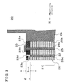
- the rotor 20 mainly consists of a rotor core 21, which is attached, therein, with plural permanent magnets 22 (at least one first magnet), and a shaft 24, which is integrally equipped with the rotor core 21.
- the rotor 20 is inserted into an inner side of the stator 10 with an air gap relative to an inner periphery of the stator 10.
- the rotor 20 includes the rotor core 21, the permanent magnets 22, a pair of end plates 23, a shaft 24 and plural rivets 25.
- the rotor core 21 is a stacked lamination with plural core plates 26.
- the rotor core 21 is held, at both axial ends thereof, by the pair of end plates 23, and is integrally fixed to the pair of end plates 23 by the plural rivets 25.
- the core plates 26 respectively include a penetrating hole 26a, which is defined at a central portion of the respective core plates 26 and is employed for inserting the shaft 24 thereinto, and plural penetrating holes 26b, which are defined at a radially outer side of the penetrating hole 26a and are employed for the rivets 25, and plural penetrating holes 26c, which are defined at a radially outer side of the penetrating hole 26b and are employed for the permanent magnets 22.
- airgaps 26d are defined within a range that is not filled with the permanent magnets 22, and at both ends of each permanent magnet 22. These permanent magnets 22 are inserted into the penetrating holes 26c of the core plates 26 so as to be seated therein.
- Each of the end plates 23 includes a penetrating hole 23a, which is defined at a central portion of each end plate 23 and is employed for inserting the shaft 24 thereinto, and plural penetrating holes 23b, which are defined at a radially outer side of the penetrating hole 23a and is employed for the rivets 25.
- Each of the end plates 23 is moreover embedded, therein, with plural permanent magnets 23c (at least one second magnet) at a side of the rotor core 21.
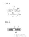
- An area of the end plates 23, the area into which the permanent magnets 23c are not inserted into, is made of a soft magnetic material (e.g., an iron). It is preferable that a thickness, or an axial length, of each end plate 23 is designed to an extent at which DC magnetic saturation does not occur due to magnetic flux of the permanent magnets 23c; as is summarized in Fig. 5.
- Airgaps 23d are defined between inner peripheral surfaces of the magnets 23c and soft magnetic material portions of the end plates 23, the airgaps 23d which serve as nonmagnetic portions. The airgaps 23d serve so as to prevent magnetic flux of the permanent magnets 22 from leaking.
- air gaps 23d are defined so as to include axial end surfaces of the permanent magnets 22, the axial end surfaces which exclude areas in which the peixnanent magnets 22 are in contact with the permanent magnets 23c, as is illustrated in Figs. 3 to 7.
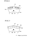
- Each permanent magnet 23c is positioned so as to contact with a portion of the rotor core 21 which is positioned at a radially outer side of the magnet 22. Further, a portion of each permanent magnet 23c is positioned at a radially outer side of the permanent magnet 22, as is illustrated in Figs. 3 to 6.
- the permanent magnets 23c are axially magnetized. Regarding the end plate 23 at one side, the number of poles of the permanent magnets 23c is equal to the number of poles of the permanent magnets 22.
- the polarity of the respective permanent magnets 23c at the rotor core 21 side is identical to the polarity at an outer peripheral side of the respective corresponding permanent magnets 22.
- the magnets 23c are magnetized in a direction towards the permanent magnets 22, while, while the permanent magnets 22 are magnetized in a radially inner direction, the magnets 23c are magnetized in a direction which is opposite to the permanent magnets 22, as is illustrated in Figs. 3, 6, and 7.
- the shaft 24 is freely rotatably supported by a pair of plates 31 via ball bearings 32.
- the rivets 25 are respectively inserted into the penetrating holes 23b of the end plates 23 and the penetrating holes 26b of the core plates 26. Portions of the rivets 25 which appear axially outwardly from the end plates 23 are caulked.
- the casing 30 is of a cylindrical shaped structure and surrounds an outer periphery of the stator 10, and includes the pair of plates 31 at both axial ends thereof.
- Fig. 8 shows a result obtained by a finite element method called "FEM" for the analysis of magnetic fields.
- the first embodiment of the present invention it is possible to prevent magnetic fluxes generated from the permanent magnets 22, which are embedded into the rotor core 21, from leaking, and is possible to add magnetic fluxes of the permanent magnets 23c to the permanent magnets 22. Therefore, it is possible to increase a degree of motor torque.
- an end plate which did not contribute to torque generation in a conventional motor, can contribute to torque generation. Therefore, it is possible to reduce the laminated thickness of the rotor core 21, thereby enabling to abbreviate an axial length of a motor.
- a structure of an end plate of a motor according to the second embodiment of the present invention is different from the aforementioned structure of the end plates 23 of the motor according to the first embodiment.
- An area of the end plates 23, the area which is not inserted with the magnets 23c, is made of two types of materials; one at the side of the rotor core 21 is a nonmagnetic material portion 23f, which is made of a nonmagnetic material, e.g.
- a soft magnetic material portion 23e which is made of a soft magnetic material, e.g. an iron, as illustrated in Fig. 9. It is preferable that a thickness of the soft magnetic material portion 23e is designed at an extent at which DC magnetic saturation is not generated due to magnetic fluxes of the magnets 23c, as is illustrated in Fig. 12.
- the airgaps 23d of the end plates 23 of the motor according to the first embodiment are changed to the nonmagnetic material portions 23d, in order to prevent magnetic fluxes of the magnets 22 from leaking.
- the other structure of the motor according to the second embodiment, apart from the nonmagnetic material portion 23f, is the same as the one of the motor according to the first embodiment. Therefore, the same effect as the first embodiment can be generated.
- a motor according to a third embodiment of the present invention As a soft magnetic material portion (a portion which is not inserted with the magnets 23c out of the end plates 23 in Fig. 3), a powder core is adapted in the end plates 23 of the motor according to the second embodiment.
- this powder core is formed by compressing a magnetic powder applied with insulation.
- a magnetic material is employed for the end plates 23, a magnetic flux density of the end plates 23 are enhanced, thereby increasing an iron loss at the end plates 23. Therefore, comparing with a normal iron, because a powder core is an insulated lamination, it is possible to restrain increase in an iron loss. Therefore, according to the third embodiment of the present invention, it is possible to restrain increase in an iron loss at the end plates 23.
- the permanent magnets (23c in Fig. 6 and 23c in Fig. 13) are formed to be of approximately wedge-shaped, and the end plates (23 in Figs. 6 and 13) is provided with a housing portion of which shape corresponds to the wedge-shaped structure of each permanent magnet 23. Therefore, the permanent magnets 23c can be fitted into the end plates from an axial direction so as to be seated therein.
- an outer diameter of each end plate is equal to or less than the outer diameter of the rotor core, thereby facilitating assembling of the rotor already being equipped with the end plates to the stator, According to the fourth embodiment of the present invention, a size-up preventing ring, which increases an outer diameter of the end plates, is not necessary, thereby enabling to extend a radial position of the permanent magnets 23 in a radially outward direction.
- the pair of end plates 23 can contribute to torque generation. Further, it is possible to reduce a thickness of the rotor core 21 and hence to abbreviate an axial length of the motor.
Landscapes
- Engineering & Computer Science (AREA)
- Power Engineering (AREA)
- Permanent Field Magnets Of Synchronous Machinery (AREA)
- Iron Core Of Rotating Electric Machines (AREA)
- Permanent Magnet Type Synchronous Machine (AREA)
Abstract
Description
- This invention generally relates to an interior permanent magnetic motor (IPM motor), especially to how to implant a magnet into a rotor structure for high efficiency.
- In recent technologies, a brushless motor having a rotor, which is embedded, therein, with plural permanent magnets, arranged in place at a predetermined distance relative to an inner periphery of a stator, of which a stator core is wound with coils, has been widely applied to an electric vehicle. A stator core is of cylindrical structure and is integrally formed with plural teeth protruding in a radially inner direction from an outer periphery thereof. These plural teeth are wound with coils. Portions of each coil, which appear axially outwardly from ends of the stator core, are, in general, referred to as coil ends. A rotor is formed in such a manner that a rotor core, which is attached, therein, with plural permanent magnets, is integrally equipped to a shaft, and is inserted into an inner side of the stator with the windings so as to be seated therein. The rotor rotates in response to electromagnetic force that is generated by electrically exciting the stator windings, as needed.
- This type of conventional brushless motor is disclosed in JP2000-184645A and is described below with reference to Fig. 15. As is clearly illustrated in Fig. 15, a
rotor 120 is equipped with arotor core 121,permanent magnets 122, a pair ofend plates 123, ashaft 124 andrivets 125. Therotor core 121 is a laminated body which is formed withplural core plates 126 that are layered. Therotor core 121 is held, at both axial ends thereof, by the pair ofend plates 123, and is integrally fixed to theend plates 123 by means of theplural rivets 125. Thecore plates 126 each has apenetrating hole 126a, which is defined at a central portion of eachcore plate 126 and is employed for inserting theshaft 124 thereinto, plural penetratingholes 126b, which are defined at an outer peripheral side of the penetratinghole 126a and are employed for theplural rivets 125, and plural penetratingholes 126c, which are defined at a further outer peripheral side of the penetratingholes 126b and are employed for attaching the pluralpermanent magnets 122 thereinto. The respectivepermanent magnets 122 are inserted into the plural penetratingholes 126c and are fixed thereto. Each of the pair ofend plates 123 has apenetrating hole 123a, which is defined at a central portion thereof and is employed for inserting theshaft 124 thereinto, and plural penetratingholes 123b, which are defined at an outer peripheral side of the penetratinghole 123a and are employed for theplural rivets 125. Therespective rivets 125 are inserted into the plural penetratingholes 123b of the pair ofend plates 123 and the plural penetratingholes 126b of thecore plates 126. Both ends of therespective rivets 125, which appear axially outwardly from theend plates 123, are caulked. - In this type of conventional brushless motor, a running torque is generated by electrically exciting, in a vertically sectional direction of a rotational axis, a
stator core 111, therotor core 121 and thepermanent magnets 122. That is, a magnetic field, which generates a running torque, is not effectively applied to spaces axially defined betweencoil ends 112a and theend plates 123. Therefore, In this type of conventional brushless motor, these spaces have not effectively contributed to generation of a running torque. As a result, an axial length of the motor is extended in response to a thickness (an axial length) of the coil ends 122a, or of theend plates 123. Moreover, theend plates 123 hold thepermanent magnets 122 in an axial direction, themagnets 122 which have been housed in therotor core 121. - The present invention has been made in view of the above circumstances, and provides a motor of which axial length can be abbreviated. Further, the present invention provides a motor which enables increasing in a degree of torque.
- According to an aspect of the present invention, a motor includes: a rotor; a rotor core included in the rotor, the rotor core included in the rotor, the rotor core which is configured to be built, thereinto, with at least one first magnet; and a pair of end plates, one of which is positioned at an axial end of the motor, the other one of which is positioned at the other axial end of the motor. The pair of end plates holds the rotor core at axial ends of the rotor core. The motor further includes at least one second magnet built into the pair of end plates and capable of producing magnetic fluxes in an axial direction of the motor.
- It is preferable that the at least one second magnet is positioned so as to be in contact with the at least one first magnet.
- It is further preferable that the at least one second magnet is positioned so as to be in contact with a portion of the rotor core which is positioned at a radially outer side of the at least one first magnet. A number of poles of the at least one second magnet at each of the pair of end plates is equal to a number of poles of the at least one first magnet, and a polarity of the second magnet at a side of the rotor core is identical to a polarity at an outer peripheral side of the at least one first magnet.
- It is still further preferable that a portion of the pair of end plates, which is axially opposite to a side of the rotor has a soft magnetic material, and at least a portion of the pair of end plates, which corresponds to the at least one first magnet, has a nonmagnetic portion.
- The foregoing and additional features and characteristics of the present invention will become more apparent from the following detailed description considered with reference to the accompanying drawings, wherein:
- Fig. 1 is a sectional view schematically illustrating a structure of a motor according to a first embodiment of the present invention;
- Fig. 2 is a plan view schematically illustrating a structure of a stator core of the motor;
- Fig. 3 is a sectional view schematically illustrating, partially on large scale, a structure of a rotor of the motor;
- Fig. 4 is a plan view schematically illustrating, partially on a large scale, a structure of an end plate of the motor as seen from an a direction in Fig. 3;
- Fig. 5 is a plan view schematically illustrating, partially on a large scale, a structure of the end plate of the motor as seen from a b direction in Fig. 3;
- Fig. 6 is a plan view schematically illustrating, partially on a large scale, a structure of the end plate of the motor as seen from a c direction in Fig. 3;
- Fig. 7 is a plan view schematically illustrating, partially on a large scale, a structure of a core plate of the motor as seen from a d direction in Fig. 3;
- Fig. 8 is a diagram for explaining a difference between a motor torque according to the first embodiment and a torque of a conventional motor;
- Fig. 9 is a cross sectional view schematically illustrating a structure of a motor according to a second embodiment of the present invention;
- Fig. 10 is a sectional view schematically illustrating, partially on a large scale, a structure of a rotor of the motor illustrated in Fig. 9;
- Fig. 11 is a plan view schematically illustrating, partially on a large scale, a structure of an end plate of the motor as seen from an a direction in Fig. 10;
- Fig. 12 is a plan view schematically illustrating, partially on a large scale, a structure of the end plate of the motor as seen from a b direction in Fig. 10;
- Fig. 13 is a plan view schematically illustrating, partially on a large scale, a structure of the end plate of the motor as seen from a d direction in Fig. 10;
- Fig. 14 is a plan view schematically illustrating, partially on a large scale, a structure of a core plate of the motor as seen from a d direction in Fig. 10; and
- Fig. 15 is a sectional view schematically illustrating a structure of a conventional motor.
-
- Embodiments of the present invention will be described hereinbelow in detail with reference to the accompanying drawings.
- As is illustrated in Fig. 1, a motor according to a first embodiment of the present invention is a brushless motor, which has a stator 10 (a non-rotating armature), a
rotor 20 and acasing 30. Thestator 10 is, as a whole, of an annular shape, or of a cylindrical shape, and mainly consists of astator core 11 andcoils 12. Thestator core 11 is a stacked lamination with plural stator steel plates (not illustrated) which are formed by punching silicon steel plates, and is caulked. Thestator core 11 is integrally formed with eightteeth 11b which protrude radially inwardly from anouter periphery 11a of thestator core 11, as is illustrated in Fig. 2.Slots 11c are defined between the respective neighboringteeth 11b. According to the first embodiment of the present invention, there are eightteeth 11b and eightslots 11c incorporated into thestator core 11. The shape, and the number, of each are not limited to the above, and can be designed as required. Further, according to the first embodiment of the present invention, thestator core 11 is a stacked lamination with plural stator steel plates, but thestator core 11 can be a steel product, or can be made of a sintered metal. - The teeth11b are respectively wound with
coils 12 which are inserted into theslots 11c. Portions of thecoils 12, which appear axially outwardly from thestator core 11, arecoil ends 12a. One tip ends of thecoils 12 are connected to terminals (not illustrated) which are provided so as to supply electric current from an exterior source to thewindings 12. Thestator core 11, thecoils 12 and the terminal can be molded with an isolative sealing material (not illustrated). In order to transmit, with a high degree of heat conductivity, heat generated by thewindings 12 to thestator core 11, an insulator (not illustrated) having heat conduction can be provided at each air gap between therespective teeth 11b and therespective windings 12. Coil wires for thecoils 12 can be coated wires and are wound at theteeth 11b atrequired wire turns. A material for the coil wire can be a conducting material such as copper, aluminum, and brass, as non-limiting examples. - The
rotor 20 mainly consists of arotor core 21, which is attached, therein, with plural permanent magnets 22 (at least one first magnet), and ashaft 24, which is integrally equipped with therotor core 21. Therotor 20 is inserted into an inner side of thestator 10 with an air gap relative to an inner periphery of thestator 10. Therotor 20 includes therotor core 21, thepermanent magnets 22, a pair ofend plates 23, ashaft 24 andplural rivets 25. Therotor core 21 is a stacked lamination withplural core plates 26. Therotor core 21 is held, at both axial ends thereof, by the pair ofend plates 23, and is integrally fixed to the pair ofend plates 23 by the plural rivets 25. - The
core plates 26 respectively include a penetratinghole 26a, which is defined at a central portion of therespective core plates 26 and is employed for inserting theshaft 24 thereinto, and plural penetratingholes 26b, which are defined at a radially outer side of the penetratinghole 26a and are employed for therivets 25, and plural penetratingholes 26c, which are defined at a radially outer side of the penetratinghole 26b and are employed for thepermanent magnets 22. In each penetratinghole 26c,airgaps 26d are defined within a range that is not filled with thepermanent magnets 22, and at both ends of eachpermanent magnet 22. Thesepermanent magnets 22 are inserted into the penetratingholes 26c of thecore plates 26 so as to be seated therein. - Each of the
end plates 23 includes a penetratinghole 23a, which is defined at a central portion of eachend plate 23 and is employed for inserting theshaft 24 thereinto, and plural penetratingholes 23b, which are defined at a radially outer side of the penetratinghole 23a and is employed for therivets 25. Each of theend plates 23 is moreover embedded, therein, with pluralpermanent magnets 23c (at least one second magnet) at a side of therotor core 21. - An area of the
end plates 23, the area into which thepermanent magnets 23c are not inserted into, is made of a soft magnetic material (e.g., an iron). It is preferable that a thickness, or an axial length, of eachend plate 23 is designed to an extent at which DC magnetic saturation does not occur due to magnetic flux of thepermanent magnets 23c; as is summarized in Fig. 5.Airgaps 23d are defined between inner peripheral surfaces of themagnets 23c and soft magnetic material portions of theend plates 23, theairgaps 23d which serve as nonmagnetic portions. Theairgaps 23d serve so as to prevent magnetic flux of thepermanent magnets 22 from leaking. It is preferable thatair gaps 23d are defined so as to include axial end surfaces of thepermanent magnets 22, the axial end surfaces which exclude areas in which thepeixnanent magnets 22 are in contact with thepermanent magnets 23c, as is illustrated in Figs. 3 to 7. - Each
permanent magnet 23c is positioned so as to contact with a portion of therotor core 21 which is positioned at a radially outer side of themagnet 22. Further, a portion of eachpermanent magnet 23c is positioned at a radially outer side of thepermanent magnet 22, as is illustrated in Figs. 3 to 6. Thepermanent magnets 23c are axially magnetized. Regarding theend plate 23 at one side, the number of poles of thepermanent magnets 23c is equal to the number of poles of thepermanent magnets 22. The polarity of the respectivepermanent magnets 23c at therotor core 21 side is identical to the polarity at an outer peripheral side of the respective correspondingpermanent magnets 22. That is, while thepermanent magnets 22 are being magnetized in a radially outer direction, themagnets 23c are magnetized in a direction towards thepermanent magnets 22, while, while thepermanent magnets 22 are magnetized in a radially inner direction, themagnets 23c are magnetized in a direction which is opposite to thepermanent magnets 22, as is illustrated in Figs. 3, 6, and 7. - The
shaft 24 is freely rotatably supported by a pair ofplates 31 viaball bearings 32. - The
rivets 25 are respectively inserted into the penetratingholes 23b of theend plates 23 and the penetratingholes 26b of thecore plates 26. Portions of therivets 25 which appear axially outwardly from theend plates 23 are caulked. - The
casing 30 is of a cylindrical shaped structure and surrounds an outer periphery of thestator 10, and includes the pair ofplates 31 at both axial ends thereof. - Next, described below is a difference between a motor torque according to the first embodiment of the present invention and a torque of a conventional motor illustrated in Fig. 15. Fig. 8 shows a result obtained by a finite element method called "FEM" for the analysis of magnetic fields. When a motor according to the first embodiment of the present invention, which has a stator outer diameter at 190mm and a core laminated thickness at 45mm, is compared with a conventional motor of which size is the same as described above, a relationship between a torque generated by the motor according to the first embodiment of the present invention and the torque by a conventional motor can be denoted at a ratio of 1.07:1.
- According to the first embodiment of the present invention, it is possible to prevent magnetic fluxes generated from the
permanent magnets 22, which are embedded into therotor core 21, from leaking, and is possible to add magnetic fluxes of thepermanent magnets 23c to thepermanent magnets 22. Therefore, it is possible to increase a degree of motor torque. Moreover, according to the first embodiment of the present invention, an end plate, which did not contribute to torque generation in a conventional motor, can contribute to torque generation. Therefore, it is possible to reduce the laminated thickness of therotor core 21, thereby enabling to abbreviate an axial length of a motor. - Next, described below is a motor according to a second embodiment of the present invention with reference to Fig. 9. A structure of an end plate of a motor according to the second embodiment of the present invention is different from the aforementioned structure of the
end plates 23 of the motor according to the first embodiment. An area of theend plates 23, the area which is not inserted with themagnets 23c, is made of two types of materials; one at the side of therotor core 21 is anonmagnetic material portion 23f, which is made of a nonmagnetic material, e.g. a stainless steel, an aluminum alloy, a copper alloy, and a ceramics, and the other one at an outer side (at a side that is axially opposite to the rotor side) is a softmagnetic material portion 23e, which is made of a soft magnetic material, e.g. an iron, as illustrated in Fig. 9. It is preferable that a thickness of the softmagnetic material portion 23e is designed at an extent at which DC magnetic saturation is not generated due to magnetic fluxes of themagnets 23c, as is illustrated in Fig. 12. That is, in theend plates 23 of the motor according to the second embodiment, theairgaps 23d of theend plates 23 of the motor according to the first embodiment are changed to thenonmagnetic material portions 23d, in order to prevent magnetic fluxes of themagnets 22 from leaking. The other structure of the motor according to the second embodiment, apart from thenonmagnetic material portion 23f, is the same as the one of the motor according to the first embodiment. Therefore, the same effect as the first embodiment can be generated. - Next, described below is a motor according to a third embodiment of the present invention. As a soft magnetic material portion (a portion which is not inserted with the
magnets 23c out of theend plates 23 in Fig. 3), a powder core is adapted in theend plates 23 of the motor according to the second embodiment. Herein, this powder core is formed by compressing a magnetic powder applied with insulation. When a magnetic material is employed for theend plates 23, a magnetic flux density of theend plates 23 are enhanced, thereby increasing an iron loss at theend plates 23. Therefore, comparing with a normal iron, because a powder core is an insulated lamination, it is possible to restrain increase in an iron loss. Therefore, according to the third embodiment of the present invention, it is possible to restrain increase in an iron loss at theend plates 23. - Next, described below is a motor according to a fourth embodiment of the present invention. The permanent magnets (23c in Fig. 6 and 23c in Fig. 13) are formed to be of approximately wedge-shaped, and the end plates (23 in Figs. 6 and 13) is provided with a housing portion of which shape corresponds to the wedge-shaped structure of each
permanent magnet 23. Therefore, thepermanent magnets 23c can be fitted into the end plates from an axial direction so as to be seated therein. Herein, when a contact area, between a portion of therotor core 21, the portion which is at an outer peripheral side of thepermanent magnets 22 embedded into therotor core 21, and thepermanent magnets 23c embedded into theend plates 23, is relatively great, it is possible to much increase an effect of torque-up without reducing a utilization ratio of the magnets, i.e., without reducing a degree of torque per unit volume of the magnet. This is because it is possible to extend the end plate magnets without increasing magnetic resistance of a magnetic circuit including the end plate magnets. Further, in light of assembly requirements, it is preferable that an outer diameter of each end plate is equal to or less than the outer diameter of the rotor core, thereby facilitating assembling of the rotor already being equipped with the end plates to the stator, According to the fourth embodiment of the present invention, a size-up preventing ring, which increases an outer diameter of the end plates, is not necessary, thereby enabling to extend a radial position of thepermanent magnets 23 in a radially outward direction. - As described above, according to the first, second, third and fourth embodiments of the present invention, the pair of
end plates 23 can contribute to torque generation. Further, it is possible to reduce a thickness of therotor core 21 and hence to abbreviate an axial length of the motor. - The principles, the preferred embodiments and mode of operation of the present invention have been described in the foregoing specification. However, the invention, which is intended to be protected, is not to be construed as limited to the particular embodiment disclosed. Further, the embodiments described herein are to be regarded as illustrative rather than restrictive. Variations and changes may be made by others, and equivalents employed, without departing from the spirit of the present invention. Accordingly, it is expressly intended that all such variations, changes and equivalents that fall within the spirit and scope of the present invention as defined in the claims, be embraced thereby.
- It is explicitly stated that all features disclosed in the description and/or the claims are intended to be disclosed separately and independently from each other for the purpose of original disclosure as well as for the purpose of restricting the claimed invention independent of the composition of the features in the embodiments and/or the claims. It is explicitly stated that all value ranges or indications of groups of entities disclose every possible intermediate value or intermediate entity for the purpose of original disclosure as well as for the purpose of restricting the claimed invention, in particular as limits of value ranges.
Claims (7)
- A motor comprising a rotor (20); a rotor core (21) included in the rotor (20),
the rotor core (21) being configured to be built, thereinto, with at least one first magnet (22); a pair of end plates (23), one of the pair of end plates (23) being positioned at one axial end of the motor, the other one of the pair of end plates (23) being positioned at the other axial end of the motor, and the pair of end plates (23) holding the rotor core (21) at axial ends of the rotor core (21),characterized in that the motor further includes at least one second magnet (23c) built into the pair of end plates (23) and capable of producing magnetic fluxes in an axial direction of the motor. - A motor according to claim 1, wherein the at least one second magnet (23) is positioned so as to be in contact with the at least one first magnet (22).
- A motor according to claim 1 or 2, wherein the at least one second magnet (23) is positioned so as to be in contact with a portion of the rotor core (21) which is positioned at a radially outer side of the at least one first magnet (22), a number of poles of the at least one second magnet (23) at each of the pair of end plates (23) is equal to a number of poles of the at least one first magnet (22), and a polarity of the at least one second magnet (23) at a side of the rotor core (21) is identical to a polarity at an outer peripheral side of the at least one first magnet (22).
- A motor according to any preceding claim, wherein a portion of the pair of end plates (23), which is axially opposite to a side of the rotor (20) has a soft magnetic material (23e), and at least a portion of the pair of end plates, which corresponds to the at least one first magnet (22), has a nonmagnetic portion (23f).
- A motor according to any preceding claim, wherein each of the pair of end plates (23), into which the at least one second magnet (23c) is not inserted, possesses, at a side axially opposite to the rotor (20), a soft magnetic material, and, at a side of the rotor core (21, possesses a nonmagnetic material portion that is made of a nonmagnetic material.
- A motor according to any of claims 4 and 5, wherein the soft magnetic material is a powder core.
- A motor according to any preceding claim, wherein the at least one second magnet (23c) is of approximately wedge-shaped, each of the pair of end plates (23) possesses a housing corresponding to the wedge shaped structure of the at least one second magnet (23c), and the at least one second magnet (23c) can be inserted into the pair of end plates (23) from an axial direction.
Applications Claiming Priority (2)
| Application Number | Priority Date | Filing Date | Title |
|---|---|---|---|
| JP2004187426 | 2004-06-25 | ||
| JP2004187426A JP2006014473A (en) | 2004-06-25 | 2004-06-25 | motor |
Publications (1)
| Publication Number | Publication Date |
|---|---|
| EP1610443A1 true EP1610443A1 (en) | 2005-12-28 |
Family
ID=34979136
Family Applications (1)
| Application Number | Title | Priority Date | Filing Date |
|---|---|---|---|
| EP05013381A Withdrawn EP1610443A1 (en) | 2004-06-25 | 2005-06-21 | Permanent magnet rotor |
Country Status (5)
| Country | Link |
|---|---|
| US (1) | US7279821B2 (en) |
| EP (1) | EP1610443A1 (en) |
| JP (1) | JP2006014473A (en) |
| KR (1) | KR20060049698A (en) |
| CN (1) | CN1713484A (en) |
Cited By (1)
| Publication number | Priority date | Publication date | Assignee | Title |
|---|---|---|---|---|
| EP2916434A4 (en) * | 2012-11-01 | 2016-06-29 | Mitsubishi Electric Corp | ELECTRIC MOTOR WITH RECESSED PERMANENT MAGNET, COMPRESSOR AND REFRIGERATION AND AIR CONDITIONING EQUIPMENT |
Families Citing this family (32)
| Publication number | Priority date | Publication date | Assignee | Title |
|---|---|---|---|---|
| JP2006197696A (en) * | 2005-01-12 | 2006-07-27 | Toyota Motor Corp | Rotor structure of rotating electrical machine |
| CN101443982B (en) * | 2005-05-12 | 2012-10-31 | Lg电子株式会社 | Rotor of synchronous reluctance motor |
| JP4236056B2 (en) * | 2006-02-08 | 2009-03-11 | 三菱電機株式会社 | Magnet generator |
| US20080024035A1 (en) * | 2006-07-31 | 2008-01-31 | Caterpillar Inc. | Power system |
| US7557482B2 (en) * | 2006-07-31 | 2009-07-07 | Caterpillar Inc. | Axial-flux electric machine |
| JP2008086187A (en) * | 2006-08-29 | 2008-04-10 | Aisin Seiki Co Ltd | Motor end plate |
| US7919898B2 (en) * | 2007-06-21 | 2011-04-05 | Nidec Motor Corporation | Rotor core assembly for electric motor |
| JP5088584B2 (en) * | 2009-01-23 | 2012-12-05 | アイシン・エィ・ダブリュ株式会社 | Rotating electric machine |
| US8564168B2 (en) * | 2010-05-24 | 2013-10-22 | Remy Technologies, L.L.C. | Rotor lamination assembly |
| JP2012125034A (en) * | 2010-12-08 | 2012-06-28 | Hitachi Ltd | Permanent magnet type rotary electric machine and manufacturing method for rotor thereof |
| JP2012147616A (en) * | 2011-01-14 | 2012-08-02 | Aisin Seiki Co Ltd | Rotor for rotating electric machine |
| US9712006B2 (en) * | 2011-03-31 | 2017-07-18 | Daikin Industries, Ltd. | Rotor and rotary electric machine using the same |
| JP2012231578A (en) * | 2011-04-25 | 2012-11-22 | Yaskawa Electric Corp | Embedded magnet rotary electric machine |
| FR2997807B1 (en) * | 2012-11-06 | 2016-10-21 | Valeo Equip Electr Moteur | SYNCHRONOUS ELECTRIC MOTOR WITH PERMANENT MAGNETS AND ELECTRIC COMPRESSOR COMPRISING SUCH AN ELECTRIC MOTOR |
| JP6018940B2 (en) * | 2013-01-31 | 2016-11-02 | マブチモーター株式会社 | Rotor and motor |
| JP6421926B2 (en) * | 2013-12-12 | 2018-11-14 | パナソニックIpマネジメント株式会社 | Permanent magnet synchronous machine |
| DE112014006360B4 (en) * | 2014-03-18 | 2018-01-11 | Mitsubishi Electric Corporation | Rotor for a permanent magnet motor |
| US10284061B2 (en) * | 2014-06-09 | 2019-05-07 | Fuji Electric Co., Ltd. | Rotor of permanent magnet-type rotary electric machine |
| JP6449110B2 (en) * | 2015-06-15 | 2019-01-09 | マブチモーター株式会社 | Rotor, motor and method of manufacturing rotor |
| WO2016203563A1 (en) * | 2015-06-17 | 2016-12-22 | 三菱電機株式会社 | Permanent magnet embedded-type electric motor for compressor, compressor, and refrigeration cycle device |
| DE102015111480A1 (en) | 2015-07-15 | 2017-01-19 | Feaam Gmbh | Rotor and electric machine |
| DE102015121102B4 (en) * | 2015-12-03 | 2019-11-07 | Bühler Motor GmbH | Rotor device for an electric motor and / or generator, rotor and motor with such a rotor device and manufacturing method |
| CN106351952B (en) * | 2016-09-09 | 2019-04-19 | 哈尔滨工程大学 | Electromagnetic bearing combined rotor core |
| CN109728701A (en) * | 2017-10-27 | 2019-05-07 | 北京精密机电控制设备研究所 | A kind of entirety encapsulating high overload permanent magnet synchronous servo motor |
| JP7048917B2 (en) * | 2020-06-09 | 2022-04-06 | ダイキン工業株式会社 | Motors, compressors, blowers, refrigeration equipment |
| WO2021260882A1 (en) * | 2020-06-25 | 2021-12-30 | 三菱電機株式会社 | Electric motor, compressor, and refrigeration cycle device |
| KR102886533B1 (en) * | 2020-07-21 | 2025-11-17 | 현대모비스 주식회사 | Rotor of motor |
| US12062946B2 (en) * | 2021-07-13 | 2024-08-13 | GM Global Technology Operations LLC | Reinforced rotor for an electric machine |
| US11916436B2 (en) | 2021-07-14 | 2024-02-27 | GM Global Technology Operations LLC | Electric machine including a stator having a tooth profile that reduces parasitic voltage |
| US11876409B2 (en) | 2021-07-15 | 2024-01-16 | GM Global Technology Operations LLC | Reinforced rotor for an electric machine |
| CN118157356A (en) * | 2022-11-29 | 2024-06-07 | 珠海格力电器股份有限公司 | Rotor structure and permanent magnet synchronous motor |
| JP2026032576A (en) * | 2024-08-14 | 2026-02-27 | 日本特殊陶業株式会社 | Motor parts and motors |
Citations (5)
| Publication number | Priority date | Publication date | Assignee | Title |
|---|---|---|---|---|
| US3334254A (en) | 1965-06-03 | 1967-08-01 | Garrett Corp | Dynamoelectric machine |
| US4725750A (en) | 1980-11-20 | 1988-02-16 | Hughes Aircraft Company | Permanent magnet rotary machine |
| FR2761211A1 (en) | 1997-03-20 | 1998-09-25 | Centre Nat Rech Scient | ROTATING ELECTRIC MACHINE WITH WINDING, MAGNETS OR DOUBLE EXCITATION EXCITATION |
| JP2000184645A (en) * | 1998-12-18 | 2000-06-30 | Calsonic Kansei Corp | Motor |
| WO2002019504A1 (en) * | 2000-08-31 | 2002-03-07 | Wolfgang Hill | Electric machine for high magnetic reversal frequencies |
Family Cites Families (9)
| Publication number | Priority date | Publication date | Assignee | Title |
|---|---|---|---|---|
| US2059518A (en) * | 1934-11-19 | 1936-11-03 | Thomas J Harley | Magneto rotor |
| US4308479A (en) * | 1980-08-28 | 1981-12-29 | General Electric Company | Magnet arrangement for axial flux focussing for two-pole permanent magnet A.C. machines |
| KR20000009230A (en) * | 1998-07-22 | 2000-02-15 | 윤종용 | Brushless dc motor |
| FR2786956B1 (en) * | 1998-12-07 | 2001-02-16 | Centre Nat Rech Scient | DOUBLE EXCITATION ROTATING ELECTRIC MACHINE |
| US6727627B1 (en) * | 1999-07-16 | 2004-04-27 | Matsushita Electric Industrial Co., Ltd. | Permanent magnet synchronous motor |
| KR20020075993A (en) * | 2001-03-27 | 2002-10-09 | 삼성광주전자 주식회사 | Rotor of synchronous motor and method for manufacturing the same |
| US6700288B2 (en) * | 2001-08-15 | 2004-03-02 | Drs Power & Control Technologies, Inc. | High speed rotor |
| JP2004184645A (en) | 2002-12-02 | 2004-07-02 | Ricoh Co Ltd | Developing device for electrophotographic equipment |
| KR100531818B1 (en) * | 2003-06-18 | 2005-11-30 | 엘지전자 주식회사 | Rotor structure of line start pm motor |
-
2004
- 2004-06-25 JP JP2004187426A patent/JP2006014473A/en not_active Withdrawn
-
2005
- 2005-06-21 EP EP05013381A patent/EP1610443A1/en not_active Withdrawn
- 2005-06-24 KR KR1020050055157A patent/KR20060049698A/en not_active Withdrawn
- 2005-06-27 CN CNA2005100810230A patent/CN1713484A/en active Pending
- 2005-06-27 US US11/166,194 patent/US7279821B2/en not_active Expired - Fee Related
Patent Citations (5)
| Publication number | Priority date | Publication date | Assignee | Title |
|---|---|---|---|---|
| US3334254A (en) | 1965-06-03 | 1967-08-01 | Garrett Corp | Dynamoelectric machine |
| US4725750A (en) | 1980-11-20 | 1988-02-16 | Hughes Aircraft Company | Permanent magnet rotary machine |
| FR2761211A1 (en) | 1997-03-20 | 1998-09-25 | Centre Nat Rech Scient | ROTATING ELECTRIC MACHINE WITH WINDING, MAGNETS OR DOUBLE EXCITATION EXCITATION |
| JP2000184645A (en) * | 1998-12-18 | 2000-06-30 | Calsonic Kansei Corp | Motor |
| WO2002019504A1 (en) * | 2000-08-31 | 2002-03-07 | Wolfgang Hill | Electric machine for high magnetic reversal frequencies |
Non-Patent Citations (1)
| Title |
|---|
| PATENT ABSTRACTS OF JAPAN vol. 2000, no. 09 13 October 2000 (2000-10-13) * |
Cited By (1)
| Publication number | Priority date | Publication date | Assignee | Title |
|---|---|---|---|---|
| EP2916434A4 (en) * | 2012-11-01 | 2016-06-29 | Mitsubishi Electric Corp | ELECTRIC MOTOR WITH RECESSED PERMANENT MAGNET, COMPRESSOR AND REFRIGERATION AND AIR CONDITIONING EQUIPMENT |
Also Published As
| Publication number | Publication date |
|---|---|
| KR20060049698A (en) | 2006-05-19 |
| US20050285468A1 (en) | 2005-12-29 |
| CN1713484A (en) | 2005-12-28 |
| US7279821B2 (en) | 2007-10-09 |
| JP2006014473A (en) | 2006-01-12 |
Similar Documents
| Publication | Publication Date | Title |
|---|---|---|
| US7279821B2 (en) | Motor | |
| CN104185938B (en) | motor | |
| EP1404003B1 (en) | Stator yoke for a commutator motor | |
| KR100918893B1 (en) | Axial air-gap electronic motor | |
| US7026741B2 (en) | Motor with stator formed by assembling divided stator-members into an annular shape, and compressor incorporating the same motor | |
| JP5614501B2 (en) | Rotating electric machine rotor, rotating electric machine, and method for manufacturing rotating electric machine rotor | |
| US6194806B1 (en) | Compact cylindrical radial gap type motor | |
| CN102132472B (en) | Motor | |
| CN113939979B (en) | Coil, stator, rotor, motor having the coil, and method for manufacturing the coil | |
| KR20180136524A (en) | Consecutive pole type rotors, motors and air conditioners | |
| JP6832935B2 (en) | Consequential pole type rotor, electric motor and air conditioner | |
| US9225207B2 (en) | Rotating electric motor and internal combustion engine supercharger | |
| CN104769813A (en) | Synchronous electric motor with permanent magnets and electric compressor comprising such an electric motor | |
| CN100477446C (en) | rotating electrical machine | |
| JP6545387B2 (en) | Conscious pole rotor, motor and air conditioner | |
| JP2006074909A (en) | Multi-axis motor | |
| CN110771007A (en) | Stator and Motor | |
| US20220337129A1 (en) | Motor | |
| JP5884464B2 (en) | Rotating electric machine | |
| JP3800506B2 (en) | Gap winding motor | |
| TW202203549A (en) | Rotary motor | |
| CN112448497A (en) | Stator and motor | |
| JP2008022593A (en) | Electric motor | |
| WO2023276513A1 (en) | Rotor, method for manufacturing same, and electric motor | |
| CN121713354A (en) | Axial magnetic flux inductor of synchronous motor |
Legal Events
| Date | Code | Title | Description |
|---|---|---|---|
| PUAI | Public reference made under article 153(3) epc to a published international application that has entered the european phase |
Free format text: ORIGINAL CODE: 0009012 |
|
| AK | Designated contracting states |
Kind code of ref document: A1 Designated state(s): AT BE BG CH CY CZ DE DK EE ES FI FR GB GR HU IE IS IT LI LT LU MC NL PL PT RO SE SI SK TR |
|
| AX | Request for extension of the european patent |
Extension state: AL BA HR LV MK YU |
|
| 17P | Request for examination filed |
Effective date: 20060627 |
|
| AKX | Designation fees paid |
Designated state(s): AT BE |
|
| RBV | Designated contracting states (corrected) |
Designated state(s): DE FR |
|
| REG | Reference to a national code |
Ref country code: DE Ref legal event code: 8566 |
|
| 17Q | First examination report despatched |
Effective date: 20090121 |
|
| STAA | Information on the status of an ep patent application or granted ep patent |
Free format text: STATUS: THE APPLICATION IS DEEMED TO BE WITHDRAWN |
|
| 18D | Application deemed to be withdrawn |
Effective date: 20110103 |