EP1610402A2 - Valve regulated lead acid battery - Google Patents
Valve regulated lead acid battery Download PDFInfo
- Publication number
- EP1610402A2 EP1610402A2 EP05017330A EP05017330A EP1610402A2 EP 1610402 A2 EP1610402 A2 EP 1610402A2 EP 05017330 A EP05017330 A EP 05017330A EP 05017330 A EP05017330 A EP 05017330A EP 1610402 A2 EP1610402 A2 EP 1610402A2
- Authority
- EP
- European Patent Office
- Prior art keywords
- battery
- busbars
- cell
- plates
- tab
- Prior art date
- Legal status (The legal status is an assumption and is not a legal conclusion. Google has not performed a legal analysis and makes no representation as to the accuracy of the status listed.)
- Granted
Links
Images


Classifications
-
- H—ELECTRICITY
- H01—ELECTRIC ELEMENTS
- H01M—PROCESSES OR MEANS, e.g. BATTERIES, FOR THE DIRECT CONVERSION OF CHEMICAL ENERGY INTO ELECTRICAL ENERGY
- H01M50/00—Constructional details or processes of manufacture of the non-active parts of electrochemical cells other than fuel cells, e.g. hybrid cells
- H01M50/50—Current conducting connections for cells or batteries
- H01M50/528—Fixed electrical connections, i.e. not intended for disconnection
- H01M50/529—Intercell connections through partitions, e.g. in a battery casing
-
- H—ELECTRICITY
- H01—ELECTRIC ELEMENTS
- H01M—PROCESSES OR MEANS, e.g. BATTERIES, FOR THE DIRECT CONVERSION OF CHEMICAL ENERGY INTO ELECTRICAL ENERGY
- H01M50/00—Constructional details or processes of manufacture of the non-active parts of electrochemical cells other than fuel cells, e.g. hybrid cells
- H01M50/50—Current conducting connections for cells or batteries
- H01M50/531—Electrode connections inside a battery casing
- H01M50/54—Connection of several leads or tabs of plate-like electrode stacks, e.g. electrode pole straps or bridges
- H01M50/541—Connection of several leads or tabs of plate-like electrode stacks, e.g. electrode pole straps or bridges for lead-acid accumulators
-
- H—ELECTRICITY
- H01—ELECTRIC ELEMENTS
- H01M—PROCESSES OR MEANS, e.g. BATTERIES, FOR THE DIRECT CONVERSION OF CHEMICAL ENERGY INTO ELECTRICAL ENERGY
- H01M50/00—Constructional details or processes of manufacture of the non-active parts of electrochemical cells other than fuel cells, e.g. hybrid cells
- H01M50/50—Current conducting connections for cells or batteries
- H01M50/543—Terminals
- H01M50/547—Terminals characterised by the disposition of the terminals on the cells
- H01M50/548—Terminals characterised by the disposition of the terminals on the cells on opposite sides of the cell
-
- H—ELECTRICITY
- H01—ELECTRIC ELEMENTS
- H01M—PROCESSES OR MEANS, e.g. BATTERIES, FOR THE DIRECT CONVERSION OF CHEMICAL ENERGY INTO ELECTRICAL ENERGY
- H01M50/00—Constructional details or processes of manufacture of the non-active parts of electrochemical cells other than fuel cells, e.g. hybrid cells
- H01M50/50—Current conducting connections for cells or batteries
- H01M50/543—Terminals
- H01M50/547—Terminals characterised by the disposition of the terminals on the cells
- H01M50/55—Terminals characterised by the disposition of the terminals on the cells on the same side of the cell
-
- H—ELECTRICITY
- H01—ELECTRIC ELEMENTS
- H01M—PROCESSES OR MEANS, e.g. BATTERIES, FOR THE DIRECT CONVERSION OF CHEMICAL ENERGY INTO ELECTRICAL ENERGY
- H01M50/00—Constructional details or processes of manufacture of the non-active parts of electrochemical cells other than fuel cells, e.g. hybrid cells
- H01M50/50—Current conducting connections for cells or batteries
- H01M50/543—Terminals
- H01M50/552—Terminals characterised by their shape
- H01M50/553—Terminals adapted for prismatic, pouch or rectangular cells
-
- Y—GENERAL TAGGING OF NEW TECHNOLOGICAL DEVELOPMENTS; GENERAL TAGGING OF CROSS-SECTIONAL TECHNOLOGIES SPANNING OVER SEVERAL SECTIONS OF THE IPC; TECHNICAL SUBJECTS COVERED BY FORMER USPC CROSS-REFERENCE ART COLLECTIONS [XRACs] AND DIGESTS
- Y02—TECHNOLOGIES OR APPLICATIONS FOR MITIGATION OR ADAPTATION AGAINST CLIMATE CHANGE
- Y02E—REDUCTION OF GREENHOUSE GAS [GHG] EMISSIONS, RELATED TO ENERGY GENERATION, TRANSMISSION OR DISTRIBUTION
- Y02E60/00—Enabling technologies; Technologies with a potential or indirect contribution to GHG emissions mitigation
- Y02E60/10—Energy storage using batteries
Definitions
- the present invention relate to valve-regulated lead-acid (VRLA) batteries that are suitable for use in hybrid electric vehicles (HEVs) and electric vehicles (EVs).
- VRLA valve-regulated lead-acid
- HEVs hybrid electric vehicles
- EVs electric vehicles
- HEV battery packs are subjected to multiple charge-discharge cycles below a full state-of-charge (SoC). Such duty can cause a localized, irreversible build-up of lead sulphate. This impairs battery performance. Similar buildups, along with associated high temperatures and uneven temperature gradients can also occur within EV batteries that are subjected to rapid recharge and discharge conditions.
- SoC state-of-charge
- U.S. Patent No. 4,760,001 discloses a battery comprising negative plates made from expanded lead-coated copper having tabs formed by a copper strip extending across the plate.
- the copper strip extends beyond exposed edges of the negative plate to form lugs or tabs on opposite sides of the plate. This leads to sub-optimal location of the tabs with respect to drainage of current and heat.
- lead-coated expanded copper plate are considerably more expensive to make than expanded lead plates.
- such batteries would not be suited to HEV or EV use because of their high cost and additional weight.
- each plate has dual tabs on opposed sides and each tab is connected to a corresponding negative or positive busbar.
- Each of the busbars are in turn connected by diagonally disposed straps.
- the purpose of the dual tabs and straps is to improve the electrical characteristics of the battery.
- the batteries described in the specification would not be suitable for HEV and EV use because they are only 2 volt batteries and the straps add unnecessary weight. Furthermore, the straps absorb valuable space.
- U.S. Patent No. 4,603,093 discloses battery cells having two or more tabs per plate.
- the purpose of the multiple tabs is to improve energy density and power density. This design permits the use of longer shallower plates than previously contemplated. However, the multiple tabs are located on one side of the plate.
- WO 99/40,638 describes cells having plates of the opposite geometry as that described in the specification of U.S. Patent No. 4,603,093. In other words, the plates are narrow and deep.
- tabs are placed on opposite sides of the plate and current from one end is transferred to the other by means of a lead-plated copper strap. This improves current availability because copper is a better conductor than lead.
- this design includes tabs on opposed sides of the plate, it does not contemplate terminals on opposed sides of the battery. Consequently, current still has to be transferred from one side of the plate to the other in order to connect with the relevant terminal. Furthermore, the strap adds to the weight of the battery.
- the present invention provides a valve regulated lead acid (VRLA) cell comprising a positive and negative plate separated by a separator and held together under pressure.
- the pressure applied to the cell lies in the range from 20 to 100 kPa.
- the separator supports therein an electrolyte.
- Each plate has a first single or plurality of tabs on a first side of the plate, and a second single or plurality of tabs on a second side of the plate.
- Each tab is connected to a busbar to form positive and negative busbars on each of the first and second sides of the plate.
- the cell may be a spirally-wound cell, or a prismatic cell.
- the spirally-wound cells may be either 2V cells, or manufactured to produce monoblocs with a total voltage of 4 and higher.
- Spirally-wound cells have current takeoffs at both the top and bottom of the both negative and positive plated (hitherto referred to as spirally-wound batteries with bi-directions current takeoffs).
- the prismatic cell preferably includes a plurality of such positive and negative plates separated by separators. A plurality of cells may be connected in series.
- the invention provides a VRLA battery comprising a plurality of cells joined in series, wherein each cell includes one or more positive and negative plates separated by one or more separators and held together under pressure.
- the pressure applied to the cell lies in the range from 20 to 100 kPa.
- the separator supports therein an electrolyte.
- Each plate has a first single or plurality of tabs on a first side of the plate, and a second single or plurality of tabs on a second side of the plate.
- Each tab is connected to a busbar to form positive and negative busbars on each of the first and second sides of the plate.
- Each cell may be connected to a neighboring cell by welded joints between alternate positive and negative busbars.
- welds are preferably, but not exclusively, through the cell-case wall or over the top of the cell wall.
- Each cell may be independently sealed airtight.
- all the cells in the battery may have a common head-space.
- a plurality of batteries may be connected in series.
- the separator used in the invention can be made of absorptive-glass micro-fiber, or can be compatible with the use of gelled-electrolyte. Alternatively, any separator material that can withstand reasonable levels of compression (for example, pressure greater than 20 kPa) is suitable.
- the invention provides an electric or electric hybrid vehicle (eg., EV or HEV) that includes one or more such cells or batteries.
- EV or HEV electric or electric hybrid vehicle
- VRLA cells and batteries of the invention are light-weight and low cost. Such cells and batteries have the capacity to deliver substantial current flows while in a partial-state-of-charge (PSoC) condition over a large number of cycles. Also, under high charge and discharge conditions, cells and batteries according to the present invention maintain a much lower and almost isothermal internal battery temperature, compared to that experienced in prior art designs.
- the dual-tab design does not develop significant temperature gradients during either HEV or PSoC/fast-charge EV duty and does not suffer from preferential sulphation. All these features provide distinct advantages for vehicles applications.
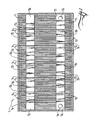
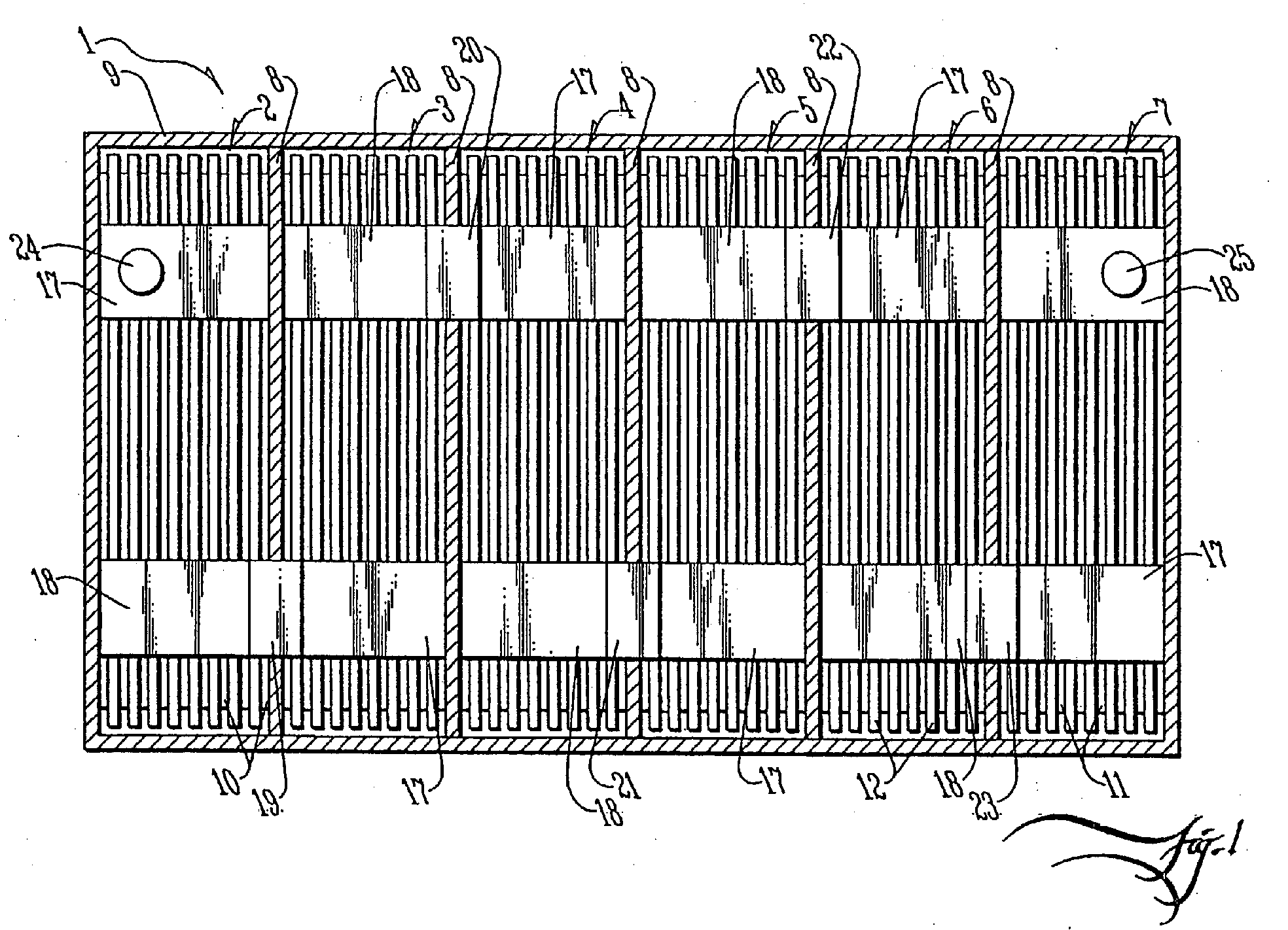
- FIGURE 1 is a top plan view of a valve-regulated lead acid (VRLA) battery 1 in accordance with the invention, which in general comprises a flat-plate arrangement.
- the battery 1 has six cells 2 to 7. Each cell is separated from a neighboring cell by means of cell partitions 8. The cells are encased in a battery casing 9.
- Each cell comprises negative plates 10 separated from positive plates 11 by means of separators 12. As shown in FIGURE 3, each negative plate has tabs 13 and 14 protruding from opposite sides. Similarly, each positive plate has tabs 15 and 16 protruding from opposite sides.
- each of the tabs 16 attached to the positive plates are connected to positive busbars 17 and each of the tabs 14 attached to the negative plates are connected to negative busbars 18.
- the negative busbar 18 of cell 2 is connected to positive busbar 17 of cell 3 by means of inter-cell welded joint 19.
- the negative busbar 18 of cell 3 is connected to the positive busbar 17 of cell 4 by welded joint 20.
- cells 4, 5, 6 and 7 are connected to each other by weld joints 21, 22 and 23, thereby connecting each of the cells in series to form a battery having a nominal capacity of 12 volts.
- FIGURE 3 shows better the inter-cell welding such as arranged vis-a-vis over the cell wall partitions.
- FIGURE 4 is a comparable view to FIGURE 3 except showing an alternate arrangement of inter-cell welding, which in this view is arranged not over but through the cell wall partitions.
- a terminal 24 is connected to the positive busbar 17 of cell 2 and a terminal 25 is connected to the negative busbar 18 of cell 7.
- the battery When viewed from the bottom as in FIGURE 2, the battery has a similar structure with positive busbars 26 connected to positive tabs 15 that are attached to the positive plates and negative busbars 27 connected to tabs 13 that are attached to the negative plates.
- cells 2, 3, 4, 5, 6 and 7 are connected by welded joints 28, 29, 30, 31 and 32 on alternate sides of the battery.
- FIGURE 2 also shows that busbar 26 of cell 2 has positive terminal 34 connected to it and negative busbar 27 of cell 7 has negative terminal 33 connected to it. Therefore, referring to both FIGURES 1 and 2, the battery 1 has two positive terminals and two negative terminals, which is also shown by either FIGURES 3 or 4 in a single view.
- FIGURE 5a is a top plan view of another embodiment of a VRLA battery 40 in accordance with the invention, comprising an arrangement of spirally-wound plates.
- the battery 40 comprises a negative plate 41, a positive plate 421 and a separator 43.
- the positive plate 42 has four positive plate tabs 44 at the top and four positive plate tabs at the bottom.
- negative plate 41 has four negative plate tabs 46 at the top and four negative plate tabs 47 at the bottom.
- the positive plate tabs 44 are connected to positive busbar 48 at the top of the battery and positive plate tabs 45 are connected to positive busbar 49 at the bottom of the battery.
- negative plate tabs 46 are connected to negative busbar 50 at the top of the battery and the negative plate tabs 47 are connected to negative busbar 51 at the bottom of the battery.
- Positive busbar 48 is connected to positive terminal 52
- negative busbar 50 is connected to negative terminal 53
- positive busbar 49 is connected to positive terminal 54
- negative busbar is connected to negative terminal 55.
- tabs 44 and 45 at the top and bottom respectively of positive plate 42 are spaced at distances that decrease as the interior of the spirally bound battery is approached so that tabs 44 and 45 coincide with busbars 48 and 49 respectively.
- the exterior of the spirally wound plate will not drain as well as the interior. This problem could be overcome by providing additional busbars and corresponding tabs at the outer ends of the spirally wound plates.
- FIGURES 6 through 9 provide graphical evaluation of how the flat-plate dual-tab battery 1 in accordance with the invention compares to a representative single-tab battery of the prior art under various conditions representative of HEV duty in some instances and EV duty in another.
- HEV battery packs are required to operate for many cycles below a full SoC. They are also subjected to high charge and discharge currents.
- the operation of commercially available, VRLA batteries under such duty has been shown to result in localized irreversible formation of lead sulphate in battery plates.
- test cycle would involve the following steps:
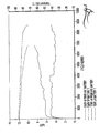
- FIGURE 6 it is a graph showing both end of discharge voltage (EoDV) and temperature (T) profiles, as graphed against number of test cycles, to afford comparison between the representative single-tab battery of the prior art and the flat-plate dual-tab battery 1 in accordance with the invention, under conditions representative of an HEV cycle rate of 2C (ie., charge and discharge occurring at a specified rate, which here corresponds to about 211 ⁇ 2 A).
- EoDV end of discharge voltage
- T temperature
- the temperature of the prior art battery measured externally at the side of the battery case, increased gradually during operation and reached 65° C at the completion of 6900 HEV cycles (FIG. 6).
- Previous studies have shown that the internal temperatures of batteries can be up to 20° C higher than external temperatures under such duty. Hence, it is considered likely that continued operation of the prior art battery could have resulted in thermal runaway, a condition that can have severe safety implications.
- the temperature of the battery 1 in accordance with the invention remained at 38 ⁇ 2° C through out its cycling period (FIG. 6). This is almost 30° C cooler than that of the prior art battery.
- the battery 1 in accordance with the invention is much less susceptible to temperature increases (and therefor, thermal runaway) under extended HEV operation than the prior art battery. This performance characteristic is very attractive to HEV manufacturers as the cooling requirements are much simplified.
- the lower operating temperature should reduce both corrosion of the positive grid and degradation of the expander used in the negative plate. Moreover, it will minimize the internal resistance of the battery 1 in accordance with the invention.
- the operating temperature of the battery 1 in accordance with the invention under HEV duty is much reduced relative to that of representative prior art batteries having just single current takeoffs.
- the inventive battery 1 provides a considerably longer cycling period between equalization charges than the prior art battery, a factor that is also very attractive to HEV manufactures.
- FIGURE 7 is a graph comparable to FIGURE 6 in that it likewise shows end of discharge voltage (EoDV) and temperature (T) profiles, as graphed against number of test cycles, for comparison of the given single-tab battery of the prior art to the flat-plate dual-tab battery in accordance with the invention, except under conditions representative of an HEV cycle rate of 4C.
- EoDV end of discharge voltage
- T temperature
- test battery 1 in accordance with the invention and the prior art battery were evaluated under an HEV duty (see above) with a charge and discharge rate of 4C.
- the increase in charge and discharge rate from 2C to 4C was expected to cause a considerable increase in the operating temperature of the batteries.
- a temperature probe was inserted in both batteries in the middle of the third cell (from the positive terminal) between the most central negative plate and adjacent separator. The temperature was also monitored externally at the hottest area on the case.
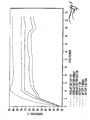
- FIGURE 8 is a graph showing only end of discharge voltage (EoDV) profiles, as graphed against number of test cycles, to afford comparison between the given single-tab battery of the prior art and the flat-plate dual-tab battery in accordance with the invention, except here under conditions representative of partial state-of-charge (PSoC)/fast-charge EV duty.
- EoDV end of discharge voltage
- the battery is discharged from 100% SoC at a given C rate of 211 ⁇ 2 A to a nominal 20% SoC (based on Ahs).
- the battery is charge at 6C (129 A) from a nominal 20% SoC until it reaches a nominal 80% SoC (based on Ahs).
- the battery is then discharged at the C rate (211 ⁇ 2 A) to a nominal 20% SoC (based on Ahs).
- the charge-discharge operation between 20 and 80% SoC without full recharging is referred to as a "PSoC cycle.”
- the PSoC process is continued for 24 PSOC cycles, or until the battery voltage at the end of discharge decreases to 11.1V, at that point the battery is deemed to be at 10% SoC, eg., an initial PSoC operating window of 20 - 80% has become 10-70% SoC. (Note:- one set of 24 PSoC cycles is referred to as a "master cycle").
- the results of the cycling are shown in FIGURE 8.
- the EoDV of the prior art battery initially increases in response to a rise in battery temperature, caused by the commencement of fast charging. The EoDV then decreases steadily from 11.75 to 11.45 V during the remainder of the master cycle, presumably as a result of charging inefficiencies.
- the EoDV recovered after equalization charging (Regime 3), but then decreased gradually to 11.45 V during the second master cycle.
- the EoDV after the 1st discharge of the third master cycle had decreased to 11.15 V, compared to 11.45 V during the first and second master cycles. This "irreversible" degradation of the EoDV continued, with the battery voltage reaching the cut-off limit of 11.10 V during the last discharge of the fourth master cycle. In all subsequent master cycles, the battery was unable to deliver 24 cycles before reaching the cut-off voltage.
- the EoDV of the battery 1 in accordance with the invention remained at a much higher level throughout PSoC/fast-charge operation, compared to that of the representative battery of the prior art (FIG. 8).
- the EoDV of the inventive battery 1 during the last discharge of the first and final master cycles were 11.70 and 11.50 V, respectively, compared 11.45 and 11.10 V for the prior art battery.
- the battery 1 in accordance with the invention is more resistant to capacity loss under PSoC/fast-charge duty and, as a consequence, was able to deliver the required number of PSoC cycles throughout all the testing period.
- thermocouples were installed in the third cell and were positioned between the middle negative plate and adjacent separator in the following positions:
- FIGURE 9 shows the internal temperature of both batteries at the completion of charging during a typical master cycle.
- a temperature gradient formed quickly in the prior art battery during initial operation. After four cycles, the internal battery temperature reached 90, 75 and 70° C at the top, middle and bottom, respectively. The extent of the rise was surprising, given that the external temperature, measured at the hottest point on the outside of the battery case, was limited to 55° C.
- the internal temperature of the dual-tab battery 1 in accordance with the invention increased gradually during initial PSoC/fast-charge operation, reaching approximately 65° after 15 cycles. During this time, the temperature differential from the top to the bottom of the battery did not exceed 5° C. Hence, the battery 1 in accordance with the invention has both a lower average battery temperature and a reduced internal temperature differential, compared to the single-tab battery of the prior art, when operated under PSoC/fast-charge conditions.
- the hotter battery will experience the highest active-material utilization during discharge.
- the hot battery will also accept the greatest amount of charge for a given charge time and top-of-charge voltage. Given that the top and bottom regions of a battery plate are effectively in parallel, it follows then that if they were at different temperatures, they would experience different degrees of active-material utilization during discharge. Also, the hotter locations would experience a higher degree of overcharge relative to the cooler areas.
- the dual-tab design in accordance with the invention does not develop significant temperature gradients during either HEV or PSoC/fast-charge EV duty. Presumably it is for that reason that the inventive dual-tab battery does not suffer from preferential sulphation.
- the invention relates to a valve-regulated lead acid battery cell of flat plural-tab plates, comprising:
- the invention further refers to a plural-cell valve-regulated lead acid battery having cells of flat plural-tab plates, comprising:
- valve-regulated lead acid battery cell of spiral plural-tab plates comprising:
Landscapes
- Chemical & Material Sciences (AREA)
- Chemical Kinetics & Catalysis (AREA)
- Electrochemistry (AREA)
- General Chemical & Material Sciences (AREA)
- Secondary Cells (AREA)
Abstract
Description
wherein the cell compartments preferably have at least a common headroom
wherein the fused busbars are preferably through the partition walls and
wherein the fused busbars preferably lap the partition walls as well as an electric or hybrid electric vehicle comprising one or more batteries as described above.
Claims (8)
- A plural-cell valve-regulated lead acid battery having cells of flat plural-tab plates, comprising:plural layered, cell assemblies, each having a plurality of charged and oppositely-charged plates and another plurality of separator media interleaved between the plates;each plate having a peripheral edge formed with at least one and another tab groups wherein each layered cell assembly is arranged such that the at least one and another tab groups of the charged plates and the at least on and another tab groups of the oppositely-charged plates present a first, second, third and fourth row respectively of tab groups;each layered cell assembly further comprising at least a first, second, third and fourth busbar electrically coupled to the first, second, third and fourth rows of tab groups respectively;a sealed case encasing said cell assemblies and comprising at least one partition wall to subdivide the case into at least plural cell compartments, each cell compartment being sized for containing one layered cell assembly;said partition wall defining a plane such that on one side of the partition wall a given layered cell assembly has at least one of the first and third busbars and at least one of the second and fourth busbars formed with proximal ends extended to the plane as on the other side of the partition wall another layered cell assembly correspondingly has at least one of the first and third busbars and at least one of the second and fourth busbars formed with proximal ends extended to the plane, wherein the respectively extended busbars are fused to provide an electrical path therebetween; and,at least a first, second, third and fourth terminal connected for electrically servicing the at least a first, second, third and fourth busbars respectively whereby said battery is serviced by at least plural pairs of charged and oppositely-charged terminals.
- The battery of claim 1 wherein the cell compartments are independently sealed airtight.
- The battery of claim 1 or 2 wherein the cell compartments have at least a common headroom.
- The battery of any of the claims 1 to 3 wherein the fused busbars are through the partition walls.
- The battery of any of the claims 1 to 4 wherein the fused busbars lap the partition walls.
- An electric or hybrid electric vehicle comprising one or more batteries according to any of the claims 1 to 5.
- A valve-regulated lead acid battery cell of flat plural-tab plates, comprising:a layered assembly having a plurality of negative and positive plates and another plurality of separator media interleaved between the plates;each plate having a peripheral edge formed with at least one and another tab groups substantially spread apart on the peripheral edge so that each tab group services the current flux in or out of a geometric proportion of the plate about proportional to the number of tab groups for the plate, wherein the layered assembly is arranged such that the at least one and another tab groups of the negative plates and the at least one and another tab groups of the positive plates present a first, second, third and fourth row respectively of tab groups;at least a first, second, third and fourth busbar wherein each busbar has a slotted face formed with tab slots for receiving tabs of plates and further wherein the first, second, third and fourth busbars are electrically coupled to the first, second, third and fourth rows of tab groups respectively by the tabs being received in the tab slots, which thereby affords relatively compact busbars to service the rows of tab groups and thus economizes weight attributable to the busbars; and,at least a first, second, third and fourth terminal connected for electrically servicing the at least a first, second, third and fourth busbars respectively whereby said battery cell is serviced by at least plural pairs of positive and negative terminals.
- An electric or hybrid electric vehicle comprising one or more cells according to claim 7.
Applications Claiming Priority (5)
| Application Number | Priority Date | Filing Date | Title |
|---|---|---|---|
| US19507900P | 2000-04-06 | 2000-04-06 | |
| US195079P | 2000-04-06 | ||
| US09/707,753 US6555265B1 (en) | 2000-04-06 | 2000-11-06 | Value regulated lead acid battery |
| US707753 | 2000-11-06 | ||
| EP00993863A EP1287567B1 (en) | 2000-04-06 | 2000-11-07 | Valve regulated lead acid battery |
Related Parent Applications (1)
| Application Number | Title | Priority Date | Filing Date |
|---|---|---|---|
| EP00993863A Division EP1287567B1 (en) | 2000-04-06 | 2000-11-07 | Valve regulated lead acid battery |
Publications (3)
| Publication Number | Publication Date |
|---|---|
| EP1610402A2 true EP1610402A2 (en) | 2005-12-28 |
| EP1610402A3 EP1610402A3 (en) | 2006-03-01 |
| EP1610402B1 EP1610402B1 (en) | 2009-05-06 |
Family
ID=35427208
Family Applications (1)
| Application Number | Title | Priority Date | Filing Date |
|---|---|---|---|
| EP05017330A Expired - Lifetime EP1610402B1 (en) | 2000-04-06 | 2000-11-07 | Valve regulated lead acid battery |
Country Status (1)
| Country | Link |
|---|---|
| EP (1) | EP1610402B1 (en) |
Cited By (2)
| Publication number | Priority date | Publication date | Assignee | Title |
|---|---|---|---|---|
| WO2013059115A1 (en) * | 2011-10-21 | 2013-04-25 | Tyco Electronics Corporation | Battery connector system |
| CN110690309A (en) * | 2019-09-30 | 2020-01-14 | 无锡奥特维智能装备有限公司 | Bus bar installation equipment, tab processing system and bus bar installation method |
Family Cites Families (4)
| Publication number | Priority date | Publication date | Assignee | Title |
|---|---|---|---|---|
| US3518127A (en) * | 1967-12-26 | 1970-06-30 | Electric Fuel Propulsion Inc | Floor interconnecting battery cells |
| US4603093A (en) * | 1983-02-03 | 1986-07-29 | California Institute Of Technology | Lead-acid battery |
| DE3610951A1 (en) * | 1986-04-02 | 1987-10-08 | Hagen Batterie Ag | NEGATIVE ELECTRODE FOR LEAD ACCUMULATORS |
| US4983475A (en) * | 1990-02-13 | 1991-01-08 | Delans Darwin D | Bar for connecting together two plate straps of the same polarity on an electrochemical battery |
-
2000
- 2000-11-07 EP EP05017330A patent/EP1610402B1/en not_active Expired - Lifetime
Cited By (3)
| Publication number | Priority date | Publication date | Assignee | Title |
|---|---|---|---|---|
| WO2013059115A1 (en) * | 2011-10-21 | 2013-04-25 | Tyco Electronics Corporation | Battery connector system |
| US9005794B2 (en) | 2011-10-21 | 2015-04-14 | Tyco Electronics Corporation | Battery connector system |
| CN110690309A (en) * | 2019-09-30 | 2020-01-14 | 无锡奥特维智能装备有限公司 | Bus bar installation equipment, tab processing system and bus bar installation method |
Also Published As
| Publication number | Publication date |
|---|---|
| EP1610402B1 (en) | 2009-05-06 |
| EP1610402A3 (en) | 2006-03-01 |
Similar Documents
| Publication | Publication Date | Title |
|---|---|---|
| EP1287567B1 (en) | Valve regulated lead acid battery | |
| AU2001229219A1 (en) | Valve regulated lead acid battery | |
| KR100784184B1 (en) | Battery assembly | |
| US6953638B2 (en) | Fluid-cooled battery pack system | |
| KR101240961B1 (en) | Battery Pack Having Novel Structure | |
| US20070111089A1 (en) | Electrochemical cell for hybrid electric vehicle applications | |
| Lam et al. | Advanced design of valve-regulated lead–acid battery for hybrid electric vehicles | |
| US20130309554A1 (en) | Lead-acid battery with high specific power and specific energy | |
| EP1610402B1 (en) | Valve regulated lead acid battery | |
| CN100350648C (en) | Valve regulated lead acid battery | |
| Bhardwaj et al. | Lead acid battery with thin metal film (TMF®) technology for high power applications | |
| Kohler | Hybrid electric vehicles: Batteries | |
| JP7699623B2 (en) | Electricity storage module and manufacturing method thereof | |
| JP7696389B2 (en) | Electricity storage module and manufacturing method thereof | |
| JP7271488B2 (en) | Method for manufacturing nickel-metal hydride storage battery | |
| JP7713989B2 (en) | Electricity storage module and manufacturing method thereof | |
| JP7696390B2 (en) | Electricity storage module and manufacturing method thereof | |
| US20250192369A1 (en) | Electrode assembly, battery cell, battery and electrical device | |
| HK1056950B (en) | Valve regulated lead acid battery | |
| US20130309550A1 (en) | Lead-acid battery with high power density and energy density | |
| HK1091949B (en) | Valve regulated lead acid battery | |
| CN113594424A (en) | Method for manufacturing nickel-metal hydride storage battery | |
| JP2002008736A (en) | Monoblock batteries and assembled batteries |
Legal Events
| Date | Code | Title | Description |
|---|---|---|---|
| PUAI | Public reference made under article 153(3) epc to a published international application that has entered the european phase |
Free format text: ORIGINAL CODE: 0009012 |
|
| AC | Divisional application: reference to earlier application |
Ref document number: 1287567 Country of ref document: EP Kind code of ref document: P |
|
| AK | Designated contracting states |
Kind code of ref document: A2 Designated state(s): AT BE CH CY DE DK ES FI FR GB GR IE IT LI LU MC NL PT SE TR |
|
| PUAL | Search report despatched |
Free format text: ORIGINAL CODE: 0009013 |
|
| RIC1 | Information provided on ipc code assigned before grant |
Ipc: H01M 2/26 20060101AFI20051220BHEP Ipc: H01M 2/30 20060101ALI20051220BHEP Ipc: H01M 2/24 20060101ALI20051220BHEP Ipc: H01M 2/28 20060101ALI20051220BHEP |
|
| AK | Designated contracting states |
Kind code of ref document: A3 Designated state(s): AT BE CH CY DE DK ES FI FR GB GR IE IT LI LU MC NL PT SE TR |
|
| RIN1 | Information on inventor provided before grant (corrected) |
Inventor name: FLEMING, FRANK, ALBERT Inventor name: NEWNHAM, RUSSEL, HARVEY |
|
| 17P | Request for examination filed |
Effective date: 20060817 |
|
| 17Q | First examination report despatched |
Effective date: 20060925 |
|
| AKX | Designation fees paid |
Designated state(s): AT BE CH CY DE DK ES FI FR GB GR IE IT LI LU MC NL PT SE TR |
|
| GRAP | Despatch of communication of intention to grant a patent |
Free format text: ORIGINAL CODE: EPIDOSNIGR1 |
|
| GRAS | Grant fee paid |
Free format text: ORIGINAL CODE: EPIDOSNIGR3 |
|
| GRAA | (expected) grant |
Free format text: ORIGINAL CODE: 0009210 |
|
| AC | Divisional application: reference to earlier application |
Ref document number: 1287567 Country of ref document: EP Kind code of ref document: P |
|
| AK | Designated contracting states |
Kind code of ref document: B1 Designated state(s): AT BE CH CY DE DK ES FI FR GB GR IE IT LI LU MC NL PT SE TR |
|
| REG | Reference to a national code |
Ref country code: GB Ref legal event code: FG4D |
|
| REG | Reference to a national code |
Ref country code: CH Ref legal event code: EP |
|
| REG | Reference to a national code |
Ref country code: IE Ref legal event code: FG4D |
|
| REF | Corresponds to: |
Ref document number: 60042176 Country of ref document: DE Date of ref document: 20090618 Kind code of ref document: P |
|
| REG | Reference to a national code |
Ref country code: ES Ref legal event code: FG2A Ref document number: 2325926 Country of ref document: ES Kind code of ref document: T3 |
|
| PG25 | Lapsed in a contracting state [announced via postgrant information from national office to epo] |
Ref country code: PT Free format text: LAPSE BECAUSE OF FAILURE TO SUBMIT A TRANSLATION OF THE DESCRIPTION OR TO PAY THE FEE WITHIN THE PRESCRIBED TIME-LIMIT Effective date: 20090906 Ref country code: FI Free format text: LAPSE BECAUSE OF FAILURE TO SUBMIT A TRANSLATION OF THE DESCRIPTION OR TO PAY THE FEE WITHIN THE PRESCRIBED TIME-LIMIT Effective date: 20090506 Ref country code: AT Free format text: LAPSE BECAUSE OF FAILURE TO SUBMIT A TRANSLATION OF THE DESCRIPTION OR TO PAY THE FEE WITHIN THE PRESCRIBED TIME-LIMIT Effective date: 20090506 |
|
| NLV1 | Nl: lapsed or annulled due to failure to fulfill the requirements of art. 29p and 29m of the patents act | ||
| PG25 | Lapsed in a contracting state [announced via postgrant information from national office to epo] |
Ref country code: SE Free format text: LAPSE BECAUSE OF FAILURE TO SUBMIT A TRANSLATION OF THE DESCRIPTION OR TO PAY THE FEE WITHIN THE PRESCRIBED TIME-LIMIT Effective date: 20090806 Ref country code: NL Free format text: LAPSE BECAUSE OF FAILURE TO SUBMIT A TRANSLATION OF THE DESCRIPTION OR TO PAY THE FEE WITHIN THE PRESCRIBED TIME-LIMIT Effective date: 20090506 |
|
| PG25 | Lapsed in a contracting state [announced via postgrant information from national office to epo] |
Ref country code: DK Free format text: LAPSE BECAUSE OF FAILURE TO SUBMIT A TRANSLATION OF THE DESCRIPTION OR TO PAY THE FEE WITHIN THE PRESCRIBED TIME-LIMIT Effective date: 20090506 |
|
| PG25 | Lapsed in a contracting state [announced via postgrant information from national office to epo] |
Ref country code: BE Free format text: LAPSE BECAUSE OF FAILURE TO SUBMIT A TRANSLATION OF THE DESCRIPTION OR TO PAY THE FEE WITHIN THE PRESCRIBED TIME-LIMIT Effective date: 20090506 |
|
| PLBE | No opposition filed within time limit |
Free format text: ORIGINAL CODE: 0009261 |
|
| STAA | Information on the status of an ep patent application or granted ep patent |
Free format text: STATUS: NO OPPOSITION FILED WITHIN TIME LIMIT |
|
| 26N | No opposition filed |
Effective date: 20100209 |
|
| PG25 | Lapsed in a contracting state [announced via postgrant information from national office to epo] |
Ref country code: GR Free format text: LAPSE BECAUSE OF FAILURE TO SUBMIT A TRANSLATION OF THE DESCRIPTION OR TO PAY THE FEE WITHIN THE PRESCRIBED TIME-LIMIT Effective date: 20090807 |
|
| PG25 | Lapsed in a contracting state [announced via postgrant information from national office to epo] |
Ref country code: TR Free format text: LAPSE BECAUSE OF FAILURE TO SUBMIT A TRANSLATION OF THE DESCRIPTION OR TO PAY THE FEE WITHIN THE PRESCRIBED TIME-LIMIT Effective date: 20090506 |
|
| PG25 | Lapsed in a contracting state [announced via postgrant information from national office to epo] |
Ref country code: CY Free format text: LAPSE BECAUSE OF FAILURE TO SUBMIT A TRANSLATION OF THE DESCRIPTION OR TO PAY THE FEE WITHIN THE PRESCRIBED TIME-LIMIT Effective date: 20090506 |
|
| PGFP | Annual fee paid to national office [announced via postgrant information from national office to epo] |
Ref country code: MC Payment date: 20140926 Year of fee payment: 15 |
|
| PGFP | Annual fee paid to national office [announced via postgrant information from national office to epo] |
Ref country code: LU Payment date: 20141119 Year of fee payment: 15 |
|
| PGFP | Annual fee paid to national office [announced via postgrant information from national office to epo] |
Ref country code: FR Payment date: 20141110 Year of fee payment: 15 Ref country code: CH Payment date: 20141112 Year of fee payment: 15 Ref country code: IE Payment date: 20141110 Year of fee payment: 15 Ref country code: GB Payment date: 20141105 Year of fee payment: 15 Ref country code: DE Payment date: 20141105 Year of fee payment: 15 Ref country code: ES Payment date: 20141013 Year of fee payment: 15 |
|
| PGFP | Annual fee paid to national office [announced via postgrant information from national office to epo] |
Ref country code: IT Payment date: 20141114 Year of fee payment: 15 |
|
| REG | Reference to a national code |
Ref country code: DE Ref legal event code: R119 Ref document number: 60042176 Country of ref document: DE |
|
| PG25 | Lapsed in a contracting state [announced via postgrant information from national office to epo] |
Ref country code: LU Free format text: LAPSE BECAUSE OF NON-PAYMENT OF DUE FEES Effective date: 20151107 Ref country code: MC Free format text: LAPSE BECAUSE OF NON-PAYMENT OF DUE FEES Effective date: 20151130 |
|
| REG | Reference to a national code |
Ref country code: CH Ref legal event code: PL |
|
| GBPC | Gb: european patent ceased through non-payment of renewal fee |
Effective date: 20151107 |
|
| PG25 | Lapsed in a contracting state [announced via postgrant information from national office to epo] |
Ref country code: IT Free format text: LAPSE BECAUSE OF NON-PAYMENT OF DUE FEES Effective date: 20151107 Ref country code: LI Free format text: LAPSE BECAUSE OF NON-PAYMENT OF DUE FEES Effective date: 20151130 Ref country code: CH Free format text: LAPSE BECAUSE OF NON-PAYMENT OF DUE FEES Effective date: 20151130 |
|
| REG | Reference to a national code |
Ref country code: IE Ref legal event code: MM4A |
|
| REG | Reference to a national code |
Ref country code: FR Ref legal event code: ST Effective date: 20160729 |
|
| PG25 | Lapsed in a contracting state [announced via postgrant information from national office to epo] |
Ref country code: DE Free format text: LAPSE BECAUSE OF NON-PAYMENT OF DUE FEES Effective date: 20160601 Ref country code: IE Free format text: LAPSE BECAUSE OF NON-PAYMENT OF DUE FEES Effective date: 20151107 Ref country code: GB Free format text: LAPSE BECAUSE OF NON-PAYMENT OF DUE FEES Effective date: 20151107 |
|
| PG25 | Lapsed in a contracting state [announced via postgrant information from national office to epo] |
Ref country code: FR Free format text: LAPSE BECAUSE OF NON-PAYMENT OF DUE FEES Effective date: 20151130 |
|
| REG | Reference to a national code |
Ref country code: ES Ref legal event code: FD2A Effective date: 20161227 |
|
| PG25 | Lapsed in a contracting state [announced via postgrant information from national office to epo] |
Ref country code: ES Free format text: LAPSE BECAUSE OF NON-PAYMENT OF DUE FEES Effective date: 20151108 |