EP1610163A1 - Cable element having repositionable pressure sensitive adhesive to couple buffer tubes to a central strength member - Google Patents
Cable element having repositionable pressure sensitive adhesive to couple buffer tubes to a central strength member Download PDFInfo
- Publication number
- EP1610163A1 EP1610163A1 EP05076456A EP05076456A EP1610163A1 EP 1610163 A1 EP1610163 A1 EP 1610163A1 EP 05076456 A EP05076456 A EP 05076456A EP 05076456 A EP05076456 A EP 05076456A EP 1610163 A1 EP1610163 A1 EP 1610163A1
- Authority
- EP
- European Patent Office
- Prior art keywords
- strength member
- central strength
- sensitive adhesive
- pressure sensitive
- buffer tubes
- Prior art date
- Legal status (The legal status is an assumption and is not a legal conclusion. Google has not performed a legal analysis and makes no representation as to the accuracy of the status listed.)
- Granted
Links
Images

Classifications
-
- G—PHYSICS
- G02—OPTICS
- G02B—OPTICAL ELEMENTS, SYSTEMS OR APPARATUS
- G02B6/00—Light guides; Structural details of arrangements comprising light guides and other optical elements, e.g. couplings
- G02B6/44—Mechanical structures for providing tensile strength and external protection for fibres, e.g. optical transmission cables
- G02B6/4401—Optical cables
- G02B6/4429—Means specially adapted for strengthening or protecting the cables
- G02B6/4434—Central member to take up tensile loads
-
- G—PHYSICS
- G02—OPTICS
- G02B—OPTICAL ELEMENTS, SYSTEMS OR APPARATUS
- G02B6/00—Light guides; Structural details of arrangements comprising light guides and other optical elements, e.g. couplings
- G02B6/44—Mechanical structures for providing tensile strength and external protection for fibres, e.g. optical transmission cables
- G02B6/4401—Optical cables
- G02B6/441—Optical cables built up from sub-bundles
Definitions
- the present invention relates to an cable element having buffer tubes that easily are removable and re-applicable to a central strength member (CSM).
- CSM central strength member
- the present invention relates to an optical cable element using a repositionable pressure sensitive adhesive to couple buffer tubes to a central strength member, such as a glass reinforced plastic (GRP).
- GRP glass reinforced plastic
- buffer tubes are stranded (for example, helically or reverse helically) around a central strength member to form a stranded core.
- the thin walled buffer tubes are bound to the central strength member using a binder, yarn, or thread.
- each of the buffer tubes house an optical unit, such as one or more optical fibers or an optical fiber ribbon having a plurality of optical fibers that are held together in a planar array.
- the related art optical cable elements have several disadvantages.
- the fibers inside the smaller buffer tubes which may be less than 2 mm in diameter and have a wall thickness from 0.05 to 1 mm, can become stressed from mechanical forces from the interior of the cable. This is because polymeric buffer tube walls are compliant at such a thin wall thickness.
- the cable elements of related art have the adverse effect of exposing the optical fibers to radial stresses that are applied during further manufacturing steps. These stresses can originate from components such as the binders, the water swellable material, or the interior of the jacket,
- the optical cable elements are formed by binding a thin walled buffer tube to a central strength member using a binder, yarn, or thread.
- a binder yarn, or thread.
- the buffer tubes of the related art can be difficult to access in the field.
- the binders or other similar stranding materials induce undesirable stresses on the buffer tubes.
- the present invention is directed to a cable element that addresses the problems discussed above, as well as others. Specifically, the present invention relates to a cable element that reduces the amount of packaging, eliminates stranding materials and the stranding step, and improves access, particularly, access in the field. Additionally, the present invention eliminates binder materials and water swellable materials, and correspondingly, eliminates the stresses that would be induced on the buffer tubes by such binder materials or water swellable materials.
- the present invention provides buffer tubes that are bonded adhesively to a central strength member, thereby eliminating the stranding material and the stranding step, as well as the stresses resulting therefrom. More particularly, the present invention couples the buffer tubes to the central strength member using a pressure sensitive adhesive that is a repositionable adhesive. In the present invention, the individual buffer tubes can be removed and reapplied to the central strength member, thereby permitting the buffer tubes to be kept in a more ordered cylindrical structure.
- the cable element of the present invention comprises a central strength member, a plurality of buffer tubes disposed on the central strength member, and a layer of releasable pressure sensitive adhesive provided on the central strength member, wherein the layer of pressure sensitive adhesive releasably adheres the buffer tubes to the central strength member.
- the buffer tubes include at least one signal transmission element.
- Figure 1 is a cross-section showing the buffer tubes bonded to the central strength member, such as a GRP.
- the buffer tubes are bonded across the length and have the applied twist from the oscillator.
- Figure 2 is a side view according to an illustrative, non-limiting embodiment of the present invention.
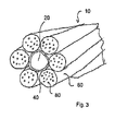
- Figure 3 is a perspective view according to yet another illustrative, non-limiting embodiment of the present invention.
- the cable element 10 includes a central strength member 20, a plurality of buffer tubes 60 disposed on the central strength member 20, and a layer of repositionable pressure sensitive adhesive 40.
- the buffer tubes 60 each enclose at least one optical fiber 80.
- the plurality of buffer tubes 60 can be wrapped around the central strength member 20 in any configuration, such as an SZ configuration.
- the layer of repositionable pressure sensitive adhesive 40 couples the plurality of buffer tubes 60 to the central strength member 20.
- the layer of repositionable pressure sensitive adhesive 40 is permanently elastic.
- the layer of pressure sensitive adhesive 40 also may be a hot melt adhesive at ambient temperature.
- the layer of repositionable pressure sensitive adhesive 40 releasably couples the plurality of buffer tubes 60 to the central strength member 20.
- the fact that the pressure sensitive adhesive 40 is a repositionable adhesive allows the buffer tubes 60 to be removed from the central strength member 20 and to be applied again to central strength member 20 without the adhesive 40 losing its effectiveness.
- the layer of repositionable pressure sensitive adhesive 40 allows at least one of the buffer tubes 60 to be manually uncoupled from the central strength member 20 solely by exerting a force on the buffer tube 60 in a direction away from the central strength member 20.
- the direction away from the central strength member 20 can be any direction that causes one of the buffer tubes 60 to pull away from the central strength member 20.
- the buffer tube 60 also can be re-coupled to the central strength member 20 solely by exerting a force on the buffer tube 60 in a direction toward the central strength member 20. That is, by pushing the buffer tube 60 against the central strength member 20, the buffer tube 60 can be manually recoupled to the central strength member 20 by the repositionable pressure sensitive adhesive 40. In this way, the buffer tubes 60 of the present invention repeatedly can be coupled to and uncoupled from the central strength member, thereby providing, among other things, improved access in the field.
- the coupling and recoupling of the buffer tubes to the central strength member can be accomplished at ambient temperature without subjecting the layer of repositionable pressure sensitive adhesive 40 to a heat source. In other words, no heating of the repositionable pressure sensitive adhesive 40 is necessary to uncouple or couple the buffer tubes 60 from the central strength member 20.
- the buffer tubes 60 can be uncoupled from, and re-coupled to, the central strength member at ambient temperature without subjecting the layer of pressure sensitive adhesive 40 to a chemical reaction with any additional materials.
- the repositionable pressure sensitive adhesive 40 is operable to couple and uncouple the buffer tubes 60 to and from the central strength member 20 over the entire use range of the optical cable element 10. In this way, the layer of repositionable pressure sensitive adhesive 40 permits the plurality of buffer tubes 60 to be releasably adhered to the central strength member 20.
- the layer of repositionable pressure sensitive adhesive 40 is provided as a thin layer around the central strength member 20. That is, the layer of pressure sensitive adhesive 40 does not flow around the individual buffer tubes 60. Therefore, the adhesive 40 does not leave a resin residue on the buffer tubes 60 when the buffer tubes 60 are uncoupled from the central strength member 20. Because there is no residue to be removed from the uncoupled buffer tubes 40 with a shaving tool, the process of cleaning the buffer tubes 40 is simplified.
- the optical cable element of the present invention is made by applying a layer of repositionable pressure sensitive adhesive 40 on a surface of a central strength member 20, then releasably coupling a plurality of buffer tubes 60 on the central strength member 20 by laying the buffer tubes 60 on the repositionable pressure sensitive adhesive 40.
- the repositionable pressure sensitive adhesive 40 is preferably provided along the entire length of the central strength member 20 so that the buffer tubes 60 are bonded to the central strength member along their entire length.
- the invention is not limited in this respect, and the adhesive 40 can be applied intermittently to the central strength member 20.
- the appropriate twist is applied to the buffer tubes by an oscillator.
- the buffer tubes can be coupled to the central strength member by applying pressure to the plurality of buffer tubes in a direction toward the central strength member or in a manner that initiates contact between the buffer tubes and the pressure sensitive adhesive. Therefore, no binders are necessary to couple the buffer tubes to the central strength member.
- the plurality of buffer tubes can be wrapped around the central strength member in an SZ configuration, among other configurations.
- the layer of pressure sensitive adhesive may be permanently elastic. Additionally, the layer of pressure sensitive adhesive may be a hot melt adhesive at ambient temperature.
- the optical cable element is formed by the further steps of: uncoupling at least one buffer tube of the plurality of buffer tubes from the central strength member; and re-coupling the at least one buffer tube to the central strength member at ambient temperature without subjecting the layer of pressure sensitive adhesive to a heat source.
- the optical cable element is formed by the further steps of: uncoupling at least one buffer tube of the plurality of buffer tubes from the central strength member; and re-coupling the at least one buffer tube to the central strength member at ambient temperature without subjecting the layer of pressure sensitive adhesive to a chemical reaction from exposure to an additional material.
- initial samples were made with 1.4 mm polyolefin buffer tubes adhesively bonded to a 1.7 mm GRP pipe.
- Soft polyolefin buffer tubes were also used in the initial samples and were easy to manufacture and remained bonded from -40 °C to 70 °C.
- the adhesive was applied to the glass reinforced plastic pipe through a die. More particularly, the adhesive used was Henkel Q8735 PSA and it was applied through a 1.9 mm die. The procedure worked flawlessly with both the adhesive and buffer tubes lying down easily on top of the GRP. Further, the adhesive was applied ahead of the oscillator and there were no problems with build-up.
- the buffer tubes it is possible to implement a pressure sensitive adhesive that is flexible over the use range of the cable to couple the buffer tubes to the central strength member.
- This allows the buffer tubes to be coupled to the central strength member without binders. This is advantageous because, once the cable element is accessed through the jacket, the buffer tubes can be accessed without cutting and/or removing the binding materials.
- the binder In contrast, in the related art, the binder must be cut to access the buffer tubes.
- Another advantage of the present invention is that the adhesion to the central strength member also controls the coefficient of thermal expansion (CTE) of the buffer tubes by coupling them to the low CTE central strength member.
- CTE coefficient of thermal expansion
- the buffer tubes are manually accessible, and therefore, can be accessed easily in the field by a field technician.
- the repositionable adhesive is used to couple the thin walled buffer tubes to the central strength member, the buffer tubes lay down precisely as the oscillator moves them, so the anticipated and actual amount of turns match.
- the present invention has the added advantage of allowing individual buffer tubes to be removed and reapplied easily at the installers' discretion.
- the movement of the buffer tubes with temperature will be controlled more by the thermal expansion of the central strength member and be less random in nature.
- the need for binding can be eliminated and access to the buffer tubes can be improved. Additionally, binders and water swellable materials can be eliminated. Further, the stresses resulting from the use of binders, water swellable material, and/or the interior of the jacket can be eliminated.
- the aforementioned advantages of the present invention can be accomplished by providing an optical cable element having buffer tubes that are bonded adhesively to a central strength member using a repositionable pressure sensitive adhesive, thereby eliminating the stranding material and the stranding step, as well as the stresses resulting therefrom.
- the repositionable pressure sensitive adhesive can be a permanently elastic adhesive.
- the present invention has the advantage that productivity, quality assurance, and product novelty can be increased. Further, the present invention has the advantage that the buffer tubes can be accessed by pulling the tubes away from the central strength member without damaging the tubes. Thus, the buffer tubes of the present invention can be separated manually in the field, simply by peeling off the buffer tubes. Similarly, the buffer tubes can be reapplied to the central strength member easily by hand in the field, simply by pressing the buffer tubes back onto the central strength member. As such, the buffer tubes of the present invention easily can be removed, repositioned, or reapplied to their original position.
Landscapes
- Physics & Mathematics (AREA)
- General Physics & Mathematics (AREA)
- Optics & Photonics (AREA)
- Adhesives Or Adhesive Processes (AREA)
- Light Guides In General And Applications Therefor (AREA)
- Standing Axle, Rod, Or Tube Structures Coupled By Welding, Adhesion, Or Deposition (AREA)
Abstract
Description
Claims (22)
- A cable element comprising:wherein the layer of repositionable pressure sensitive adhesive couples the plurality of buffer tubes to the central strength member.a central strength member;a plurality of buffer tubes disposed on the central strength member, wherein each of the plurality of buffer tubes encloses at least one signal transmission element; anda layer of pressure sensitive adhesive provided on the central strength member, wherein the pressure sensitive adhesive is a repositionable adhesive;
- The cable element according to claim 1, wherein the at least one signal transmission element is an optical fiber.
- The cable element according to any one of claims 1-2, wherein the plurality of buffer tubes are wrapped around the central strength member in an SZ configuration.
- The cable element according to any one of claims 1-3, wherein the layer of pressure sensitive adhesive is permanently elastic.
- The cable element according to any one of claims 1-4, wherein the layer of pressure sensitive adhesive is a hot melt adhesive at ambient temperature.
- The cable element according to any one of claims 1-5, wherein the layer of pressure sensitive adhesive covers an entire surface of the central strength member.
- The cable element according to any one of claims 1-6, wherein each of the plurality of buffer tubes are coupled to the central strength member by the layer of pressure sensitive adhesive along an entire length of each of the plurality of buffer tubes.
- The cable element according to any one of claims 1-7, wherein the layer of pressure sensitive adhesive is a thin layer provided around the central strength member that does not flow around the individual buffer tubes.
- A cable element comprising:wherein the layer of pressure sensitive adhesive releasably couples the plurality of buffer tubes to the central strength member.a central strength member;a plurality of buffer tubes disposed on the central strength member, wherein each of the plurality of buffer tubes encloses at least one signal transmission element; anda layer of pressure sensitive adhesive;
- The cable element according to claim 9, wherein the at least one signal transmission element is an optical fiber.
- The cable element according to any one of claims 9-10, wherein the layer of pressure sensitive adhesive is adapted to allow at least one buffer tube of the plurality of buffer tubes to be uncoupled from the central strength member solely by exerting a force on the at least one buffer tube in a direction away from the central strength member, and re-coupled to the central strength member solely by exerting a force on the at least one buffer tube in a direction toward the central strength member.
- The cable element according to any one of claims 9-11, wherein the layer of pressure sensitive adhesive is adapted to allow at least one buffer tube of the plurality of buffer tubes to be uncoupled from, and re-coupled to, the central strength member at ambient temperature without subjecting the layer of pressure sensitive adhesive to a heat source.
- The cable element according to any one of claims 9-12, wherein the layer of pressure sensitive adhesive is adapted to allow at least one buffer tube of the plurality of buffer tubes to be uncoupled from, and re-coupled to, the central strength member at ambient temperature without subjecting the layer of pressure sensitive adhesive to a chemical reaction with additional material.
- The cable element according to any one of claims 9-13, wherein the layer of pressure sensitive adhesive is a thin layer provided around the central strength member that does not flow around the individual buffer tubes.
- A method of forming an optical cable element comprising:applying a layer of pressure sensitive adhesive on a surface of a central strength member, wherein the pressure sensitive adhesive is a repositionable adhesive;releasably coupling a plurality of buffer tubes on the central strength member by applying pressure to the plurality of buffer tubes in a direction toward the central strength member, wherein each of the plurality of buffer tubes encloses at least one signal transmission element.
- The method according to claim 15, wherein each of the plurality of buffer tubes encloses at least one signal transmission element.
- The method according to any one of claims 15-16, further comprising wrapping the plurality of buffer tubes around the central strength member in an SZ configuration.
- The method according to any one of claims 15-17, wherein the layer of pressure sensitive adhesive is permanently elastic.
- The method according to any one of claims 15-18, wherein the layer of pressure sensitive adhesive is a hot melt adhesive at ambient temperature.
- The method according to any one of claims 15-19, further comprising the steps of:uncoupling at least one buffer tube of the plurality of buffer tubes from the central strength member; andre-coupling the at least one buffer tube to the central strength member at ambient temperature without subjecting the layer of pressure sensitive adhesive to a heat source.
- The method according to any one of claims 15-20, further comprising the steps of:uncoupling at least one buffer tube of the plurality of buffer tubes from the central strength member; andre-coupling the at least one buffer tube to the central strength member at ambient temperature without subjecting the layer of pressure sensitive adhesive to a chemical reaction from exposure to an additional material.
- The method according to any one of claims 15-21, wherein the layer of pressure sensitive adhesive is a thin layer provided around the central strength member that does not flow around the individual buffer tubes.
Applications Claiming Priority (2)
| Application Number | Priority Date | Filing Date | Title |
|---|---|---|---|
| US875290 | 2004-06-25 | ||
| US10/875,290 US7212715B2 (en) | 2004-06-25 | 2004-06-25 | Cable element having repositionable pressure sensitive adhesive to couple buffer tubes to a central strength member |
Publications (2)
| Publication Number | Publication Date |
|---|---|
| EP1610163A1 true EP1610163A1 (en) | 2005-12-28 |
| EP1610163B1 EP1610163B1 (en) | 2011-10-19 |
Family
ID=34938357
Family Applications (1)
| Application Number | Title | Priority Date | Filing Date |
|---|---|---|---|
| EP05076456A Expired - Lifetime EP1610163B1 (en) | 2004-06-25 | 2005-06-23 | Cable element having repositionable pressure sensitive adhesive to couple buffer tubes to a central strength member |
Country Status (3)
| Country | Link |
|---|---|
| US (1) | US7212715B2 (en) |
| EP (1) | EP1610163B1 (en) |
| AT (1) | ATE529772T1 (en) |
Cited By (4)
| Publication number | Priority date | Publication date | Assignee | Title |
|---|---|---|---|---|
| EP2163927A1 (en) * | 2008-09-12 | 2010-03-17 | CCS Technology Inc. | Optical cable with stranded micromodules and apparatus to manufacture the optical cable |
| US11409064B2 (en) | 2013-09-27 | 2022-08-09 | Corning Optical Communications LLC | Optical communication cable |
| US11822139B2 (en) | 2013-10-18 | 2023-11-21 | Corning Optical Communications LLC | Optical fiber cable with reinforcement |
| US11860430B2 (en) | 2012-09-26 | 2024-01-02 | Corning Optical Communications LLC | Binder film for a fiber optic cable |
Families Citing this family (21)
| Publication number | Priority date | Publication date | Assignee | Title |
|---|---|---|---|---|
| US7848604B2 (en) | 2007-08-31 | 2010-12-07 | Tensolite, Llc | Fiber-optic cable and method of manufacture |
| AU2009302210B2 (en) | 2008-10-09 | 2015-06-25 | Corning Cable Systems Llc | Fibre optic cable subunit assemblies |
| US9052486B2 (en) | 2010-10-21 | 2015-06-09 | Carlisle Interconnect Technologies, Inc. | Fiber optic cable and method of manufacture |
| WO2012125289A2 (en) * | 2011-03-14 | 2012-09-20 | 3M Innovative Properties Company | Adhesive-backed communications media cabling and system |
| WO2012151231A1 (en) * | 2011-05-03 | 2012-11-08 | Corning Cable Systems Llc | Optical fiber cable bundle |
| US8620124B1 (en) | 2012-09-26 | 2013-12-31 | Corning Cable Systems Llc | Binder film for a fiber optic cable |
| US9091830B2 (en) | 2012-09-26 | 2015-07-28 | Corning Cable Systems Llc | Binder film for a fiber optic cable |
| US9188754B1 (en) * | 2013-03-15 | 2015-11-17 | Draka Comteq, B.V. | Method for manufacturing an optical-fiber buffer tube |
| US9415551B2 (en) | 2013-06-13 | 2016-08-16 | Corning Cable Systems Llc | Coupling system for a fiber optic cable |
| US9482839B2 (en) | 2013-08-09 | 2016-11-01 | Corning Cable Systems Llc | Optical fiber cable with anti-split feature |
| US8805144B1 (en) | 2013-09-24 | 2014-08-12 | Corning Optical Communications LLC | Stretchable fiber optic cable |
| US9075212B2 (en) | 2013-09-24 | 2015-07-07 | Corning Optical Communications LLC | Stretchable fiber optic cable |
| US20150129751A1 (en) * | 2013-11-12 | 2015-05-14 | Baker Hughes Incorporated | Distributed sensing system employing a film adhesive |
| US9547147B2 (en) | 2013-12-20 | 2017-01-17 | Corning Optical Communications LLC | Fiber optic cable with extruded tape |
| BR212016015021U2 (en) * | 2013-12-30 | 2016-09-27 | Corning Optical Comm Llc | ? fiber optic cable with protective tube? |
| EP3090298A1 (en) * | 2013-12-30 | 2016-11-09 | Corning Optical Communications LLC | Fibre optic cable with a flame-retardant fil |
| EP3090297A1 (en) * | 2013-12-30 | 2016-11-09 | Corning Optical Communications LLC | Fibre optic cable with thin composite film |
| WO2017160666A1 (en) * | 2016-03-15 | 2017-09-21 | Commscope, Inc. Of North Carolina | Multi-member cable with improved mid-span access |
| CN107015330B (en) * | 2017-05-17 | 2023-09-22 | 富通特种光缆(天津)有限公司 | Skeleton type photoelectric hybrid cable and manufacturing method thereof |
| JP7290403B2 (en) * | 2018-08-07 | 2023-06-13 | 日東電工株式会社 | complex |
| US20240186032A1 (en) * | 2021-03-30 | 2024-06-06 | Nitto Denko Corporation | Composite |
Citations (3)
| Publication number | Priority date | Publication date | Assignee | Title |
|---|---|---|---|---|
| US4557558A (en) * | 1982-01-14 | 1985-12-10 | N.K.F. Groep B.V | Optical cable element |
| EP0518738A1 (en) * | 1991-06-13 | 1992-12-16 | Alcatel Cable | Method of realizing a loose tube fibre cable and resulting cable |
| US6424769B1 (en) * | 1998-06-12 | 2002-07-23 | Telefonaktiebolaget Lm Ericsson (Publ) | Optofibre cable with concentric arrays of optical fiber tubes |
Family Cites Families (10)
| Publication number | Priority date | Publication date | Assignee | Title |
|---|---|---|---|---|
| US4110001A (en) * | 1977-01-05 | 1978-08-29 | General Cable Corporation | Optical fiber cable construction |
| US5509097A (en) * | 1994-04-07 | 1996-04-16 | Pirelli Cable Corporation | Optical fiber core and cable with reinforced buffer tube loosely enclosing optical fibers |
| US5568584A (en) * | 1995-03-20 | 1996-10-22 | Psi Telecommunications, Inc. | Fiber optic closure with cable adapter spool |
| DE19517118A1 (en) * | 1995-05-10 | 1996-11-14 | Siemens Ag | Optical fibre transmission element for optical or electrical cable |
| US5649041A (en) * | 1995-11-13 | 1997-07-15 | Siecor Corporation | Cable utilizing wetted superabsorbent powder or water soluble adhesive |
| US5754724A (en) * | 1996-11-08 | 1998-05-19 | Antec Corporation | Fiber optic support apparatus |
| DE19744937A1 (en) * | 1997-10-10 | 1999-04-15 | Cit Alcatel | Optical element with glued units |
| US6350947B1 (en) * | 1999-09-07 | 2002-02-26 | Utilx Corporation | Flow-through cable |
| CA2324089C (en) * | 1999-10-22 | 2008-10-14 | Richard Chamberlain | High fiber count, compact, loose tube optical fiber cable employing ribbon units and flexible buffer tubes |
| JP4088024B2 (en) | 2000-06-30 | 2008-05-21 | 株式会社フジクラ | Loose tube type optical cable manufacturing method and adhesive supply device |
-
2004
- 2004-06-25 US US10/875,290 patent/US7212715B2/en not_active Expired - Lifetime
-
2005
- 2005-06-23 AT AT05076456T patent/ATE529772T1/en not_active IP Right Cessation
- 2005-06-23 EP EP05076456A patent/EP1610163B1/en not_active Expired - Lifetime
Patent Citations (3)
| Publication number | Priority date | Publication date | Assignee | Title |
|---|---|---|---|---|
| US4557558A (en) * | 1982-01-14 | 1985-12-10 | N.K.F. Groep B.V | Optical cable element |
| EP0518738A1 (en) * | 1991-06-13 | 1992-12-16 | Alcatel Cable | Method of realizing a loose tube fibre cable and resulting cable |
| US6424769B1 (en) * | 1998-06-12 | 2002-07-23 | Telefonaktiebolaget Lm Ericsson (Publ) | Optofibre cable with concentric arrays of optical fiber tubes |
Cited By (8)
| Publication number | Priority date | Publication date | Assignee | Title |
|---|---|---|---|---|
| EP2163927A1 (en) * | 2008-09-12 | 2010-03-17 | CCS Technology Inc. | Optical cable with stranded micromodules and apparatus to manufacture the optical cable |
| US11860430B2 (en) | 2012-09-26 | 2024-01-02 | Corning Optical Communications LLC | Binder film for a fiber optic cable |
| US12287522B2 (en) | 2012-09-26 | 2025-04-29 | Corning Optical Communications LLC | Binder film for a fiber optic cable |
| US11409064B2 (en) | 2013-09-27 | 2022-08-09 | Corning Optical Communications LLC | Optical communication cable |
| US11880078B2 (en) | 2013-09-27 | 2024-01-23 | Corning Optical Communications LLC | Optical communication cable |
| US12554086B2 (en) | 2013-09-27 | 2026-02-17 | Corning Optical Communications LLC | Optical communication cable |
| US11822139B2 (en) | 2013-10-18 | 2023-11-21 | Corning Optical Communications LLC | Optical fiber cable with reinforcement |
| US12210201B2 (en) | 2013-10-18 | 2025-01-28 | Corning Optical Communications LLC | Optical fiber cable with reinforcement |
Also Published As
| Publication number | Publication date |
|---|---|
| EP1610163B1 (en) | 2011-10-19 |
| US20050286843A1 (en) | 2005-12-29 |
| US7212715B2 (en) | 2007-05-01 |
| ATE529772T1 (en) | 2011-11-15 |
Similar Documents
| Publication | Publication Date | Title |
|---|---|---|
| US7212715B2 (en) | Cable element having repositionable pressure sensitive adhesive to couple buffer tubes to a central strength member | |
| CA2803573C (en) | Optical fiber connector and an assembly method for the same | |
| KR19990022203A (en) | Fiber optical ribbon cable and manufacturing method thereof | |
| EP1178342B1 (en) | Buffer tube that results in easy access to and low attenuation of fibers disposed within buffer tube | |
| EP0295931A1 (en) | Optical fibre cables | |
| EP1235087A2 (en) | Fiber optic cable assembly and method of making same | |
| US9285536B2 (en) | Optical fiber and optical fiber cable | |
| CN103874949B (en) | Suppress fiber optic cables boundary of the optical fiber relative to the movement of strength member and related assembly and method | |
| JP2006505006A (en) | Peelable buffer layer having a preferential tearing portion and method for manufacturing the same | |
| JPH03506081A (en) | Method of manufacturing objects with small and complex cross sections | |
| US9069152B2 (en) | Furcating fiber optic cables without direct coupling of optical fibers to strength members, and related assemblies and methods | |
| CN1318335C (en) | Improved leached fibre bundle and its producing method | |
| US6609836B1 (en) | Method for coupling fiber optic elements | |
| JP5261265B2 (en) | Bundle fiber | |
| JPH09138322A (en) | Optical coupler | |
| EP1175634B1 (en) | Bulbous configured fiber optic splice closure and associated methods | |
| WO1998002768A1 (en) | Apparatus for, and method of, forming a low stress tight fit of an optical fiber to an external element | |
| JP2006139209A (en) | Optical fiber cord and method for connecting optical fiber cord and optical connector | |
| JP2006154448A (en) | Optical fiber cord | |
| US20250314835A1 (en) | Laminate pitch conversion | |
| JP4763396B2 (en) | Optical fiber bundle and manufacturing method of optical fiber bundle | |
| TWI261131B (en) | Optical waveguide component capable of preventing an optical waveguide member from being eccentric and method of producing the same | |
| JPS6035043Y2 (en) | Terminal structure of optical fiber connector | |
| JP2000028833A (en) | Image fiber | |
| JP3921114B2 (en) | Fiber aligned optical components |
Legal Events
| Date | Code | Title | Description |
|---|---|---|---|
| PUAI | Public reference made under article 153(3) epc to a published international application that has entered the european phase |
Free format text: ORIGINAL CODE: 0009012 |
|
| AK | Designated contracting states |
Kind code of ref document: A1 Designated state(s): AT BE BG CH CY CZ DE DK EE ES FI FR GB GR HU IE IS IT LI LT LU MC NL PL PT RO SE SI SK TR |
|
| AX | Request for extension of the european patent |
Extension state: AL BA HR LV MK YU |
|
| 17P | Request for examination filed |
Effective date: 20060125 |
|
| AKX | Designation fees paid |
Designated state(s): AT BE BG CH CY CZ DE DK EE ES FI FR GB GR HU IE IS IT LI LT LU MC NL PL PT RO SE SI SK TR |
|
| RAP1 | Party data changed (applicant data changed or rights of an application transferred) |
Owner name: DRAKA COMTEQ B.V. |
|
| 17Q | First examination report despatched |
Effective date: 20061213 |
|
| RAP1 | Party data changed (applicant data changed or rights of an application transferred) |
Owner name: DRAKA COMTEQ B.V. |
|
| RAP1 | Party data changed (applicant data changed or rights of an application transferred) |
Owner name: DRAKA COMTEQ B.V. |
|
| GRAP | Despatch of communication of intention to grant a patent |
Free format text: ORIGINAL CODE: EPIDOSNIGR1 |
|
| GRAS | Grant fee paid |
Free format text: ORIGINAL CODE: EPIDOSNIGR3 |
|
| GRAA | (expected) grant |
Free format text: ORIGINAL CODE: 0009210 |
|
| AK | Designated contracting states |
Kind code of ref document: B1 Designated state(s): AT BE BG CH CY CZ DE DK EE ES FI FR GB GR HU IE IS IT LI LT LU MC NL PL PT RO SE SI SK TR |
|
| REG | Reference to a national code |
Ref country code: GB Ref legal event code: FG4D |
|
| REG | Reference to a national code |
Ref country code: CH Ref legal event code: EP |
|
| REG | Reference to a national code |
Ref country code: IE Ref legal event code: FG4D |
|
| REG | Reference to a national code |
Ref country code: DE Ref legal event code: R096 Ref document number: 602005030673 Country of ref document: DE Effective date: 20111222 |
|
| REG | Reference to a national code |
Ref country code: NL Ref legal event code: VDEP Effective date: 20111019 |
|
| LTIE | Lt: invalidation of european patent or patent extension |
Effective date: 20111019 |
|
| REG | Reference to a national code |
Ref country code: AT Ref legal event code: MK05 Ref document number: 529772 Country of ref document: AT Kind code of ref document: T Effective date: 20111019 |
|
| PG25 | Lapsed in a contracting state [announced via postgrant information from national office to epo] |
Ref country code: IS Free format text: LAPSE BECAUSE OF FAILURE TO SUBMIT A TRANSLATION OF THE DESCRIPTION OR TO PAY THE FEE WITHIN THE PRESCRIBED TIME-LIMIT Effective date: 20120219 Ref country code: BE Free format text: LAPSE BECAUSE OF FAILURE TO SUBMIT A TRANSLATION OF THE DESCRIPTION OR TO PAY THE FEE WITHIN THE PRESCRIBED TIME-LIMIT Effective date: 20111019 Ref country code: LT Free format text: LAPSE BECAUSE OF FAILURE TO SUBMIT A TRANSLATION OF THE DESCRIPTION OR TO PAY THE FEE WITHIN THE PRESCRIBED TIME-LIMIT Effective date: 20111019 |
|
| PG25 | Lapsed in a contracting state [announced via postgrant information from national office to epo] |
Ref country code: PT Free format text: LAPSE BECAUSE OF FAILURE TO SUBMIT A TRANSLATION OF THE DESCRIPTION OR TO PAY THE FEE WITHIN THE PRESCRIBED TIME-LIMIT Effective date: 20120220 Ref country code: SE Free format text: LAPSE BECAUSE OF FAILURE TO SUBMIT A TRANSLATION OF THE DESCRIPTION OR TO PAY THE FEE WITHIN THE PRESCRIBED TIME-LIMIT Effective date: 20111019 Ref country code: SI Free format text: LAPSE BECAUSE OF FAILURE TO SUBMIT A TRANSLATION OF THE DESCRIPTION OR TO PAY THE FEE WITHIN THE PRESCRIBED TIME-LIMIT Effective date: 20111019 Ref country code: GR Free format text: LAPSE BECAUSE OF FAILURE TO SUBMIT A TRANSLATION OF THE DESCRIPTION OR TO PAY THE FEE WITHIN THE PRESCRIBED TIME-LIMIT Effective date: 20120120 Ref country code: NL Free format text: LAPSE BECAUSE OF FAILURE TO SUBMIT A TRANSLATION OF THE DESCRIPTION OR TO PAY THE FEE WITHIN THE PRESCRIBED TIME-LIMIT Effective date: 20111019 |
|
| PG25 | Lapsed in a contracting state [announced via postgrant information from national office to epo] |
Ref country code: CY Free format text: LAPSE BECAUSE OF FAILURE TO SUBMIT A TRANSLATION OF THE DESCRIPTION OR TO PAY THE FEE WITHIN THE PRESCRIBED TIME-LIMIT Effective date: 20111019 |
|
| PG25 | Lapsed in a contracting state [announced via postgrant information from national office to epo] |
Ref country code: EE Free format text: LAPSE BECAUSE OF FAILURE TO SUBMIT A TRANSLATION OF THE DESCRIPTION OR TO PAY THE FEE WITHIN THE PRESCRIBED TIME-LIMIT Effective date: 20111019 Ref country code: BG Free format text: LAPSE BECAUSE OF FAILURE TO SUBMIT A TRANSLATION OF THE DESCRIPTION OR TO PAY THE FEE WITHIN THE PRESCRIBED TIME-LIMIT Effective date: 20120119 Ref country code: DK Free format text: LAPSE BECAUSE OF FAILURE TO SUBMIT A TRANSLATION OF THE DESCRIPTION OR TO PAY THE FEE WITHIN THE PRESCRIBED TIME-LIMIT Effective date: 20111019 Ref country code: SK Free format text: LAPSE BECAUSE OF FAILURE TO SUBMIT A TRANSLATION OF THE DESCRIPTION OR TO PAY THE FEE WITHIN THE PRESCRIBED TIME-LIMIT Effective date: 20111019 Ref country code: CZ Free format text: LAPSE BECAUSE OF FAILURE TO SUBMIT A TRANSLATION OF THE DESCRIPTION OR TO PAY THE FEE WITHIN THE PRESCRIBED TIME-LIMIT Effective date: 20111019 |
|
| PLBE | No opposition filed within time limit |
Free format text: ORIGINAL CODE: 0009261 |
|
| STAA | Information on the status of an ep patent application or granted ep patent |
Free format text: STATUS: NO OPPOSITION FILED WITHIN TIME LIMIT |
|
| PG25 | Lapsed in a contracting state [announced via postgrant information from national office to epo] |
Ref country code: IT Free format text: LAPSE BECAUSE OF FAILURE TO SUBMIT A TRANSLATION OF THE DESCRIPTION OR TO PAY THE FEE WITHIN THE PRESCRIBED TIME-LIMIT Effective date: 20111019 Ref country code: PL Free format text: LAPSE BECAUSE OF FAILURE TO SUBMIT A TRANSLATION OF THE DESCRIPTION OR TO PAY THE FEE WITHIN THE PRESCRIBED TIME-LIMIT Effective date: 20111019 Ref country code: RO Free format text: LAPSE BECAUSE OF FAILURE TO SUBMIT A TRANSLATION OF THE DESCRIPTION OR TO PAY THE FEE WITHIN THE PRESCRIBED TIME-LIMIT Effective date: 20111019 |
|
| 26N | No opposition filed |
Effective date: 20120720 |
|
| REG | Reference to a national code |
Ref country code: DE Ref legal event code: R097 Ref document number: 602005030673 Country of ref document: DE Effective date: 20120720 |
|
| PG25 | Lapsed in a contracting state [announced via postgrant information from national office to epo] |
Ref country code: MC Free format text: LAPSE BECAUSE OF NON-PAYMENT OF DUE FEES Effective date: 20120630 Ref country code: AT Free format text: LAPSE BECAUSE OF FAILURE TO SUBMIT A TRANSLATION OF THE DESCRIPTION OR TO PAY THE FEE WITHIN THE PRESCRIBED TIME-LIMIT Effective date: 20111019 |
|
| REG | Reference to a national code |
Ref country code: CH Ref legal event code: PL |
|
| REG | Reference to a national code |
Ref country code: CH Ref legal event code: PL |
|
| REG | Reference to a national code |
Ref country code: IE Ref legal event code: MM4A |
|
| PG25 | Lapsed in a contracting state [announced via postgrant information from national office to epo] |
Ref country code: ES Free format text: LAPSE BECAUSE OF FAILURE TO SUBMIT A TRANSLATION OF THE DESCRIPTION OR TO PAY THE FEE WITHIN THE PRESCRIBED TIME-LIMIT Effective date: 20120130 Ref country code: CH Free format text: LAPSE BECAUSE OF NON-PAYMENT OF DUE FEES Effective date: 20120630 Ref country code: LI Free format text: LAPSE BECAUSE OF NON-PAYMENT OF DUE FEES Effective date: 20120630 Ref country code: IE Free format text: LAPSE BECAUSE OF NON-PAYMENT OF DUE FEES Effective date: 20120623 |
|
| PG25 | Lapsed in a contracting state [announced via postgrant information from national office to epo] |
Ref country code: FI Free format text: LAPSE BECAUSE OF FAILURE TO SUBMIT A TRANSLATION OF THE DESCRIPTION OR TO PAY THE FEE WITHIN THE PRESCRIBED TIME-LIMIT Effective date: 20111019 |
|
| PG25 | Lapsed in a contracting state [announced via postgrant information from national office to epo] |
Ref country code: TR Free format text: LAPSE BECAUSE OF FAILURE TO SUBMIT A TRANSLATION OF THE DESCRIPTION OR TO PAY THE FEE WITHIN THE PRESCRIBED TIME-LIMIT Effective date: 20111019 |
|
| PG25 | Lapsed in a contracting state [announced via postgrant information from national office to epo] |
Ref country code: LU Free format text: LAPSE BECAUSE OF NON-PAYMENT OF DUE FEES Effective date: 20120623 |
|
| PG25 | Lapsed in a contracting state [announced via postgrant information from national office to epo] |
Ref country code: HU Free format text: LAPSE BECAUSE OF FAILURE TO SUBMIT A TRANSLATION OF THE DESCRIPTION OR TO PAY THE FEE WITHIN THE PRESCRIBED TIME-LIMIT Effective date: 20050623 |
|
| REG | Reference to a national code |
Ref country code: FR Ref legal event code: PLFP Year of fee payment: 12 |
|
| REG | Reference to a national code |
Ref country code: FR Ref legal event code: PLFP Year of fee payment: 13 |
|
| REG | Reference to a national code |
Ref country code: FR Ref legal event code: PLFP Year of fee payment: 14 |
|
| PGFP | Annual fee paid to national office [announced via postgrant information from national office to epo] |
Ref country code: FR Payment date: 20190625 Year of fee payment: 15 |
|
| PGFP | Annual fee paid to national office [announced via postgrant information from national office to epo] |
Ref country code: DE Payment date: 20190627 Year of fee payment: 15 Ref country code: GB Payment date: 20190627 Year of fee payment: 15 |
|
| REG | Reference to a national code |
Ref country code: DE Ref legal event code: R119 Ref document number: 602005030673 Country of ref document: DE |
|
| GBPC | Gb: european patent ceased through non-payment of renewal fee |
Effective date: 20200623 |
|
| PG25 | Lapsed in a contracting state [announced via postgrant information from national office to epo] |
Ref country code: GB Free format text: LAPSE BECAUSE OF NON-PAYMENT OF DUE FEES Effective date: 20200623 Ref country code: FR Free format text: LAPSE BECAUSE OF NON-PAYMENT OF DUE FEES Effective date: 20200630 |
|
| PG25 | Lapsed in a contracting state [announced via postgrant information from national office to epo] |
Ref country code: DE Free format text: LAPSE BECAUSE OF NON-PAYMENT OF DUE FEES Effective date: 20210101 |