EP1610019A2 - A hydraulically operable coupling - Google Patents
A hydraulically operable coupling Download PDFInfo
- Publication number
- EP1610019A2 EP1610019A2 EP05253904A EP05253904A EP1610019A2 EP 1610019 A2 EP1610019 A2 EP 1610019A2 EP 05253904 A EP05253904 A EP 05253904A EP 05253904 A EP05253904 A EP 05253904A EP 1610019 A2 EP1610019 A2 EP 1610019A2
- Authority
- EP
- European Patent Office
- Prior art keywords
- clutch
- coupling
- casing
- piston
- passageways
- Prior art date
- Legal status (The legal status is an assumption and is not a legal conclusion. Google has not performed a legal analysis and makes no representation as to the accuracy of the status listed.)
- Granted
Links
Images



Classifications
-
- F—MECHANICAL ENGINEERING; LIGHTING; HEATING; WEAPONS; BLASTING
- F16—ENGINEERING ELEMENTS AND UNITS; GENERAL MEASURES FOR PRODUCING AND MAINTAINING EFFECTIVE FUNCTIONING OF MACHINES OR INSTALLATIONS; THERMAL INSULATION IN GENERAL
- F16D—COUPLINGS FOR TRANSMITTING ROTATION; CLUTCHES; BRAKES
- F16D25/00—Fluid-actuated clutches
- F16D25/06—Fluid-actuated clutches in which the fluid actuates a piston incorporated in, i.e. rotating with the clutch
- F16D25/062—Fluid-actuated clutches in which the fluid actuates a piston incorporated in, i.e. rotating with the clutch the clutch having friction surfaces
- F16D25/063—Fluid-actuated clutches in which the fluid actuates a piston incorporated in, i.e. rotating with the clutch the clutch having friction surfaces with clutch members exclusively moving axially
- F16D25/0635—Fluid-actuated clutches in which the fluid actuates a piston incorporated in, i.e. rotating with the clutch the clutch having friction surfaces with clutch members exclusively moving axially with flat friction surfaces, e.g. discs
- F16D25/0638—Fluid-actuated clutches in which the fluid actuates a piston incorporated in, i.e. rotating with the clutch the clutch having friction surfaces with clutch members exclusively moving axially with flat friction surfaces, e.g. discs with more than two discs, e.g. multiple lamellae
-
- F—MECHANICAL ENGINEERING; LIGHTING; HEATING; WEAPONS; BLASTING
- F16—ENGINEERING ELEMENTS AND UNITS; GENERAL MEASURES FOR PRODUCING AND MAINTAINING EFFECTIVE FUNCTIONING OF MACHINES OR INSTALLATIONS; THERMAL INSULATION IN GENERAL
- F16D—COUPLINGS FOR TRANSMITTING ROTATION; CLUTCHES; BRAKES
- F16D25/00—Fluid-actuated clutches
- F16D25/02—Fluid-actuated clutches with means for actuating or keeping engaged by a force derived at least partially from one of the shafts to be connected
-
- F—MECHANICAL ENGINEERING; LIGHTING; HEATING; WEAPONS; BLASTING
- F16—ENGINEERING ELEMENTS AND UNITS; GENERAL MEASURES FOR PRODUCING AND MAINTAINING EFFECTIVE FUNCTIONING OF MACHINES OR INSTALLATIONS; THERMAL INSULATION IN GENERAL
- F16D—COUPLINGS FOR TRANSMITTING ROTATION; CLUTCHES; BRAKES
- F16D43/00—Automatic clutches
- F16D43/28—Automatic clutches actuated by fluid pressure
- F16D43/284—Automatic clutches actuated by fluid pressure controlled by angular speed
-
- F—MECHANICAL ENGINEERING; LIGHTING; HEATING; WEAPONS; BLASTING
- F16—ENGINEERING ELEMENTS AND UNITS; GENERAL MEASURES FOR PRODUCING AND MAINTAINING EFFECTIVE FUNCTIONING OF MACHINES OR INSTALLATIONS; THERMAL INSULATION IN GENERAL
- F16D—COUPLINGS FOR TRANSMITTING ROTATION; CLUTCHES; BRAKES
- F16D48/00—External control of clutches
- F16D48/02—Control by fluid pressure
- F16D2048/0221—Valves for clutch control systems; Details thereof
Definitions
- This invention relates to a hydraulically operable coupling suitable for a vehicle transmission and in particular but not exclusively to vehicles having an all wheel drive facility, and to transmissions assemblies therefor.
- One conventional method of operation is a manual shift operated by the vehicle driver between 2WD and 4WD and this is normally achieved by means of a second gear stick located in the vehicle drive compartment.
- Another method of operation is for the vehicle to be provided with electronic and hydraulic sensors and controls which automatically split the torque output from the engine so as to supply torque to the driven wheels based on interrogation of the sensors by the control system.
- the clutch described in US-A-5310388 is a multi-plate friction clutch located in a housing containing transmission fluid and the clutch plates are clamped together by a hydraulic piston which is actuated by hydraulic pressure generated by pumped transmission fluid.
- the volume of pumped fluid and hence the clamping pressure on the clutch plates is related to the rotational speed difference between the housing and the output shaft which in turn is related to the rotational speed of the normally driven wheels (2WD) and the rotational speed of the alternative drive wheels in 4WD.
- 2WD rotational speed of the normally driven wheels
- 4WD rotational speed of the alternative drive wheels in 4WD.
- the speed differential between the normally driven and alternatively driven wheels triggers the system to engage the alternative wheels.
- the present invention provides an improved vehicle final drive assembly which is particularly useful for vehicles having a primary wheel drive and a secondary wheel drive.
- a transmission coupling having a rotary input and at least one rotary output connected to the input through a clutch located within a casing, the clutch being operated by a hydraulic actuator actuated by hydraulic pressure generated by a pump which is operated by the speed differential between said input and outputs, and a valve responsive to the hydraulic pressure to permit actuation of the clutch above a predetermined hydraulic pressure, the valve being located in a wall of the casing.
- the valve is operable to dump pressurized hydraulic fluid to sump or drain when below said predetermined pressure and prevents or chokes the flow of fluid to drain above said pressure.
- the valve comprises a piston slidable within a bore formed in said wall and having passageways therein to permit the flow of hydraulic fluid therethrough unless said piston and bore co-operate to close the passageways.
- the valve comprises a stepped diameter piston housed in stepped diameter bore, the passageways comprising axial passageways in the larger diameter portion of the piston and both axial and radial passageways in the smaller diameter portion of the piston, and flow through the passageways is closed by the wall of the smaller diameter portion of the bore.
- the piston is biased to an open passageway condition by spring means.
- the casing acts as the rotary input and may be caused to rotate by means of an input shaft having a pinion thereon which engages a ring gear on the casing.
- the clutch preferably comprises a multi-plate friction clutch and the hydraulic pressure determines the clamping load on the clutch plates.
- the multi-plate clutch comprises a stack of annular friction plates having alternate plates rotationally fast with the casing and output shaft through their outer and inner peripheries respectively.
- the casing becomes rotationally fast with said output shaft when the clutch plates are compressed by a hydraulic actuator.
- the actuator piston is actuated by hydraulic pressure generated by a pump operated by differential rotational speed between the casing and output shaft.
- Another aspect of the invention provides a vehicle final drive assembly operable between a pair of wheels across an axle and comprising an input shaft, a pair of transmission couplings according to the first aspect of the invention, the two casings of which are rotatably connected in parallel to the input shaft, each coupling having its output shaft rotatably connected to said input shaft through the clutch and in use driving a respective wheel.
- the two casings are interconnected by a cross shaft and the input shaft engages with one of said casings.
- a transmission assembly for a motor vehicle which includes a change speed transmission having an input shaft connectable to a vehicle engine, and a transmission main output shaft connected to a primary drive axle, and a final drive assembly according to a second aspect of the invention for a secondary drive axle.
- the final drive assembly is arranged with the two hydraulically operated coupling being spaced apart and located one on each side of the transmission assembly, preferably either side of the bell housing.
- a further aspect of the invention provides a motor vehicle having a final drive assembly according to the first aspect of the invention, driveably connected to either of a pair of front wheels or a pair of rear wheels not being on the primary drive axle.
- a motor vehicle 10 having an engine 11 arranged longitudinally of the vehicle.
- a transmission assembly 13 is mounted on the rear of the engine and includes a final drive assembly 14 which drives the front wheels 15 and 16, and the rear wheels 17 and 18.
- the primary drive is to the rear wheels 17 & 18 which are driven by the transmission main shaft 51 via a conventional drive shaft 21 and differential unit 22 having the typical ring gear R and pinion P.
- a secondary drive for the front wheel 15 & 16 is taken off the main transmission shaft 51 via gears 52,53,54.
- the gear 54 drives an input shaft 55 of the secondary final drive assembly.
- the drive shaft 55 is connected in parallel to a pair of hydraulically operated couplings 56 and 57 which are in turn connected to respective wheels 15 or 16 through constant velocity joints 58 & 59.
- the assembly 13 includes a gear box casing 23 which houses a plurality of change speed gears, as is well known, having a power input shaft which in use engages a drive coupling (not shown), typically a friction clutch, mounted on the rear of the engine 11 and enclosed in bell housing 24.
- the bell housing 24 is secured to, or formed integrally with, the gear box casing 23.
- the change speed gears drive the transmission main drive shaft 51 extending rearwardly from the transmission assembly.
- the secondary drive to the front wheels 15 & 16 is substantially located in a final drive housing 25 which in turn is mounted to the gear box casing 23 and bell housing 24.
- the final drive assembly 14 and its housing 25 are arranged so as to have a particular shape and configuration within the vehicle engine compartment so as to avoid other components mounted on the engine or within the engine compartment.
- the main drive shaft 51 connects with the secondary drive input shaft 55 as previously described.
- the driven gear 54 is fixed to an end portion 55A of the secondary input shaft 55 of the final drive assembly 14 to the front wheels 15 & 16.
- the final secondary drive input shaft 55 is rotatably supported in its housing 25 to one side of casing 23 by bearings 75.
- the shaft 55 is split into two portions, an upper portion 55A and a lower portion 55B.
- the driven gear 54 is fixed to the upper portion 55A which extend substantially parallel with the transmission shaft 51 and is connected to the lower portion 55B through a constant velocity joint 66.
- the lower portion 55B of the input shaft 55 is inclined downwardly and forwardly of the constant velocity joint 66.
- a pinion gear 67 on the lower end of shaft 55 is drivably connected to a differential system 80.
- Splitting the input shaft 55 into two portions 55A & 55B linked via a universal joint enables the shaft and its portion of the housing 25 to be routed and shaped to avoid other components within the engine compartment.
- the differential system 80 is mounted in a housing 81, forming part of the final drive housing 25, and extending across the front lower portion of the gear box casing 23 and bell housing 24.
- the housing 81 is suitably sealed and contains hydraulic fluid for operation of the hydraulically operated couplings 56 and 57.
- the two couplings 56 & 57 are mounted for coaxial rotation in the housing 81 on bearings 82.
- the coupling 56 has a casing 86 of hollow construction which has a bevel gear ring 87 extending around its outer surface which meshes with the pinion 67 to form the differential 80.
- the casing 86 is mounted in the housing 81 by bearings 82 so that rotation of the shaft 55 causes the casing 86 to rotate.
- the casing 86 is connected to a similar casing 88 of the second hydraulically operated coupling 57 by a coaxial cross shaft 89 so that the pinion 67 drives both casings 86 and 88 in parallel.
- the two couplings 56 and 57 drive respective coaxial half shafts 91,92 which are in turn connected to the wheels 15 and 16 through constant velocity joints 58.
- the hydraulically operated couplings 56 and 57 are of similar construction and therefore only coupling 56 will be described in detail with reference to Fig. 4, the other operating in a similar manner.
- the casing 86 comprises a cover 90 and a hollow cylindrical housing 101 enclosing a multi-plate friction clutch 93 operable in hydraulic fluid.
- the multi-plate clutch 93 comprises a stack of annular friction plates 94 having alternate plates 94A and 94B resepectively, rotationally fast with the casing 86, or clutch hub 102, through their outer and inner peripheries respectively.
- the hub 102 is rotationally fast with the half shaft 91.
- the casing 86 becomes rotationally fast with the half shaft 91 when the clutch 93 is compressed by a hydraulic actuator 104.
- the hydraulic actuator 104 is actuated by hydraulic pressure generated by a bi-directional oil pump 95.
- the oil pump 95 comprises an internal ring gear 96 mounted in the casing 88 for eccentric rotation relative to a multi-lobed impeller 97 mounted on the half shaft 91. Hydraulic fluid in the housing enters the pump via apertures 98 in the casing 86.
- the primary drive is through the differential 22 and back axle. Since the front wheel half shafts 91,92 are rotating at the same speed as the casings there is essentially no drive through the front wheels. If in a particular situation, the front wheels slip so that there is a difference in rotational speed between a half shaft 91, or 92 and its respective casing 86 or 88, then the oil pump 95 operates to develop sufficient pressure actuating the piston 105 to clamp the friction clutch 93, thereby transmitting drive from a casing 86 or 88 to a respective wheel. The drive is supplied to each wheel completely independently of the other wheel across the front axle.
- a hydraulic control valve 120 is provided to divert pressurized fluid from the pump away from the actuator 104 when the fluid pressure is below a predetermined pressure.
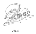
- the control valve 120 is shown in Figs 6-8 and comprises a stepped bore 121 formed in cover 90 with a piston 122 reciprocably slidable within the bore 121.
- the bore 121 has a smaller diameter portion 124 and a larger diameter portion 126 with a shoulder 128 therebetween.
- the piston 122 is a stepped piston having a smaller diameter portion 123 slidable within the smaller diameter portion 124 of the bore 121 and a larger diameter portion 125 accommodated within the larger diameter portion 126 of the bore 121.
- the piston 122 is biased away from the smaller diameter portion 124 of the bore 121 by a spring 127 acting between the shoulder 128 and the larger diameter portion 125 of the piston.
- the movement of the piston 122 away from the smaller diameter portion 124 of the bore is limited by an abutment 129 in the form of a circlip.
- the larger diameter portion 125 of the piston 122 has a plurality of axial passageways 131 connecting the front and back faces thereof.
- the smaller diameter portion 123 of the piston is hollow having an axially extending central passageway 132 connected to the outer surface thereof by radial passageways 133.
- the radial passageways are located in the smaller diameter portion at its end adjacent the larger diameter portion 125.
- the spring 127 biases the piston 122 towards the abutment with the circlip 129 as shown in Fig. 7.
- the pump 95 when the pump 95 generates lower fluid pressure, for example from a low speed differential of the type generated when turning, the low pressure fluid may pass through the passageways 131,133, and 132 and go to drain in the bottom of the housing 81. This diversion of low/medium pressure fluid prevents the operation of the actuator 104.
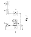
- valve 120 The operation of the valve 120 is shown schematically in Fig.5.
- the oil flow from the pump 95 passes to the valve 120 and to the actuator 104.
- the pressurized fluid at the valve 120 acts on the face of the piston 122 and may pass through the passageways to drain, ie the fluid reservoir in the housing 81.
- the oil pressure relief valve 135 limits the upper pressure acting within the actuator.
Landscapes
- Engineering & Computer Science (AREA)
- General Engineering & Computer Science (AREA)
- Mechanical Engineering (AREA)
- Physics & Mathematics (AREA)
- Fluid Mechanics (AREA)
- Arrangement And Driving Of Transmission Devices (AREA)
- Hydraulic Clutches, Magnetic Clutches, Fluid Clutches, And Fluid Joints (AREA)
- Retarders (AREA)
Abstract
Description
- This invention relates to a hydraulically operable coupling suitable for a vehicle transmission and in particular but not exclusively to vehicles having an all wheel drive facility, and to transmissions assemblies therefor.
- Four wheel drive vehicles normally operate in two wheel drive (2WD) and have part time alternative drive wheels that are controlled to operate when four wheel drive (4WD) is necessary.
- One conventional method of operation is a manual shift operated by the vehicle driver between 2WD and 4WD and this is normally achieved by means of a second gear stick located in the vehicle drive compartment.
- Another method of operation is for the vehicle to be provided with electronic and hydraulic sensors and controls which automatically split the torque output from the engine so as to supply torque to the driven wheels based on interrogation of the sensors by the control system.
- In WO 03/095256 the present applicant describes a vehicle transmission system in which a normally 2WD drive train also drives the alternative wheels under particular conditions. The control is purely mechanical having a hydraulically operable clutch of the type described in US-A-5310388.
- The clutch described in US-A-5310388 is a multi-plate friction clutch located in a housing containing transmission fluid and the clutch plates are clamped together by a hydraulic piston which is actuated by hydraulic pressure generated by pumped transmission fluid.
- The volume of pumped fluid and hence the clamping pressure on the clutch plates is related to the rotational speed difference between the housing and the output shaft which in turn is related to the rotational speed of the normally driven wheels (2WD) and the rotational speed of the alternative drive wheels in 4WD. For example, if the driven wheels spin then the speed differential between the normally driven and alternatively driven wheels triggers the system to engage the alternative wheels.
- A problem with purely mechanical all wheel drive systems arises during normal steering of a vehicle when the driven road wheels across an axle rotate at different speeds. If the rotation of any pair of wheels is locked this can result in wind up of the drive train.
- The present invention provides an improved vehicle final drive assembly which is particularly useful for vehicles having a primary wheel drive and a secondary wheel drive.
- According to a first aspect of the present invention there is provided a transmission coupling having a rotary input and at least one rotary output connected to the input through a clutch located within a casing, the clutch being operated by a hydraulic actuator actuated by hydraulic pressure generated by a pump which is operated by the speed differential between said input and outputs, and a valve responsive to the hydraulic pressure to permit actuation of the clutch above a predetermined hydraulic pressure, the valve being located in a wall of the casing.
- The valve is operable to dump pressurized hydraulic fluid to sump or drain when below said predetermined pressure and prevents or chokes the flow of fluid to drain above said pressure.
- The valve comprises a piston slidable within a bore formed in said wall and having passageways therein to permit the flow of hydraulic fluid therethrough unless said piston and bore co-operate to close the passageways.
- Preferably the valve comprises a stepped diameter piston housed in stepped diameter bore, the passageways comprising axial passageways in the larger diameter portion of the piston and both axial and radial passageways in the smaller diameter portion of the piston, and flow through the passageways is closed by the wall of the smaller diameter portion of the bore.
- The piston is biased to an open passageway condition by spring means.
- The casing acts as the rotary input and may be caused to rotate by means of an input shaft having a pinion thereon which engages a ring gear on the casing.
- The clutch preferably comprises a multi-plate friction clutch and the hydraulic pressure determines the clamping load on the clutch plates.
- The multi-plate clutch comprises a stack of annular friction plates having alternate plates rotationally fast with the casing and output shaft through their outer and inner peripheries respectively. The casing becomes rotationally fast with said output shaft when the clutch plates are compressed by a hydraulic actuator. The actuator piston is actuated by hydraulic pressure generated by a pump operated by differential rotational speed between the casing and output shaft.
- Another aspect of the invention provides a vehicle final drive assembly operable between a pair of wheels across an axle and comprising an input shaft, a pair of transmission couplings according to the first aspect of the invention, the two casings of which are rotatably connected in parallel to the input shaft, each coupling having its output shaft rotatably connected to said input shaft through the clutch and in use driving a respective wheel.
- Preferably the two casings are interconnected by a cross shaft and the input shaft engages with one of said casings.
- According to another aspect of the invention there is provided a transmission assembly for a motor vehicle and which includes a change speed transmission having an input shaft connectable to a vehicle engine, and a transmission main output shaft connected to a primary drive axle, and a final drive assembly according to a second aspect of the invention for a secondary drive axle.
- The final drive assembly is arranged with the two hydraulically operated coupling being spaced apart and located one on each side of the transmission assembly, preferably either side of the bell housing.
- A further aspect of the invention provides a motor vehicle having a final drive assembly according to the first aspect of the invention, driveably connected to either of a pair of front wheels or a pair of rear wheels not being on the primary drive axle.
- The invention will be described by way of example and with reference to the accompanying drawings in which:
- Fig.1
- is schematic view of a motor vehicle having a final drive assembly and transmission assembly having a coupling according to the present invention,
- Fig.2
- is a sectional side view of a transmission assembly showing the final drive input shaft and one coupling,
- Fig.3
- is a sectional view taken on the line III-III of Fig.2,
- Fig.4
- is a section through a coupling as is used in the final drive assembly of Fig. 2,
- Fig.5
- is a schematic layout hydraulic control system for the coupling,
- Fig.6
- is an exploded isometric showing an oil flow valve,
- Fig.7
- is an enlarged section showing the oil flow valve in an open condition, and
- Fig.8
- is an enlarged section showing the oil flow valve in a closed condition.
- With reference to Fig.1, there is shown a
motor vehicle 10 having an engine 11 arranged longitudinally of the vehicle. Atransmission assembly 13 is mounted on the rear of the engine and includes afinal drive assembly 14 which drives thefront wheels rear wheels rear wheels 17 & 18 which are driven by the transmissionmain shaft 51 via aconventional drive shaft 21 anddifferential unit 22 having the typical ring gear R and pinion P. - A secondary drive for the
front wheel 15 & 16 is taken off themain transmission shaft 51 viagears gear 54 drives aninput shaft 55 of the secondary final drive assembly. Thedrive shaft 55 is connected in parallel to a pair of hydraulically operatedcouplings respective wheels constant velocity joints 58 & 59. - Referring also to Figs. 2 & 3, the
transmission assembly 13 is described in detail in WO 03/095256 and will only be described in such detail as is necessary for an understanding of the present invention. Theassembly 13 includes agear box casing 23 which houses a plurality of change speed gears, as is well known, having a power input shaft which in use engages a drive coupling (not shown), typically a friction clutch, mounted on the rear of the engine 11 and enclosed inbell housing 24. Thebell housing 24 is secured to, or formed integrally with, thegear box casing 23. The change speed gears drive the transmissionmain drive shaft 51 extending rearwardly from the transmission assembly. - The secondary drive to the
front wheels 15 & 16 is substantially located in afinal drive housing 25 which in turn is mounted to thegear box casing 23 andbell housing 24. Thefinal drive assembly 14 and itshousing 25 are arranged so as to have a particular shape and configuration within the vehicle engine compartment so as to avoid other components mounted on the engine or within the engine compartment. - The
main drive shaft 51 connects with the secondarydrive input shaft 55 as previously described. The drivengear 54 is fixed to anend portion 55A of thesecondary input shaft 55 of thefinal drive assembly 14 to thefront wheels 15 & 16. The final secondarydrive input shaft 55 is rotatably supported in itshousing 25 to one side ofcasing 23 bybearings 75. Theshaft 55 is split into two portions, anupper portion 55A and alower portion 55B. The drivengear 54 is fixed to theupper portion 55A which extend substantially parallel with thetransmission shaft 51 and is connected to thelower portion 55B through a constant velocity joint 66. Thelower portion 55B of theinput shaft 55 is inclined downwardly and forwardly of the constant velocity joint 66. Apinion gear 67 on the lower end ofshaft 55 is drivably connected to adifferential system 80. - Splitting the
input shaft 55 into twoportions 55A & 55B linked via a universal joint enables the shaft and its portion of thehousing 25 to be routed and shaped to avoid other components within the engine compartment. - The
differential system 80 is mounted in ahousing 81, forming part of thefinal drive housing 25, and extending across the front lower portion of thegear box casing 23 andbell housing 24. Thehousing 81 is suitably sealed and contains hydraulic fluid for operation of the hydraulically operatedcouplings - The two
couplings 56 & 57 are mounted for coaxial rotation in thehousing 81 onbearings 82. Thecoupling 56 has acasing 86 of hollow construction which has abevel gear ring 87 extending around its outer surface which meshes with thepinion 67 to form the differential 80. Thecasing 86 is mounted in thehousing 81 bybearings 82 so that rotation of theshaft 55 causes thecasing 86 to rotate. Thecasing 86 is connected to a similar casing 88 of the second hydraulically operatedcoupling 57 by acoaxial cross shaft 89 so that thepinion 67 drives bothcasings 86 and 88 in parallel. The twocouplings coaxial half shafts wheels - The hydraulically operated
couplings casing 86 comprises acover 90 and a hollowcylindrical housing 101 enclosing a multi-plate friction clutch 93 operable in hydraulic fluid. The multi-plate clutch 93 comprises a stack ofannular friction plates 94 havingalternate plates casing 86, orclutch hub 102, through their outer and inner peripheries respectively. Thehub 102 is rotationally fast with thehalf shaft 91. Thecasing 86 becomes rotationally fast with thehalf shaft 91 when the clutch 93 is compressed by ahydraulic actuator 104. - The
hydraulic actuator 104 is actuated by hydraulic pressure generated by abi-directional oil pump 95. Theoil pump 95 comprises aninternal ring gear 96 mounted in the casing 88 for eccentric rotation relative to amulti-lobed impeller 97 mounted on thehalf shaft 91. Hydraulic fluid in the housing enters the pump viaapertures 98 in thecasing 86. - The hydraulic pressure generated by the
pump 95 operates theactuator piston 105 to cause engagement of the clutch when there is relative rotational movement between thehalf shaft 91 and thecasing 86. A more detailed explanation of the operation of the couplings is given in US 5310 388. - When a vehicle is driving normally along a highway, the primary drive is through the differential 22 and back axle. Since the front
wheel half shafts half shaft respective casing 86 or 88, then theoil pump 95 operates to develop sufficient pressure actuating thepiston 105 to clamp thefriction clutch 93, thereby transmitting drive from acasing 86 or 88 to a respective wheel. The drive is supplied to each wheel completely independently of the other wheel across the front axle. - However, if the vehicle is turning and the differential rotation is due to the turning action it is undesirable for the
piston 105 to clamp theclutch plates 94. In order to prevent operation of the clutch 93 in such circumstances, ahydraulic control valve 120 is provided to divert pressurized fluid from the pump away from theactuator 104 when the fluid pressure is below a predetermined pressure. - The
control valve 120 is shown in Figs 6-8 and comprises a steppedbore 121 formed incover 90 with apiston 122 reciprocably slidable within thebore 121. Thebore 121 has asmaller diameter portion 124 and alarger diameter portion 126 with ashoulder 128 therebetween. Thepiston 122 is a stepped piston having asmaller diameter portion 123 slidable within thesmaller diameter portion 124 of thebore 121 and alarger diameter portion 125 accommodated within thelarger diameter portion 126 of thebore 121. Thepiston 122 is biased away from thesmaller diameter portion 124 of thebore 121 by aspring 127 acting between theshoulder 128 and thelarger diameter portion 125 of the piston. The movement of thepiston 122 away from thesmaller diameter portion 124 of the bore is limited by anabutment 129 in the form of a circlip. - As is best seen in Figs 7 & 8, the
larger diameter portion 125 of thepiston 122 has a plurality ofaxial passageways 131 connecting the front and back faces thereof. Thesmaller diameter portion 123 of the piston is hollow having an axially extendingcentral passageway 132 connected to the outer surface thereof byradial passageways 133. The radial passageways are located in the smaller diameter portion at its end adjacent thelarger diameter portion 125. Thespring 127 biases thepiston 122 towards the abutment with thecirclip 129 as shown in Fig. 7. - In this condition, when the
pump 95 generates lower fluid pressure, for example from a low speed differential of the type generated when turning, the low pressure fluid may pass through the passageways 131,133, and 132 and go to drain in the bottom of thehousing 81. This diversion of low/medium pressure fluid prevents the operation of theactuator 104. - As the hydraulic pressure builds, during for example wheel slip, the pressure acting on the
larger diameter portion 125 of the piston eventually causes the piston to move against the spring bias and seat against theshoulder 128. In this condition as shown in Fig 8, theshoulder 128 closes thepassageways 131, and the small diameter bore 124 closes theradial passageways 133. All the pumped fluid pressure is now available for operation of the actuator. Any excess pressure may be drained through an oil pressure relief valve 135 (see Fig 5) in the wall of thepump 95. - The operation of the
valve 120 is shown schematically in Fig.5. The oil flow from thepump 95 passes to thevalve 120 and to theactuator 104. The pressurized fluid at thevalve 120 acts on the face of thepiston 122 and may pass through the passageways to drain, ie the fluid reservoir in thehousing 81. - If the flow to the drain is closed or choked, then the fluid pressure acting in the actuator rises. The oil
pressure relief valve 135 limits the upper pressure acting within the actuator.
Claims (13)
- A rotary transmission coupling (56) having a rotary input (86) and at least one rotary output (91) connected through a clutch (93) located within a casing (86), the clutch (93) being operable by a hydraulic actuator (104) responsive to hydraulic pressure generated by a pump (95) operated by the rotational speed differential between said input (86) and said output (91), and a valve (120) also responsive to the hydraulic pressure to permit actuation of the clutch (93) above a predetermined hydraulic pressure, characterised by the valve (120) being located in a wall (90) of the casing (86).
- A coupling as claimed in Claim 1, wherein the valve (120) is operable to divert pressurized hydraulic fluid from the actuator (104) when the hydraulic pressure is below said predetermined pressure.
- A coupling as claimed in claim 1 or 2, wherein the valve (120) comprises a piston (122) slidable within a bore (121) formed in said wall (90) and having passageways (131, 132, 133) therein to permit the flow of hydraulic fluid therethrough unless said piston (122) and bore (121) co-operate to close the passageways (131).
- A coupling as claimed in claim 3, wherein the valve (120) comprises a stepped diameter piston (122) housed in a stepped diameter bore (121), the passageways comprising axial passageways (131) in the larger diameter portion (125) of the piston (122) and radial passageways (133) in the smaller diameter portion (123) of the piston (122), the passageways being closed by interaction between the bore (121) and piston (122).
- A coupling as claimed in claim 3 or 4, wherein the piston (122) is biased by resilient means (127) to open the passageways.
- A coupling as claimed in any preceding claim, wherein said rotary input comprises the casing (86).
- A coupling as claimed in any preceding claim, wherein the clutch (93) comprises a multi-plate friction clutch and the hydraulic actuator (104) exerts a clamping load on the clutch plates (94).
- A coupling as claimed claim 7, wherein the multi-plate clutch comprises a stack of annular friction plates (94) having alternate plates rotationally fast with the casing (86) and output shaft (91) through their outer and inner peripheries respectively, the casing (86) becoming rotationally fast with said output shaft (91) when the clutch plates (94) are compressed by a hydraulic actuator (104).
- A coupling as claimed in any preceding claim, and further including a housing (81) in which the casing (86) and rotary output (91) are rotatably mounted, an input shaft (55) also rotatably mounted in the housing to engage the casing (86), and hydraulic fluid stored within the housing (81) for operation of the clutch (93).
- A vehicle final drive assembly operable between a pair of wheels across an axle and comprising an input shaft (55) and a pair of transmission couplings (56, 57) as claimed in any preceding claim, wherein the two casings (86) of said couplings are rotatably connected in parallel to the input shaft (55), each coupling (56, 57) having its output shaft (91, 92) rotatably connected to said input shaft (55) through the clutch (93) and in use driving a respective wheel.
- A drive assembly as claimed in claim 10, wherein the two casings (86) are interconnected by a cross shaft (89) and the input shaft (55) engages with one of said casings (86).
- A transmission assembly for a motor vehicle and which includes a change speed transmission (13) having an input shaft connectable to a vehicle engine (11), a transmission main output shaft (51) connected to a primary drive axle, and a final drive assembly as claimed in claim 10 or 11 connected to a secondary drive axle.
- A motor vehicle having a final drive assembly to either a pair of front wheels or a pair of rear wheels and which is a final drive assembly as claimed in claim 10 or 11.
Applications Claiming Priority (2)
| Application Number | Priority Date | Filing Date | Title |
|---|---|---|---|
| GBGB0414236.0A GB0414236D0 (en) | 2004-06-25 | 2004-06-25 | A hydraulically operable coupling |
| GB0414236 | 2004-06-25 |
Publications (3)
| Publication Number | Publication Date |
|---|---|
| EP1610019A2 true EP1610019A2 (en) | 2005-12-28 |
| EP1610019A3 EP1610019A3 (en) | 2007-04-25 |
| EP1610019B1 EP1610019B1 (en) | 2010-09-22 |
Family
ID=32800166
Family Applications (1)
| Application Number | Title | Priority Date | Filing Date |
|---|---|---|---|
| EP05253904A Expired - Lifetime EP1610019B1 (en) | 2004-06-25 | 2005-06-23 | A hydraulically operable coupling |
Country Status (3)
| Country | Link |
|---|---|
| EP (1) | EP1610019B1 (en) |
| DE (1) | DE602005023689D1 (en) |
| GB (1) | GB0414236D0 (en) |
Cited By (2)
| Publication number | Priority date | Publication date | Assignee | Title |
|---|---|---|---|---|
| EP2302246A1 (en) | 2009-09-29 | 2011-03-30 | Ford Global Technologies, LLC | A rotary transmission coupling |
| CN115467907A (en) * | 2022-11-15 | 2022-12-13 | 西南石油大学 | Drilling fluid displacement controlled drill string torque transmission and separation device and method thereof |
Citations (2)
| Publication number | Priority date | Publication date | Assignee | Title |
|---|---|---|---|---|
| US5310388A (en) | 1993-02-10 | 1994-05-10 | Asha Corporation | Vehicle drivetrain hydraulic coupling |
| WO2003095256A1 (en) | 2002-05-10 | 2003-11-20 | Ford Global Technologies, Llc. | A vehicle final drive assembly |
Family Cites Families (2)
| Publication number | Priority date | Publication date | Assignee | Title |
|---|---|---|---|---|
| US4421218A (en) * | 1981-02-02 | 1983-12-20 | Deere & Company | Relief valve means for rotatable fluid-pressure mechanisms |
| DE19539968C2 (en) * | 1995-10-27 | 2003-07-10 | Deere & Co | Valve, valve body and friction disc clutch |
-
2004
- 2004-06-25 GB GBGB0414236.0A patent/GB0414236D0/en not_active Ceased
-
2005
- 2005-06-23 EP EP05253904A patent/EP1610019B1/en not_active Expired - Lifetime
- 2005-06-23 DE DE602005023689T patent/DE602005023689D1/en not_active Expired - Lifetime
Patent Citations (2)
| Publication number | Priority date | Publication date | Assignee | Title |
|---|---|---|---|---|
| US5310388A (en) | 1993-02-10 | 1994-05-10 | Asha Corporation | Vehicle drivetrain hydraulic coupling |
| WO2003095256A1 (en) | 2002-05-10 | 2003-11-20 | Ford Global Technologies, Llc. | A vehicle final drive assembly |
Cited By (3)
| Publication number | Priority date | Publication date | Assignee | Title |
|---|---|---|---|---|
| EP2302246A1 (en) | 2009-09-29 | 2011-03-30 | Ford Global Technologies, LLC | A rotary transmission coupling |
| CN115467907A (en) * | 2022-11-15 | 2022-12-13 | 西南石油大学 | Drilling fluid displacement controlled drill string torque transmission and separation device and method thereof |
| CN115467907B (en) * | 2022-11-15 | 2023-03-03 | 西南石油大学 | Drilling fluid displacement controlled drill string torque transmission and separation device and method thereof |
Also Published As
| Publication number | Publication date |
|---|---|
| EP1610019A3 (en) | 2007-04-25 |
| GB0414236D0 (en) | 2004-07-28 |
| EP1610019B1 (en) | 2010-09-22 |
| DE602005023689D1 (en) | 2010-11-04 |
Similar Documents
| Publication | Publication Date | Title |
|---|---|---|
| EP0262434B1 (en) | Interaxle differential restriction device for vehicle four wheel drive systems | |
| USRE32565E (en) | Four-wheel vehicle drive system | |
| EP0524707B1 (en) | Transmission system for a two and four-wheel drive motor vehicle | |
| EP0390362B1 (en) | Power transmission system of a motor vehicle | |
| US6199380B1 (en) | Axle driving apparatus | |
| US6487924B2 (en) | Transmission assembly for working vehicles | |
| US5215506A (en) | Electronically controlled differential limiting system | |
| US6199653B1 (en) | Four-wheel driven vehicle | |
| AU2006202641B2 (en) | Improved coupling device independent of differential speed | |
| US6935986B2 (en) | Two speed gearbox | |
| US4531421A (en) | Transfer case oil pump | |
| US5338266A (en) | Differential transmission device and viscous coupler, especially for a motor vehicle | |
| EP1610019B1 (en) | A hydraulically operable coupling | |
| JP2006077985A (en) | Coupling device | |
| EP1503916B1 (en) | A vehicle final drive assembly | |
| CN100558576C (en) | Drive system for vehicle powertrain and vehicle comprising same | |
| US4907472A (en) | Power transmitting system for a four-wheel drive vehicle | |
| CN102057177B (en) | Transmission gear engagement mechanism and method of operation | |
| US4509626A (en) | Hydraulically actuated high torque, quick engagement clutch assembly | |
| EP1967405B1 (en) | A final drive assembly for a vehicule | |
| EP1956260B1 (en) | A hydraulically operable coupling | |
| EP1834828B1 (en) | A vehicle transmission assembly | |
| US10774912B2 (en) | Electronic limited slip coupling having bolt on configuration | |
| EP2302246A1 (en) | A rotary transmission coupling | |
| JPH09184559A (en) | Work vehicle transmission |
Legal Events
| Date | Code | Title | Description |
|---|---|---|---|
| PUAI | Public reference made under article 153(3) epc to a published international application that has entered the european phase |
Free format text: ORIGINAL CODE: 0009012 |
|
| AK | Designated contracting states |
Kind code of ref document: A2 Designated state(s): AT BE BG CH CY CZ DE DK EE ES FI FR GB GR HU IE IS IT LI LT LU MC NL PL PT RO SE SI SK TR |
|
| AX | Request for extension of the european patent |
Extension state: AL BA HR LV MK YU |
|
| RAP1 | Party data changed (applicant data changed or rights of an application transferred) |
Owner name: FORD GLOBAL TECHNOLOGIES, LLC. Owner name: COUNTRYTRAC LIMITED |
|
| PUAL | Search report despatched |
Free format text: ORIGINAL CODE: 0009013 |
|
| AK | Designated contracting states |
Kind code of ref document: A3 Designated state(s): AT BE BG CH CY CZ DE DK EE ES FI FR GB GR HU IE IS IT LI LT LU MC NL PL PT RO SE SI SK TR |
|
| AX | Request for extension of the european patent |
Extension state: AL BA HR LV MK YU |
|
| 17P | Request for examination filed |
Effective date: 20071025 |
|
| 17Q | First examination report despatched |
Effective date: 20071129 |
|
| AKX | Designation fees paid |
Designated state(s): DE GB TR |
|
| GRAP | Despatch of communication of intention to grant a patent |
Free format text: ORIGINAL CODE: EPIDOSNIGR1 |
|
| GRAS | Grant fee paid |
Free format text: ORIGINAL CODE: EPIDOSNIGR3 |
|
| GRAA | (expected) grant |
Free format text: ORIGINAL CODE: 0009210 |
|
| AK | Designated contracting states |
Kind code of ref document: B1 Designated state(s): DE GB TR |
|
| REG | Reference to a national code |
Ref country code: GB Ref legal event code: FG4D |
|
| REF | Corresponds to: |
Ref document number: 602005023689 Country of ref document: DE Date of ref document: 20101104 Kind code of ref document: P |
|
| PLBE | No opposition filed within time limit |
Free format text: ORIGINAL CODE: 0009261 |
|
| STAA | Information on the status of an ep patent application or granted ep patent |
Free format text: STATUS: NO OPPOSITION FILED WITHIN TIME LIMIT |
|
| 26N | No opposition filed |
Effective date: 20110623 |
|
| REG | Reference to a national code |
Ref country code: DE Ref legal event code: R097 Ref document number: 602005023689 Country of ref document: DE Effective date: 20110623 |
|
| PGFP | Annual fee paid to national office [announced via postgrant information from national office to epo] |
Ref country code: DE Payment date: 20200518 Year of fee payment: 16 |
|
| REG | Reference to a national code |
Ref country code: DE Ref legal event code: R119 Ref document number: 602005023689 Country of ref document: DE |
|
| PG25 | Lapsed in a contracting state [announced via postgrant information from national office to epo] |
Ref country code: DE Free format text: LAPSE BECAUSE OF NON-PAYMENT OF DUE FEES Effective date: 20220101 |
|
| PGFP | Annual fee paid to national office [announced via postgrant information from national office to epo] |
Ref country code: GB Payment date: 20240509 Year of fee payment: 20 |
|
| PGFP | Annual fee paid to national office [announced via postgrant information from national office to epo] |
Ref country code: TR Payment date: 20240514 Year of fee payment: 20 |
|
| PG25 | Lapsed in a contracting state [announced via postgrant information from national office to epo] |
Ref country code: GB Free format text: LAPSE BECAUSE OF EXPIRATION OF PROTECTION Effective date: 20250622 |
|
| REG | Reference to a national code |
Ref country code: GB Ref legal event code: PE20 Expiry date: 20250622 |