EP1609979A2 - Injector for fuel injection unit - Google Patents
Injector for fuel injection unit Download PDFInfo
- Publication number
- EP1609979A2 EP1609979A2 EP05012225A EP05012225A EP1609979A2 EP 1609979 A2 EP1609979 A2 EP 1609979A2 EP 05012225 A EP05012225 A EP 05012225A EP 05012225 A EP05012225 A EP 05012225A EP 1609979 A2 EP1609979 A2 EP 1609979A2
- Authority
- EP
- European Patent Office
- Prior art keywords
- pressure fuel
- low
- longitudinal hole
- injector
- fuel passage
- Prior art date
- Legal status (The legal status is an assumption and is not a legal conclusion. Google has not performed a legal analysis and makes no representation as to the accuracy of the status listed.)
- Granted
Links
- 239000000446 fuel Substances 0.000 title claims abstract description 162
- 238000002347 injection Methods 0.000 title claims abstract description 33
- 239000007924 injection Substances 0.000 title claims abstract description 33
- 230000005540 biological transmission Effects 0.000 claims abstract description 26
- 238000007599 discharging Methods 0.000 claims description 4
- 238000009825 accumulation Methods 0.000 description 7
- 238000006073 displacement reaction Methods 0.000 description 6
- 230000007423 decrease Effects 0.000 description 5
- 238000000034 method Methods 0.000 description 5
- 230000008569 process Effects 0.000 description 3
- 238000009966 trimming Methods 0.000 description 3
- 238000004891 communication Methods 0.000 description 2
- 230000003247 decreasing effect Effects 0.000 description 2
- 238000003754 machining Methods 0.000 description 2
- 230000000149 penetrating effect Effects 0.000 description 2
- 239000000919 ceramic Substances 0.000 description 1
- 230000008859 change Effects 0.000 description 1
- 238000002485 combustion reaction Methods 0.000 description 1
- 230000000994 depressogenic effect Effects 0.000 description 1
- 238000010586 diagram Methods 0.000 description 1
- 230000005611 electricity Effects 0.000 description 1
- 239000012530 fluid Substances 0.000 description 1
- 239000002828 fuel tank Substances 0.000 description 1
- 230000006872 improvement Effects 0.000 description 1
- 238000009434 installation Methods 0.000 description 1
- 230000004044 response Effects 0.000 description 1
- 238000007789 sealing Methods 0.000 description 1
Images


Classifications
-
- F—MECHANICAL ENGINEERING; LIGHTING; HEATING; WEAPONS; BLASTING
- F02—COMBUSTION ENGINES; HOT-GAS OR COMBUSTION-PRODUCT ENGINE PLANTS
- F02M—SUPPLYING COMBUSTION ENGINES IN GENERAL WITH COMBUSTIBLE MIXTURES OR CONSTITUENTS THEREOF
- F02M61/00—Fuel-injectors not provided for in groups F02M39/00 - F02M57/00 or F02M67/00
- F02M61/16—Details not provided for in, or of interest apart from, the apparatus of groups F02M61/02 - F02M61/14
- F02M61/168—Assembling; Disassembling; Manufacturing; Adjusting
-
- F—MECHANICAL ENGINEERING; LIGHTING; HEATING; WEAPONS; BLASTING
- F02—COMBUSTION ENGINES; HOT-GAS OR COMBUSTION-PRODUCT ENGINE PLANTS
- F02M—SUPPLYING COMBUSTION ENGINES IN GENERAL WITH COMBUSTIBLE MIXTURES OR CONSTITUENTS THEREOF
- F02M47/00—Fuel-injection apparatus operated cyclically with fuel-injection valves actuated by fluid pressure
- F02M47/02—Fuel-injection apparatus operated cyclically with fuel-injection valves actuated by fluid pressure of accumulator-injector type, i.e. having fuel pressure of accumulator tending to open, and fuel pressure in other chamber tending to close, injection valves and having means for periodically releasing that closing pressure
- F02M47/025—Hydraulically actuated valves draining the chamber to release the closing pressure
-
- F—MECHANICAL ENGINEERING; LIGHTING; HEATING; WEAPONS; BLASTING
- F02—COMBUSTION ENGINES; HOT-GAS OR COMBUSTION-PRODUCT ENGINE PLANTS
- F02M—SUPPLYING COMBUSTION ENGINES IN GENERAL WITH COMBUSTIBLE MIXTURES OR CONSTITUENTS THEREOF
- F02M63/00—Other fuel-injection apparatus having pertinent characteristics not provided for in groups F02M39/00 - F02M57/00 or F02M67/00; Details, component parts, or accessories of fuel-injection apparatus, not provided for in, or of interest apart from, the apparatus of groups F02M39/00 - F02M61/00 or F02M67/00; Combination of fuel pump with other devices, e.g. lubricating oil pump
- F02M63/0012—Valves
- F02M63/0031—Valves characterized by the type of valves, e.g. special valve member details, valve seat details, valve housing details
- F02M63/0045—Three-way valves
-
- F—MECHANICAL ENGINEERING; LIGHTING; HEATING; WEAPONS; BLASTING
- F02—COMBUSTION ENGINES; HOT-GAS OR COMBUSTION-PRODUCT ENGINE PLANTS
- F02M—SUPPLYING COMBUSTION ENGINES IN GENERAL WITH COMBUSTIBLE MIXTURES OR CONSTITUENTS THEREOF
- F02M2200/00—Details of fuel-injection apparatus, not otherwise provided for
- F02M2200/70—Linkage between actuator and actuated element, e.g. between piezoelectric actuator and needle valve or pump plunger
- F02M2200/703—Linkage between actuator and actuated element, e.g. between piezoelectric actuator and needle valve or pump plunger hydraulic
Definitions
- the present invention relates to an injector for a fuel injection unit for an internal combustion engine and especially relates to the injector suitable for a common rail type fuel injection unit.
- a common rail type fuel' injection system which has a common rail identical to respective cylinders and accumulating high-pressure fuel therein for a diesel engine.
- the high-pressure fuel is pressure-fed from a fuel supply pump, adjusted to be a predetermined pressure in the common rail and injected at predetermined timings into the respective cylinders by driving injectors.
- the injectors configured for use with the common rail injects fuel through injection holes by lifting a nozzle needle up and down.
- An actuator drives a control valve to increase and decrease a backpressure of the nozzle needle to lift the nozzle needle up and down.
- a structure of the injectors for the common rail type fuel injection system is disclosed, for example, in JP-2002-257002-A and its counterpart US-6,840,466-B2.
- the structure is configured to drive the control valve by amplifying a displacement of the actuator by a hydraulic power transmission unit.
- the hydraulic power transmission unit comprises a first piston having a large diameter, a second piston having a small diameter and a displacement amplifying chamber accumulating actuation fluid in a chamber formed between the first and second pistons.
- the hydraulic power transmission unit controls the backpressure of the nozzle needle by communicating a backpressure chamber of the nozzle needle selectively to a low-pressure fuel passage or a high-pressure fuel passage.
- the actuator is realized by a piezoelectric actuator, for example, which has a fine response to deliver high performance in fuel injection control.
- An injector body is provided with the low-pressure fuel passage for collecting and discharging the leakage fuel and the high-pressure fuel passage in which the high-pressure fuel is supplied from the common rail.
- These fuel passages can be formed, for example, at a side of the actuator and the hydraulic power transmission unit disposed along a center axis of the injector body.
- FIGS. 3A and 3B Current demand to raise fuel injection pressure exposes the high-pressure fuel passage to larger stress and requires to increase strength of a periphery of the high-pressure fuel passage.
- it is considered, for example, to shift center axes of the actuator and the hydraulic power transmission unit eccentrically to the center axis of the injector body as shown in FIGS. 3A and 3B.
- an injection nozzle portion 103 is disposed at a lower end portion of the injector body B.
- a nozzle needle 6 is disposed slidably in and coaxially with the injector body B. As shown in FIG.
- the injector body B has a longitudinal hole 31 for installing the actuator 3 and the hydraulic power transmission unit 4 eccentrically to the injector body B and a high-pressure fuel passage 1 penetrating through a thick wall portion at a side of the longitudinal hole 31.
- Low-pressure fuel passages 2 are formed at plural positions in the thick wall portion around the longitudinal hole 31 to be separated from the high-pressure fuel passage 1.
- the actuator 3 and the hydraulic power transmission unit 4 form a driving portion 101 to drive a control valve portion 102 disposed below the driving portion 101.
- the eccentric arrangement of the actuator 3 and the hydraulic power transmission unit 4 extends a space at a side of these components.
- An engine head H on which the injector body B is mounted limits an outer diameter of the injector body B.
- the low-pressure fuel passage 2 In order to dispose the longitudinal hole 31 for installing actuator 3 and the hydraulic power transmission unit 4 and the high-pressure fuel passage 1 respectively having enough diameters and wall thicknesses, the low-pressure fuel passage 2 must be formed thin as shown in the cross-sectional view of FIG. 3B. Further, a complicated work is necessary to form a relatively long low-pressure fuel passage 2' connecting the low-pressure fuel passage 2 to a fuel drain port 21 at an upper side portion of the injector body B to discharge the leakage fuel to outside.
- the present invention has an object to provide an injector for a fuel injection unit having a compact size and sufficient strength by securing enough diameters and wall thicknesses for an installation hole installing an actuator and a hydraulic power transmission unit and for the high-pressure fuel passage and having a low-pressure fuel passage which can be formed in a simple work process.
- the injector for a fuel injection unit has an injection body member, an actuator and a hydraulic power transmission unit.
- the hydraulic power transmission unit transmits an actuating force of the actuator to a valve for controlling a fuel injection.
- the injector is characterized in further comprising a longitudinal hole, a high-pressure fuel passage, a low-pressure fuel chamber and a low-pressure fuel passage groove.
- the longitudinal hole is formed in the injector body member and installs the actuator and the hydraulic power transmission unit therein.
- the high-pressure fuel passage is formed in the injector body member at a radial side of the longitudinal hole to supply a high-pressure fuel for the fuel injection.
- the low-pressure fuel chamber is provided in the longitudinal hole and communicated to an outer leakage passage.
- the low-pressure fuel passage groove is formed on an inner circumferential face of the longitudinal hole to extend in a longitudinal direction of the longitudinal hole and to communicate with the low-pressure fuel chamber and a low-pressure fuel passage for discharging a leakage fuel leaked in the injector.
- FIG. 1A is a diagram showing an entire structure of the injector I.
- FIG. 1B is a cross-sectional view taken along a line IB - IB in FIG. 1A.
- the injector I is fixed in a mounting hole provided in a cylinder head H of an engine to inject fuel into respective cylinders.
- the injector I comprises a driving portion 101 having a piezoelectric actuator 3 and a hydraulic power transmission unit 4, a control valve portion 102 having a valve 5 with three-way valve structure and an injection nozzle portion 103 having a nozzle needle 6.
- the driving portion 101 has an injector body B1, which is an injector body member, to install the piezoelectric actuator 3 and the hydraulic power transmission unit 4 therein.
- a valve body B3 of the control valve portion 102 is disposed at a lower end side of the injector body B1 to interpose a passage forming member B2 therebetween.
- a nozzle body B5 of the injection nozzle portion 103 is disposed at a lower end side of the valve body B3 to interpose a passage forming member B4 therebetween.
- These body members B1 to B5 are fastened and fixed to each other in oil-tight state by retainers (not shown).
- the injector I has a high-pressure fuel passage 1 formed in a longitudinal direction thereof for fuel supply.
- the high-pressure fuel passage 1 is connected via a fuel supply port 11 opening at an upper side portion of the injector body B1 to an outer common rail (not shown).
- the common rail accumulates fuel pressure-fed from a high-pressure fuel supply pump at a predetermined high pressure corresponding to an injection pressure.
- a fuel drain port 21 opens at an upper side portion of the injector body B1 to return leakage fuel from the injector I via a leakage fuel passage (not shown) to a fuel tank (not shown).
- the injection nozzle portion 103 retains a nozzle needle 6 having a stepped shape slidably in a cylinder provided in the body member B5.
- a space around a lower small diameter portion of the nozzle needle 6 forms an oil accumulation chamber 62.
- High-pressure fuel is supplied from a common rail to the oil accumulation chamber 62 through a high-pressure fuel passage 1 connected to a side wall of the oil accumulation chamber 62.
- a lower center portion of the body member B5 has a sac portion 63 and injection holes 64 to penetrate a wall forming the sac portion 63.
- a conically shaped tip portion of the nozzle needle 6 seats on a nozzle seat 65 provided at a boundary portion between the oil accumulation chamber 62 and the sac portion 63 to shut the sac portion 63 and interrupt fuel supply from the oil accumulation chamber 62 to the injection holes 64.
- Fuel injection commences by a lift up of the nozzle needle 6 apart from the nozzle seat 65 to open the sac portion 63.
- a space defined by an upper end face of the nozzle needle 6 and an inner wall face of the cylinder forms a control chamber 61 for controlling a backpressure of the nozzle needle 6.
- the control chamber 61 is supplied with fuel as control oil from a passage 12 connected to the high-pressure fuel passage 1 through a valve chamber of the control valve portion 102, a passage 13 and an orifice 14 to generate the backpressure of the nozzle needle 6. Further, the control chamber 61 is connected via an orifice 15 to the high-pressure fuel passage 1 at any time.
- the backpressure pushes the nozzle needle 6 downward together with a spring 66 installed in the control chamber 61 to urge the nozzle needle 6 in a valve closing direction.
- High-pressure fuel in the oil accumulation chamber 62 pushes the nozzle needle 6 upward to urge the nozzle needle 6 in a valve opening direction.
- the control valve portion 102 has a valve 5 having three-way valve structure.
- a large diameter valve portion of the valve 5 is disposed in a valve chamber 51 connected to the control chamber 61 at any time.
- a lower portion of the valve 5 is shaped as sort of a piston and slides in a cylinder formed in the body member B3.
- a lower end portion of the cylinder is a spring chamber 54 for installing a spring 55 urging the valve 5 upward.
- the valve chamber 51 has a low-pressure side seat 52 on a top face thereof and a high-pressure side seat 53 on a bottom face thereof.
- the valve 5 selectively seats on any one of these seats 52, 53.
- the large diameter valve portion of the valve 5 has two conical faces for seating on these seats 52, 53.
- Each of the passage forming member B2 and the body member B3 is provided with a low-pressure fuel passage 23 penetrating an approximately center portion thereof in a longitudinal direction.
- the low-pressure fuel passage 23 is connected via a passage 24 to the spring chamber 54 and via a passage 25 to a passage downstream the low-pressure side seat 52.
- the passage 24 discharges fuel in the spring chamber 54 therethrough to smooth a valve opening motion of the valve 5.
- the control valve portion 102 discharges fuel via these passages 24, 25 to the low-pressure fuel passage 23.
- leakage fuel from the control chamber 61 at an upper end portion of the injection nozzle portion 103 also flows into the fuel passage 23.
- valve 5 In accordance with a seat position of the valve 5 switched by the driving portion 101, pressure in the control chamber 61 connected to the valve chamber 51, that is, the backpressure of the nozzle needle 6 increases and decreases.
- the control chamber 61 When the valve 5 is at an upper end position to close the low-pressure side seat 52, the control chamber 61 is connected via the high-pressure side seat 53 to the high-pressure fuel passage1 to act hydraulic pressure to the nozzle needle 6 in the valve closing direction.
- the control chamber 61 When the valve 5 is pushed down to close the high-pressure side seat 53 to open the low-pressure side seat 52, the control chamber 61 is connected via the low-pressure side seat 52 to the low-pressure fuel passage 2 to decrease the backpressure of the nozzle needle 6.
- the driving portion 101 transmits the driving force of the piezoelectric actuator 3 as an actuator to the valve 5 in the control valve portion 102 with the hydraulic power transmission unit 4.
- the piezoelectric actuator 3 is installed in an upper portion of the longitudinal hole 31 formed in the injector body B1.
- the hydraulic power transmission unit 4 is installed in a lower portion of the longitudinal hole 31.
- the piezoelectric actuator 3 has a conventional structure including a piezostack in which piezo-ceramic layers such as PZT and electrode layers are alternately stacked.
- the piezoelectric actuator 3 extends and shrinks in the stacking direction of the layers (up and down direction) and is charged and discharged by a driving circuit (not shown).
- the injector body B1 has an approximately cylindrical shape and the longitudinal hole 31 is provided eccentric to the center axis of the injector body B.
- the injector body B1 has a thick wall portion at a side of the longitudinal hole 31.
- the high-pressure fuel passage 1 is provided approximately at a center of the thick wall portion. This is to secure enough wall thickness around the high-pressure fuel passage 1.
- each of the high-pressure fuel passage 1, the longitudinal hole 31 and the injector body B1 is disposed approximately in parallel to the center axis of the injector body B.
- the longitudinal hole 31 and the piezoelectric actuator 3 form a low-pressure fuel chamber 22 having an annular shape therebetween.
- a passage 27 connected to the fuel drain port 21 opens to the low-pressure fuel chamber 22.
- the hydraulic power transmission unit 4 includes a large diameter piston 42 and a small diameter piston 44 slidably installed in the cylindrically shaped cylinder member 41 and a oil-tight chamber 43 accumulating actuating oil between the pistons 42, 44.
- the large diameter piston 42 has an upper flange portion protruding above the cylinder member 41 to be in contact with a lower end face of the piezoelectric actuator 3.
- a spring 45 is interposed between the flange portion and an upper end face of the cylinder member 41 to apply a predetermined primary load via the large diameter piston 42 to the piezoelectric actuator 3.
- the large diameter piston 42 slides upward and downward in contact with and integrally with the piezoelectric actuator 3 in accordance with an extension and shrinkage of the piezoelectric actuator 3.
- a valve spring 46 is disposed in the oil-tight chamber 43 to urge the small diameter piston 44 downward.
- the small diameter piston 44 has a pin-shaped lower portion extending into the passage-forming member B2 to be in contact with an upper end face of the valve 5 in the valve chamber 51.
- an annular-shaped passage is formed around the pin-shaped lower portion of the small diameter piston 44 to be connected to the low-pressure side seat 52.
- the passage 25 connected to the low-pressure fuel passage 23 opens to the annular-shaped passage.
- An upper end of the low-pressure fuel passage 23 is connected to a low-pressure fuel passage groove 26 opening to a lower end face of the injector body B1.
- the low-pressure fuel passage groove 26 includes a plurality of depressed grooves 32 having approximately half-round cross-section formed to overlap with a periphery of the longitudinal hole 31 to be the low-pressure fuel passage 23.
- the low-pressure fuel passage groove 26 is formed at a periphery of the longitudinal hole 31 at a side of the high-pressure fuel passage 1, that is, approximately at a radial center portion of the injector body B1 in which relatively large wall thickness can be spared.
- the high-pressure fuel passage 1 is provided with a surrounding wall with enough thickness.
- an upper end of the low-pressure fuel passage groove 26 is disposed higher than the upper end face of the cylinder member 41 installed in the longitudinal hole 31.
- the upper end of the low-pressure fuel passage groove 26 opens to the low-pressure fuel chamber 22 to form a flow path from the low-pressure fuel passage 23 via the low-pressure fuel passage groove 26, the low-pressure fuel chamber 23 to the low-pressure fuel drain port 21.
- FIG. 1A depicts a state in which the piezoelectric actuator 3 is electrically discharged and shrunk and the valve 5 is at an upper end position to close the low-pressure side seat 52.
- a communication between the passage 25 connected to the low-pressure fuel passage 23 and the valve chamber 51 is interrupted, so that the pressure in the control chamber 61 is increased by fuel flowing from the high-pressure fuel passage 1 via the orifice 15, the passage 12, valve chamber 51, the passage 13 or the orifice 14.
- the pressure in the control chamber 61 and the restitutive force of the spring 66 seats the nozzle needle 6 onto the nozzle seat 65 to interrupt a communication between the injection hole 64 and the oil accumulation chamber 62.
- the piezoelectric actuator 3 In this state, by supplying current to the piezoelectric actuator 3, the piezoelectric actuator 3 extends to move the large diameter piston 42 downward and to pressurize the actuating oil (light oil in this embodiment) in the oil-tight chamber 43. The pressure of the actuating oil moves the small diameter piston downward to push the valve 5 down.
- the control chamber 61 becomes communicated via the valve chamber 51, the low-pressure side seat 52, the passage 25 with the low-pressure fuel passage 23 to decrease the pressure in the control chamber 4.
- a force urging the nozzle needle 5 downward exceeds a force urging the nozzle needle 5 upward, the nozzle needle 5 lifts off the valve seat to start fuel injection.
- the injector body B1 is provided with the longitudinal hole 31 installing the piezoelectric actuator 3 and the displacement transmission unit 4 to be eccentric thereto, an enough space is spared at the side of the longitudinal hole 31 to form the high-pressure fuel passage 1 therein.
- a space in the longitudinal hole 31 is used as the low-pressure fuel chamber 22 forming a part of the passage for discharging the leakage fuel and the groove 32 integrally provided at the periphery of the longitudinal hole 31 as the low-pressure fuel groove 22 connected to the low-pressure fuel passage for collecting the leakage fuel from the control valve portion 102 and the fuel injection nozzle portion 103, it is easier to spare and form a sectional area of the low-pressure fuel passage (the sectional area of the low-pressure fuel passage groove 26) relative to the structure shown in FIGS. 3A and 3B. Further, the low-pressure fuel passage groove 26 may be short as long as it is communicated with the low-pressure fuel chamber 23.
- the radial centers of the high-pressure fuel passage 1, the longitudinal hole 31 and the injector body B1 on an imaginary identical line and to dispose a plurality of the low-pressure fuel passage grooves 26 symmetrically at an upper and lower sides with respect to the imaginary identical line to spare enough thickness of the respective passages and secure enough strength of the periphery of the respective passages.
- This structure of the low-pressure fuel passage groove 26 can be formed by an ordinary boring work. For example, a round shaped bore is worked to form the low-pressure fuel passage groove 26 at first, then the longitudinal hole 31 is formed to overlap with the bore formed for the low-pressure fuel passage groove 26. It is also possible to form the low-pressure fuel passage groove 26 by a subsequent work process such as electric discharge machining.
- the shape and size of the low-pressure fuel passage groove 26 is determined in accordance with a necessary sectional area of the flow passage and so on. Specifically, in the conventional structure as shown in FIG. 3B, a bore worked for the low-pressure fuel passage 2 has a diameter of 2.2 mm and a depth of 100 mm. In the structure of the present invention as shown in FIG. 1B, the diameter of the round shaped bore, a part of which the low-pressure fuel passage groove 2, has a diameter of 3.5 mm and a depth of 45 mm.
- the ratio of ⁇ (the indicator in the conventional structure)/(the indicator of the present invention) ⁇ equals 1/3.5, which shows an improvement in workability in the present invention.
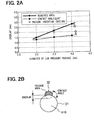
- FIG. 2A shows a relation between the diameter of the low-pressure fuel passage and the overlap degree to secure an equivalent sectional area of the flow path relative to a conventional one.
- the diameter of the low-pressure fuel passage is the diameter of the round bore, a part of which is the groove 32 in FIG. 2B
- the overlap degree is the depth of an overlap portion between the round bore and the longitudinal hole 31.
- a solid line in FIG. 2A is the overlapped depth in a case that the sectional area of the flow path is equivalent to the conventional one. If the overlapped depth is decreased, the sectional area of the flow path becomes larger than the conventional one.
- a contact angle shown in the figure (the angle at which tangential lines of the longitudinal hole 31 and the low-pressure fuel passage groove 26 meet at an intersection thereof) becomes smaller to cause the trimming burrs in the work process.
- a dotted line in the FIG. 2A shows the overlap degree when the contact angle is 90 degrees. It is desirable to set the contact angle equal to or larger than 90 degrees to restrict the generation of the trimming burrs, by setting the overlapped depth larger than this overlap degree.
- the diameter of the low-pressure fuel passage and the overlap depth are disposed between the solid line and the dotted line in the figure.
- a round bore, a part of which is the low-pressure fuel passage groove 2 has a diameter of 3.5 mm
- a piezoelectric actuator is applied in the above-described embodiment.
- An actuator in the present invention is not limited to the piezoelectric actuator.
- Magneto-striction actuator and the like may be applied which has a magneto-striction element generating a displacement by flowing electricity similar to the piezoelectric actuator.
- the invention may have other structures to open and close the nozzle needle by other methods. It is natural to change the structures such as the control valve portion, the injection nozzle portion and others.
- An injector body (B1) is provided with a longitudinal hole (31) eccentrically to the injector body (B1) to install an actuator (3) and a hydraulic power transmission unit (4).
- a high-pressure fuel passage (1) is disposed in a thick wall portion formed at a side of the longitudinal hole (31).
- a space in the longitudinal hole (31) functions as a low-pressure fuel chamber (22) and connected to an outer leakage passage.
- a groove (32) is formed on an inner side wall of the hole 31 to be connected to a low-pressure fuel passage (23) to provide a low-pressure fuel passage groove (26) to discharge leakage fuel from an injection nozzle portion (103) and a control valve portion (102). It is easy to machine the groove (32) integral with the longitudinal hole (31) and to secure strength of a periphery of the high-pressure fuel passage (1).
Landscapes
- Engineering & Computer Science (AREA)
- Chemical & Material Sciences (AREA)
- Combustion & Propulsion (AREA)
- Mechanical Engineering (AREA)
- General Engineering & Computer Science (AREA)
- Physics & Mathematics (AREA)
- Fluid Mechanics (AREA)
- Manufacturing & Machinery (AREA)
- Fuel-Injection Apparatus (AREA)
Abstract
Description
- The present invention relates to an injector for a fuel injection unit for an internal combustion engine and especially relates to the injector suitable for a common rail type fuel injection unit.
- A common rail type fuel' injection system is known which has a common rail identical to respective cylinders and accumulating high-pressure fuel therein for a diesel engine. The high-pressure fuel is pressure-fed from a fuel supply pump, adjusted to be a predetermined pressure in the common rail and injected at predetermined timings into the respective cylinders by driving injectors. Generally, the injectors configured for use with the common rail injects fuel through injection holes by lifting a nozzle needle up and down. An actuator drives a control valve to increase and decrease a backpressure of the nozzle needle to lift the nozzle needle up and down.
- A structure of the injectors for the common rail type fuel injection system is disclosed, for example, in JP-2002-257002-A and its counterpart US-6,840,466-B2. The structure is configured to drive the control valve by amplifying a displacement of the actuator by a hydraulic power transmission unit. The hydraulic power transmission unit comprises a first piston having a large diameter, a second piston having a small diameter and a displacement amplifying chamber accumulating actuation fluid in a chamber formed between the first and second pistons. The hydraulic power transmission unit controls the backpressure of the nozzle needle by communicating a backpressure chamber of the nozzle needle selectively to a low-pressure fuel passage or a high-pressure fuel passage. The actuator is realized by a piezoelectric actuator, for example, which has a fine response to deliver high performance in fuel injection control.
- In the injector is leakage fuel leaked through high-pressure sealing portions of respective components and a sliding portion of the control valve and leakage fuel discharged from the control chamber for applying the backpressure to the nozzle needle to start fuel injection. An injector body is provided with the low-pressure fuel passage for collecting and discharging the leakage fuel and the high-pressure fuel passage in which the high-pressure fuel is supplied from the common rail. These fuel passages can be formed, for example, at a side of the actuator and the hydraulic power transmission unit disposed along a center axis of the injector body.
- Current demand to raise fuel injection pressure exposes the high-pressure fuel passage to larger stress and requires to increase strength of a periphery of the high-pressure fuel passage. In accordance with the demand, it is considered, for example, to shift center axes of the actuator and the hydraulic power transmission unit eccentrically to the center axis of the injector body as shown in FIGS. 3A and 3B. In FIG. 3A, an
injection nozzle portion 103 is disposed at a lower end portion of the injector body B.A nozzle needle 6 is disposed slidably in and coaxially with the injector body B. As shown in FIG. 3B, the injector body B has alongitudinal hole 31 for installing theactuator 3 and the hydraulicpower transmission unit 4 eccentrically to the injector body B and a high-pressure fuel passage 1 penetrating through a thick wall portion at a side of thelongitudinal hole 31. Low-pressure fuel passages 2 are formed at plural positions in the thick wall portion around thelongitudinal hole 31 to be separated from the high-pressure fuel passage 1. Theactuator 3 and the hydraulicpower transmission unit 4 form adriving portion 101 to drive acontrol valve portion 102 disposed below thedriving portion 101. - In the structure as described above, the eccentric arrangement of the
actuator 3 and the hydraulicpower transmission unit 4 extends a space at a side of these components. Thus, it is possible to increase strength of the injector body B by disposing the high-pressure fuel passage 1 in the space to spare a relatively thick wall around the high-pressure fuel passage 1. An engine head H on which the injector body B is mounted, however, limits an outer diameter of the injector body B. In order to dispose thelongitudinal hole 31 for installingactuator 3 and the hydraulicpower transmission unit 4 and the high-pressure fuel passage 1 respectively having enough diameters and wall thicknesses, the low-pressure fuel passage 2 must be formed thin as shown in the cross-sectional view of FIG. 3B. Further, a complicated work is necessary to form a relatively long low-pressure fuel passage 2' connecting the low-pressure fuel passage 2 to afuel drain port 21 at an upper side portion of the injector body B to discharge the leakage fuel to outside. - In view of the above-described issues, the present invention has an object to provide an injector for a fuel injection unit having a compact size and sufficient strength by securing enough diameters and wall thicknesses for an installation hole installing an actuator and a hydraulic power transmission unit and for the high-pressure fuel passage and having a low-pressure fuel passage which can be formed in a simple work process.
- The injector for a fuel injection unit according to the present invention has an injection body member, an actuator and a hydraulic power transmission unit. The hydraulic power transmission unit transmits an actuating force of the actuator to a valve for controlling a fuel injection.
- The injector is characterized in further comprising a longitudinal hole, a high-pressure fuel passage, a low-pressure fuel chamber and a low-pressure fuel passage groove. The longitudinal hole is formed in the injector body member and installs the actuator and the hydraulic power transmission unit therein. The high-pressure fuel passage is formed in the injector body member at a radial side of the longitudinal hole to supply a high-pressure fuel for the fuel injection. The low-pressure fuel chamber is provided in the longitudinal hole and communicated to an outer leakage passage. The low-pressure fuel passage groove is formed on an inner circumferential face of the longitudinal hole to extend in a longitudinal direction of the longitudinal hole and to communicate with the low-pressure fuel chamber and a low-pressure fuel passage for discharging a leakage fuel leaked in the injector.
- Other objects, features and advantages of the present invention will be appreciated, as well as methods of operation and the function of the related parts, from a study of the following detailed description, the appended claims, and the drawings, all of which form a part of this application. In the drawings:
- FIG. 1A is a cross-sectional view showing an entire structure of an injector according to an embodiment of the present invention;
- FIG. 1B is a cross-sectional view of the injector according to the embodiment taken along a line IB - IB in FIG. 1A;
- FIG. 2A is a graph showing a relation between a diameter of a low-pressure fuel passage (a worked bore) and an overlap depth;
- FIG. 2B is a cross-sectional view of an overlapped portion of a longitudinal hole and a groove explaining the overlap depth and a contact angle;
- FIG. 3A is a cross-sectional view showing an entire structure of a conventional injector; and
- FIG. 3B is a cross-sectional view of the conventional injector taken along a line IIIB - IIIB in FIG. 3A.
-
- Described in the following is an embodiment applying an injector according to the present invention to a common rail injection system for a diesel engine. FIG. 1A is a diagram showing an entire structure of the injector I. FIG. 1B is a cross-sectional view taken along a line IB - IB in FIG. 1A. The injector I is fixed in a mounting hole provided in a cylinder head H of an engine to inject fuel into respective cylinders. In FIG. 1A, the injector I comprises a
driving portion 101 having apiezoelectric actuator 3 and a hydraulicpower transmission unit 4, acontrol valve portion 102 having avalve 5 with three-way valve structure and aninjection nozzle portion 103 having anozzle needle 6. Thedriving portion 101 has an injector body B1, which is an injector body member, to install thepiezoelectric actuator 3 and the hydraulicpower transmission unit 4 therein. A valve body B3 of thecontrol valve portion 102 is disposed at a lower end side of the injector body B1 to interpose a passage forming member B2 therebetween. A nozzle body B5 of theinjection nozzle portion 103 is disposed at a lower end side of the valve body B3 to interpose a passage forming member B4 therebetween. These body members B1 to B5 are fastened and fixed to each other in oil-tight state by retainers (not shown). - The injector I has a high-
pressure fuel passage 1 formed in a longitudinal direction thereof for fuel supply. The high-pressure fuel passage 1 is connected via afuel supply port 11 opening at an upper side portion of the injector body B1 to an outer common rail (not shown). The common rail accumulates fuel pressure-fed from a high-pressure fuel supply pump at a predetermined high pressure corresponding to an injection pressure. Further, afuel drain port 21 opens at an upper side portion of the injector body B1 to return leakage fuel from the injector I via a leakage fuel passage (not shown) to a fuel tank (not shown). - The
injection nozzle portion 103 retains anozzle needle 6 having a stepped shape slidably in a cylinder provided in the body member B5. A space around a lower small diameter portion of thenozzle needle 6 forms anoil accumulation chamber 62. High-pressure fuel is supplied from a common rail to theoil accumulation chamber 62 through a high-pressure fuel passage 1 connected to a side wall of theoil accumulation chamber 62. A lower center portion of the body member B5 has asac portion 63 and injection holes 64 to penetrate a wall forming thesac portion 63. When thenozzle needle 6 is at a lowermost position, a conically shaped tip portion of thenozzle needle 6 seats on anozzle seat 65 provided at a boundary portion between theoil accumulation chamber 62 and thesac portion 63 to shut thesac portion 63 and interrupt fuel supply from theoil accumulation chamber 62 to the injection holes 64. Fuel injection commences by a lift up of thenozzle needle 6 apart from thenozzle seat 65 to open thesac portion 63. - A space defined by an upper end face of the
nozzle needle 6 and an inner wall face of the cylinder forms acontrol chamber 61 for controlling a backpressure of thenozzle needle 6. Thecontrol chamber 61 is supplied with fuel as control oil from apassage 12 connected to the high-pressure fuel passage 1 through a valve chamber of thecontrol valve portion 102, apassage 13 and anorifice 14 to generate the backpressure of thenozzle needle 6. Further, thecontrol chamber 61 is connected via anorifice 15 to the high-pressure fuel passage 1 at any time. The backpressure pushes thenozzle needle 6 downward together with aspring 66 installed in thecontrol chamber 61 to urge thenozzle needle 6 in a valve closing direction. High-pressure fuel in theoil accumulation chamber 62 pushes thenozzle needle 6 upward to urge thenozzle needle 6 in a valve opening direction. - The
control valve portion 102 has avalve 5 having three-way valve structure. A large diameter valve portion of thevalve 5 is disposed in avalve chamber 51 connected to thecontrol chamber 61 at any time. A lower portion of thevalve 5 is shaped as sort of a piston and slides in a cylinder formed in the body member B3. A lower end portion of the cylinder is aspring chamber 54 for installing aspring 55 urging thevalve 5 upward. Thevalve chamber 51 has a low-pressure side seat 52 on a top face thereof and a high-pressure side seat 53 on a bottom face thereof. Thevalve 5 selectively seats on any one of theseseats valve 5 has two conical faces for seating on theseseats - Each of the passage forming member B2 and the body member B3 is provided with a low-
pressure fuel passage 23 penetrating an approximately center portion thereof in a longitudinal direction. The low-pressure fuel passage 23 is connected via apassage 24 to thespring chamber 54 and via apassage 25 to a passage downstream the low-pressure side seat 52. When thevalve 5 lifts down, thepassage 24 discharges fuel in thespring chamber 54 therethrough to smooth a valve opening motion of thevalve 5. Thecontrol valve portion 102 discharges fuel via thesepassages pressure fuel passage 23. In addition, leakage fuel from thecontrol chamber 61 at an upper end portion of theinjection nozzle portion 103 also flows into thefuel passage 23. - In accordance with a seat position of the
valve 5 switched by the drivingportion 101, pressure in thecontrol chamber 61 connected to thevalve chamber 51, that is, the backpressure of thenozzle needle 6 increases and decreases. When thevalve 5 is at an upper end position to close the low-pressure side seat 52, thecontrol chamber 61 is connected via the high-pressure side seat 53 to the high-pressure fuel passage1 to act hydraulic pressure to thenozzle needle 6 in the valve closing direction. When thevalve 5 is pushed down to close the high-pressure side seat 53 to open the low-pressure side seat 52, thecontrol chamber 61 is connected via the low-pressure side seat 52 to the low-pressure fuel passage 2 to decrease the backpressure of thenozzle needle 6. - The driving
portion 101 transmits the driving force of thepiezoelectric actuator 3 as an actuator to thevalve 5 in thecontrol valve portion 102 with the hydraulicpower transmission unit 4. Thepiezoelectric actuator 3 is installed in an upper portion of thelongitudinal hole 31 formed in the injector body B1. The hydraulicpower transmission unit 4 is installed in a lower portion of thelongitudinal hole 31. Thepiezoelectric actuator 3 has a conventional structure including a piezostack in which piezo-ceramic layers such as PZT and electrode layers are alternately stacked. Thepiezoelectric actuator 3 extends and shrinks in the stacking direction of the layers (up and down direction) and is charged and discharged by a driving circuit (not shown). - As shown in FIG. 1B, the injector body B1 has an approximately cylindrical shape and the
longitudinal hole 31 is provided eccentric to the center axis of the injector body B. Thus, the injector body B1 has a thick wall portion at a side of thelongitudinal hole 31. The high-pressure fuel passage 1 is provided approximately at a center of the thick wall portion. This is to secure enough wall thickness around the high-pressure fuel passage 1. As shown in FIG. 1A, each of the high-pressure fuel passage 1, thelongitudinal hole 31 and the injector body B1 is disposed approximately in parallel to the center axis of the injector body B. Thelongitudinal hole 31 and thepiezoelectric actuator 3 form a low-pressure fuel chamber 22 having an annular shape therebetween. Apassage 27 connected to thefuel drain port 21 opens to the low-pressure fuel chamber 22. - The hydraulic
power transmission unit 4 includes alarge diameter piston 42 and asmall diameter piston 44 slidably installed in the cylindrically shapedcylinder member 41 and a oil-tight chamber 43 accumulating actuating oil between thepistons large diameter piston 42 has an upper flange portion protruding above thecylinder member 41 to be in contact with a lower end face of thepiezoelectric actuator 3. Aspring 45 is interposed between the flange portion and an upper end face of thecylinder member 41 to apply a predetermined primary load via thelarge diameter piston 42 to thepiezoelectric actuator 3. Thus, thelarge diameter piston 42 slides upward and downward in contact with and integrally with thepiezoelectric actuator 3 in accordance with an extension and shrinkage of thepiezoelectric actuator 3. - A
valve spring 46 is disposed in the oil-tight chamber 43 to urge thesmall diameter piston 44 downward. Thesmall diameter piston 44 has a pin-shaped lower portion extending into the passage-forming member B2 to be in contact with an upper end face of thevalve 5 in thevalve chamber 51. Thus, when thepiezoelectric actuator 3 extends to push thelarge diameter piston 42 downward, the pressure is transformed into hydraulic pressure and transmitted to asmall diameter piston 44 to amplify the displacement. By using the hydraulicpower transmission unit 4, the displacement of thepiezoelectric actuator 3 is amplified in accordance with a ratio of pressure-receiving areas of thelarge diameter piston 42 and thesmall diameter piston 44. - As shown in FIG. 1A, an annular-shaped passage is formed around the pin-shaped lower portion of the
small diameter piston 44 to be connected to the low-pressure side seat 52. Thepassage 25 connected to the low-pressure fuel passage 23 opens to the annular-shaped passage. An upper end of the low-pressure fuel passage 23 is connected to a low-pressurefuel passage groove 26 opening to a lower end face of the injector body B1. As shown in FIG. 1B, the low-pressurefuel passage groove 26 includes a plurality ofdepressed grooves 32 having approximately half-round cross-section formed to overlap with a periphery of thelongitudinal hole 31 to be the low-pressure fuel passage 23. - The low-pressure
fuel passage groove 26 is formed at a periphery of thelongitudinal hole 31 at a side of the high-pressure fuel passage 1, that is, approximately at a radial center portion of the injector body B1 in which relatively large wall thickness can be spared. Thus, even when the sectional area of the low-pressurefuel passage groove 26 is relatively large, the high-pressure fuel passage 1 is provided with a surrounding wall with enough thickness. Further, an upper end of the low-pressurefuel passage groove 26 is disposed higher than the upper end face of thecylinder member 41 installed in thelongitudinal hole 31. Accordingly, the upper end of the low-pressurefuel passage groove 26 opens to the low-pressure fuel chamber 22 to form a flow path from the low-pressure fuel passage 23 via the low-pressurefuel passage groove 26, the low-pressure fuel chamber 23 to the low-pressurefuel drain port 21. - Next, the operation of the injector having the above-described structure will be described. FIG. 1A depicts a state in which the
piezoelectric actuator 3 is electrically discharged and shrunk and thevalve 5 is at an upper end position to close the low-pressure side seat 52. In this state, a communication between thepassage 25 connected to the low-pressure fuel passage 23 and thevalve chamber 51 is interrupted, so that the pressure in thecontrol chamber 61 is increased by fuel flowing from the high-pressure fuel passage 1 via theorifice 15, thepassage 12,valve chamber 51, thepassage 13 or theorifice 14. The pressure in thecontrol chamber 61 and the restitutive force of thespring 66 seats thenozzle needle 6 onto thenozzle seat 65 to interrupt a communication between theinjection hole 64 and theoil accumulation chamber 62. - In this state, by supplying current to the
piezoelectric actuator 3, thepiezoelectric actuator 3 extends to move thelarge diameter piston 42 downward and to pressurize the actuating oil (light oil in this embodiment) in the oil-tight chamber 43. The pressure of the actuating oil moves the small diameter piston downward to push thevalve 5 down. Thus, thecontrol chamber 61 becomes communicated via thevalve chamber 51, the low-pressure side seat 52, thepassage 25 with the low-pressure fuel passage 23 to decrease the pressure in thecontrol chamber 4. When a force urging thenozzle needle 5 downward exceeds a force urging thenozzle needle 5 upward, thenozzle needle 5 lifts off the valve seat to start fuel injection. - In the above-described structure, the injector body B1 is provided with the
longitudinal hole 31 installing thepiezoelectric actuator 3 and thedisplacement transmission unit 4 to be eccentric thereto, an enough space is spared at the side of thelongitudinal hole 31 to form the high-pressure fuel passage 1 therein. In addition, a space in thelongitudinal hole 31 is used as the low-pressure fuel chamber 22 forming a part of the passage for discharging the leakage fuel and thegroove 32 integrally provided at the periphery of thelongitudinal hole 31 as the low-pressure fuel groove 22 connected to the low-pressure fuel passage for collecting the leakage fuel from thecontrol valve portion 102 and the fuelinjection nozzle portion 103, it is easier to spare and form a sectional area of the low-pressure fuel passage (the sectional area of the low-pressure fuel passage groove 26) relative to the structure shown in FIGS. 3A and 3B. Further, the low-pressurefuel passage groove 26 may be short as long as it is communicated with the low-pressure fuel chamber 23. Thus, it is possible to decrease a machining length of thegroove 32 and the length of thepassage 27 for communicating the low-pressure fuel passage 2 to thefuel drain port 21. Thus, it is possible to secure the sectional area of flow passages and the wall thickness and to improve the workability. - As shown in FIG. 1B, it is useful to dispose the radial centers of the high-
pressure fuel passage 1, thelongitudinal hole 31 and the injector body B1 on an imaginary identical line and to dispose a plurality of the low-pressurefuel passage grooves 26 symmetrically at an upper and lower sides with respect to the imaginary identical line to spare enough thickness of the respective passages and secure enough strength of the periphery of the respective passages. This structure of the low-pressurefuel passage groove 26 can be formed by an ordinary boring work. For example, a round shaped bore is worked to form the low-pressurefuel passage groove 26 at first, then thelongitudinal hole 31 is formed to overlap with the bore formed for the low-pressurefuel passage groove 26. It is also possible to form the low-pressurefuel passage groove 26 by a subsequent work process such as electric discharge machining. - The shape and size of the low-pressure
fuel passage groove 26 is determined in accordance with a necessary sectional area of the flow passage and so on. Specifically, in the conventional structure as shown in FIG. 3B, a bore worked for the low-pressure fuel passage 2 has a diameter of 2.2 mm and a depth of 100 mm. In the structure of the present invention as shown in FIG. 1B, the diameter of the round shaped bore, a part of which the low-pressurefuel passage groove 2, has a diameter of 3.5 mm and a depth of 45 mm. In an indicator of L/D {(working length) / (working diameter)} generally used for estimating workability, the ratio of {(the indicator in the conventional structure)/(the indicator of the present invention)} equals 1/3.5, which shows an improvement in workability in the present invention. - Further, FIG. 2A shows a relation between the diameter of the low-pressure fuel passage and the overlap degree to secure an equivalent sectional area of the flow path relative to a conventional one. The diameter of the low-pressure fuel passage is the diameter of the round bore, a part of which is the
groove 32 in FIG. 2B, and the overlap degree is the depth of an overlap portion between the round bore and thelongitudinal hole 31. A solid line in FIG. 2A is the overlapped depth in a case that the sectional area of the flow path is equivalent to the conventional one. If the overlapped depth is decreased, the sectional area of the flow path becomes larger than the conventional one. When the overlapped depth is smaller than this overlap degree, a contact angle shown in the figure (the angle at which tangential lines of thelongitudinal hole 31 and the low-pressurefuel passage groove 26 meet at an intersection thereof) becomes smaller to cause the trimming burrs in the work process. A dotted line in the FIG. 2A shows the overlap degree when the contact angle is 90 degrees. It is desirable to set the contact angle equal to or larger than 90 degrees to restrict the generation of the trimming burrs, by setting the overlapped depth larger than this overlap degree. - Accordingly, in view of the sectional area of the flow passage and the workability, it is desirable to design so that the diameter of the low-pressure fuel passage and the overlap depth are disposed between the solid line and the dotted line in the figure. Specifically, as shown in FIG. 2, in a case that a round bore, a part of which is the low-pressure
fuel passage groove 2, has a diameter of 3.5 mm, it is useful to set the overlapped depth to 2 mm for increasing the sectional area of the flow path and the contact angle and hence decreasing the trimming burrs and improving the workability. - A piezoelectric actuator is applied in the above-described embodiment. An actuator in the present invention, however, is not limited to the piezoelectric actuator. Magneto-striction actuator and the like may be applied which has a magneto-striction element generating a displacement by flowing electricity similar to the piezoelectric actuator. Further, it is not always necessary to apply a three-way valve for the valve. The invention may have other structures to open and close the nozzle needle by other methods. It is natural to change the structures such as the control valve portion, the injection nozzle portion and others.
- This description of the invention is merely exemplary in nature and, thus, variations that do not depart from the gist of the invention are intended to be within the scope of the invention. Such variations are not to be regarded as a departure from the spirit and scope of the invention.
- An injector body (B1) is provided with a longitudinal hole (31) eccentrically to the injector body (B1) to install an actuator (3) and a hydraulic power transmission unit (4). A high-pressure fuel passage (1) is disposed in a thick wall portion formed at a side of the longitudinal hole (31). A space in the longitudinal hole (31) functions as a low-pressure fuel chamber (22) and connected to an outer leakage passage. A groove (32) is formed on an inner side wall of the
hole 31 to be connected to a low-pressure fuel passage (23) to provide a low-pressure fuel passage groove (26) to discharge leakage fuel from an injection nozzle portion (103) and a control valve portion (102). It is easy to machine the groove (32) integral with the longitudinal hole (31) and to secure strength of a periphery of the high-pressure fuel passage (1).
Claims (8)
- An injector (I) for a fuel injection unit comprising:an injector body member (B1);an actuator (3); anda hydraulic power transmission unit (4) for transmitting an actuating force of the actuator (3) to a valve (5) for controlling a fuel injection, the injector (I) characterized in further comprising:a longitudinal hole (31) formed in the injector body member (B1) and installing the actuator (3) and the hydraulic power transmission unit (4) therein;a high-pressure fuel passage (1) formed in the injector body member (B1) at a radial side of the longitudinal hole (31) to supply a high-pressure fuel for the fuel injection;a low-pressure fuel chamber (22) provided in the longitudinal hole (31) and communicated to an outer leakage passage; anda low-pressure fuel passage groove (26) formed on an inner circumferential face of the longitudinal hole (31) to extend in a longitudinal direction of the longitudinal hole (31) and to communicate with the low-pressure fuel chamber (22) and a low-pressure fuel passage (23) for discharging a leakage fuel leaked in the injector (I).
- The injector (I) according to Claim 1, wherein a center axis of the longitudinal hole (31) is eccentric to a center axis of the injector body member (B1).
- The injector (I) according to Claim 1 or 2, wherein:the longitudinal hole (31) has a cross-section of an approximately round shape; andthe low-pressure fuel passage groove (26) has a cross-section of an approximately one half of a round shape, another half of which overlaps with the cross-section of the longitudinal hole (31).
- The injector (I) according to any one of Claims 1 to 3, wherein radial centers of the injector body member (B1), the longitudinal hole (31) and the high-pressure fuel passage (1) are disposed approximately on an imaginary identical line.
- The injector (I) according to any one of Claims 1 to 4, wherein a plurality of the low-pressure fuel passage grooves (26) are formed on a periphery of the longitudinal hole (31), the plurality of the low-pressure fuel passage grooves (26) being symmetrically disposed with respect to a line of symmetry passing through a radial centers of the longitudinal hole (31) and the high-pressure fuel passage (1).
- The injector (I) according to any one of Claims 1 to 5, wherein:the hydraulic power transmission unit (4) has a piston member (42, 44) sliding in a cylinder member (41) to drive the valve (5);the cylinder member (41) of the hydraulic power transmission unit (4) is fixed in an end portion of the longitudinal hole (31) at a side of the valve (5); andthe low-pressure fuel passage groove (26) is formed on the inner circumferential face around the cylinder member (41) to have length larger than a length of the cylinder member (41) in the longitudinal direction of the longitudinal hole (31).
- The injector (I) according to any one of Claims 1 to 6, wherein a tangential line of the longitudinal hole (31) and a tangential line of the low-pressure fuel passage groove (26) meet at an angle equal to or larger than 90 degrees at an intersection of a circumference of the longitudinal hole (31) and a circumference of the low-pressure fuel passage groove (26).
- The injector (I) according to any one of Claims 1 to 7, wherein the actuator (3) is a piezoelectric actuator.
Applications Claiming Priority (2)
| Application Number | Priority Date | Filing Date | Title |
|---|---|---|---|
| JP2004182252A JP4114641B2 (en) | 2004-06-21 | 2004-06-21 | Fuel injector injector |
| JP2004182252 | 2004-06-21 |
Publications (3)
| Publication Number | Publication Date |
|---|---|
| EP1609979A2 true EP1609979A2 (en) | 2005-12-28 |
| EP1609979A3 EP1609979A3 (en) | 2008-08-27 |
| EP1609979B1 EP1609979B1 (en) | 2010-11-03 |
Family
ID=34977069
Family Applications (1)
| Application Number | Title | Priority Date | Filing Date |
|---|---|---|---|
| EP20050012225 Ceased EP1609979B1 (en) | 2004-06-21 | 2005-06-07 | Injector for fuel injection unit |
Country Status (4)
| Country | Link |
|---|---|
| EP (1) | EP1609979B1 (en) |
| JP (1) | JP4114641B2 (en) |
| CN (1) | CN100390401C (en) |
| DE (1) | DE602005024481D1 (en) |
Cited By (1)
| Publication number | Priority date | Publication date | Assignee | Title |
|---|---|---|---|---|
| US10890177B2 (en) | 2017-10-11 | 2021-01-12 | Denso Corporation | Fuel pump for pressurizing low pressure fuel suctioned into a pressurizing chamber and discharging high pressure fuel pressurized in the pressurizing chamber |
Families Citing this family (2)
| Publication number | Priority date | Publication date | Assignee | Title |
|---|---|---|---|---|
| JPH06317429A (en) * | 1993-02-24 | 1994-11-15 | Internatl Business Mach Corp <Ibm> | Intellectual travel mate |
| CN109209712B (en) * | 2018-10-30 | 2024-03-19 | 中船动力研究院有限公司 | Fuel injector and fuel injection system |
Citations (3)
| Publication number | Priority date | Publication date | Assignee | Title |
|---|---|---|---|---|
| WO2001053692A2 (en) | 2000-01-22 | 2001-07-26 | Robert Bosch Gmbh | Device and method for generating a system pressure in an injection unit |
| JP2002257002A (en) | 2000-12-28 | 2002-09-11 | Denso Corp | Hydraulic control valve and fuel injection valve |
| US6840466B2 (en) | 2000-12-28 | 2005-01-11 | Denso Corporation | Hydraulic control valve and fuel injector using same |
Family Cites Families (9)
| Publication number | Priority date | Publication date | Assignee | Title |
|---|---|---|---|---|
| DE1815260A1 (en) * | 1968-12-18 | 1970-07-09 | Bosch Gmbh Robert | Fuel injector |
| DE3010612A1 (en) * | 1980-03-20 | 1981-10-01 | Robert Bosch Gmbh, 7000 Stuttgart | ELECTROMAGNETICALLY ACTUABLE VALVE |
| US4957085A (en) * | 1989-02-16 | 1990-09-18 | Anatoly Sverdlin | Fuel injection system for internal combustion engines |
| JP3274303B2 (en) * | 1994-12-16 | 2002-04-15 | 愛三工業株式会社 | Electromagnetic fuel injection valve |
| JPH10331742A (en) * | 1997-06-03 | 1998-12-15 | Nissan Motor Co Ltd | Engine fuel injection valve |
| JP2001140726A (en) * | 1998-12-09 | 2001-05-22 | Denso Corp | Valve device and fuel injection device using the same |
| FR2815085B1 (en) * | 2000-10-05 | 2005-07-08 | Denso Corp | IMPROVED FUEL INJECTOR STRUCTURE TO PREVENT INJECTION OF EXCESSIVE FUEL QUANTITY |
| DE10160191A1 (en) * | 2001-12-07 | 2003-06-26 | Bosch Gmbh Robert | Fuel injector with remotely operated actuator, optimized system pressure supply has coupling chamber connected to high pressure side via shunt line, system pressure maintaining unit |
| JP3832401B2 (en) * | 2002-08-07 | 2006-10-11 | トヨタ自動車株式会社 | Fuel injection device |
-
2004
- 2004-06-21 JP JP2004182252A patent/JP4114641B2/en not_active Expired - Fee Related
-
2005
- 2005-06-07 EP EP20050012225 patent/EP1609979B1/en not_active Ceased
- 2005-06-07 DE DE200560024481 patent/DE602005024481D1/en not_active Expired - Lifetime
- 2005-06-21 CN CNB2005100786782A patent/CN100390401C/en not_active Expired - Fee Related
Patent Citations (3)
| Publication number | Priority date | Publication date | Assignee | Title |
|---|---|---|---|---|
| WO2001053692A2 (en) | 2000-01-22 | 2001-07-26 | Robert Bosch Gmbh | Device and method for generating a system pressure in an injection unit |
| JP2002257002A (en) | 2000-12-28 | 2002-09-11 | Denso Corp | Hydraulic control valve and fuel injection valve |
| US6840466B2 (en) | 2000-12-28 | 2005-01-11 | Denso Corporation | Hydraulic control valve and fuel injector using same |
Cited By (1)
| Publication number | Priority date | Publication date | Assignee | Title |
|---|---|---|---|---|
| US10890177B2 (en) | 2017-10-11 | 2021-01-12 | Denso Corporation | Fuel pump for pressurizing low pressure fuel suctioned into a pressurizing chamber and discharging high pressure fuel pressurized in the pressurizing chamber |
Also Published As
| Publication number | Publication date |
|---|---|
| CN1712695A (en) | 2005-12-28 |
| CN100390401C (en) | 2008-05-28 |
| EP1609979B1 (en) | 2010-11-03 |
| DE602005024481D1 (en) | 2010-12-16 |
| JP4114641B2 (en) | 2008-07-09 |
| JP2006002722A (en) | 2006-01-05 |
| EP1609979A3 (en) | 2008-08-27 |
Similar Documents
| Publication | Publication Date | Title |
|---|---|---|
| EP1614893B1 (en) | Common-rail injector | |
| JP4019934B2 (en) | Control valve and fuel injection valve | |
| US7464882B2 (en) | Fluid injection valve | |
| EP1843037B1 (en) | Fuel injection valve | |
| JP2009528480A (en) | Fuel injection valve for internal combustion engine | |
| CN102016285A (en) | Fuel injection valve for internal combustion engine | |
| JP4173821B2 (en) | Fuel injection device for internal combustion engine | |
| JP6376988B2 (en) | Fuel injection valve | |
| JP6296948B2 (en) | Fuel injection valve | |
| WO2007100471A1 (en) | Fuel injector having nozzle member with annular groove | |
| US20080217441A1 (en) | Injector | |
| EP1609979B1 (en) | Injector for fuel injection unit | |
| JP2003515045A (en) | Fuel injection valve for internal combustion engine | |
| JP2003515050A (en) | Fuel injection valve for internal combustion engine | |
| US20160230728A1 (en) | Plunger And Fluid-Line System | |
| JP4253659B2 (en) | Valve for controlling connections provided in a high-pressure liquid system, in particular a high-pressure liquid system of a fuel injection device for an internal combustion engine | |
| JP2005500467A (en) | Fuel injection device used for internal combustion engine | |
| US6871636B2 (en) | Fuel-injection device for internal combustion engines | |
| JP4226011B2 (en) | Fuel injection device | |
| JP4345252B2 (en) | Metal seal structure for metal products | |
| JP2000018119A (en) | Fuel injection device | |
| JP4730373B2 (en) | Fuel injection valve | |
| JP4297041B2 (en) | Fuel injection nozzle | |
| CN100432415C (en) | Common-rail injector | |
| KR20060054347A (en) | Fuel injectors for engines |
Legal Events
| Date | Code | Title | Description |
|---|---|---|---|
| PUAI | Public reference made under article 153(3) epc to a published international application that has entered the european phase |
Free format text: ORIGINAL CODE: 0009012 |
|
| AK | Designated contracting states |
Kind code of ref document: A2 Designated state(s): AT BE BG CH CY CZ DE DK EE ES FI FR GB GR HU IE IS IT LI LT LU MC NL PL PT RO SE SI SK TR |
|
| AX | Request for extension of the european patent |
Extension state: AL BA HR LV MK YU |
|
| PUAL | Search report despatched |
Free format text: ORIGINAL CODE: 0009013 |
|
| AK | Designated contracting states |
Kind code of ref document: A3 Designated state(s): AT BE BG CH CY CZ DE DK EE ES FI FR GB GR HU IE IS IT LI LT LU MC NL PL PT RO SE SI SK TR |
|
| AX | Request for extension of the european patent |
Extension state: AL BA HR LV MK YU |
|
| RIC1 | Information provided on ipc code assigned before grant |
Ipc: F02M 59/10 20060101ALI20080724BHEP Ipc: F02M 57/02 20060101ALI20080724BHEP Ipc: F02M 61/16 20060101ALI20080724BHEP Ipc: F02M 59/46 20060101ALI20080724BHEP Ipc: F02M 47/02 20060101AFI20050928BHEP |
|
| 17P | Request for examination filed |
Effective date: 20081219 |
|
| 17Q | First examination report despatched |
Effective date: 20090209 |
|
| AKX | Designation fees paid |
Designated state(s): DE FR GB |
|
| GRAP | Despatch of communication of intention to grant a patent |
Free format text: ORIGINAL CODE: EPIDOSNIGR1 |
|
| GRAS | Grant fee paid |
Free format text: ORIGINAL CODE: EPIDOSNIGR3 |
|
| GRAA | (expected) grant |
Free format text: ORIGINAL CODE: 0009210 |
|
| AK | Designated contracting states |
Kind code of ref document: B1 Designated state(s): DE FR GB |
|
| REG | Reference to a national code |
Ref country code: GB Ref legal event code: FG4D |
|
| REF | Corresponds to: |
Ref document number: 602005024481 Country of ref document: DE Date of ref document: 20101216 Kind code of ref document: P |
|
| PLBE | No opposition filed within time limit |
Free format text: ORIGINAL CODE: 0009261 |
|
| STAA | Information on the status of an ep patent application or granted ep patent |
Free format text: STATUS: NO OPPOSITION FILED WITHIN TIME LIMIT |
|
| 26N | No opposition filed |
Effective date: 20110804 |
|
| REG | Reference to a national code |
Ref country code: DE Ref legal event code: R097 Ref document number: 602005024481 Country of ref document: DE Effective date: 20110804 |
|
| REG | Reference to a national code |
Ref country code: FR Ref legal event code: PLFP Year of fee payment: 11 |
|
| REG | Reference to a national code |
Ref country code: FR Ref legal event code: PLFP Year of fee payment: 12 |
|
| PGFP | Annual fee paid to national office [announced via postgrant information from national office to epo] |
Ref country code: GB Payment date: 20160621 Year of fee payment: 12 |
|
| REG | Reference to a national code |
Ref country code: FR Ref legal event code: PLFP Year of fee payment: 13 |
|
| GBPC | Gb: european patent ceased through non-payment of renewal fee |
Effective date: 20170607 |
|
| PG25 | Lapsed in a contracting state [announced via postgrant information from national office to epo] |
Ref country code: GB Free format text: LAPSE BECAUSE OF NON-PAYMENT OF DUE FEES Effective date: 20170607 |
|
| REG | Reference to a national code |
Ref country code: FR Ref legal event code: PLFP Year of fee payment: 14 |
|
| PGFP | Annual fee paid to national office [announced via postgrant information from national office to epo] |
Ref country code: FR Payment date: 20200619 Year of fee payment: 16 |
|
| PG25 | Lapsed in a contracting state [announced via postgrant information from national office to epo] |
Ref country code: FR Free format text: LAPSE BECAUSE OF NON-PAYMENT OF DUE FEES Effective date: 20210630 |
|
| PGFP | Annual fee paid to national office [announced via postgrant information from national office to epo] |
Ref country code: DE Payment date: 20220620 Year of fee payment: 18 |
|
| REG | Reference to a national code |
Ref country code: DE Ref legal event code: R119 Ref document number: 602005024481 Country of ref document: DE |
|
| PG25 | Lapsed in a contracting state [announced via postgrant information from national office to epo] |
Ref country code: DE Free format text: LAPSE BECAUSE OF NON-PAYMENT OF DUE FEES Effective date: 20240103 |