EP1609714A2 - Bicycle sprocket - Google Patents
Bicycle sprocket Download PDFInfo
- Publication number
- EP1609714A2 EP1609714A2 EP05012459A EP05012459A EP1609714A2 EP 1609714 A2 EP1609714 A2 EP 1609714A2 EP 05012459 A EP05012459 A EP 05012459A EP 05012459 A EP05012459 A EP 05012459A EP 1609714 A2 EP1609714 A2 EP 1609714A2
- Authority
- EP
- European Patent Office
- Prior art keywords
- sprocket
- synthetic resin
- fastening part
- tubular member
- ring part
- Prior art date
- Legal status (The legal status is an assumption and is not a legal conclusion. Google has not performed a legal analysis and makes no representation as to the accuracy of the status listed.)
- Granted
Links
Images


Classifications
-
- B—PERFORMING OPERATIONS; TRANSPORTING
- B62—LAND VEHICLES FOR TRAVELLING OTHERWISE THAN ON RAILS
- B62M—RIDER PROPULSION OF WHEELED VEHICLES OR SLEDGES; POWERED PROPULSION OF SLEDGES OR SINGLE-TRACK CYCLES; TRANSMISSIONS SPECIALLY ADAPTED FOR SUCH VEHICLES
- B62M9/00—Transmissions characterised by use of an endless chain, belt, or the like
- B62M9/04—Transmissions characterised by use of an endless chain, belt, or the like of changeable ratio
- B62M9/06—Transmissions characterised by use of an endless chain, belt, or the like of changeable ratio using a single chain, belt, or the like
- B62M9/10—Transmissions characterised by use of an endless chain, belt, or the like of changeable ratio using a single chain, belt, or the like involving different-sized wheels, e.g. rear sprocket chain wheels selectively engaged by the chain, belt, or the like
- B62M9/105—Transmissions characterised by use of an endless chain, belt, or the like of changeable ratio using a single chain, belt, or the like involving different-sized wheels, e.g. rear sprocket chain wheels selectively engaged by the chain, belt, or the like involving front sprocket chain-wheels engaged by the chain, belt or the like
Definitions
- the present invention generally relates to a bicycle sprocket. More specifically, the present invention relates to a bicycle sprocket configured to be mounted to a rotational drive unit such as a crank of a bicycle via a synthetic resin fastening part and to have a bicycle (drive-purpose) chain wrapped around the outside circumference of a sprocket ring part thereof.
- a rotational drive unit such as a crank of a bicycle via a synthetic resin fastening part
- a bicycle is generally provided with a drive unit or drive train having front and rear sprockets and a chain wrapped around the sprockets.
- the front sprocket(s) is provided on the gear crank of the bicycle and the rear sprocket(s) is provided on the free hub of the bicycle.
- This type of bicycle sprocket is made of such materials as the aluminum having the designation A2014P under the standard JIS H4000 (category) or the iron having the designation SPCC under the standard JIS G3141 (category).
- aluminum is used as the material in order to reduce the weight.
- a gap is provided between the sprocket ring part and the fastening part in order to prevent deformation caused by the effects of weather.
- mounting holes with steps are formed in the fastening part of the gear crank.
- a bolt an example of fixed member
- the sprocket is fixed to a spider arm of the gear crank via the bolt and the fastening part.
- One object of the present invention is to provide a bicycle sprocket that is constructed of two different materials, which is light weight, maintains rigidity, prevents looseness or play, and can be fabricated with a simplified manufacturing process.
- Another object of the present invention is to provide a bicycle sprocket that prevents a reduction in attachment forces or the attachment strength because of age deterioration of the synthetic resin fastening part, and/or because of deformation of the synthetic resin fastening part.
- the bicycle sprocket according to the first aspect of the present invention includes a sprocket ring part and a synthetic resin fastening part.
- the sprocket ring part includes an inner periphery and an outer periphery with a plurality of sprocket teeth arranged on the outer periphery.
- the sprocket ring part extends around a central rotation axis.
- the synthetic resin fastening part is non-movably coupled to the sprocket ring part at a location radially inwardly of the sprocket teeth relative to the rotation axis.
- the synthetic resin fastening part includes at least one through hole with a metallic tubular member mounted therein and configured to be fixedly coupled to a rotational drive unit of a bicycle.
- the metallic tubular member has a first fastener contact surface configured and arranged to receive a fastening force.
- This synthetic resin fastening part has a mounting hole, and the metallic tubular (tubelike) member is mounted in the mounting hole.
- a fixed member, such as a bolt, is passed through this tubular member to fix the sprocket to the rotational drive unit of the bicycle (turning drive member).
- the metallic tubular member is non-movable relative to the synthetic resin fastening part in an axial direction substantially parallel to the central rotation axis.
- the tubular member is mounted in the mounting hole to become unmovable along the direction of the axis.
- the attachment force from a fixed member such as a bolt can be reliably (certainly) received by the first contact surface.
- the synthetic resin fastening part is at least partially integrally molded around the metallic tubular member to prevent movement of the metallic tubular member relative to the synthetic resin fastening part (e.g. especially in the axial direction).
- the tubular member is formed with the fastening part.
- the tubular member since the tubular member has the synthetic resin fastening part at least partially molded/formed around it, such as by insert forming, it can be easily mounted to become unmovable along the direction of the axis.
- the metallic tubular member includes a flange section extending outwardly therefrom relative to a central through axis of the metallic tubular member, the first contact surface being formed on the flange section.
- the tubular member has a tubular part and a guard part larger than the tubular part, and the first contact surface is set up on the guard part.
- the tubular member can be mounted in the fastening part to become unmovable along the direction of the axis, and the first contact surface can be arranged to contact the fixed member such as a bolt at the relatively larger guard part, the area of the first contact surface gets larger, and the pressure on the first contact surface gets less (per unit area) even if it receives power from the fixed member such as a bolt.
- both parts can be powerfully held (strongly formed) by putting the guard part into the inner member.
- the metallic tubular member includes a second contact surface that is configured and arranged to contact the rotational drive unit.
- the tubular member has the second contact surface that contacts the turning drive member.
- the sprocket ring part includes a pair of sides and the synthetic resin fastening part is at least partially integrally molded around both sides of the sprocket ring part.
- the sprocket ring part is metallic, and the fastening part is formed with (i.e. partially around) both sides of the sprocket ring part.
- the fastening part is placed on the both sides of the sprocket ring part so that the rigidity between the sprocket ring part and the fastening part can be maintained.
- the manufacturing process can be simplified.
- the bicycle sprocket further comprises a fastening member with an enlarged head that is sized and configured to contact the first fastener contact surface to apply the fastening force.
- the fastening member is preferably a bolt with a threaded shaft and the enlarged head arranged at one end of the threaded shaft.
- the fixed member is a bolt that has a head, and the tubular member contacts the head of the bolt. In this case, even if the head of the bolt contacts the first contact surface of the tubular member, the first contact surface is hardly deformed.
- the sprocket ring part includes a first anchor structure and the synthetic resin fastening part includes a second anchor structure that cooperates with the first anchor structure to prevent relative movement therebetween.
- the sprocket ring part additionally has an anchoring means to unrotatably connect the fastening part thereto.
- the sprocket ring part and the fastening part are unrotatably connected by the anchor means so that rigidity/strength is increased.
- the synthetic resin fastening part is constructed of a polyamide based-based synthetic resin with a carbon fiber filler impregnated therein.
- the fastening part is made of carbon fiber resin incorporation that impregnates a carbon fiber filler with polyamide based synthetic resin.
- the strength of the fastening part can be stronger by impregnating carbon fiber than with synthetic resin alone (not including the carbon fiber impregnation).
- the sprocket ring part is constructed of an aluminum alloy that has an anodic oxide layer formed on the surface thereof.
- the sprocket ring part is made of aluminum base alloy that has anodized, oxidized porous aluminum, and/or an alumilite layer formed on its surface. In this case, the corrosion resistence of the sprocket ring part is improved.
- the metallic tubular member is constructed of an aluminum alloy.
- the tubular member is made of an aluminum base alloy. In this case, even if the tubular member is mounted to prevent deforming of the fastening part, weight savings can be facilitated.
- the metallic tubular member which is more difficult to be deteriorated with age than synthetic resin, is mounted in the fastening part, and the first contact surface of the tubular member receives power (axial force) from the fixed member such as a bolt.
- relatively soft synthetic resin i.e. softer than commonly used metallic materials
- the fixed portion of the fastening part that is fixed to the turning drive member is hardly deformed, and lowering of the fixing forces (power) due to deterioration of synthetic resin and/or deforming can be minimized and/or prevented. Accordingly, weight saving of the sprocket can be facilitated with adversely affecting other characteristics and/or performance of the sprocket.
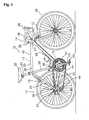
- FIG. 1 a bicycle 10 is illustrated in accordance with a first embodiment of the present invention.
- Figure 1 shows a road bike 10 having a drop-type handlebar unit 14.
- the road bike 10 has a diamond-shaped frame 11 that serves as the framework of the bicycle body.
- the frame 11 has a frame body 12 and a front fork 13.
- the front fork 13 is supported on a front part of the frame 12 such that it can rotate freely about an axis that is tilted slightly from vertical.
- the lower part of the front fork 13 is divided into two prongs.
- the bicycle 10 is also provided with the handlebar unit 14 connected to the front fork 13, and in addition a drive unit or drive train 15, a front wheel 16, a rear wheel 17 and front and rear brake devices 18 and 19.
- the drive train 15 is configured to convert the rider's pedaling force into driving force.
- the front wheel 16 is supported in a freely rotatable manner on the bottom end of the front fork 13 between the prongs.
- the rear wheel 17 is supported in a freely rotatable manner on a rear part of the frame body 12.
- the frame body 12 has a triangular shaped main or front triangle 20 and a rear triangle 21 arranged rearward of the front triangle 20.
- the front triangle 20 is formed by a top tube 25, a down tube 26, head tube 27 and a seat tube 28.
- the top tube 25 is arranged generally horizontally, while the down tube 26 is arranged below the top tube 25 such that it slants upward toward the front.
- the head tube 27 is joined to the front ends of the top tube 25 and the down tube 26, while the seat tube 28 extends diagonally upward and is joined to the rear ends of the top tube 25 and down tube 26.
- a seat post 33 having a saddle 32 fastened thereto is secured in the seat tube 28 in such a manner that its position can be adjusted up and down.
- a cylindrical hanger 29 ( Figure 3) is formed at the portion where the seat tube 28 and the down tube 26 join.
- the rear triangle 21 is formed by a pair of seat stays 30, a pair of chain stays 31 and the seat tube 28.
- the seat stays 30 are joined at their front ends to the seat tube 28 and extend diagonally downward as two separate prongs.
- the chain stays 31 extend rearward as two separate prongs from the bottom end of the seat tube 28
- the handlebar unit 14 includes a handlebar stem 35 that is fastened to the upper part of the front fork 13 in such a manner that its vertical position can be selectively adjusted up and down relative to the front fork 13.
- a handlebar 36 extends to the left and right and is curved at both ends.
- the handlebar 36 is fastened to the top end of the handlebar stem 35.
- a pair of braking devices 38 that are provided with gear shifting capability are mounted to opposite ends of the handlebar 36.
- the drive unit or drive train 15 includes a front crank set or crank unit 41, a rear sprocket assembly or small gear unit 43, a chain 44, a front derailleur 45 and a rear derailleur 46.
- the crank set (crank unit) 41 is mounted on the hanger 29.
- the rear sprocket assembly (small gear unit) 43 mounted in a non-rotatable manner to the free hub or free wheel of the rear wheel 17.
- the chain 44 is arranged on the crank set (gear crank unit) 41 and the rear sprocket assembly (small gear unit) 43 so as to extend therebetween.
- the front derailleur 45 is coupled to the seat tube 28, while the rear derailleur 46 is coupled to the rear triangle 21.
- the derailleur 45 and 46 function as a means of changing gears.
- the front derailleur 45 has a chain guide 45a through which the chain 44 passes.
- the crank set (crank unit) 41 basically includes a crank shaft 50 (Figure 3), a right crank arm (gear crank) 51 and a left crank arm (left crank) 52.
- the crank shaft 50 is supported in a freely rotatable manner in the hanger 29 of the frame 11.
- the right crank arm 51 is crimp-fastened to the right end of the crank shaft 50 and has a pedal 53 (Figure 1) mounted to its tip end, while the left crank arm 52 ( Figure 3) is fastened in a detachable manner to the left end of the crank shaft 50 with another pedal (that is a mirror image of the pedal 53) mounted to its tip end such that the rider can provide a pedaling force to the drive train 15, as best seen in Figure 1.
- crank shaft 50 is mounted in a freely rotatable manner in the hanger 29 by means of a bottom bracket 54 mounted in the hanger 29 for rotation about a central rotation axis X.
- crankset 41 is freely rotatable about the central rotation axis X.
- the crank shaft 50 is a hollow pipe-shaped member made of a high-rigidity alloy, such as chromium-molybdenum steel.
- the radially inwardly facing surface of the left end of crank shaft 50 is provided with internal threads 55b so that the left crank arm 52 can be fastened thereto with a bolt 59.
- the bottom bracket 54 includes a left and right bearing housings 60 and 61, a cylindrical linking member 62, left and right ball bearings 63 and 64, and left and right cover members 65 and 66.
- the left and right bearing housings 60 and 61 are screwed into the ends of the hanger 29.
- the cylindrical linking member 62 is concentric with and connects mates to the left and right bearing housings 60 and 61 via a pair of additional bearings.
- the left and right ball bearings 63 and 64 are mounted in the left and right housings 60 and 61, respectively.
- the left and right cover members 65 and 66 are mounted between the crank shaft 50 and the inner rings (races) of the left and right ball bearings 63 and 64, respectively.
- the ball bearings 63 and 64 are sealed bearings having seals installed between the inner ring (race) and the outer ring (race) and are injected with grease in advance of assembling the bottom bracket 54. Consequently, lubrication maintenance can be eliminated. Arranging the bearings 63 and 64 outside the hanger 29 enables the diameter of the crank shaft 50 to be increased and, as a result, the crank shaft 50 can be made lighter in weight while maintaining high strength and rigidity by making the crank shaft 50 hollow.
- the right crank arm (gear crank) 51 includes a crank connecting part or portion 75, five support arm parts or portions 76 and a main right crank arm part or portion 77.
- the crank connecting portion 75 has an engagement depression 78 that forms a circular space and mounts in a non-rotatable manner to the right end of the crank shaft 50.
- the five support arm portions 76 extend radially outwardly from the crank connecting portion 75 and are configured such that two sprockets 71 and 72 (one large and one small, respectively) can be mounted on the tip ends thereof.
- the main crank arm portion 77 is preferably integrally formed with the crank connecting portion 75 and the five support arm portions 76 such that the right main crank arm portion 77 fixed to the right end of the crank shaft 50.
- the tip ends of the support arm portions 76 are provided with mounting sections (parts) 76a for attaching the sprockets 71 and 72 thereto.
- the mounting sections 76a are recessed on opposite axial sides thereof relative to the other portions to form radially outwardly facing abutment surfaces.
- the sprockets 71 and 72 are mounted on both (opposite) sides of the mounting sections 76a in such a manner that the sprockets 71 and 72 are concentric with respect to the crank shaft 50 and the central rotation axis X.
- each of the mounting sections 76a is provided with a first fastening hole 76b that extends in an axial direction.
- the sprockets 71 and 72 can be fastened simultaneously to the mounting sections 76a with (five) bolts 80 and nuts 81.
- the right main crank portion 77 has a hollow structure and is formed integrally with the crank connecting portion 75 and the support arm portions 76.
- the right crank portion 77 extends radially outwardly, while slanting slightly outward in the axial direction from the outside surface 75a of the crank connecting portion 75.
- a threaded pedal mounting hole 77a is provided in the extended tip end of the right main crank portion 77 for installing the pedal 53.
- the engagement depression 78 of the crank connecting portion 75 is mounted to the second portion 56 of the crank shaft 50.
- the engagement depression 78 is formed to a length (i.e., depth) that is larger than the length of the second portion 56 and reaches almost to the outside surface 75a.
- the outside surface 75a of the crank connecting portion 75 and the main right crank portion 77 is smoothly curved and free of irregularities.
- the depth of the engagement depression 78 is shorter than the diameter of the second portion 56 of the crank shaft 50.
- the sprocket 71 in accordance with a preferred embodiment of the present invention basically includes a sprocket ring part 90, a fastening part 91 and a plurality (five) of tubular members 92.
- the sprocket ring part 90 and the tubular members 92 are constructed of metal (e.g. aluminum alloy), while the fastening part 91 is constructed of synthetic resin, formed integrally with (partially around) the sprocket ring part 90 and the tubular members 92.
- the construction of the sprocket 71 in accordance with the present invention will be explained in more detail below.
- the fastening part 91 is fastened to the right crank arm 51 ( Figures 2 and 3) using the tubular members 92 as also explained in more detail below.
- the sprocket ring part 90 is a ring-shaped member having multiple (i.e. a plurality of) sprocket teeth 90a formed on the outside circumference thereof upon which the chain 44 ( Figure 1) is wrapped. As shown in Figure 6, multiple (i.e. a plurality of) circumferentially spaced through holes 90d are provided that extend between (first and second) lateral sides or side surfaces 90b and 90c of the sprocket ring part 90. Preferably, through holes 90d are arranged around the entire circumference of the sprocket ring part 90. The through holes 90d form a first anchor structure (means) for rigidly connecting the fastening part 91 in a non-rotatable manner.
- first anchor structure means
- the synthetic material of the fastening part 91 extends through the holes 90d to form a second anchor structure that cooperates with the first anchor structure to prevent relative movement therebetween.
- the sprocket ring part 90 is preferably constructed by die punching a metal plate into the ring shape having sprocket teeth 90a formed on the outside circumference thereof and the through holes 90d extending between both lateral faces 90b and 90c thereof.
- the fastening part 91 is preferably constructed of a polyamide-based synthetic resin impregnated with a reinforcing material such as a carbon fiber filler.
- the fastening part 91 is formed integrally around both lateral sides or side surfaces 90b and 90c of the sprocket ring part 90 at an area of the sprocket ring part 90 located radially inward of where the sprocket teeth 90a are formed.
- the fastening part 91 has a ring section (part) 91a and a screw fastening section (part) 91b.
- the ring section 91a is molded integrally (partially) around and through the sprocket ring part 90 (i.e. through the through holes 90d).
- the screw fastening section 91b extends radially inward from the ring section 91a.
- the screw fastening section 91b has a plurality of second fastening holes positioned such that they can be aligned with the first fastening holes 76b.
- the ring section 91 a is formed integrally such that it substantially covers both lateral faces 90b and 90c as well as the radially inwardly facing surface 90e of the sprocket ring part 90.
- the screw fastening section (part) 91b is preferably molded integrally (partially) around the tubular members 92, as explained below.
- the screw fastening section 91b has a plurality (five) of arch elements (parts) 91c that extend radially inwardly from the radially inward facing surface of the ring section 91 a to form a plurality (five) arm fastening flanges (parts) 91d formed on a middle portion of each arch element 91 c.
- the arm fastening flanges 91d are positioned to be aligned face to face with the mounting sections 76a on the tip ends of the support arm portions 76.
- Each fastening flange 91d includes and axially extending (stepped) mounting hole 91e that is arranged to be aligned with one of the first fastening holes 76b.
- the stepped shape of the mounting holes is due to the fastening part 91 being at least partially molded around the tubular members 92.
- the tubular members 92 are mounted to be unmovable relative to the fastening part.
- the tubular members 92 are mounted to be unmovable along the axial direction (i.e. substantially parallel to the central rotation axis X) in the mounting holes 91e.
- the tubular members 92 are preferably constructed of an aluminum (base) alloy. Each tubular member 92 includes a tubular part 92a and a flange section (guard part) 92b extending outwardly from the tubular part 92a relative to a central through axis of the metallic tubular member 92. The flange section 92b is larger than the tubular part 92a.
- the tubular members 92 are preferably identical and preferably attached to the fastening part 91 in and identical manner. Thus, only one of the tubular members 92 will be explained and/or illustrated in detail herein.
- the flange section (guard part) 92b has a first annular axially facing fastener contact surface 92c formed on the outer axial end to receive power (an axial fastening force) from one of the bolts 80 by contacting a head part 80a of one of the bolts 80.
- the outer circumferential part of the flange section 92b is fitted in an inner (annular) circumferential groove of one of the stepped mounting holes 91 e.
- the outer circumferential parts of the flange sections 92b form inner circumferential grooves of the stepped mounting holes 91 e when the fastening part 91 is molded around the outer circumferential parts of the flange sections 92b.
- each of the tubular parts 92a has a second annular axially facing contact surface 92d that contacts one of the mounting sections (parts) 76a of the right crank arm (gear crank) 51 on the outwardly axially facing surface thereof.
- the tubular member 92 and the fastening part 91 are hardly deformed even if a large power affect from a chain is applied, or if the bolt 80 is tightened with too much torque.
- the second contact surface 92d of the metallic tubular member 92 contacts with the mounting section (part) 76a so that the power affects and/or axial tightening forces are applied (i.e. transferred through) the metallic tubular member 92 instead of the synthetic resin fastening part 91 when the sprocket 71 is fixed by the bolts 80. Because of this arrangement, the portions of the fastening part 91 that are fixed with the mounting sections (part) 76a are hardly deformed.
- the bolts 80 are installed from the second fastening hole 91e side and fastened with nuts 81 from the first fastening hole 76b (i.e. the opposite side) side such that the two sprockets 71 and 72 are fixed to opposite faces or sides of the mounting sections 76a.
- the bolts 80 are hollow bolts having enlarged heads with hexagonal sockets and threaded shafts extending therefrom, and the nuts 81 are hollow nuts each having a flange.
- the bolts 80 and nuts 81 are well-known items used for positioning and fastening front sprockets.
- the two sprockets 71 and 72 are fixed on opposite sides of the mounting sections (parts) 76a by the nuts 81 that are mounted from the (inner) side of the sprocket 72 and the bolts 80 that are mounted from the opposite (outer) side of the sprocket 71 (adjacent the flange sections 92b of the tubular members 92 of the sprocket 71).
- the sprocket 71 is manufactured using a process like that shown in Figure 7 in accordance with the present invention. In order to simplify the drawings of Figure 7, only a portion of the ring section 91a and one of the screw fastening sections 91b of the fastening part 91 is shown. The manufacturing process for the sprocket 71 of the present invention will now be discussed in more detail.
- an aluminum (base) alloy plate is die punched to obtain a sprocket ring part 90 shaped as shown in Figures 4 and 6 in a conventional manner.
- an anodic oxide layer e.g. an anodized, oxidized porous aluminum, and/or alumilite layer
- a continuous annular diffusion layer 93a of a fine triazine thiol powder is then formed on both lateral faces 90b and 90c and the inner circumference 90e of the sprocket ring part 90 using an electro deposition method.
- a diffused layer 93b of a fine triazine thiol powder is also formed on the outer circumference surface of the flange section (guard part) 92b and tubular part 92a of the tubular members 92.
- Each of these surface treatments are well known in the metal working/treating arts. Thus, each of these surface treatments will not be discussed and/or illustrated in detail herein, except as related to the present invention.
- the sprocket ring part 90 and the tubular members 92 on which the diffusion layers 93a and 93b have been formed are then inserted into a mold 95 having an upper die 95a and a lower die 95b for molding the fastening part 91.
- the inside of the mold 95 holds the radially outermost area of the sprocket ring part 90 (i.e. the sprocket teeth 90a and the area slightly radially inwardly thereof), while forming a space 95c for forming the fastening part 91 (the ring section 91 a) therearound.
- the inside of the mold 95 holds the inner circumferential area of each tubular member 92 to form a space 95d for forming the fastening part 91 (screw fastening sections 91b) therearound.
- the mold 95 is closed (fastened) and the internal spaces 95c and 95d are filled with a molten polyamide-based synthetic resin that has been impregnated with a reinforcing material such as carbon fiber filler.
- the synthetic resin and the diffusion layers 93a and 93b undergo a chemical reaction such that the fastening part 91 is chemically bonded together with the sprocket ring part 90 and the tubular members.
- the sprocket ring part 90 and the fastening part 91 are fixed together by molding the fastening part 91 integrally (i.e., chemically, adhesively fixing) to both lateral faces 90b and 90c of the sprocket ring part 90, looseness can be prevented and a high rigidity can be maintained between the sprocket ring part 90 and the fastening part 91. Additionally, the manufacturing process can be simplified because it is not necessary to provide a riveting step for installing rivets and/or crimp pins and a crimping step crimping them. Furthermore, the weight of the sprocket can be reduced because the fastening part 91 is made of a synthetic resin.
- the portion of the fastening part 91 that is fixed with the mounting sections (parts) 76a is hardly deformed, lowering of the fixing/fastening power due to deterioration of synthetic resin or deformation can be prevented, and weight saving of the sprocket 71 can be facilitated.
- backlash of the mounting sections (parts) 76a due to deterioration or deformation can be also prevented.
- the sprocket 72 has a ring part 72b with a plurality of sprocket teeth 72a extending outwardly therefrom and a fastening part 72c that is integrally formed with the ring part 72b as a one-piece, unitary member.
- the fastening part 72c projects radially inward from the inner circumference of the ring part 72b.
- the sprocket 72 is constructed of a metallic material (for example, aluminum) using a well-known sprocket design and manufacturing techniques.
- the fastening part 72c of the sprocket 72 and the fastening part 91 of the sprocket 71 are fastened simultaneously to the support arm portions 76.
- the left crank arm 52 has a hollow-structured left main crank arm part or portion 85 provided with a pedal mounting hole 85a for screw-installing a pedal 53 on the tip end thereof.
- the left crank arm 52 is provided with a slit (not shown) in the inner end thereof that mounts to the crank shaft 50.
- the left crank arm 52 is fastened securely to the crank shaft 50 by tightening two mounting bolts 57a and 57b (which are arranged in positions shown below the crank shaft 50 in Figure 3) such that the slit narrowed.
- the two mounting bolts 57a and 57b are, for example, hexagonal socket bolts inserted with their heads facing in opposite directions, respectively.
- the sprockets 71 and 72 are first mounted to the right crank arm 51.
- the sprockets 71 and 72 are 72 are arranged in the recessed areas of the mounting sections 76a such that the respective fastening holes 76b and 91e are aligned face to face with each other.
- the bolts 80 are installed from the sprocket 71 side (i.e., the outside) and the nuts are installed from the sprocket 72 side (i.e., the inside) as best understood from Figures 3 and 5.
- the sprockets 71 and 72 are then secured by turning the bolts 80 using an Allen wrench (key) while preventing the nuts 81 from turning using a special tool.
- the right crank arm 51 is crimp-fastened to the crank shaft 50.
- the right end of the crank shaft 50 is inserted into the engagement depression 78 of the right crank arm 51.
- a crimping tool is mounted from the left end of the crank shaft 50.
- the crank shaft 50 With the crimping tool attached thereto, the crank shaft 50 and are, for example, mounted to a holding tool whose shape is matched to the shape of the outside surface of the crank connecting part 75 and the right crank 77 of the right crank arm 51. Then, the crimping tool is pressed with a pressing device. The right crank arm 51 is thereby crimp-fastened to the crank shaft 50.
Landscapes
- Engineering & Computer Science (AREA)
- Chemical & Material Sciences (AREA)
- Combustion & Propulsion (AREA)
- Transportation (AREA)
- Mechanical Engineering (AREA)
- Gears, Cams (AREA)
- Compositions Of Macromolecular Compounds (AREA)
Abstract
Description
- This application claims priority to Japanese Patent Application No. 2004-183447. The entire disclosure of Japanese Patent Application No. 2004-183447 is hereby incorporated herein by reference.
- The present invention generally relates to a bicycle sprocket. More specifically, the present invention relates to a bicycle sprocket configured to be mounted to a rotational drive unit such as a crank of a bicycle via a synthetic resin fastening part and to have a bicycle (drive-purpose) chain wrapped around the outside circumference of a sprocket ring part thereof.
- A bicycle is generally provided with a drive unit or drive train having front and rear sprockets and a chain wrapped around the sprockets. The front sprocket(s) is provided on the gear crank of the bicycle and the rear sprocket(s) is provided on the free hub of the bicycle. This type of bicycle sprocket is made of such materials as the aluminum having the designation A2014P under the standard JIS H4000 (category) or the iron having the designation SPCC under the standard JIS G3141 (category). When a plurality of sprockets are mounted to the gear crank and free hub in order to provide multiple gears, aluminum is used as the material in order to reduce the weight.
- There are also known bicycle sprocket designs that reduce the weight even further by having a sprocket ring part that is made of aluminum and has the sprocket teeth formed thereon and a fastening part that is made of a carbon fiber material, attached to the inner circumference of the sprocket ring part, and fastened to the gear crank (see German Utility Model Publication No. 20218755). In the case of this sprocket, the fastening part and an inner circumferential portion of the sprocket ring part are fastened together by installing crimp pins in semicircular holes provided in the sprocket ring part and the fastening part. Since the sprocket is made using two separate members, a gap is provided between the sprocket ring part and the fastening part in order to prevent deformation caused by the effects of weather. In addition, mounting holes with steps are formed in the fastening part of the gear crank. In the sprocket constructed in this manner, generally, a bolt (an example of fixed member) is passed through the mounting hole, and the sprocket is fixed to a spider arm of the gear crank via the bolt and the fastening part.
- In the conventional bicycle sprocket just described, age deterioration of synthetic resin fastening part can occur at certain areas resulting in a potential loss of attachment forces. In addition, if the fastening bolts are tightened with too much torque, the synthetic resin fastening part can become deformed, and as the result, there is a possibility for reduced attachment forces. Any reduction in attachment forces can result in play or looseness, adversely affecting operation of the sprocket, shifting of the chain and/or potentially decreasing efficiency of power transfer from the rider to the chain.
- In view of the above, it will be apparent to those skilled in the art from this disclosure that there exists a need for an improved bicycle sprocket. This invention addresses this need in the art as well as other needs, which will become apparent to those skilled in the art from this disclosure.
- One object of the present invention is to provide a bicycle sprocket that is constructed of two different materials, which is light weight, maintains rigidity, prevents looseness or play, and can be fabricated with a simplified manufacturing process.
- Another object of the present invention is to provide a bicycle sprocket that prevents a reduction in attachment forces or the attachment strength because of age deterioration of the synthetic resin fastening part, and/or because of deformation of the synthetic resin fastening part.
- The foregoing objects can basically be attained by providing a bicycle sprocket according to a first aspect of the present invention. The bicycle sprocket according to the first aspect of the present invention includes a sprocket ring part and a synthetic resin fastening part. The sprocket ring part includes an inner periphery and an outer periphery with a plurality of sprocket teeth arranged on the outer periphery. The sprocket ring part extends around a central rotation axis. The synthetic resin fastening part is non-movably coupled to the sprocket ring part at a location radially inwardly of the sprocket teeth relative to the rotation axis. The synthetic resin fastening part includes at least one through hole with a metallic tubular member mounted therein and configured to be fixedly coupled to a rotational drive unit of a bicycle. The metallic tubular member has a first fastener contact surface configured and arranged to receive a fastening force.
- With this sprocket, using the synthetic resin fastening part to connect the sprocket ring part to the turning drive part (a rotational drive unit of a bicycle or crank) results in a sprocket that is relatively light weight. This synthetic resin fastening part has a mounting hole, and the metallic tubular (tubelike) member is mounted in the mounting hole. A fixed member, such as a bolt, is passed through this tubular member to fix the sprocket to the rotational drive unit of the bicycle (turning drive member). With this arrangement, the fastening part and also the first contact surface of the tubular member receive axial fastening forces. Since a metallic tubular member that does not deteriorate with age as much as synthetic resin is mounted in the fastening part, and the first contact surface of the tubular member receives an axial force from the bolt to attach the fixing portion of the fastening part to the rotational drive unit, sufficient attachment forces are maintained, and the fixing portion of the fastening part that is attached to the turning drive member is difficult to be deformed even though relatively soft synthetic resin (i.e. softer than typical metallic materials) is used for the fastening part to achieve weight savings. Because of this arrangement, the reduction of axial fastening forces due to age deterioration of synthetic resin or deformation can be minimized and/or prevented, and thus, weight savings for the sprocket can be facilitated without compromising performance.
- In a bicycle sprocket in accordance with a second aspect of the present invention, the metallic tubular member is non-movable relative to the synthetic resin fastening part in an axial direction substantially parallel to the central rotation axis. In other words, the tubular member is mounted in the mounting hole to become unmovable along the direction of the axis. In this case, since the metallic tubular member is mounted to become unmovable along the direction of the axis, the attachment force from a fixed member such as a bolt can be reliably (certainly) received by the first contact surface.
- In a bicycle sprocket in accordance with a third aspect of the present invention, the synthetic resin fastening part is at least partially integrally molded around the metallic tubular member to prevent movement of the metallic tubular member relative to the synthetic resin fastening part (e.g. especially in the axial direction). In other words, the tubular member is formed with the fastening part. In this case, since the tubular member has the synthetic resin fastening part at least partially molded/formed around it, such as by insert forming, it can be easily mounted to become unmovable along the direction of the axis.
- In a bicycle sprocket in accordance with a fourth aspect of the present invention, the metallic tubular member includes a flange section extending outwardly therefrom relative to a central through axis of the metallic tubular member, the first contact surface being formed on the flange section. In other words, the tubular member has a tubular part and a guard part larger than the tubular part, and the first contact surface is set up on the guard part. In this case, since, by including the guard part, the tubular member can be mounted in the fastening part to become unmovable along the direction of the axis, and the first contact surface can be arranged to contact the fixed member such as a bolt at the relatively larger guard part, the area of the first contact surface gets larger, and the pressure on the first contact surface gets less (per unit area) even if it receives power from the fixed member such as a bolt. In addition, when the fastening part and tubular member are formed together, both parts can be powerfully held (strongly formed) by putting the guard part into the inner member.
- In a bicycle sprocket in accordance with a fifth aspect of the present invention, the metallic tubular member includes a second contact surface that is configured and arranged to contact the rotational drive unit. In other words, the tubular member has the second contact surface that contacts the turning drive member. In this case, since the second contact surface of the metallic tubular member contacts the turning drive member, the axial fastening force (power) is transferred through the tubular member when the sprocket is fixed with the fixed member such as a bolt. Because of this, the fixed portion of the fastening part that is fixed with the turning drive member is hardly deformed.
- In a bicycle sprocket in accordance with a sixth aspect of the present invention, the sprocket ring part includes a pair of sides and the synthetic resin fastening part is at least partially integrally molded around both sides of the sprocket ring part. In other words, the sprocket ring part is metallic, and the fastening part is formed with (i.e. partially around) both sides of the sprocket ring part. In this case, the fastening part is placed on the both sides of the sprocket ring part so that the rigidity between the sprocket ring part and the fastening part can be maintained. In addition, since the crimp pins previously used in the prior art to couple these parts together are unnecessary with the present invention, the manufacturing process can be simplified.
- In a bicycle sprocket in accordance with a seventh aspect of the present invention, the bicycle sprocket further comprises a fastening member with an enlarged head that is sized and configured to contact the first fastener contact surface to apply the fastening force. The fastening member is preferably a bolt with a threaded shaft and the enlarged head arranged at one end of the threaded shaft. In other words, the fixed member is a bolt that has a head, and the tubular member contacts the head of the bolt. In this case, even if the head of the bolt contacts the first contact surface of the tubular member, the first contact surface is hardly deformed.
- In a bicycle sprocket in accordance with an eighth aspect of the present invention, the sprocket ring part includes a first anchor structure and the synthetic resin fastening part includes a second anchor structure that cooperates with the first anchor structure to prevent relative movement therebetween. In other words, the sprocket ring part additionally has an anchoring means to unrotatably connect the fastening part thereto. In this case, the sprocket ring part and the fastening part are unrotatably connected by the anchor means so that rigidity/strength is increased.
- In a bicycle sprocket in accordance with a ninth aspect of the present invention, the synthetic resin fastening part is constructed of a polyamide based-based synthetic resin with a carbon fiber filler impregnated therein. In other words, the fastening part is made of carbon fiber resin incorporation that impregnates a carbon fiber filler with polyamide based synthetic resin. In this case, the strength of the fastening part can be stronger by impregnating carbon fiber than with synthetic resin alone (not including the carbon fiber impregnation).
- In a bicycle sprocket in accordance with a tenth aspect of the present invention, the sprocket ring part is constructed of an aluminum alloy that has an anodic oxide layer formed on the surface thereof. In other words, the sprocket ring part is made of aluminum base alloy that has anodized, oxidized porous aluminum, and/or an alumilite layer formed on its surface. In this case, the corrosion resistence of the sprocket ring part is improved.
- In a bicycle sprocket in accordance with an eleventh aspect of the present invention, the metallic tubular member is constructed of an aluminum alloy. In other words, the tubular member is made of an aluminum base alloy. In this case, even if the tubular member is mounted to prevent deforming of the fastening part, weight savings can be facilitated.
- According to this invention, the metallic tubular member, which is more difficult to be deteriorated with age than synthetic resin, is mounted in the fastening part, and the first contact surface of the tubular member receives power (axial force) from the fixed member such as a bolt. Thus, even if relatively soft synthetic resin (i.e. softer than commonly used metallic materials) is used in the fastening part to facilitate weight saving, adequate fixing forces (power) is maintained, the fixed portion of the fastening part that is fixed to the turning drive member is hardly deformed, and lowering of the fixing forces (power) due to deterioration of synthetic resin and/or deforming can be minimized and/or prevented. Accordingly, weight saving of the sprocket can be facilitated with adversely affecting other characteristics and/or performance of the sprocket.
- These and other objects, features, aspects and advantages of the present invention will become apparent to those skilled in the art from the following detailed description, which, taken in conjunction with the annexed drawings, discloses a preferred embodiment of the present invention.
- Referring now to the attached drawings which form a part of this original disclosure:
- Figure 1 is a side elevational view of bicycle having a front crank set with a sprocket in accordance with a preferred embodiment of the present invention mounted thereto;
- Figure 2 is an enlarged side elevational view of the front crank set of the bicycle illustrated in Figure 1;
- Figure 3 is a partial, transverse, cross sectional view of the front crank set illustrated in Figures 1 and 2, as seen along section line III-III of Figure 2;
- Figure 4 is side elevational view of the large sprocket of the front crank set illustrated in Figures 1-3, with the other parts of the crank set removed for the purpose of illustration;
- Figure 5 is an enlarged, partial cross sectional view of the sprocket illustrated in Figure 4, as seen along section line V-V of Figure 4, with the right crank arm of the crank set coupled thereto for the purpose of illustration;
- Figure 6 is an enlarged partial side elevational view of the sprocket ring part of the sprocket illustrated in Figure 4, in order to illustrate the arrangement of through holes of the sprocket ring part;
- Figure 7 is a diagrammatic view illustrating a manufacturing process for a sprocket in accordance with the present invention;
- Figure 8(a) is an enlarged, partial side elevational view of a sprocket ring part (equivalent to the view of Figure 6) for a modified sprocket in accordance with another preferred embodiment of the present invention;
- Figure 8(b) is a side elevational view of a modified right crank arm with a modified sprocket utilizing the sprocket ring part illustrated in Figure 8(a) in accordance with the present invention; and
- Figure 9 is a diagrammatic view illustrating part of a modified manufacturing process in accordance with the present invention.
-
- Selected embodiments of the present invention will now be explained with reference to the drawings. It will be apparent to those skilled in the art from this disclosure that the following descriptions of the embodiments of the present invention are provided for illustration only and not for the purpose of limiting the invention as defined by the appended claims and their equivalents.
- Referring initially to Figure 1, a
bicycle 10 is illustrated in accordance with a first embodiment of the present invention. As an example of abicycle 10 that employs an embodiment of the present invention, Figure 1 shows aroad bike 10 having a drop-type handlebar unit 14. Theroad bike 10 has a diamond-shapedframe 11 that serves as the framework of the bicycle body. Theframe 11 has aframe body 12 and afront fork 13. Thefront fork 13 is supported on a front part of theframe 12 such that it can rotate freely about an axis that is tilted slightly from vertical. The lower part of thefront fork 13 is divided into two prongs. Thebicycle 10 is also provided with thehandlebar unit 14 connected to thefront fork 13, and in addition a drive unit or drivetrain 15, afront wheel 16, arear wheel 17 and front andrear brake devices 18 and 19. Thedrive train 15 is configured to convert the rider's pedaling force into driving force. Thefront wheel 16 is supported in a freely rotatable manner on the bottom end of thefront fork 13 between the prongs. Therear wheel 17 is supported in a freely rotatable manner on a rear part of theframe body 12. - The
frame body 12 has a triangular shaped main orfront triangle 20 and arear triangle 21 arranged rearward of thefront triangle 20. Thefront triangle 20 is formed by atop tube 25, adown tube 26,head tube 27 and aseat tube 28. Thetop tube 25 is arranged generally horizontally, while thedown tube 26 is arranged below thetop tube 25 such that it slants upward toward the front. Thehead tube 27 is joined to the front ends of thetop tube 25 and thedown tube 26, while theseat tube 28 extends diagonally upward and is joined to the rear ends of thetop tube 25 and downtube 26. Aseat post 33 having asaddle 32 fastened thereto is secured in theseat tube 28 in such a manner that its position can be adjusted up and down. A cylindrical hanger 29 (Figure 3) is formed at the portion where theseat tube 28 and thedown tube 26 join. Therear triangle 21 is formed by a pair of seat stays 30, a pair of chain stays 31 and theseat tube 28. The seat stays 30 are joined at their front ends to theseat tube 28 and extend diagonally downward as two separate prongs. The chain stays 31 extend rearward as two separate prongs from the bottom end of theseat tube 28 - The
handlebar unit 14 includes ahandlebar stem 35 that is fastened to the upper part of thefront fork 13 in such a manner that its vertical position can be selectively adjusted up and down relative to thefront fork 13. Ahandlebar 36 extends to the left and right and is curved at both ends. Thehandlebar 36 is fastened to the top end of thehandlebar stem 35. A pair ofbraking devices 38 that are provided with gear shifting capability are mounted to opposite ends of thehandlebar 36. - The drive unit or drive
train 15 includes a front crank set or crankunit 41, a rear sprocket assembly orsmall gear unit 43, achain 44, afront derailleur 45 and arear derailleur 46. The crank set (crank unit) 41 is mounted on thehanger 29. The rear sprocket assembly (small gear unit) 43 mounted in a non-rotatable manner to the free hub or free wheel of therear wheel 17. Thechain 44 is arranged on the crank set (gear crank unit) 41 and the rear sprocket assembly (small gear unit) 43 so as to extend therebetween. Thefront derailleur 45 is coupled to theseat tube 28, while therear derailleur 46 is coupled to therear triangle 21. Thederailleurs front derailleur 45 has a chain guide 45a through which thechain 44 passes. - As shown in Figures 1-3, the crank set (crank unit) 41 basically includes a crank shaft 50 (Figure 3), a right crank arm (gear crank) 51 and a left crank arm (left crank) 52. The
crank shaft 50 is supported in a freely rotatable manner in thehanger 29 of theframe 11. Theright crank arm 51 is crimp-fastened to the right end of thecrank shaft 50 and has a pedal 53 (Figure 1) mounted to its tip end, while the left crank arm 52 (Figure 3) is fastened in a detachable manner to the left end of thecrank shaft 50 with another pedal (that is a mirror image of the pedal 53) mounted to its tip end such that the rider can provide a pedaling force to thedrive train 15, as best seen in Figure 1. - As shown in Figure 3, the
crank shaft 50 is mounted in a freely rotatable manner in thehanger 29 by means of abottom bracket 54 mounted in thehanger 29 for rotation about a central rotation axis X. Thus, thecrankset 41 is freely rotatable about the central rotation axis X. Thecrank shaft 50 is a hollow pipe-shaped member made of a high-rigidity alloy, such as chromium-molybdenum steel. The radially inwardly facing surface of the left end ofcrank shaft 50 is provided withinternal threads 55b so that theleft crank arm 52 can be fastened thereto with abolt 59. - The
bottom bracket 54 includes a left andright bearing housings cylindrical linking member 62, left andright ball bearings right cover members right bearing housings hanger 29. Thecylindrical linking member 62 is concentric with and connects mates to the left andright bearing housings right ball bearings right housings right cover members crank shaft 50 and the inner rings (races) of the left andright ball bearings - The
ball bearings bottom bracket 54. Consequently, lubrication maintenance can be eliminated. Arranging thebearings hanger 29 enables the diameter of thecrank shaft 50 to be increased and, as a result, thecrank shaft 50 can be made lighter in weight while maintaining high strength and rigidity by making the crankshaft 50 hollow. - As shown in Figures 2 and 3, the right crank arm (gear crank) 51 includes a crank connecting part or
portion 75, five support arm parts orportions 76 and a main right crank arm part orportion 77. Thecrank connecting portion 75 has anengagement depression 78 that forms a circular space and mounts in a non-rotatable manner to the right end of thecrank shaft 50. The fivesupport arm portions 76 extend radially outwardly from thecrank connecting portion 75 and are configured such that twosprockets 71 and 72 (one large and one small, respectively) can be mounted on the tip ends thereof. The maincrank arm portion 77 is preferably integrally formed with thecrank connecting portion 75 and the fivesupport arm portions 76 such that the right main crankarm portion 77 fixed to the right end of thecrank shaft 50. - The tip ends of the
support arm portions 76 are provided with mounting sections (parts) 76a for attaching thesprockets sections 76a are recessed on opposite axial sides thereof relative to the other portions to form radially outwardly facing abutment surfaces. Thus, thesprockets sections 76a in such a manner that thesprockets crank shaft 50 and the central rotation axis X. As shown in Figure 5, each of the mountingsections 76a is provided with afirst fastening hole 76b that extends in an axial direction. Thus, thesprockets sections 76a with (five)bolts 80 and nuts 81. As shown in Figure 3, the right main crankportion 77 has a hollow structure and is formed integrally with thecrank connecting portion 75 and thesupport arm portions 76. Theright crank portion 77 extends radially outwardly, while slanting slightly outward in the axial direction from the outside surface 75a of thecrank connecting portion 75. A threadedpedal mounting hole 77a is provided in the extended tip end of the right main crankportion 77 for installing thepedal 53. - As shown in Figure 3, the
engagement depression 78 of thecrank connecting portion 75 is mounted to thesecond portion 56 of thecrank shaft 50. Theengagement depression 78 is formed to a length (i.e., depth) that is larger than the length of thesecond portion 56 and reaches almost to the outside surface 75a. As a result, the outside surface 75a of thecrank connecting portion 75 and the main right crankportion 77 is smoothly curved and free of irregularities. Also, the depth of theengagement depression 78 is shorter than the diameter of thesecond portion 56 of thecrank shaft 50. - As shown in Figures 4-6, the
sprocket 71 in accordance with a preferred embodiment of the present invention basically includes asprocket ring part 90, afastening part 91 and a plurality (five) oftubular members 92. Thesprocket ring part 90 and thetubular members 92 are constructed of metal (e.g. aluminum alloy), while thefastening part 91 is constructed of synthetic resin, formed integrally with (partially around) thesprocket ring part 90 and thetubular members 92. The construction of thesprocket 71 in accordance with the present invention will be explained in more detail below. Thefastening part 91 is fastened to the right crank arm 51 (Figures 2 and 3) using thetubular members 92 as also explained in more detail below. - The
sprocket ring part 90 is a ring-shaped member having multiple (i.e. a plurality of)sprocket teeth 90a formed on the outside circumference thereof upon which the chain 44 (Figure 1) is wrapped. As shown in Figure 6, multiple (i.e. a plurality of) circumferentially spaced throughholes 90d are provided that extend between (first and second) lateral sides or side surfaces 90b and 90c of thesprocket ring part 90. Preferably, throughholes 90d are arranged around the entire circumference of thesprocket ring part 90. The throughholes 90d form a first anchor structure (means) for rigidly connecting thefastening part 91 in a non-rotatable manner. The synthetic material of thefastening part 91 extends through theholes 90d to form a second anchor structure that cooperates with the first anchor structure to prevent relative movement therebetween. In this embodiment, thesprocket ring part 90 is preferably constructed by die punching a metal plate into the ring shape havingsprocket teeth 90a formed on the outside circumference thereof and the throughholes 90d extending between both lateral faces 90b and 90c thereof. - The
fastening part 91 is preferably constructed of a polyamide-based synthetic resin impregnated with a reinforcing material such as a carbon fiber filler. Thefastening part 91 is formed integrally around both lateral sides or side surfaces 90b and 90c of thesprocket ring part 90 at an area of thesprocket ring part 90 located radially inward of where thesprocket teeth 90a are formed. Thefastening part 91 has a ring section (part) 91a and a screw fastening section (part) 91b. Thering section 91a is molded integrally (partially) around and through the sprocket ring part 90 (i.e. through the throughholes 90d). Thescrew fastening section 91b extends radially inward from thering section 91a. Thescrew fastening section 91b has a plurality of second fastening holes positioned such that they can be aligned with thefirst fastening holes 76b. Thering section 91 a is formed integrally such that it substantially covers both lateral faces 90b and 90c as well as the radially inwardly facingsurface 90e of thesprocket ring part 90. The screw fastening section (part) 91b is preferably molded integrally (partially) around thetubular members 92, as explained below. Thescrew fastening section 91b has a plurality (five) of arch elements (parts) 91c that extend radially inwardly from the radially inward facing surface of thering section 91 a to form a plurality (five) arm fastening flanges (parts) 91d formed on a middle portion of eacharch element 91 c. Thearm fastening flanges 91d are positioned to be aligned face to face with the mountingsections 76a on the tip ends of thesupport arm portions 76. Eachfastening flange 91d includes and axially extending (stepped) mountinghole 91e that is arranged to be aligned with one of thefirst fastening holes 76b. The stepped shape of the mounting holes is due to thefastening part 91 being at least partially molded around thetubular members 92. Thus, thetubular members 92 are mounted to be unmovable relative to the fastening part. In any case, thetubular members 92 are mounted to be unmovable along the axial direction (i.e. substantially parallel to the central rotation axis X) in the mountingholes 91e. - The
tubular members 92 are preferably constructed of an aluminum (base) alloy. Eachtubular member 92 includes atubular part 92a and a flange section (guard part) 92b extending outwardly from thetubular part 92a relative to a central through axis of the metallictubular member 92. Theflange section 92b is larger than thetubular part 92a. Thetubular members 92 are preferably identical and preferably attached to thefastening part 91 in and identical manner. Thus, only one of thetubular members 92 will be explained and/or illustrated in detail herein. The flange section (guard part) 92b has a first annular axially facingfastener contact surface 92c formed on the outer axial end to receive power (an axial fastening force) from one of thebolts 80 by contacting ahead part 80a of one of thebolts 80. The outer circumferential part of theflange section 92b is fitted in an inner (annular) circumferential groove of one of the stepped mountingholes 91 e. In fact, the outer circumferential parts of theflange sections 92b form inner circumferential grooves of the stepped mountingholes 91 e when thefastening part 91 is molded around the outer circumferential parts of theflange sections 92b. Because of this, thetubular members 92 are retained with the fastening part 91 (i.e. thetubular members 92 will not fall out of theholes 91e and can be certainly fixed to be unmovable along the direction of the axis X). In addition, each of thetubular parts 92a has a second annular axially facingcontact surface 92d that contacts one of the mounting sections (parts) 76a of the right crank arm (gear crank) 51 on the outwardly axially facing surface thereof. Since thefirst contact surface 92c of the metallictubular member 92 contacts with thehead 80a of thebolt 80 rather than thefastening part 91 in this manner, thetubular member 92 and thefastening part 91 are hardly deformed even if a large power affect from a chain is applied, or if thebolt 80 is tightened with too much torque. In addition, thesecond contact surface 92d of the metallictubular member 92 contacts with the mounting section (part) 76a so that the power affects and/or axial tightening forces are applied (i.e. transferred through) the metallictubular member 92 instead of the syntheticresin fastening part 91 when thesprocket 71 is fixed by thebolts 80. Because of this arrangement, the portions of thefastening part 91 that are fixed with the mounting sections (part) 76a are hardly deformed. - The
bolts 80 are installed from thesecond fastening hole 91e side and fastened withnuts 81 from thefirst fastening hole 76b (i.e. the opposite side) side such that the twosprockets sections 76a. Thebolts 80 are hollow bolts having enlarged heads with hexagonal sockets and threaded shafts extending therefrom, and the nuts 81 are hollow nuts each having a flange. Thebolts 80 andnuts 81 are well-known items used for positioning and fastening front sprockets. In other words, the twosprockets sprocket 72 and thebolts 80 that are mounted from the opposite (outer) side of the sprocket 71 (adjacent theflange sections 92b of thetubular members 92 of the sprocket 71). - The
sprocket 71 is manufactured using a process like that shown in Figure 7 in accordance with the present invention. In order to simplify the drawings of Figure 7, only a portion of thering section 91a and one of thescrew fastening sections 91b of thefastening part 91 is shown. The manufacturing process for thesprocket 71 of the present invention will now be discussed in more detail. - First, an aluminum (base) alloy plate is die punched to obtain a
sprocket ring part 90 shaped as shown in Figures 4 and 6 in a conventional manner. Preferably, an anodic oxide layer (e.g. an anodized, oxidized porous aluminum, and/or alumilite layer) is then formed on the surface of thesprocket ring part 90. A continuous annular diffusion layer 93a of a fine triazine thiol powder is then formed on both lateral faces 90b and 90c and theinner circumference 90e of thesprocket ring part 90 using an electro deposition method. In addition, a diffusedlayer 93b of a fine triazine thiol powder is also formed on the outer circumference surface of the flange section (guard part) 92b andtubular part 92a of thetubular members 92. Each of these surface treatments are well known in the metal working/treating arts. Thus, each of these surface treatments will not be discussed and/or illustrated in detail herein, except as related to the present invention. Thesprocket ring part 90 and thetubular members 92 on which the diffusion layers 93a and 93b have been formed are then inserted into amold 95 having anupper die 95a and alower die 95b for molding thefastening part 91. The inside of themold 95 holds the radially outermost area of the sprocket ring part 90 (i.e. thesprocket teeth 90a and the area slightly radially inwardly thereof), while forming aspace 95c for forming the fastening part 91 (thering section 91 a) therearound. Similarly, the inside of themold 95 holds the inner circumferential area of eachtubular member 92 to form aspace 95d for forming the fastening part 91 (screwfastening sections 91b) therearound. After thesprocket ring part 90 and thetubular members 92 are positioned, themold 95 is closed (fastened) and theinternal spaces fastening part 91 is chemically bonded together with thesprocket ring part 90 and the tubular members. Thus, by using an insert molding technique in this manner, asprocket 71 having afastening part 91 that is molded integrally with thesprocket ring part 90 and thetubular members 92 is completed. - Since the
sprocket ring part 90 and thefastening part 91 are fixed together by molding thefastening part 91 integrally (i.e., chemically, adhesively fixing) to both lateral faces 90b and 90c of thesprocket ring part 90, looseness can be prevented and a high rigidity can be maintained between thesprocket ring part 90 and thefastening part 91. Additionally, the manufacturing process can be simplified because it is not necessary to provide a riveting step for installing rivets and/or crimp pins and a crimping step crimping them. Furthermore, the weight of the sprocket can be reduced because thefastening part 91 is made of a synthetic resin. - Similar advantages are obtained with the connection between the
fastening part 91 and thetubular members 92. Moreover, since the metallictubular members 92 that are more difficult to deteriorate due to age than synthetic resin are mounted in thefastening part 91, and the first contact surfaces 92c of thetubular members 92 receive power (axial fastening forces) from thebolts 80, even if relatively softer synthetic resin than typical metallic materials is used in thefastening part 91 to facilitate weight saving, enough fastening power/force is maintained. Thus, the portion of thefastening part 91 that is fixed with the mounting sections (parts) 76a is hardly deformed, lowering of the fixing/fastening power due to deterioration of synthetic resin or deformation can be prevented, and weight saving of thesprocket 71 can be facilitated. In addition, backlash of the mounting sections (parts) 76a due to deterioration or deformation can be also prevented. - The
sprocket 72 has aring part 72b with a plurality of sprocket teeth 72a extending outwardly therefrom and afastening part 72c that is integrally formed with thering part 72b as a one-piece, unitary member. Thefastening part 72c projects radially inward from the inner circumference of thering part 72b. Thesprocket 72 is constructed of a metallic material (for example, aluminum) using a well-known sprocket design and manufacturing techniques. Thefastening part 72c of thesprocket 72 and thefastening part 91 of thesprocket 71 are fastened simultaneously to thesupport arm portions 76. - As shown in Figure 3, the left crank
arm 52 has a hollow-structured left main crank arm part orportion 85 provided with apedal mounting hole 85a for screw-installing a pedal 53 on the tip end thereof. Theleft crank arm 52 is provided with a slit (not shown) in the inner end thereof that mounts to thecrank shaft 50. Theleft crank arm 52 is fastened securely to thecrank shaft 50 by tightening two mountingbolts crank shaft 50 in Figure 3) such that the slit narrowed. The two mountingbolts - When mounting the crank set (crank unit) 41 configured as disclosed herein is mounted to the
bottom bracket 54, thesprockets right crank arm 51. When thesprockets right crank arm 51, thesprockets 71 are 72 are arranged in the recessed areas of the mountingsections 76a such that therespective fastening holes bolts 80 are installed from thesprocket 71 side (i.e., the outside) and the nuts are installed from thesprocket 72 side (i.e., the inside) as best understood from Figures 3 and 5. Thesprockets bolts 80 using an Allen wrench (key) while preventing the nuts 81 from turning using a special tool. - After the
sprockets right crank arm 51 is crimp-fastened to thecrank shaft 50. In order to perform crimp-fastening, the right end of thecrank shaft 50 is inserted into theengagement depression 78 of theright crank arm 51. Then, a crimping tool is mounted from the left end of thecrank shaft 50. With the crimping tool attached thereto, thecrank shaft 50 and are, for example, mounted to a holding tool whose shape is matched to the shape of the outside surface of thecrank connecting part 75 and the right crank 77 of theright crank arm 51. Then, the crimping tool is pressed with a pressing device. Theright crank arm 51 is thereby crimp-fastened to thecrank shaft 50. -
- (a) Referring to Figures 8(a) and 8(b), another embodiment of the present invention
will now be discussed in more detail. In the previous embodiment the anchor structure
(means) of the
sprocket ring part 90 comprised multiple circumferentially-spaced throughholes 90d provided in the lateral faces 90b (as shown in Figure 6). However, it is also acceptable to replace thesprocket ring part 90 with a modified sprocket ring part 90' that has a modified anchor structure (means) at the inner circumference thereof that includes multiple protrusions anddepressions 90f that are circumferentially arranged on the radially inward facingsurface 90e' of the sprocket ring part 90' (as shown in Figure 8(a)). In other words, the sprocket ring part of the present invention can have the configuration shown in Figure 6 and/or the configuration shown in Figure 8(a) about its entire inner circumference. The modified sprocket ring part 90' is identical to thesprocket ring part 90, except the sprocket ring part 90' is preferably provided with the multiple protrusions anddepressions 90f (Figure 8(a)) instead of theholes 90d (Figure 6), as mentioned above. Thus, the sprocket ring part 90' will not be discussed and/or illustrated in detail herein. Rather, it will be apparent to those skilled in the art from this disclosure that the descriptions and illustrations of thesprocket ring part 90 also apply to the modified sprocket ring part 90', except as explained and illustrated herein. Moreover, it will be apparent to those skilled in the art from this disclosure that the sprocket ring part 90' is configured to be used in place of thesprocket ring part 90 to form a modified sprocket 71' of a modified right crank arm 51', as seen in Figure 8(b). In view of the similarities between thesprocket ring parts 90 and 90' identical reference numerals will be used to identify identical parts, while identical reference numerals with a prime (') will be used to identify modified parts of the sprocket ring part 90'. The right crank arm 51' and the sprocket 71' are identical to theright crank arm 51 and thesprocket 71 of the previous embodiment, except for the use of the modified sprocket ring part 90'. In any case, it will be apparent to those skilled in the art from this disclosure that the sprocket ring part of the present invention preferably includes an anchor structure (means) to facilitate a tight connection with thefastening part 91. - (b) Although the previous embodiments described examples of sprockets for a road bike, the present invention can be applied to any bicycle.
- (c) Although the previous embodiments described examples of a sprockets
configured to be mounted to a crank unit (crank set) 41 whose right crank arm 51 (51') is
crimp-fastened to the
crank shaft 50 that has the form of a hollow cylinder over its entire length, the present invention can also be applied to a sprocket configured to be mounted to a crank unit whose gear crank is bolt-fastened to the crank shaft or a crank unit having a separate right crank that is bolt-fastened to the crank shaft together with the gear crank. The present invention can also be applied to a sprocket configured to be mounted to the small (rear sprocket assembly)gear unit 43. Furthermore, it is acceptable for thesprocket 72, to also include a sprocket ring part made of an aluminum alloy and a fastening part made of a synthetic resin. In other words, while the features of the sprockets 71 (71') and the manufacturing techniques utilized to make the sprockets 71 (71') are particularly useful for the largest sprocket because it is typically heavier than smaller sprockets, it will be apparent to those skilled in the art from this disclosure that the present invention can be applied to any sized sprocket where the advantages of the present invention are desirable. - (d) Although in the previous embodiments the sprocket ring part 90 (90') is
constructed of aluminum and the
fastening part 91 is constructed of a polyamide-based synthetic resin, it will be apparent to those skilled in the art from this disclosure that it is acceptable for the sprocket ring part 90 (90') to be made of any other lightweight metallic material and for thefastening part 91 to be made of any other lightweight synthetic resin as needed and/or desired. - (e) Although in the previous embodiments the sprocket ring part 90 (90') is made by
die punching an aluminum plate (metal plate) into the desired shape with the desired anchor
structure (means), it will be apparent to those skilled in the art from this disclosure that it is
also acceptable to fabricate the sprocket ring part 90 (90') as shown in Figure 9 by die
punching a
metal plate 96 into a flat rope-like piece having thesprocket teeth 90a arranged lengthwise on one side thereof and the anchor structure (means) along the opposite side, and then bending the rope-like piece into a ring shape in such a manner that thesprocket teeth 90a face radially outward and the anchor structure (means) is arranged radially inwardly. In such a case, agap 90g is formed in the sprocket ring part 90 (90'). It is acceptable to either join thegap 90g by welding or crimping or to leave the gap unjoined. Even if thegap 90g is left unjoined, it is unlikely that the gap will cause a problem because the sprocket ring part 90 (90') is fixed to thefastening part 91 by the integral molding of thefastening part 91 described above. - (f) In the previous embodiments, each
tubular member 92 is configured as a tube with an annular flange section (guard part) 92b. However, it will be apparent to those skilled in the art from this disclosure that the tubular members may be constructed (configured) without annular flange sections (guard parts). - (g) In the previous embodiments, the
sprocket ring part 90 and thefastening part 91 are formed together by molding the fastening part partially around thesprocket ring part 90. However, it will be apparent to those skilled in the art from this disclosure that thesprocket ring part 90 may be fixed to thefastening part 91 by alternative fixing methods, such as with crimp pins or threaded fasteners (e.g. a screw clamp arrangement or a bolt and nut clamping arrangement). In addition, it will be apparent to those skilled in the art from this disclosure that thetubular members 92 as well, may be fixed to thefastening part 91 by alternative fixing methods, such as with a retaining ring or threaded fasteners (e.g. a screw clamp arrangement or a bolt and nut clamping arrangement). -
- As used herein to describe the present invention, the following directional terms "forward, rearward, above, downward, vertical, horizontal, below and transverse" as well as any other similar directional terms refer to those directions of a bicycle equipped with the present invention. Accordingly, these terms, as utilized to describe the present invention should be interpreted relative to a bicycle equipped with the present invention.
- In understanding the scope of the present invention, the term "comprising" and its derivatives, as used herein, are intended to be open ended terms that specify the presence of the stated features, elements, components, groups, integers, and/or steps, but do not exclude the presence of other unstated features, elements, components, groups, integers and/or steps. The foregoing also applies to words having similar meanings such as the terms, "including", "having" and their derivatives. Also, the terms "member" or "element" when used in the singular can have the dual meaning of a single part or a plurality of parts. Finally, terms of degree such as "substantially", "about" and "approximately" as used herein mean a reasonable amount of deviation of the modified term such that the end result is not significantly changed. These terms of degree should be construed as including a deviation of at least ± 5% of the modified term if this deviation would not negate the meaning of the word it modifies.
- While only selected embodiments have been chosen to illustrate the present invention, it will be apparent to those skilled in the art from this disclosure that various changes and modifications can be made herein without departing from the scope of the invention as defined in the appended claims. Furthermore, the foregoing descriptions of the embodiments according to the present invention are provided for illustration only, and not for the purpose of limiting the invention as defined by the appended claims and their equivalents.
Claims (13)
- A bicycle sprocket comprising:a sprocket ring part (72, 90, 90') including an inner periphery and an outer periphery with a plurality of sprocket teeth (72a, 90a) arranged on the outer periphery, the sprocket ring part (72, 90, 90') extending around a central rotation axis (X); anda synthetic resin fastening part (72c, 91) non-movably coupled to the sprocket ring part (72, 90, 90') at a location radially inwardly of the sprocket teeth (72a, 90a) relative to the rotation axis (X), the synthetic resin fastening part (72c, 91) including at least one through hole with a metallic tubular member (92) mounted therein and configured to be fixedly coupled to a rotational drive unit of a bicycle (10), the metallic tubular member (92) having a first fastener contact surface (92c) configured and arranged to receive a fastening force.
- The bicycle sprocket as recited in claim 1, wherein
the metallic tubular member (92) is non-movable relative to the synthetic resin fastening part (72c, 91) in an axial direction substantially parallel to the central rotation axis (X). - The bicycle sprocket as recited in claim 1 or 2, wherein
the synthetic resin fastening part (72c, 91) is at least partially integrally molded around the metallic tubular member (92) to prevent movement of the metallic tubular member (92) relative to the synthetic resin fastening part (72c, 91) in an axial direction substantially parallel to the central rotation axis (X). - The bicycle sprocket as recited in any of the preceding claims, wherein
the metallic tubular member (92) includes a flange section (92b) extending outwardly therefrom relative to a central through axis of the metallic tubular member (92), the first contact surface (92c) being formed on the flange section (92b). - The bicycle sprocket as recited in any of the preceding claims, wherein
the metallic tubular member (92) includes a second contact surface (92d) that is configured and arranged to contact the rotational drive unit. - The bicycle sprocket as recited in any of the preceding claims, wherein
the sprocket ring part (72, 90, 90') includes a pair of sides and the synthetic resin fastening part (72c, 91) is at least partially integrally molded around both sides of the sprocket ring part (72, 90, 90'). - The bicycle sprocket as recited in any of the preceding claims, further comprising
a fastening member with an enlarged head that is sized and configured to contact the first fastener contact surface (92c) to apply the fastening force. - The bicycle sprocket as recited in claim 7, wherein
the fastening member is a bolt (80) with a threaded shaft and the enlarged head (80a) arranged at one end of the threaded shaft. - The bicycle sprocket as recited in any of the preceding claims, wherein
the sprocket ring part (72, 90, 90') includes a first anchor structure and the synthetic resin fastening part (72c, 91) includes a second anchor structure that cooperates with the first anchor structure to prevent relative movement therebetween. - The bicycle sprocket as recited in any of the preceding claims, wherein
the synthetic resin fastening part (72c, 91) is constructed of a polyamide based-based synthetic resin with a carbon fiber filler impregnated therein. - The bicycle sprocket as recited in any of the preceding claims, wherein
the sprocket ring part (72, 90, 90') is constructed of an aluminum alloy that has an anodic oxide layer formed on the surface thereof. - The bicycle sprocket as recited in any of the preceding claims, wherein
the metallic tubular member (92) is constructed of an aluminum alloy. - The bicycle sprocket as recited in any of claims 2 to 12, wherein
the synthetic resin fastening part (72c, 91) is at least partially integrally molded around the metallic tubular member (92) to prevent movement of the metallic tubular member (92) relative to the synthetic resin fastening part (72c, 91) in the axial direction.
Applications Claiming Priority (2)
| Application Number | Priority Date | Filing Date | Title |
|---|---|---|---|
| JP2004183447 | 2004-06-22 | ||
| JP2004183447A JP2006007799A (en) | 2004-06-22 | 2004-06-22 | Sprocket for bicycle |
Publications (3)
| Publication Number | Publication Date |
|---|---|
| EP1609714A2 true EP1609714A2 (en) | 2005-12-28 |
| EP1609714A3 EP1609714A3 (en) | 2007-07-18 |
| EP1609714B1 EP1609714B1 (en) | 2009-12-09 |
Family
ID=34937349
Family Applications (1)
| Application Number | Title | Priority Date | Filing Date |
|---|---|---|---|
| EP05012459A Revoked EP1609714B1 (en) | 2004-06-22 | 2005-06-09 | Bicycle sprocket |
Country Status (6)
| Country | Link |
|---|---|
| US (1) | US7850564B2 (en) |
| EP (1) | EP1609714B1 (en) |
| JP (1) | JP2006007799A (en) |
| CN (1) | CN100548788C (en) |
| DE (1) | DE602005018131D1 (en) |
| TW (1) | TWI254689B (en) |
Cited By (8)
| Publication number | Priority date | Publication date | Assignee | Title |
|---|---|---|---|---|
| DE102006022343A1 (en) * | 2006-05-12 | 2007-11-15 | Shimano Inc., Sakai | Multicomponent gear |
| EP1884461A3 (en) * | 2006-08-03 | 2010-11-17 | CAMPAGNOLO S.r.l. | Right crank arm assembly for a bicycle and crank arm thereof |
| EP2578486A1 (en) * | 2011-10-05 | 2013-04-10 | Shimano Inc. | Bicycle crank assembly |
| US8479610B2 (en) | 2006-08-03 | 2013-07-09 | Campagnolo S.R.L. | Right crank arm assembly for a bicycle and crank arm and front sprocket |
| DE202013011442U1 (en) | 2013-12-20 | 2014-01-23 | Sram Deutschland Gmbh | Sprocket |
| DE102006062877B4 (en) * | 2006-05-12 | 2015-12-10 | Shimano Inc. | Multicomponent gear |
| US9821366B2 (en) | 2014-06-01 | 2017-11-21 | Shimano Inc. | Disc brake rotor and method of manufacturing disc brake rotor |
| EP2065297B1 (en) | 2007-11-27 | 2019-04-03 | Shimano Inc. | Bicycle rear derailleur |
Families Citing this family (60)
| Publication number | Priority date | Publication date | Assignee | Title |
|---|---|---|---|---|
| EP1486412B1 (en) | 2003-06-10 | 2014-05-07 | Campagnolo S.R.L. | Bicycle pedal crank |
| EP2110302A1 (en) | 2003-06-11 | 2009-10-21 | CAMPAGNOLO S.r.l. | Bicycle component |
| JP2005053410A (en) * | 2003-08-07 | 2005-03-03 | Shimano Inc | Sprocket for bicycle |
| JP2006248290A (en) * | 2005-03-09 | 2006-09-21 | Shimano Inc | Sprocket for bicycle |
| EP1818252B1 (en) | 2006-02-14 | 2011-09-07 | CAMPAGNOLO S.r.l. | Bicycle pedal crank and method for manufactoring such a pedal crank |
| WO2008058164A2 (en) | 2006-11-06 | 2008-05-15 | Quarq Technology, Inc. | Crankset based bicycle power measurement |
| US20080161145A1 (en) * | 2006-12-28 | 2008-07-03 | Shimano Inc. | Bicycle chain wheel with fastener cover |
| US20080161146A1 (en) * | 2006-12-28 | 2008-07-03 | Shimano Inc. | Bicycle chain wheel with fastener covers |
| US20080312016A1 (en) * | 2007-06-13 | 2008-12-18 | Douglas Chiang | Light weight Chain Wheel Having Concrete Structure |
| ITMI20071661A1 (en) | 2007-08-09 | 2009-02-10 | Campagnolo Srl | ASSEEME OF WHEELS TOOTHED FOR A BICYCLE |
| US8006574B2 (en) * | 2007-11-06 | 2011-08-30 | Sram, Llc | Crankset based bicycle power measurement |
| US8550944B2 (en) * | 2008-10-01 | 2013-10-08 | Sram, Llc | Multi-speed sprocket assembly |
| US8820192B2 (en) | 2009-04-29 | 2014-09-02 | Race Face Prerformance Products Inc. | Bicycle crank arm and insert therefore |
| WO2011157415A1 (en) * | 2010-06-15 | 2011-12-22 | Mxc Gmbh | Sprocket |
| DE102011013695B4 (en) * | 2011-03-11 | 2024-02-01 | Sram Deutschland Gmbh | Drive unit on the rear wheel of a bicycle |
| US20130116074A1 (en) * | 2011-11-08 | 2013-05-09 | Chang Hui Lin | Sprocket wheel for bicycle |
| US9182027B2 (en) | 2011-12-06 | 2015-11-10 | Sram, Llc | Chainring |
| CN103419893A (en) * | 2012-05-18 | 2013-12-04 | 株式会社岛野 | Sprocket for bike |
| US10315724B2 (en) | 2013-01-11 | 2019-06-11 | Shimano Inc. | Composite bicycle component |
| US9555855B2 (en) * | 2013-05-07 | 2017-01-31 | Shimano Inc. | Bicycle sprocket |
| JP6203540B2 (en) * | 2013-05-29 | 2017-09-27 | ブリヂストンサイクル株式会社 | Bicycle toothed pulley assembly |
| US9581229B2 (en) | 2014-02-10 | 2017-02-28 | Wolf Tooth Components, LLC | Sprocket |
| US9394986B2 (en) | 2014-02-10 | 2016-07-19 | Wolf Tooth Components, LLC | Sprocket |
| US9581230B2 (en) | 2014-02-10 | 2017-02-28 | Wolf Tooth Components, LLC | Sprocket |
| US9394987B2 (en) | 2014-02-10 | 2016-07-19 | Wolf Tooth Components, LLC | Sprocket |
| US11041558B2 (en) * | 2014-03-14 | 2021-06-22 | ZPE Licensing Inc. | Super charger components |
| US9725132B2 (en) * | 2014-03-26 | 2017-08-08 | Shimano Inc. | Bicycle crank assembly |
| US9404565B2 (en) | 2014-04-08 | 2016-08-02 | Wolf Tooth Components, LLC | Sprocket |
| US9625027B2 (en) | 2014-04-08 | 2017-04-18 | Wolf Tooth Components, LLC | Sprocket |
| US9581231B2 (en) | 2014-04-08 | 2017-02-28 | Wolf Tooth Components, LLC | Sprocket |
| US9600999B2 (en) | 2014-05-21 | 2017-03-21 | Universal City Studios Llc | Amusement park element tracking system |
| US9328814B2 (en) * | 2014-06-16 | 2016-05-03 | Sram, Llc | Clad chainring |
| US9403578B1 (en) * | 2015-02-05 | 2016-08-02 | Shimano Inc. | Bicycle sprocket assembly and bicycle rear sprocket assembly |
| US10786854B2 (en) * | 2015-03-12 | 2020-09-29 | Robert Bosch Tool Corporation | Table saw with electrically isolated arbor shaft |
| US10703441B2 (en) * | 2015-07-03 | 2020-07-07 | Sram Deutschland Gmbh | Drive arrangement for a bicycle |
| DE102015008662A1 (en) * | 2015-07-03 | 2017-01-05 | Sram Deutschland Gmbh | Single sprocket for a bicycle forward crank assembly |
| JP6427094B2 (en) * | 2015-12-22 | 2018-11-21 | ジェコー株式会社 | Shaft integral gear and exhaust valve drive |
| US10549816B2 (en) * | 2016-02-26 | 2020-02-04 | Shimano Inc. | Bicycle sprocket and bicycle sprocket assembly |
| US10302184B2 (en) * | 2016-04-01 | 2019-05-28 | Shimano Inc. | Bicycle component, bicycle sprocket, and bicycle composite sprocket |
| CN112517887A (en) * | 2016-04-11 | 2021-03-19 | 福克斯制造有限公司 | Method for forming a bicycle front sprocket assembly |
| TWI596040B (en) * | 2016-05-24 | 2017-08-21 | Bicycle chainring connection device | |
| JP6752065B2 (en) | 2016-06-27 | 2020-09-09 | テラボウ株式会社 | Polyamide resin composition and bicycle parts using it |
| US10538287B2 (en) * | 2016-08-30 | 2020-01-21 | Shimano Inc. | Bicycle crank arm |
| US9915336B1 (en) * | 2016-09-14 | 2018-03-13 | Shimano Inc. | Bicycle sprocket assembly |
| US10377445B2 (en) * | 2016-09-20 | 2019-08-13 | Shimano Inc. | Bicycle front sprocket assembly |
| US10093389B2 (en) * | 2016-11-16 | 2018-10-09 | Shimano Inc. | Bicycle front sprocket, bicycle crank assembly, and bicycle drive train |
| US10336401B2 (en) | 2016-12-21 | 2019-07-02 | Shimano Inc. | Bicycle crank assembly |
| CN106515992A (en) * | 2016-12-23 | 2017-03-22 | 鼎镁(昆山)新材料科技有限公司 | Different-material combined structure of tooth disc for vehicle |
| CN106741552A (en) * | 2016-12-23 | 2017-05-31 | 鼎镁(昆山)新材料科技有限公司 | The different material combining structure improvement of fluted disc used for vehicle |
| US10584786B2 (en) * | 2017-03-29 | 2020-03-10 | Shimano Inc. | Bicycle sprocket assembly |
| US11014628B2 (en) | 2017-04-28 | 2021-05-25 | Fox Factory, Inc. | Cinch direct mount 2X ring system |
| IT201700055002A1 (en) * | 2017-05-22 | 2018-11-22 | Campagnolo Srl | Bicycle gear and method for making such gear |
| US10618588B2 (en) | 2017-12-13 | 2020-04-14 | Gates Corporation | Sprocket guard |
| US11148753B2 (en) | 2017-12-20 | 2021-10-19 | Sram, Llc | Sprocket assembly |
| DE102019206786A1 (en) * | 2018-05-24 | 2019-11-28 | Shimano Inc. | Bicycle sprocket and bicycle sprocket |
| US11292555B2 (en) * | 2018-08-01 | 2022-04-05 | Shimano Inc. | Bicycle sprocket |
| GB2576197B (en) * | 2018-08-09 | 2021-12-15 | Hobbs James | Apparatus for securing a sprocket to a sprocket carrier |
| US11359709B2 (en) * | 2018-12-18 | 2022-06-14 | Fox Factory, Inc. | Chainring |
| US11680633B2 (en) * | 2019-02-08 | 2023-06-20 | Fox Factory, Inc. | Chainring |
| US11333235B2 (en) * | 2019-06-14 | 2022-05-17 | NHI Mechanical Motion, LLC | Hybrid drive component |
Citations (6)
| Publication number | Priority date | Publication date | Assignee | Title |
|---|---|---|---|---|
| US3550465A (en) * | 1969-03-07 | 1970-12-29 | Tetsuo Maeda | Chain fall prevention device for bicycle |
| US4475894A (en) * | 1981-05-27 | 1984-10-09 | Sugino Cycle Industries, Ltd. | Front sprocket wheel having chain guard for bicycles |
| FR2615473A1 (en) * | 1987-05-21 | 1988-11-25 | Shimano Industrial Co | EMITTED WHEEL FOR BICYCLE |
| EP0764575A2 (en) * | 1995-09-20 | 1997-03-26 | Shimano Inc. | Bicycle crank set |
| DE20218755U1 (en) * | 2002-12-04 | 2003-02-27 | Jiang Chen Xun | Bicycle chain drive sprocket wheel has outer aluminium rim around carbon composite inner section |
| EP1504988A2 (en) * | 2003-08-07 | 2005-02-09 | Shimano Inc. | Bicycle sprocket |
Family Cites Families (34)
| Publication number | Priority date | Publication date | Assignee | Title |
|---|---|---|---|---|
| FR983303A (en) | 1949-03-18 | 1951-06-21 | Improvements to chainrings of bicycles or the like provided with a gearshift | |
| US3200665A (en) * | 1963-02-14 | 1965-08-17 | Wells Martin | Gears |
| US3257860A (en) * | 1964-06-01 | 1966-06-28 | Burroughs Corp | Vibration and shock insulating sprocket |
| US3469465A (en) * | 1967-10-30 | 1969-09-30 | Borg Warner | Composite drive wheel |
| US3696685A (en) * | 1970-04-21 | 1972-10-10 | Fiat Spa | Toothed pulleys |
| US3909387A (en) * | 1971-04-01 | 1975-09-30 | Sigmund Bereday | Apparatus for producing polymer-coated aluminum products |
| US4144773A (en) * | 1976-07-12 | 1979-03-20 | Addicks Lyle F | Bicycle sprocket wheel |
| EP0002964B1 (en) | 1977-12-28 | 1982-05-19 | Shimano Industrial Company Limited | Chain wheel and crank assembly for a cycle |
| JPS54183860U (en) * | 1978-06-16 | 1979-12-26 | ||
| JPS56147960A (en) | 1980-04-14 | 1981-11-17 | Ricoh Co Ltd | Manufacture of sprocket |
| DE3322907A1 (en) | 1983-06-25 | 1985-01-03 | Skf Kugellagerfabriken Gmbh, 8720 Schweinfurt | GEAR AND METHOD FOR THE PRODUCTION THEREOF |
| US4589880A (en) * | 1983-07-14 | 1986-05-20 | Southern Research Institute | Disposable spermicide-releasing diaphragm |
| US4722722A (en) * | 1986-06-27 | 1988-02-02 | Jepmar Research | Rotatable drive member formed from injection molded plastics material with preform insert |
| US4867733A (en) * | 1987-01-23 | 1989-09-19 | Honda Giken Kogyo Kabushiki Kaisha | Chain drive system |
| JPS63180768A (en) | 1987-01-23 | 1988-07-25 | Honda Motor Co Ltd | Chain driving device |
| JPH0535231Y2 (en) | 1987-02-11 | 1993-09-07 | ||
| JPS63126658U (en) | 1987-02-10 | 1988-08-18 | ||
| JPS63126661U (en) | 1987-02-10 | 1988-08-18 | ||
| JPS63126660U (en) | 1987-02-11 | 1988-08-18 | ||
| JPS63137164U (en) | 1987-02-28 | 1988-09-09 | ||
| US5026329A (en) * | 1990-08-02 | 1991-06-25 | Catepillar Inc. | Isolated drive sprocket assembly |
| US5203861A (en) * | 1991-12-18 | 1993-04-20 | Irwin Guy L | Plastic sprocket wheel with replaceable teeth |
| JP2529354Y2 (en) * | 1992-09-14 | 1997-03-19 | 株式会社椿本チエイン | Chain sprocket noise reduction mechanism |
| JPH06185596A (en) * | 1992-12-15 | 1994-07-05 | Toyoda Gosei Co Ltd | Resin pulley |
| US5852951A (en) * | 1994-10-04 | 1998-12-29 | Briggs & Stratton Corporation | Composite gear and method of making same |
| US5947852A (en) * | 1998-05-18 | 1999-09-07 | Tmj Properties, L.L.C. | Sprocket or gear with metal hub |
| DE19906003A1 (en) * | 1999-02-15 | 2000-08-17 | Schaeffler Waelzlager Ohg | Chain wheel for IC engines has noise and vibration damper plug located on either side of chain wheel and outside range of chain |
| JP3904789B2 (en) * | 2000-01-28 | 2007-04-11 | 本田技研工業株式会社 | Chain transmission |
| US6585615B2 (en) * | 2000-02-17 | 2003-07-01 | Koyo Seiko Co., Ltd. | Power transmission ring and variable diameter pulley assembly using the same |
| JP2002317866A (en) * | 2001-02-13 | 2002-10-31 | Ricoh Co Ltd | Driving device, its manufacturing method, traveler moving device and image reader |
| US6875113B2 (en) * | 2001-09-26 | 2005-04-05 | Eagle-Picher Industries, Inc. | Torsional vibration damper |
| CN2583450Y (en) | 2002-10-24 | 2003-10-29 | 江承勋 | Improved gear disk for bicycle |
| US20040092352A1 (en) * | 2002-11-12 | 2004-05-13 | Cheng-Hsun Chiang | Bicycle chain wheel assembly |
| JP2006248290A (en) * | 2005-03-09 | 2006-09-21 | Shimano Inc | Sprocket for bicycle |
-
2004
- 2004-06-22 JP JP2004183447A patent/JP2006007799A/en active Pending
-
2005
- 2005-03-14 US US11/078,351 patent/US7850564B2/en not_active Expired - Fee Related
- 2005-03-28 TW TW094109601A patent/TWI254689B/en active
- 2005-04-29 CN CNB2005100687043A patent/CN100548788C/en active Active
- 2005-06-09 DE DE602005018131T patent/DE602005018131D1/en active Active
- 2005-06-09 EP EP05012459A patent/EP1609714B1/en not_active Revoked
Patent Citations (6)
| Publication number | Priority date | Publication date | Assignee | Title |
|---|---|---|---|---|
| US3550465A (en) * | 1969-03-07 | 1970-12-29 | Tetsuo Maeda | Chain fall prevention device for bicycle |
| US4475894A (en) * | 1981-05-27 | 1984-10-09 | Sugino Cycle Industries, Ltd. | Front sprocket wheel having chain guard for bicycles |
| FR2615473A1 (en) * | 1987-05-21 | 1988-11-25 | Shimano Industrial Co | EMITTED WHEEL FOR BICYCLE |
| EP0764575A2 (en) * | 1995-09-20 | 1997-03-26 | Shimano Inc. | Bicycle crank set |
| DE20218755U1 (en) * | 2002-12-04 | 2003-02-27 | Jiang Chen Xun | Bicycle chain drive sprocket wheel has outer aluminium rim around carbon composite inner section |
| EP1504988A2 (en) * | 2003-08-07 | 2005-02-09 | Shimano Inc. | Bicycle sprocket |
Cited By (14)
| Publication number | Priority date | Publication date | Assignee | Title |
|---|---|---|---|---|
| DE102006022343A1 (en) * | 2006-05-12 | 2007-11-15 | Shimano Inc., Sakai | Multicomponent gear |
| DE102006022343B4 (en) * | 2006-05-12 | 2010-04-15 | Shimano Inc., Sakai | Multicomponent gear |
| DE102006062877B4 (en) * | 2006-05-12 | 2015-12-10 | Shimano Inc. | Multicomponent gear |
| US7967709B2 (en) | 2006-05-12 | 2011-06-28 | Shimano Inc. | Bicycle sprocket |
| US8573093B2 (en) | 2006-08-03 | 2013-11-05 | Campagnolo S.R.L. | Right crank arm assembly for a bicycle and crank arm thereof |
| US8479610B2 (en) | 2006-08-03 | 2013-07-09 | Campagnolo S.R.L. | Right crank arm assembly for a bicycle and crank arm and front sprocket |
| US9162729B2 (en) | 2006-08-03 | 2015-10-20 | Campagno S.r.l. | Right crank arm assembly for a bicycle and crank arm thereof |
| EP1884461A3 (en) * | 2006-08-03 | 2010-11-17 | CAMPAGNOLO S.r.l. | Right crank arm assembly for a bicycle and crank arm thereof |
| US9969459B2 (en) | 2006-08-03 | 2018-05-15 | Campagnolo S.R.L. | Right crank arm assembly for a bicycle and crank arm and front sprocket thereof |
| EP2065297B1 (en) | 2007-11-27 | 2019-04-03 | Shimano Inc. | Bicycle rear derailleur |
| EP2578486A1 (en) * | 2011-10-05 | 2013-04-10 | Shimano Inc. | Bicycle crank assembly |
| DE202013011442U1 (en) | 2013-12-20 | 2014-01-23 | Sram Deutschland Gmbh | Sprocket |
| DE102014018385A1 (en) | 2013-12-20 | 2015-06-25 | Sram Deutschland Gmbh | Sprocket |
| US9821366B2 (en) | 2014-06-01 | 2017-11-21 | Shimano Inc. | Disc brake rotor and method of manufacturing disc brake rotor |
Also Published As
| Publication number | Publication date |
|---|---|
| US7850564B2 (en) | 2010-12-14 |
| JP2006007799A (en) | 2006-01-12 |
| TW200600408A (en) | 2006-01-01 |
| DE602005018131D1 (en) | 2010-01-21 |
| CN1712306A (en) | 2005-12-28 |
| EP1609714A3 (en) | 2007-07-18 |
| CN100548788C (en) | 2009-10-14 |
| EP1609714B1 (en) | 2009-12-09 |
| US20050282672A1 (en) | 2005-12-22 |
| TWI254689B (en) | 2006-05-11 |
Similar Documents
| Publication | Publication Date | Title |
|---|---|---|
| EP1609714B1 (en) | Bicycle sprocket | |
| EP1504988A2 (en) | Bicycle sprocket | |
| TWI298694B (en) | Bicycle sprocket | |
| EP1700781B1 (en) | Bicycle sprocket | |
| US7527277B2 (en) | Bicycle crank | |
| US7258041B2 (en) | Bicycle crank assembly | |
| EP1780111B2 (en) | Bicycle bottom bracket assembly | |
| US7650817B2 (en) | Bicycle crank assembly | |
| US8616085B2 (en) | Bicycle crank assembly | |
| US20060112780A1 (en) | Bicycle crank axle bearing assembly | |
| EP1975057A2 (en) | Bicycle shaft component | |
| EP1495879A2 (en) | Bicycle hub outer and bicycle hub | |
| EP1652767A2 (en) | Bicycle crankset | |
| JP2909010B2 (en) | Bicycle gear crank | |
| EP1659056B1 (en) | Bicycle crank axle assembly | |
| EP1780112A2 (en) | Bicycle bottom bracket assembly |
Legal Events
| Date | Code | Title | Description |
|---|---|---|---|
| PUAI | Public reference made under article 153(3) epc to a published international application that has entered the european phase |
Free format text: ORIGINAL CODE: 0009012 |
|
| AK | Designated contracting states |
Kind code of ref document: A2 Designated state(s): AT BE BG CH CY CZ DE DK EE ES FI FR GB GR HU IE IS IT LI LT LU MC NL PL PT RO SE SI SK TR |
|
| AX | Request for extension of the european patent |
Extension state: AL BA HR LV MK YU |
|
| PUAL | Search report despatched |
Free format text: ORIGINAL CODE: 0009013 |
|
| AK | Designated contracting states |
Kind code of ref document: A3 Designated state(s): AT BE BG CH CY CZ DE DK EE ES FI FR GB GR HU IE IS IT LI LT LU MC NL PL PT RO SE SI SK TR |
|
| AX | Request for extension of the european patent |
Extension state: AL BA HR LV MK YU |
|
| 17P | Request for examination filed |
Effective date: 20070914 |
|
| AKX | Designation fees paid |
Designated state(s): DE IT |
|
| 17Q | First examination report despatched |
Effective date: 20080903 |
|
| GRAP | Despatch of communication of intention to grant a patent |
Free format text: ORIGINAL CODE: EPIDOSNIGR1 |
|
| GRAS | Grant fee paid |
Free format text: ORIGINAL CODE: EPIDOSNIGR3 |
|
| GRAA | (expected) grant |
Free format text: ORIGINAL CODE: 0009210 |
|
| AK | Designated contracting states |
Kind code of ref document: B1 Designated state(s): DE IT |
|
| RAP2 | Party data changed (patent owner data changed or rights of a patent transferred) |
Owner name: SHIMANO INC. |
|
| REF | Corresponds to: |
Ref document number: 602005018131 Country of ref document: DE Date of ref document: 20100121 Kind code of ref document: P |
|
| PLBI | Opposition filed |
Free format text: ORIGINAL CODE: 0009260 |
|
| PLAX | Notice of opposition and request to file observation + time limit sent |
Free format text: ORIGINAL CODE: EPIDOSNOBS2 |
|
| 26 | Opposition filed |
Opponent name: SRAM DEUTSCHLAND GMBH Effective date: 20100902 |
|
| PLBB | Reply of patent proprietor to notice(s) of opposition received |
Free format text: ORIGINAL CODE: EPIDOSNOBS3 |
|
| APBM | Appeal reference recorded |
Free format text: ORIGINAL CODE: EPIDOSNREFNO |
|
| APBP | Date of receipt of notice of appeal recorded |
Free format text: ORIGINAL CODE: EPIDOSNNOA2O |
|
| APAH | Appeal reference modified |
Free format text: ORIGINAL CODE: EPIDOSCREFNO |
|
| APBM | Appeal reference recorded |
Free format text: ORIGINAL CODE: EPIDOSNREFNO |
|
| APBP | Date of receipt of notice of appeal recorded |
Free format text: ORIGINAL CODE: EPIDOSNNOA2O |
|
| APBQ | Date of receipt of statement of grounds of appeal recorded |
Free format text: ORIGINAL CODE: EPIDOSNNOA3O |
|
| APBQ | Date of receipt of statement of grounds of appeal recorded |
Free format text: ORIGINAL CODE: EPIDOSNNOA3O |
|
| PGFP | Annual fee paid to national office [announced via postgrant information from national office to epo] |
Ref country code: DE Payment date: 20140603 Year of fee payment: 10 |
|
| REG | Reference to a national code |
Ref country code: DE Ref legal event code: R064 Ref document number: 602005018131 Country of ref document: DE Ref country code: DE Ref legal event code: R103 Ref document number: 602005018131 Country of ref document: DE |
|
| APBU | Appeal procedure closed |
Free format text: ORIGINAL CODE: EPIDOSNNOA9O |
|
| RDAF | Communication despatched that patent is revoked |
Free format text: ORIGINAL CODE: EPIDOSNREV1 |
|
| RDAG | Patent revoked |
Free format text: ORIGINAL CODE: 0009271 |
|
| STAA | Information on the status of an ep patent application or granted ep patent |
Free format text: STATUS: PATENT REVOKED |
|
| 27W | Patent revoked |
Effective date: 20150324 |
|
| REG | Reference to a national code |
Ref country code: DE Ref legal event code: R107 Ref document number: 602005018131 Country of ref document: DE |
|
| PGFP | Annual fee paid to national office [announced via postgrant information from national office to epo] |
Ref country code: IT Payment date: 20150625 Year of fee payment: 11 |