EP1609665B1 - Sleeve for a head rest with tolerance compensation - Google Patents
Sleeve for a head rest with tolerance compensation Download PDFInfo
- Publication number
- EP1609665B1 EP1609665B1 EP05011472A EP05011472A EP1609665B1 EP 1609665 B1 EP1609665 B1 EP 1609665B1 EP 05011472 A EP05011472 A EP 05011472A EP 05011472 A EP05011472 A EP 05011472A EP 1609665 B1 EP1609665 B1 EP 1609665B1
- Authority
- EP
- European Patent Office
- Prior art keywords
- sleeve body
- sleeve
- wire portion
- resilient
- neck rest
- Prior art date
- Legal status (The legal status is an assumption and is not a legal conclusion. Google has not performed a legal analysis and makes no representation as to the accuracy of the status listed.)
- Expired - Lifetime
Links
Images

Classifications
-
- B—PERFORMING OPERATIONS; TRANSPORTING
- B60—VEHICLES IN GENERAL
- B60N—SEATS SPECIALLY ADAPTED FOR VEHICLES; VEHICLE PASSENGER ACCOMMODATION NOT OTHERWISE PROVIDED FOR
- B60N2/00—Seats specially adapted for vehicles; Arrangement or mounting of seats in vehicles
- B60N2/80—Head-rests
-
- B—PERFORMING OPERATIONS; TRANSPORTING
- B60—VEHICLES IN GENERAL
- B60N—SEATS SPECIALLY ADAPTED FOR VEHICLES; VEHICLE PASSENGER ACCOMMODATION NOT OTHERWISE PROVIDED FOR
- B60N2/00—Seats specially adapted for vehicles; Arrangement or mounting of seats in vehicles
- B60N2/80—Head-rests
- B60N2/897—Head-rests with sleeves located in the back-rest for guiding the rods of the head-rest
-
- B—PERFORMING OPERATIONS; TRANSPORTING
- B60—VEHICLES IN GENERAL
- B60N—SEATS SPECIALLY ADAPTED FOR VEHICLES; VEHICLE PASSENGER ACCOMMODATION NOT OTHERWISE PROVIDED FOR
- B60N2205/00—General mechanical or structural details
- B60N2205/20—Measures for elimination or compensation of play or backlash
Definitions
- the invention relates to a sleeve for a neck rest with tolerance compensation according to claims 1 and 2.
- sleeves for neck rests serve for receiving neck rest bars of a neck rest which is attached to seat backs of automobile seats.
- the sleeves for neck rests are usually provided with means to lock the neck rest bars at different levels. Further, means are provided to eliminate the locked position.
- the sleeves have an integrally formed neck rest body which is composed of an elongate sleeve portion and an upper radial flange portion which comes to bear against the upper side of the seat back when the sleeve for the neck rest is introduced into the seat back.
- the flange portion frequently has mounted therein a spring which cooperates with catch recesses of the neck rest bars in order to lock them.
- the sleeve for the neck rest is received in a respective receptacle in the seat back.
- the receptacle can consist of a tubular piece which is inserted into the seat back.
- other receptacle constructions may be provided which receive the sleeve for the neck rest.
- Both the interior of the sleeve for the neck rest and the outer contour are subjected to tolerances.
- the neck rest bars and the receptacles in the backs of the seats also feature tolerances. Therefore, care should be taken to provide for an adequate tolerance compensation.
- known sleeves for neck rests provide at least one outer resilient portion which cooperates with the neck rest receptacle when the sleeve for the neck rest is introduced into the receptacle.
- the disadvantage of such resilient portions is that they gradually lose their resilience property, particularly during temperature variations.
- ribs or similar protrusions are provided which radially extend into the sleeve for the neck rest or project from their outer side and are supposed to ensure a tolerance compensation. Such protrusions will flow away at higher temperatures and backlash-free tuning is no longer possible.
- US 6 454 356 B1 discloses a headrest support according to the preamble of claims 1 and 2 that absorbs impact occurring in the headrest in the direction of its height.
- the headrest support is provided with a spring structure formed vertically downward from a lower side of a lock piece retaining hole, which shall prevent the clattering of a tube body relative to a receptacle tube of the headrest support.
- a wire portion made of resilient metal is mounted in parallel with the axis of the sleeve body at the outer side such that a wire portion can be resiliently deflected away from the sleeve body.
- the wire portion is located at the outer side of the resilient portion.
- the wire portion e.g. of circular steel wire, is extremely easy to manufacture as it is cut off from an endless wire.
- the wire is appropriately attached to the outer side of the sleeve body and serves as a spring supporting the resilient portion which, in turn, bears on the neck rest bar. It is completely unnecessary here to take into account the inherent elastic force of the resilient portion.
- the resilient portion in turn, need merely be elastically deformable because the biasing force proper is applied by the wire portion.
- a wire portion is used as well, which engages the inner side of a resilient portion so as to enable it to be biased outwardly against the seat of the sleeve body.
- the wire portion be clippingly located by portions at the outer side of the sleeve body.
- a hook shaped portion extending transverse to the axis of the sleeve body may be formed at the outer surface, the wire portion being laterally clipped between the hook shaped portion and the outer surface of the sleeve body, with a free end of the hook gripping over the clipped wire portion at least partially.
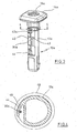
- a sleeve for a neck rest comprising a sleeve body 10 which has a sleeve portion 12 and a head portion 14 which is radially expanded with respect to the sleeve portion 12.
- the head portion 14 has a through opening 16 which is aligned with the interior of the sleeve portion 12 for the reception of a bar of a neck rest, which fact is not shown in detail.
- the lower end of the sleeve portion 12 has opposed snap-in blades 18, 20 which cooperate with respective mating surfaces of a receptacle which is formed in the back rest of an automobile seat. This is not shown either.
- a first resilient portion 22 is formed on below the head 14 and is located within an opening 24.
- a second resilient portion 26 is formed thereon at an axially parallel distance therefrom and is located within an opening 28.
- Fig. 1 further allows to see a wire portion 30 which extends downwards from below the head 14 through a certain length parallel to the axis of the sleeve portion 12 at the outer side of the sleeve portion 12.
- the wire portion 30 is retained by means of two hook shaped portions 32, 34 which extend transversely to the axis of the sleeve portion 12 and are configured so as to clippingly grip over the wire portion 30. This way clippingly locates the wire portion 30 both in the sideward and axial directions.
- the upper and the lower end of the wire portion 30 extend at the outer side of the resilient portions 22, 26 as can be seen from Fig. 2 .
- the wire portion 30 which is circular in cross-section is made of steel, for example.
- the resilient portion 26 and the arrangement of the wire portion 30 is such that if the bar of a neck rest is not received the resilient portion 26 projects slightly into the interior of the sleeve portion 12.
- the contour of the bar for a neck rest is outlined at 36.
- the inner side of the resilient portion 26 abuts against the bar 36 as it is appropriately biased by the wire portion 30.
- a wire portion 30a can be seen which is clippingly located between two portions 40, 42, which fact is not shown in detail. Mounting the wire portion requires to clip it in between the portions 40, 42 the distance of which from each other is smaller than is the diameter of the wire portion 30a. This manner locates the wire portion 30a sufficiently in both the axial and sideward directions.
- the outer side of the sleeve portion 10a has formed thereto two resilient portions 42a, 44 which extend transversely to the axis of the sleeve portion 10a and, along with the outer side of the sleeve portion 12a, define a space as is shown at 46 in Fig. 4 .
- the outer side of the portions 42a and 44 constitutes a bearing area on a respective receptacle for the sleeve portion 12a which is shown by a dash-and-dot line at 48 in Fig. 4 .
- the receptacle 48 is designed as a tubular body.
- Fig. 4 shows the position of the resilient portion 44 before the sleeve portion 12a is introduced into the receptacle 48.
- the outer side of the resilient portion 44 projects beyond the inner side of the receptacle 48.
- the resilient portion 44 will be radially deformed inwards while overcoming the elastic force of the wire portion 30a.
Landscapes
- Engineering & Computer Science (AREA)
- Aviation & Aerospace Engineering (AREA)
- Transportation (AREA)
- Mechanical Engineering (AREA)
- Chair Legs, Seat Parts, And Backrests (AREA)
- Springs (AREA)
- Mutual Connection Of Rods And Tubes (AREA)
Description
- The invention relates to a sleeve for a neck rest with tolerance compensation according to
claims 1 and 2. - It is known that sleeves for neck rests serve for receiving neck rest bars of a neck rest which is attached to seat backs of automobile seats. The sleeves for neck rests are usually provided with means to lock the neck rest bars at different levels. Further, means are provided to eliminate the locked position. The sleeves have an integrally formed neck rest body which is composed of an elongate sleeve portion and an upper radial flange portion which comes to bear against the upper side of the seat back when the sleeve for the neck rest is introduced into the seat back. The flange portion frequently has mounted therein a spring which cooperates with catch recesses of the neck rest bars in order to lock them.
- The sleeve for the neck rest, in turn, is received in a respective receptacle in the seat back. The receptacle can consist of a tubular piece which is inserted into the seat back. Alternatively, other receptacle constructions may be provided which receive the sleeve for the neck rest.
- Both the interior of the sleeve for the neck rest and the outer contour are subjected to tolerances. The neck rest bars and the receptacles in the backs of the seats also feature tolerances. Therefore, care should be taken to provide for an adequate tolerance compensation. In this context, it is known to form a resilient portion integrally with the neck rest body that extends into the interior of the sleeve for the neck rest if a neck rest bar is not introduced. If the bar is introduced the resilient portion will be deformed outwardly and applies a respective pressure to the neck rest bar. As a result, a tolerance compensation is obtained in the interior of the sleeve for the neck rest. Similarly, known sleeves for neck rests provide at least one outer resilient portion which cooperates with the neck rest receptacle when the sleeve for the neck rest is introduced into the receptacle. The disadvantage of such resilient portions is that they gradually lose their resilience property, particularly during temperature variations. The same is the case when ribs or similar protrusions are provided which radially extend into the sleeve for the neck rest or project from their outer side and are supposed to ensure a tolerance compensation. Such protrusions will flow away at higher temperatures and backlash-free tuning is no longer possible.
- It is further known to mount metallic springs on the neck rest body which cooperate with the neck rest bar or neck rest receptacle. The disadvantage of metallic springs is that they involve efforts in manufacture and develop noise when in use.
-
US 6 454 356 B1 discloses a headrest support according to the preamble ofclaims 1 and 2 that absorbs impact occurring in the headrest in the direction of its height. The headrest support is provided with a spring structure formed vertically downward from a lower side of a lock piece retaining hole, which shall prevent the clattering of a tube body relative to a receptacle tube of the headrest support. - It is the object of the invention to provide a tolerance compensation for sleeves for neck rests that is permanently effective and causes a very small effort,
- The invention is defined by the features set forth in
claims 1 and 2. - In the sleeve for a neck rest of claim 1, a wire portion made of resilient metal is mounted in parallel with the axis of the sleeve body at the outer side such that a wire portion can be resiliently deflected away from the sleeve body. The wire portion is located at the outer side of the resilient portion. The wire portion, e.g. of circular steel wire, is extremely easy to manufacture as it is cut off from an endless wire. The wire is appropriately attached to the outer side of the sleeve body and serves as a spring supporting the resilient portion which, in turn, bears on the neck rest bar. It is completely unnecessary here to take into account the inherent elastic force of the resilient portion. The resilient portion, in turn, need merely be elastically deformable because the biasing force proper is applied by the wire portion.
- In the solution of
claim 2, a wire portion is used as well, which engages the inner side of a resilient portion so as to enable it to be biased outwardly against the seat of the sleeve body. - Further features of preferred embodiments of the invention are disclosed in the dependent claims.
- It is preferred to provide at least two spaced resilient portions both during the tolerance compensation of the inner diameter of the sleeve body and during the tolerance compensation of the outer diameter in a longitudinal direction. According to the invention, only a single wire portion is provided the end portions of which cooperate with the resilient portions and which is located between the ends on the neck rest body.
- According to an aspect of the invention, it is preferred that the wire portion be clippingly located by portions at the outer side of the sleeve body. For example, according to an aspect of the invention, a hook shaped portion extending transverse to the axis of the sleeve body may be formed at the outer surface, the wire portion being laterally clipped between the hook shaped portion and the outer surface of the sleeve body, with a free end of the hook gripping over the clipped wire portion at least partially.
- The invention will be described in more detail below with reference to the embodiments shown in the drawings.
-
Fig. 1 shows a perspective view of a sleeve for a neck rest with a tolerance compensation for the inner diameter according to the invention. -
Fig. 2 shows a section through the representation ofFig. 1 along line 2-2. -
Fig. 3 shows a perspective view of a sleeve for a neck rest with a tolerance compensation for the outer diameter according to the invention. -
Fig. 4 shows a section through the representation ofFig. 3 along line 4-4. - In
Fig. 1 , a sleeve for a neck rest is shown comprising asleeve body 10 which has asleeve portion 12 and ahead portion 14 which is radially expanded with respect to thesleeve portion 12. Thehead portion 14 has a through opening 16 which is aligned with the interior of thesleeve portion 12 for the reception of a bar of a neck rest, which fact is not shown in detail. The lower end of thesleeve portion 12 has opposed snap-inblades - In
Fig. 1 , it can be seen that a firstresilient portion 22 is formed on below thehead 14 and is located within an opening 24. A secondresilient portion 26 is formed thereon at an axially parallel distance therefrom and is located within an opening 28. -
Fig. 1 further allows to see awire portion 30 which extends downwards from below thehead 14 through a certain length parallel to the axis of thesleeve portion 12 at the outer side of thesleeve portion 12. Thewire portion 30 is retained by means of two hook shapedportions sleeve portion 12 and are configured so as to clippingly grip over thewire portion 30. This way clippingly locates thewire portion 30 both in the sideward and axial directions. The upper and the lower end of thewire portion 30 extend at the outer side of theresilient portions Fig. 2 . Thewire portion 30 which is circular in cross-section is made of steel, for example. Theresilient portion 26 and the arrangement of thewire portion 30 is such that if the bar of a neck rest is not received theresilient portion 26 projects slightly into the interior of thesleeve portion 12. The contour of the bar for a neck rest is outlined at 36. Thus, the inner side of theresilient portion 26 abuts against thebar 36 as it is appropriately biased by thewire portion 30. - The sleeve for a neck rest of
Fig. 3 is largely the same as that ofFig. 1 . Therefore, identical parts are given the same reference numbers to which an a is added. Again, awire portion 30a can be seen which is clippingly located between twoportions portions wire portion 30a. This manner locates thewire portion 30a sufficiently in both the axial and sideward directions. - The outer side of the
sleeve portion 10a has formed thereto tworesilient portions 42a, 44 which extend transversely to the axis of thesleeve portion 10a and, along with the outer side of thesleeve portion 12a, define a space as is shown at 46 inFig. 4 . The outer side of theportions 42a and 44 constitutes a bearing area on a respective receptacle for thesleeve portion 12a which is shown by a dash-and-dot line at 48 inFig. 4 . In the present case, thereceptacle 48 is designed as a tubular body.Fig. 4 shows the position of theresilient portion 44 before thesleeve portion 12a is introduced into thereceptacle 48. It can be recognized that the outer side of theresilient portion 44 projects beyond the inner side of thereceptacle 48. When thesleeve portion 12a is introduced into thereceptacle 48 theresilient portion 44 will be radially deformed inwards while overcoming the elastic force of thewire portion 30a.
Claims (5)
- A sleeve for a neck rest with tolerance compensation, comprising a sleeve body (10) of plastic material for the accommodation of a rod of the neck rest, the sleeve body (12) including at least one integrally formed resilient portion (22, 26) which is biased towards the interior of a sleeve body against an accommodated rod, characterized in that a wire portion (30) is attached to the outer side of the sleeve body (12) parallel to the axis of the sleeve body such that the wire portion can be resiliently deflected away from the sleeve body (12), the wire portion engaging the outer side of the resilient portion (22, 26).
- A sleeve for a neck rest with tolerance compensation, comprising a sleeve body (12a) of plastic material for the accommodation of a neck rest rod, the sleeve body (12a) including at least one integrally formed resilient portion (42a, 44) which is biased outwardly away from the sleeve body upon accommodation in receiving means, characterized in that a wire portion (30a) of resilient metal is attached to the sleeve body (12a) parallel to the axis thereof such that the wire portion may be resiliently deflected towards the sleeve body (12a), the wire portion engaging the inner side of the resilient portion (42a, 44).
- The sleeve of claim 1 or 2, wherein two resilient portions (22, 26; 42a, 44) are formed to the sleeve body (12), the resilient portions being spaced in longitudinal direction of the sleeve body (12), and a single wire portion (30, 30a) is attached to the sleeve body (12, 12a) and has end portions which engage the resilient portions.
- The sleeve of one of the claims 1 to 3, wherein the wire portion (30, 30a) is clampingly fixed to the outer side of the sleeve body (12, 12a) through portions (40, 42a) integrally formed with the sleeve body.
- The sleeve of claim 4, wherein at least one hook shaped portion (32, 34) extending transverse to the axis of the sleeve body (12) is formed to the sleeve body (12), the wire portion (30) being adapted to be laterally clipped between the hook shaped portion (32) and the outer surface of the sleeve body, with a free end of the hook portion (32, 34) at least partially gripping over the wire portion (30).
Applications Claiming Priority (2)
| Application Number | Priority Date | Filing Date | Title |
|---|---|---|---|
| DE202004009769U DE202004009769U1 (en) | 2004-06-22 | 2004-06-22 | Headrest sleeve with tolerance compensation |
| DE202004009769U | 2004-06-22 |
Publications (3)
| Publication Number | Publication Date |
|---|---|
| EP1609665A2 EP1609665A2 (en) | 2005-12-28 |
| EP1609665A3 EP1609665A3 (en) | 2009-12-16 |
| EP1609665B1 true EP1609665B1 (en) | 2011-08-24 |
Family
ID=34936992
Family Applications (1)
| Application Number | Title | Priority Date | Filing Date |
|---|---|---|---|
| EP05011472A Expired - Lifetime EP1609665B1 (en) | 2004-06-22 | 2005-05-27 | Sleeve for a head rest with tolerance compensation |
Country Status (4)
| Country | Link |
|---|---|
| US (1) | US7429086B2 (en) |
| EP (1) | EP1609665B1 (en) |
| DE (1) | DE202004009769U1 (en) |
| ES (1) | ES2372052T3 (en) |
Cited By (1)
| Publication number | Priority date | Publication date | Assignee | Title |
|---|---|---|---|---|
| WO2016198692A1 (en) | 2015-06-11 | 2016-12-15 | Johnson Controls Gmbh | Guide sleeve for a vehicle seat |
Families Citing this family (14)
| Publication number | Priority date | Publication date | Assignee | Title |
|---|---|---|---|---|
| WO2008046198A1 (en) * | 2006-10-13 | 2008-04-24 | Intier Automotive Inc. | Head restraint sleeve |
| JP5243381B2 (en) * | 2009-10-05 | 2013-07-24 | 三協株式会社 | Headrest support device |
| DE102010010978B4 (en) | 2010-03-10 | 2011-11-10 | Faurecia Autositze Gmbh | Headrest sleeve for receiving a headrest rod |
| FR2979592B1 (en) * | 2011-09-02 | 2013-10-04 | Cera | DEVICE FOR RECEIVING THE SLIDING HEAD OF A HEADREST FOR THE SEAT OF A MOTOR VEHICLE |
| ES2582082T3 (en) | 2012-12-28 | 2016-09-09 | Illinois Tool Works Inc. | Headrest guide device |
| FR3006953B1 (en) * | 2013-06-12 | 2015-07-17 | Cera | DEVICE FOR MOUNTING A HEADREST ON A SEAT BACK OF A MOTOR VEHICLE |
| ES2541694B1 (en) * | 2014-01-23 | 2016-05-12 | Illinois Tool Works Inc. | Headrest retention device for vehicles |
| DE102015221207A1 (en) | 2015-10-29 | 2017-05-04 | Bayerische Motoren Werke Aktiengesellschaft | Headrest support for a seat, in particular a motor vehicle seat |
| JP6768565B2 (en) * | 2017-03-10 | 2020-10-14 | 日本発條株式会社 | Headrest support structure |
| EP3885188A1 (en) | 2020-03-24 | 2021-09-29 | Illinois Tool Works INC. | Sleeve for headrest |
| CN117043005A (en) | 2021-03-04 | 2023-11-10 | 伊利诺斯工具制品有限公司 | Retaining insert for headrest sleeve device and sleeve device assembly thereof |
| EP4056417B1 (en) | 2021-03-11 | 2026-01-28 | Illinois Tool Works, Inc. | Sleeve device for a headrest |
| US12240365B2 (en) | 2021-09-08 | 2025-03-04 | Illinois Tool Works Inc. | Sleeve device for a headrest |
| DE102024127970A1 (en) * | 2023-10-06 | 2025-04-10 | Illinois Tool Works Inc. | SLEEVE DEVICE FOR A HEADREST |
Family Cites Families (8)
| Publication number | Priority date | Publication date | Assignee | Title |
|---|---|---|---|---|
| DE3323229A1 (en) * | 1983-06-28 | 1985-01-10 | Eugen Otto 4010 Hilden Butz | Head restraints for motor vehicles |
| DE3436540A1 (en) * | 1984-10-05 | 1986-04-10 | Daimler-Benz Ag, 7000 Stuttgart | LIMITATION SECURITY FOR A GUIDED SUPPORT ROD OF A HEADREST |
| GB2246952B (en) * | 1990-07-17 | 1994-05-11 | Schmidt Gmbh R | Head rest for fitting in motor vehicles |
| DE4409557C2 (en) * | 1994-03-19 | 2002-11-07 | Itw Ateco Gmbh | Guide sleeve for headrests on vehicle seats |
| US5992939A (en) * | 1997-09-22 | 1999-11-30 | Illinois Tool Works Inc. | Head rest sleeve |
| WO2000010430A1 (en) * | 1998-08-25 | 2000-03-02 | Nihon Technica Co., Ltd. | Head rest support |
| FR2849813B1 (en) * | 2003-01-15 | 2005-03-25 | Faurecia Sieges Automobile | HEADREST DEVICE FOR VEHICLE SEAT AND VEHICLE SEAT COMPRISING SUCH A DEVICE |
| US7108327B2 (en) * | 2004-09-23 | 2006-09-19 | Lear Corporation | Adjustable head restraint guide |
-
2004
- 2004-06-22 DE DE202004009769U patent/DE202004009769U1/en not_active Expired - Lifetime
-
2005
- 2005-05-27 EP EP05011472A patent/EP1609665B1/en not_active Expired - Lifetime
- 2005-05-27 ES ES05011472T patent/ES2372052T3/en not_active Expired - Lifetime
- 2005-06-21 US US11/156,562 patent/US7429086B2/en active Active
Cited By (2)
| Publication number | Priority date | Publication date | Assignee | Title |
|---|---|---|---|---|
| WO2016198692A1 (en) | 2015-06-11 | 2016-12-15 | Johnson Controls Gmbh | Guide sleeve for a vehicle seat |
| US10434915B2 (en) | 2015-06-11 | 2019-10-08 | Adient Luxembourg Holding S.à.r.l. | Guide sleeve for a vehicle seat |
Also Published As
| Publication number | Publication date |
|---|---|
| EP1609665A3 (en) | 2009-12-16 |
| US20060012225A1 (en) | 2006-01-19 |
| DE202004009769U1 (en) | 2005-11-17 |
| ES2372052T3 (en) | 2012-01-13 |
| US7429086B2 (en) | 2008-09-30 |
| EP1609665A2 (en) | 2005-12-28 |
Similar Documents
| Publication | Publication Date | Title |
|---|---|---|
| US7429086B2 (en) | Sleeve for a neck rest with tolerance compensation | |
| US7165814B2 (en) | Sleeve arrangement for a neck rest | |
| EP2108287B1 (en) | Attaching device for end of spring | |
| EP2181019B1 (en) | Guide sleeve for a retaining rod of a neck rest | |
| EP2749448B1 (en) | A sleeve device for a headrest | |
| CN107635828B (en) | Guide sleeve for vehicle seat | |
| CN108928278B (en) | Grommet | |
| RU2705607C2 (en) | Retainer for cup holder incorporating integral preloaded retainer clip | |
| EP1432598B1 (en) | Mounting structure of a vehicle interior part | |
| US7984945B2 (en) | Reduced thickness vehicle seat with active headrest | |
| JP6229687B2 (en) | Mounting clip and attachment mounting structure using the same | |
| CN107848452B (en) | Headrest body and headrest | |
| CA2519430A1 (en) | Disk brake, in particular for utility vehicles | |
| EP2628961B1 (en) | Clip and fastening arrangement with a clip | |
| CN112664602B (en) | Friction damper | |
| WO2008046198A1 (en) | Head restraint sleeve | |
| KR101683428B1 (en) | Headrest guide assembly for seat | |
| KR20230060350A (en) | Assembly structure of coat hook for vehicle | |
| CN108040477A (en) | Protection element, seat for seat | |
| WO1999058365A1 (en) | Pivotable arm rest with retaining spring | |
| US10207610B2 (en) | Articulating locking mechanism for a seatback | |
| JP2001271864A (en) | Bound stopper | |
| CN115107611B (en) | Headrest support of automobile seat | |
| JP7745423B2 (en) | Holder | |
| KR20070090593A (en) | Structure of Car Cup Holder Stopper |
Legal Events
| Date | Code | Title | Description |
|---|---|---|---|
| PUAI | Public reference made under article 153(3) epc to a published international application that has entered the european phase |
Free format text: ORIGINAL CODE: 0009012 |
|
| 17P | Request for examination filed |
Effective date: 20050603 |
|
| AK | Designated contracting states |
Kind code of ref document: A2 Designated state(s): AT BE BG CH CY CZ DE DK EE ES FI FR GB GR HU IE IS IT LI LT LU MC NL PL PT RO SE SI SK TR |
|
| AX | Request for extension of the european patent |
Extension state: AL BA HR LV MK YU |
|
| RAP1 | Party data changed (applicant data changed or rights of an application transferred) |
Owner name: ITW AUTOMOTIVE PRODUCTS GMBH & CO. KG |
|
| PUAL | Search report despatched |
Free format text: ORIGINAL CODE: 0009013 |
|
| AK | Designated contracting states |
Kind code of ref document: A3 Designated state(s): AT BE BG CH CY CZ DE DK EE ES FI FR GB GR HU IE IS IT LI LT LU MC NL PL PT RO SE SI SK TR |
|
| AX | Request for extension of the european patent |
Extension state: AL BA HR LV MK YU |
|
| 17Q | First examination report despatched |
Effective date: 20100614 |
|
| AKX | Designation fees paid |
Designated state(s): DE ES FR GB IT |
|
| GRAP | Despatch of communication of intention to grant a patent |
Free format text: ORIGINAL CODE: EPIDOSNIGR1 |
|
| RIC1 | Information provided on ipc code assigned before grant |
Ipc: B60N 2/48 20060101AFI20110228BHEP |
|
| GRAS | Grant fee paid |
Free format text: ORIGINAL CODE: EPIDOSNIGR3 |
|
| GRAA | (expected) grant |
Free format text: ORIGINAL CODE: 0009210 |
|
| AK | Designated contracting states |
Kind code of ref document: B1 Designated state(s): DE ES FR GB IT |
|
| REG | Reference to a national code |
Ref country code: GB Ref legal event code: FG4D |
|
| REG | Reference to a national code |
Ref country code: DE Ref legal event code: R096 Ref document number: 602005029663 Country of ref document: DE Effective date: 20111027 |
|
| REG | Reference to a national code |
Ref country code: ES Ref legal event code: FG2A Ref document number: 2372052 Country of ref document: ES Kind code of ref document: T3 Effective date: 20120113 |
|
| PG25 | Lapsed in a contracting state [announced via postgrant information from national office to epo] |
Ref country code: IT Free format text: LAPSE BECAUSE OF FAILURE TO SUBMIT A TRANSLATION OF THE DESCRIPTION OR TO PAY THE FEE WITHIN THE PRESCRIBED TIME-LIMIT Effective date: 20110824 |
|
| PLBE | No opposition filed within time limit |
Free format text: ORIGINAL CODE: 0009261 |
|
| STAA | Information on the status of an ep patent application or granted ep patent |
Free format text: STATUS: NO OPPOSITION FILED WITHIN TIME LIMIT |
|
| 26N | No opposition filed |
Effective date: 20120525 |
|
| REG | Reference to a national code |
Ref country code: DE Ref legal event code: R097 Ref document number: 602005029663 Country of ref document: DE Effective date: 20120525 |
|
| PGFP | Annual fee paid to national office [announced via postgrant information from national office to epo] |
Ref country code: ES Payment date: 20120528 Year of fee payment: 8 |
|
| GBPC | Gb: european patent ceased through non-payment of renewal fee |
Effective date: 20120527 |
|
| PG25 | Lapsed in a contracting state [announced via postgrant information from national office to epo] |
Ref country code: GB Free format text: LAPSE BECAUSE OF NON-PAYMENT OF DUE FEES Effective date: 20120527 |
|
| REG | Reference to a national code |
Ref country code: DE Ref legal event code: R081 Ref document number: 602005029663 Country of ref document: DE Owner name: ITW AUTOMOTIVE PRODUCTS GMBH, DE Free format text: FORMER OWNER: ITW AUTOMOTIVE PRODUCTS GMBH, 58642 ISERLOHN, DE Effective date: 20130502 Ref country code: DE Ref legal event code: R081 Ref document number: 602005029663 Country of ref document: DE Owner name: ITW AUTOMOTIVE PRODUCTS GMBH, DE Free format text: FORMER OWNER: ITW AUTOMOTIVE PRODUCTS GMBH & CO. KG, 58636 ISERLOHN, DE Effective date: 20110906 |
|
| REG | Reference to a national code |
Ref country code: ES Ref legal event code: FD2A Effective date: 20140613 |
|
| PG25 | Lapsed in a contracting state [announced via postgrant information from national office to epo] |
Ref country code: ES Free format text: LAPSE BECAUSE OF NON-PAYMENT OF DUE FEES Effective date: 20130528 |
|
| REG | Reference to a national code |
Ref country code: FR Ref legal event code: PLFP Year of fee payment: 12 |
|
| REG | Reference to a national code |
Ref country code: FR Ref legal event code: PLFP Year of fee payment: 13 |
|
| REG | Reference to a national code |
Ref country code: DE Ref legal event code: R079 Ref document number: 602005029663 Country of ref document: DE Free format text: PREVIOUS MAIN CLASS: B60N0002480000 Ipc: B60N0002800000 |
|
| REG | Reference to a national code |
Ref country code: FR Ref legal event code: PLFP Year of fee payment: 14 |
|
| PGFP | Annual fee paid to national office [announced via postgrant information from national office to epo] |
Ref country code: FR Payment date: 20200525 Year of fee payment: 16 |
|
| PG25 | Lapsed in a contracting state [announced via postgrant information from national office to epo] |
Ref country code: FR Free format text: LAPSE BECAUSE OF NON-PAYMENT OF DUE FEES Effective date: 20210531 |
|
| P01 | Opt-out of the competence of the unified patent court (upc) registered |
Effective date: 20231101 |
|
| PGFP | Annual fee paid to national office [announced via postgrant information from national office to epo] |
Ref country code: DE Payment date: 20240530 Year of fee payment: 20 |
|
| REG | Reference to a national code |
Ref country code: DE Ref legal event code: R071 Ref document number: 602005029663 Country of ref document: DE |