EP1609600A1 - Inkjet system, method of making this system, and use of said system - Google Patents
Inkjet system, method of making this system, and use of said system Download PDFInfo
- Publication number
- EP1609600A1 EP1609600A1 EP05105461A EP05105461A EP1609600A1 EP 1609600 A1 EP1609600 A1 EP 1609600A1 EP 05105461 A EP05105461 A EP 05105461A EP 05105461 A EP05105461 A EP 05105461A EP 1609600 A1 EP1609600 A1 EP 1609600A1
- Authority
- EP
- European Patent Office
- Prior art keywords
- signal
- actuator
- natural frequency
- ink
- disturbance
- Prior art date
- Legal status (The legal status is an assumption and is not a legal conclusion. Google has not performed a legal analysis and makes no representation as to the accuracy of the status listed.)
- Granted
Links
- 238000004519 manufacturing process Methods 0.000 title claims description 4
- 239000000463 material Substances 0.000 claims description 4
- 238000010586 diagram Methods 0.000 description 9
- 238000004458 analytical method Methods 0.000 description 8
- 238000000034 method Methods 0.000 description 7
- 239000007788 liquid Substances 0.000 description 5
- 230000015572 biosynthetic process Effects 0.000 description 2
- 238000004364 calculation method Methods 0.000 description 2
- 238000006243 chemical reaction Methods 0.000 description 2
- 238000010276 construction Methods 0.000 description 2
- 230000001419 dependent effect Effects 0.000 description 2
- 230000003321 amplification Effects 0.000 description 1
- 238000005352 clarification Methods 0.000 description 1
- 239000003086 colorant Substances 0.000 description 1
- 238000013016 damping Methods 0.000 description 1
- 230000007547 defect Effects 0.000 description 1
- 238000011835 investigation Methods 0.000 description 1
- 238000003199 nucleic acid amplification method Methods 0.000 description 1
Images




Classifications
-
- B—PERFORMING OPERATIONS; TRANSPORTING
- B41—PRINTING; LINING MACHINES; TYPEWRITERS; STAMPS
- B41J—TYPEWRITERS; SELECTIVE PRINTING MECHANISMS, i.e. MECHANISMS PRINTING OTHERWISE THAN FROM A FORME; CORRECTION OF TYPOGRAPHICAL ERRORS
- B41J2/00—Typewriters or selective printing mechanisms characterised by the printing or marking process for which they are designed
- B41J2/005—Typewriters or selective printing mechanisms characterised by the printing or marking process for which they are designed characterised by bringing liquid or particles selectively into contact with a printing material
- B41J2/01—Ink jet
- B41J2/015—Ink jet characterised by the jet generation process
- B41J2/04—Ink jet characterised by the jet generation process generating single droplets or particles on demand
- B41J2/045—Ink jet characterised by the jet generation process generating single droplets or particles on demand by pressure, e.g. electromechanical transducers
- B41J2/04501—Control methods or devices therefor, e.g. driver circuits, control circuits
- B41J2/04581—Control methods or devices therefor, e.g. driver circuits, control circuits controlling heads based on piezoelectric elements
-
- B—PERFORMING OPERATIONS; TRANSPORTING
- B41—PRINTING; LINING MACHINES; TYPEWRITERS; STAMPS
- B41J—TYPEWRITERS; SELECTIVE PRINTING MECHANISMS, i.e. MECHANISMS PRINTING OTHERWISE THAN FROM A FORME; CORRECTION OF TYPOGRAPHICAL ERRORS
- B41J2/00—Typewriters or selective printing mechanisms characterised by the printing or marking process for which they are designed
- B41J2/005—Typewriters or selective printing mechanisms characterised by the printing or marking process for which they are designed characterised by bringing liquid or particles selectively into contact with a printing material
- B41J2/01—Ink jet
- B41J2/015—Ink jet characterised by the jet generation process
- B41J2/04—Ink jet characterised by the jet generation process generating single droplets or particles on demand
- B41J2/045—Ink jet characterised by the jet generation process generating single droplets or particles on demand by pressure, e.g. electromechanical transducers
- B41J2/04501—Control methods or devices therefor, e.g. driver circuits, control circuits
- B41J2/04555—Control methods or devices therefor, e.g. driver circuits, control circuits detecting current
-
- B—PERFORMING OPERATIONS; TRANSPORTING
- B41—PRINTING; LINING MACHINES; TYPEWRITERS; STAMPS
- B41J—TYPEWRITERS; SELECTIVE PRINTING MECHANISMS, i.e. MECHANISMS PRINTING OTHERWISE THAN FROM A FORME; CORRECTION OF TYPOGRAPHICAL ERRORS
- B41J2/00—Typewriters or selective printing mechanisms characterised by the printing or marking process for which they are designed
- B41J2/005—Typewriters or selective printing mechanisms characterised by the printing or marking process for which they are designed characterised by bringing liquid or particles selectively into contact with a printing material
- B41J2/01—Ink jet
- B41J2/07—Ink jet characterised by jet control
- B41J2/125—Sensors, e.g. deflection sensors
-
- B—PERFORMING OPERATIONS; TRANSPORTING
- B41—PRINTING; LINING MACHINES; TYPEWRITERS; STAMPS
- B41J—TYPEWRITERS; SELECTIVE PRINTING MECHANISMS, i.e. MECHANISMS PRINTING OTHERWISE THAN FROM A FORME; CORRECTION OF TYPOGRAPHICAL ERRORS
- B41J2/00—Typewriters or selective printing mechanisms characterised by the printing or marking process for which they are designed
- B41J2/005—Typewriters or selective printing mechanisms characterised by the printing or marking process for which they are designed characterised by bringing liquid or particles selectively into contact with a printing material
- B41J2/01—Ink jet
- B41J2/17—Ink jet characterised by ink handling
- B41J2/19—Ink jet characterised by ink handling for removing air bubbles
-
- B—PERFORMING OPERATIONS; TRANSPORTING
- B41—PRINTING; LINING MACHINES; TYPEWRITERS; STAMPS
- B41J—TYPEWRITERS; SELECTIVE PRINTING MECHANISMS, i.e. MECHANISMS PRINTING OTHERWISE THAN FROM A FORME; CORRECTION OF TYPOGRAPHICAL ERRORS
- B41J2/00—Typewriters or selective printing mechanisms characterised by the printing or marking process for which they are designed
- B41J2/005—Typewriters or selective printing mechanisms characterised by the printing or marking process for which they are designed characterised by bringing liquid or particles selectively into contact with a printing material
- B41J2/01—Ink jet
- B41J2/135—Nozzles
- B41J2/14—Structure thereof only for on-demand ink jet heads
- B41J2002/14354—Sensor in each pressure chamber
Definitions
- the invention relates to an inkjet system comprising a printhead comprising an ink-fillable chamber operatively connected to a piezoelectric actuator and provided with a nozzle for the ejection of ink drops in response to energisation of the actuator, which actuator is connected to a measuring circuit for measuring an electric signal generated by the actuator in response to a deformation thereof.
- the invention also relates to a method of making such a system and use of said system in forming an image on a receiving material.
- a system of this kind is known from European Application EP 1 013 453.
- This system forms part of an inkjet printer with which receiving materials can be printed.
- the known system is of the piezo type and has a printhead with an ink chamber (also termed an "ink duct” or, briefly, a "duct") operatively connected to a piezoelectric actuator.
- the ink chamber has a flexible wall which is deformable by energisation of the actuator connected to said wall. Deformation of the wall results in an acoustic pressure wave in the chamber which, given adequate strength, will result in ejection of an ink drop from the nozzle of that chamber.
- the pressure wave in turn, however, results in a deformation of the wall, and this can be fed to the piezoelectric actuator. This will generate an electric signal under the influence of its deformation.
- a disadvantage of the known method is that the signal generated by the piezoelectric actuator in response to its deformation by the pressure wave in the duct, is often very complex, apart from the possible presence of random disturbances (noise). It has been found that the pressure wave in the duct is not a simple sine or some other simple wave. That would in fact result in a comparably simple electric signal. Apparently the pressure wave is not solely determined by the deformation of the actuator directly preceding the drop ejection, but there are also a number of other events which influence the pressure wave. Another consequence of this complex pressure wave is that the signal generated by the actuator as a result of this pressure wave is also very complex. Analysis of such a complex signal requires a complex, preferably digital, measuring circuit and/or relatively long processing times.
- the object of the invention is to provide a method whereby the above-described disadvantages are obviated.
- a method has been invented wherein the system is so configured that a natural frequency of said system corresponds substantially to a natural frequency of a disturbance in the system.
- the advantage of this system is that the disturbance is expressed relatively strongly in the electric signal generated by the piezoelectric actuator as a result of its deformation by the pressure wave. Resonance of the disturbance takes place namely at a frequency which is just provided by the system. This means that the analysis of the signal can remain restricted to a small area around the natural frequency of the system and also it is possible to use simple electronics, precisely because the contribution in the electric signal as a result of the disturbance is amplified by the system.
- the natural frequency of the system should be exactly equal to the natural frequency of the disturbance. Since there is a region around the natural frequency of the system, or a "window", where there is already amplification in the signal, it is sufficient for the window to enclose the natural frequency of the disturbance. In this way the natural frequencies correspond to one another sufficiently.
- an inkjet system of the piezo type has one or more natural frequencies. If, for example, an acoustic pressure wave were generated in the ink chamber in which each frequency is represented equally strongly (known as "white noise"), then the electric signal received by the measuring circuit will have a number of frequencies at which said signal is relatively strong (first, second and other harmonic frequencies). These frequencies are termed natural frequencies. Investigation has shown that the position of these natural frequencies should be controlled because this appears to be dependent on the configuration of the system. For example, the position can be influenced by adapting the geometry of the ink chamber, the geometry of the nozzle, the type of ink, the type of actuator, and so on.
- a configuration with which a natural frequency of the system coincides with a natural frequency of a disturbance can be found by experimentation, for example by adapting the geometry of the duct, and/or the geometry of an inflow opening of the duct, and/or the geometry of the nozzle, and/or the geometry and/or the construction of the piezo actuator, and/or the type of ink (in brief anything that influences the natural frequencies of the system), and determining the natural frequency or frequencies in each case. It can also be determined by calculation by the use of a suitable acoustic model of the system. A natural frequency of a disturbance can also be determined experimentally or by calculation.
- a disturbance in the context of the present invention is an irregularity in the system regarded as unacceptable. This can, for example, be the case if the irregularity can result in a print artefact visible to the human eye in the printed image, or if the irregularity can result in damage to the printer.
- the unacceptability of an irregularity may vary from one application to another.
- a natural frequency of the system corresponds substantially to a natural frequency of an air bubble of a size such that it noticeably influences the ejection of ink drops.
- one or more air bubbles may be located in an ink duct. On the one hand, they can be present in the ink itself and possibly even grow in the ink duct, on the other hand they can also form in the ink duct, particularly because of negative pressures which can be generated in the ink duct (cavitation). Many of these air bubbles, however, are not a disturbance in the sense of the present invention. They are often so small that they have no noticeable influence on the jetting process and disappear automatically after a specific time or after a number of energisations of the actuator.
- a critical value can be determined for an air bubble at which it just noticeably will influence the ejection of the ink drops.
- the natural frequency of an air bubble having this critical value just falls in the window around the natural frequency of the system. In this way, air bubbles which have a size below the critical value can simply be disregarded. As soon as a bubble becomes so great that it can be regarded as a disturbance, it can simply be rendered visible in the signal generated by the actuator.
- the measuring circuit comprises a mixer in order to mix with the signal a frequency equal to the natural frequency of the system.
- a mixer in order to mix with the signal a frequency equal to the natural frequency of the system.
- the invention also covers a method of making an inkjet system comprising forming an ink chamber with a nozzle for the ejection of ink drops from said chamber, which ink chamber is operatively connected to a piezoelectric actuator, connecting the actuator to a measuring circuit, wherein the system is so configured that a natural frequency of said system is substantially equal to a natural frequency of a disturbance in the system.
- the invention also relates to application of the above-described system to the formation of an image on a receiving material.
- Fig. 1 diagrammatically illustrates an inkjet printer.
- the printer comprises a roller 10 to support a receiving medium 12 and guided along the four printheads 16.
- the roller 10 is rotatable about its axis as indicated by arrow A.
- a carriage 14 carries the four printheads 16, one for each of the colours cyan, magenta, yellow and black, and can be moved in reciprocation in a direction indicated by the double arrow B, parallel to the roller 10. In this way the printheads 16 can scan the receiving medium 12.
- the carriage 14 is guided over rods 18 and 20 and is driven by suitable means (not shown).
- each printhead 16 comprises eight ink chambers, each with its own nozzle 22, which form an imaginary line perpendicular to the axis of the roller 10.
- the number of ink chambers per printhead 16 is many times greater.
- Each ink chamber is provided with a piezoelectric actuator (not shown) and associated actuation and measuring circuit (not shown) as described in connection with Figs. 2 and 3.
- Each of the printheads also comprises a control unit for adapting the actuation pulses. In this way, the ink chamber, actuator, actuation circuit, measuring circuit and control unit form a system serving to eject ink drops in the direction of the roller 10.
- control unit and/or for example all the elements of the actuation and measuring circuit are physically integrated in the actual printheads 16. It is also possible for these parts to be disposed, for example, in the carriage 14 or even in a more remote part of the printer, there being connections to components in the printheads themselves. In this way, however, these parts form a functional component of the printheads without actually being physically built in to the printheads. If the actuators are actuated imagewise, an image forms which is built up from individual ink drops on the receiving medium 12.
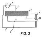
- an ink chamber 5 is provided with an electromechanical actuator 2, in this example a piezoelectric actuator.
- Ink chamber 5 is formed by a groove in baseplate 1 and is bounded at the top mainly by the piezoelectric actuator 2.
- the ink chamber 5 merges into a nozzle 22, the opening being formed by a nozzle plate 6 in which there is a recess at the location of the duct.
- Fig. 3 diagrammatically shows the conversion of an acoustic signal to an electric signal.
- Fig. 3a shows an inkjet printhead 16.
- the printhead is provided with nozzles 22 at the front.
- Each of the ink chambers corresponding to the nozzles 22 is connected to a measuring circuit 31 via line 30.
- Fig. 3a shows only one ink chamber in actual fact as connected to a measuring circuit.
- the measuring circuit can be constructed in various ways as is sufficiently known from the prior art, for example from European Patent Applications EP 1 378 359, EP 1 378 360 and EP 1 378 361.
- the measuring circuit 31 is in turn connected to control unit 32 which processes the data coming from the measuring circuit and uses them in controlling the ink chambers of the printhead 16.
- the control unit is provided with a line 33.
- Fig. 3b diagrammatically shows how the inkjet system as described in Fig. 2 converts an acoustic vibration (pressure wave) in the ink duct into an electric signal.
- the vertical axis in this drawing shows a signal strength in arbitrary units H while the horizontal axis plots the frequency f.
- the piezoelectric actuator would in response to deformation as a result of the corresponding pressure wave deliver an electric signal 41 to the measuring circuit. It will be seen that this signal has a number of natural frequencies 41-1, 41-2, 41-3, etc. This means that a pressure wave having a frequency corresponding to the natural frequencies is reflected relatively strongly in said electric signal.
- the position of the natural frequencies is determined by the configuration of the system. With a different nozzle size or shape, for example, the natural frequencies shift to different positions.
- the duct length, cross-section, shape and size of the filling opening, and also the type of ink, type of actuator, mechanical construction of the printhead, etc., also influence the position of the natural frequencies. This offers the possibility of placing the one or more natural frequencies at preselected positions.
- Fig. 3b also shows windows 42, 43 and 44 around the natural frequencies. These windows can be arbitrarily selected. In this example, the boundaries of the window correspond to the frequency range considered.
- Fig. 4 is a diagram showing part of a measuring circuit 31 of the kind that can be used in an inkjet system as known from the prior art.
- the entire signal such as the piezoelectric actuator generates it is analysed.
- a signal of this kind can be complex. Complex digital electronics are therefore often used for its analysis.
- One way in which this can be implemented is shown in the drawing, which illustrates a specific embodiment 31 a of a (part of the) measuring circuit.
- Component 45 is a front-end unit which converts to a voltage signal the incoming current signal as generated by the actuator. This signal is then fed to an A/D converter 46 to make the signal suitable for processing by digital unit 47.
- This digital signal processor processes the signal so that it can be analysed in analysing unit 48 by the use of an adequate algorithm, particularly in order to prevent disturbances such as air bubbles.
- the control unit (not shown) is informed whether the duct is or is not free of disturbances. If not, then if this is relevant, information concerning the type of disturbance is transmitted so that adequate action can be taken to remove it. In particular the components 47 and 48 make this measuring circuit expensive and that application is therefore not attractive economically.
- Fig. 5 diagrammatically illustrates an air bubble in an infinitely large quantity of liquid.
- This air bubble 100 is illustrated in Fig. 5a.
- This bubble has a radius r.
- the bubble will resonate. This depends on the density of the liquid, the radius of the bubble and so on.
- FIG. 5b A simple model that can be used to determine a resonant frequency of an air bubble is shown in Fig. 5b.
- This model represents the air bubble as a mass-spring system. Both the mass 101 and the spring constant of the spring 102 are a function of the radius of the bubble.
- the resonant frequency of an air bubble located in the finite quantity of ink in an ink duct is not exactly equal to the resonant frequency of the same air bubble located in an infinitely large quantity of liquid.
- the dimensions of the bubble are sufficiently small with respect to the dimensions of the duct, the difference will not be relevant to the practical application of the invention. Since the air bubbles in an ink duct frequently grow from very small bubbles to larger bubbles, they can be detected at a time they are still small enough with respect to the dimensions of the duct.
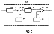
- Fig. 6 is a diagram showing part of the measuring circuit of the kind that can be used in the present invention.
- the measuring circuit 31 b comprises a driver and front-end unit 50 to receive the incoming signal and convert it into a voltage signal f s .
- This signal f s is fed via line 51 to a multiplier 52.
- This natural frequency f x is generated by oscillator 54 and fed to the multiplier 52 via line 53.
- the mixed signal is fed via line 60 to the low-pass filter 61.
- the filtered signal is fed via line 62 to comparator 63 and compared with a reference signal generated by unit 65 and fed via line 64 to the same amplifier. If the filtered signal is completely below the reference signal, then "nozzle OK" is fed as the status via line 70 to the control unit. If the filtered signal is above the reference signal, then the status "nozzle not OK” is fed to the control unit, with or without supplementary information concerning the type and nature of the disturbance.
- each of the ink ducts of the inkjet printhead according to this example is connected to a measuring circuit of this kind.
- Fig. 7 diagrammatically illustrates signals of the kind that can occur in the system according to this invention.
- a signal is in each case plotted in arbitrary strength units on the vertical axis against the frequency on the horizontal axis.
- a signal is shown in each case of the kind that can occur in line 51 (see Fig. 6).
- the fixed signal f x is given in each case with which the incoming signal f s is mixed.
- the resulting mixed signal is given in each case as it may occur in line 60 (see Fig. 6).
- the way in which the filtered signal is compared with a reference signal is shown in each case.
- Fig. 7 relates to a duct without any disturbance.
- the incoming signal is shown (in this example it is simplified to a signal having a main frequency f s and a small signal at the natural frequency f e of the system).
- This signal is mixed with the natural frequency f x of the system.
- the result is the signal shown under c).
- This signal is filtered using the low-pass filter 200.
- the filtered signal is shown under d) (continuous line).
- the reference signal 201 is also shown in the drawing under d). It will be seen that the filtered signal is completely below the reference signal. This corresponds to the status "OK" for the ink duct in question.
- Fig. 7b relates to an ink duct that does have a disturbance.
- the disturbance is an air bubble of a size just equal to the critical size.
- the incoming signal has an extra peak at a frequency corresponding to the natural frequency of the air bubble, i.e. f b .
- This frequency f b corresponds to the natural frequency f x of the system as shown under b).
- the signal as shown under c) is obtained by mixing the two signals.
- This signal has a first peak at the frequency f x -f b ⁇ 0, a second peak at the frequency f x -f s , a third peak at the frequency f x +f s , and a fourth peak at the frequency f x +f b ⁇ 2 f x .
- the signal as shown under d) with a continuous line forms by the use of a low-pass filter.
- Comparison with the reference signal 201 shows that the filtered signal is higher at low frequencies than the reference signal. This means that there is a disturbing air bubble present in the duct. This information is passed to the printer control unit, and action can be taken to remove the disturbance.
Landscapes
- Particle Formation And Scattering Control In Inkjet Printers (AREA)
- Ink Jet (AREA)
- Preparation Of Compounds By Using Micro-Organisms (AREA)
- Disintegrating Or Milling (AREA)
Abstract
Description
- The invention relates to an inkjet system comprising a printhead comprising an ink-fillable chamber operatively connected to a piezoelectric actuator and provided with a nozzle for the ejection of ink drops in response to energisation of the actuator, which actuator is connected to a measuring circuit for measuring an electric signal generated by the actuator in response to a deformation thereof. The invention also relates to a method of making such a system and use of said system in forming an image on a receiving material.
- A system of this kind is known from
European Application EP 1 013 453. This system forms part of an inkjet printer with which receiving materials can be printed. The known system is of the piezo type and has a printhead with an ink chamber (also termed an "ink duct" or, briefly, a "duct") operatively connected to a piezoelectric actuator. In one embodiment the ink chamber has a flexible wall which is deformable by energisation of the actuator connected to said wall. Deformation of the wall results in an acoustic pressure wave in the chamber which, given adequate strength, will result in ejection of an ink drop from the nozzle of that chamber. The pressure wave in turn, however, results in a deformation of the wall, and this can be fed to the piezoelectric actuator. This will generate an electric signal under the influence of its deformation. - From the said application it is known that analysis of this signal can give information as to the state of the ink chamber corresponding to that actuator. Thus it is possible to derive from said signal whether there is an air bubble or some other disturbance in the chamber, whether the nozzle is clean, whether there are mechanical defects in the ink chamber, and so on. In principle, any disturbance of influence on the pressure wave can be traced by analysis of said signal.
- A disadvantage of the known method is that the signal generated by the piezoelectric actuator in response to its deformation by the pressure wave in the duct, is often very complex, apart from the possible presence of random disturbances (noise). It has been found that the pressure wave in the duct is not a simple sine or some other simple wave. That would in fact result in a comparably simple electric signal. Apparently the pressure wave is not solely determined by the deformation of the actuator directly preceding the drop ejection, but there are also a number of other events which influence the pressure wave. Another consequence of this complex pressure wave is that the signal generated by the actuator as a result of this pressure wave is also very complex. Analysis of such a complex signal requires a complex, preferably digital, measuring circuit and/or relatively long processing times. This is particularly disadvantageous, especially for printers with many ink chambers in which each ink chamber of the printer is checked for disturbances after each energisation. Making each chamber measurable by such a complex circuit after each energisation is economically unattractive, and in addition it will often be difficult to round off an analysis within the time available until the next ink drop should be ejected from this chamber (typically 10-4 seconds). It should be clear that particularly for applications in which high print quality is required, for example the printing of colour photographs and making publicity posters, it is desirable to check each ink chamber after each energisation.
- The object of the invention is to provide a method whereby the above-described disadvantages are obviated. To this end, a method has been invented wherein the system is so configured that a natural frequency of said system corresponds substantially to a natural frequency of a disturbance in the system. The advantage of this system is that the disturbance is expressed relatively strongly in the electric signal generated by the piezoelectric actuator as a result of its deformation by the pressure wave. Resonance of the disturbance takes place namely at a frequency which is just provided by the system. This means that the analysis of the signal can remain restricted to a small area around the natural frequency of the system and also it is possible to use simple electronics, precisely because the contribution in the electric signal as a result of the disturbance is amplified by the system. For the application of the present invention it is incidentally not essential that the natural frequency of the system should be exactly equal to the natural frequency of the disturbance. Since there is a region around the natural frequency of the system, or a "window", where there is already amplification in the signal, it is sufficient for the window to enclose the natural frequency of the disturbance. In this way the natural frequencies correspond to one another sufficiently.
- This invention is based on a number of considerations. For example, the applicants have recognised that an inkjet system of the piezo type has one or more natural frequencies. If, for example, an acoustic pressure wave were generated in the ink chamber in which each frequency is represented equally strongly (known as "white noise"), then the electric signal received by the measuring circuit will have a number of frequencies at which said signal is relatively strong (first, second and other harmonic frequencies). These frequencies are termed natural frequencies. Investigation has shown that the position of these natural frequencies should be controlled because this appears to be dependent on the configuration of the system. For example, the position can be influenced by adapting the geometry of the ink chamber, the geometry of the nozzle, the type of ink, the type of actuator, and so on. The applicant has also recognised that a specific type of disturbance, for example an air bubble, also has an natural frequency at which it resonates. By now so configuring the system that the natural frequency of the system is close to the natural frequency of the disturbance, it can be noticed very easily in the signal. A configuration with which a natural frequency of the system coincides with a natural frequency of a disturbance can be found by experimentation, for example by adapting the geometry of the duct, and/or the geometry of an inflow opening of the duct, and/or the geometry of the nozzle, and/or the geometry and/or the construction of the piezo actuator, and/or the type of ink (in brief anything that influences the natural frequencies of the system), and determining the natural frequency or frequencies in each case. It can also be determined by calculation by the use of a suitable acoustic model of the system. A natural frequency of a disturbance can also be determined experimentally or by calculation.
- The advantage of the present invention is that analysis of the signal generated by the actuator can be effected with very simple electronics, and yet an adequate tracing of disturbances can be found. A disturbance in the context of the present invention is an irregularity in the system regarded as unacceptable. This can, for example, be the case if the irregularity can result in a print artefact visible to the human eye in the printed image, or if the irregularity can result in damage to the printer. The unacceptability of an irregularity may vary from one application to another.
- In one embodiment, a natural frequency of the system corresponds substantially to a natural frequency of an air bubble of a size such that it noticeably influences the ejection of ink drops. It is generally known that one or more air bubbles may be located in an ink duct. On the one hand, they can be present in the ink itself and possibly even grow in the ink duct, on the other hand they can also form in the ink duct, particularly because of negative pressures which can be generated in the ink duct (cavitation). Many of these air bubbles, however, are not a disturbance in the sense of the present invention. They are often so small that they have no noticeable influence on the jetting process and disappear automatically after a specific time or after a number of energisations of the actuator. However, a critical value can be determined for an air bubble at which it just noticeably will influence the ejection of the ink drops. In this embodiment, the natural frequency of an air bubble having this critical value just falls in the window around the natural frequency of the system. In this way, air bubbles which have a size below the critical value can simply be disregarded. As soon as a bubble becomes so great that it can be regarded as a disturbance, it can simply be rendered visible in the signal generated by the actuator.
- In another embodiment, the measuring circuit comprises a mixer in order to mix with the signal a frequency equal to the natural frequency of the system. The advantage of this embodiment is that the presence of an air bubble with a critical value can be noted very simply, for example using a low-pass filter. By mixing (multiplying) with the natural frequency of the system (which frequency substantially corresponds to that of the disturbance), the disturbance will be visible at a frequency substantially equal to zero. This offers the possibility of detecting the disturbance by the use of very simple electronics.
- The invention also covers a method of making an inkjet system comprising forming an ink chamber with a nozzle for the ejection of ink drops from said chamber, which ink chamber is operatively connected to a piezoelectric actuator, connecting the actuator to a measuring circuit, wherein the system is so configured that a natural frequency of said system is substantially equal to a natural frequency of a disturbance in the system. In addition, the invention also relates to application of the above-described system to the formation of an image on a receiving material.
- The invention will be explained in detail with reference to the following examples.
- Fig. 1
- is a diagram of an inkjet printer.
- Fig. 2
- is a diagram of a system forming part of said printer.
- Fig. 3
- is a diagram showing the conversion of an acoustic signal to an electric signal.
- Fig. 4
- is a diagram showing part of a measuring circuit of the kind that can be used in an inkjet system as known from the prior art.
- Fig. 5
- is a diagram of an air bubble in an infinitely large quantity of liquid.
- Fig. 6
- is a diagram showing part of the measuring circuit of the kind that can be used in the present invention.
- Fig. 7
- is a diagram showing signals of the kind that can occur in the system according to the present invention.
- Fig. 1 diagrammatically illustrates an inkjet printer. In this embodiment, the printer comprises a
roller 10 to support a receivingmedium 12 and guided along the fourprintheads 16. Theroller 10 is rotatable about its axis as indicated by arrow A. Acarriage 14 carries the fourprintheads 16, one for each of the colours cyan, magenta, yellow and black, and can be moved in reciprocation in a direction indicated by the double arrow B, parallel to theroller 10. In this way theprintheads 16 can scan the receivingmedium 12. Thecarriage 14 is guided overrods - In the embodiment as shown in the drawing, each
printhead 16 comprises eight ink chambers, each with itsown nozzle 22, which form an imaginary line perpendicular to the axis of theroller 10. In a practical embodiment of a printing device, the number of ink chambers perprinthead 16 is many times greater. Each ink chamber is provided with a piezoelectric actuator (not shown) and associated actuation and measuring circuit (not shown) as described in connection with Figs. 2 and 3. Each of the printheads also comprises a control unit for adapting the actuation pulses. In this way, the ink chamber, actuator, actuation circuit, measuring circuit and control unit form a system serving to eject ink drops in the direction of theroller 10. It is incidentally not essential for the control unit and/or for example all the elements of the actuation and measuring circuit to be physically integrated in theactual printheads 16. It is also possible for these parts to be disposed, for example, in thecarriage 14 or even in a more remote part of the printer, there being connections to components in the printheads themselves. In this way, however, these parts form a functional component of the printheads without actually being physically built in to the printheads. If the actuators are actuated imagewise, an image forms which is built up from individual ink drops on the receivingmedium 12. - In Fig. 2 an
ink chamber 5 is provided with anelectromechanical actuator 2, in this example a piezoelectric actuator.Ink chamber 5 is formed by a groove inbaseplate 1 and is bounded at the top mainly by thepiezoelectric actuator 2. At the end, theink chamber 5 merges into anozzle 22, the opening being formed by anozzle plate 6 in which there is a recess at the location of the duct. When a pulse is applied acrossactuator 2 by apulse generator 4 via theactuation circuit 3, the actuator deflects in the direction of the duct. In this way the pressure in the duct is suddenly raised, so that an ink drop is ejected from thenozzle 22. On completion of the drop ejection there is still a pressure wave present in the duct, and this decays in the course of time. This wave in turn results in a deformation of theactuator 2, which generates an electric signal in response. This signal is dependent on all the parameters which influence the formation of the pressure wave and the damping of said wave. In this way, information concerning these parameters can be obtained by measuring said signal. This information can in turn be used to control the print process. - Fig. 3 diagrammatically shows the conversion of an acoustic signal to an electric signal.
Fig. 3a shows aninkjet printhead 16. The printhead is provided withnozzles 22 at the front. Each of the ink chambers corresponding to thenozzles 22 is connected to a measuringcircuit 31 vialine 30. For clarification purposes, Fig. 3a shows only one ink chamber in actual fact as connected to a measuring circuit. The measuring circuit can be constructed in various ways as is sufficiently known from the prior art, for example from EuropeanPatent Applications EP 1 378 359,EP 1 378 360 andEP 1 378 361. The measuringcircuit 31 is in turn connected to controlunit 32 which processes the data coming from the measuring circuit and uses them in controlling the ink chambers of theprinthead 16. For this purpose the control unit is provided with aline 33. - Fig. 3b diagrammatically shows how the inkjet system as described in Fig. 2 converts an acoustic vibration (pressure wave) in the ink duct into an electric signal. The vertical axis in this drawing shows a signal strength in arbitrary units H while the horizontal axis plots the frequency f. In the hypothetical case that an acoustic white noise 40 (all the frequencies being represented equally strongly) is to be applied to the duct, the piezoelectric actuator would in response to deformation as a result of the corresponding pressure wave deliver an
electric signal 41 to the measuring circuit. It will be seen that this signal has a number of natural frequencies 41-1, 41-2, 41-3, etc. This means that a pressure wave having a frequency corresponding to the natural frequencies is reflected relatively strongly in said electric signal. - It will be seen that the position of the natural frequencies is determined by the configuration of the system. With a different nozzle size or shape, for example, the natural frequencies shift to different positions. The duct length, cross-section, shape and size of the filling opening, and also the type of ink, type of actuator, mechanical construction of the printhead, etc., also influence the position of the natural frequencies. This offers the possibility of placing the one or more natural frequencies at preselected positions.
- Fig. 3b also shows windows 42, 43 and 44 around the natural frequencies. These windows can be arbitrarily selected. In this example, the boundaries of the window correspond to the frequency range considered.
- Fig. 4 is a diagram showing part of a measuring
circuit 31 of the kind that can be used in an inkjet system as known from the prior art. In this system the entire signal such as the piezoelectric actuator generates it is analysed. As known from the prior art, for example fromEP 1 075 952, a signal of this kind can be complex. Complex digital electronics are therefore often used for its analysis. One way in which this can be implemented is shown in the drawing, which illustrates a specific embodiment 31 a of a (part of the) measuring circuit. -
Component 45 is a front-end unit which converts to a voltage signal the incoming current signal as generated by the actuator. This signal is then fed to an A/D converter 46 to make the signal suitable for processing by digital unit 47. This digital signal processor processes the signal so that it can be analysed in analysingunit 48 by the use of an adequate algorithm, particularly in order to prevent disturbances such as air bubbles. After an analysis, the control unit (not shown) is informed whether the duct is or is not free of disturbances. If not, then if this is relevant, information concerning the type of disturbance is transmitted so that adequate action can be taken to remove it. In particular thecomponents 47 and 48 make this measuring circuit expensive and that application is therefore not attractive economically. - Fig. 5 diagrammatically illustrates an air bubble in an infinitely large quantity of liquid. This
air bubble 100 is illustrated in Fig. 5a. This bubble has a radius r. At a specific acoustic frequency the bubble will resonate. This depends on the density of the liquid, the radius of the bubble and so on. These resonant frequencies can be considered as adequately known from hydrodynamics, for example with the use of formula 1mass 101 and the spring constant of thespring 102 are a function of the radius of the bubble. - It will be clear to the skilled man that the resonant frequency of an air bubble located in the finite quantity of ink in an ink duct is not exactly equal to the resonant frequency of the same air bubble located in an infinitely large quantity of liquid. However, if the dimensions of the bubble are sufficiently small with respect to the dimensions of the duct, the difference will not be relevant to the practical application of the invention. Since the air bubbles in an ink duct frequently grow from very small bubbles to larger bubbles, they can be detected at a time they are still small enough with respect to the dimensions of the duct.
- Fig. 6 is a diagram showing part of the measuring circuit of the kind that can be used in the present invention. For this purpose, the measuring circuit 31 b comprises a driver and front-
end unit 50 to receive the incoming signal and convert it into a voltage signal fs. This signal fs is fed vialine 51 to amultiplier 52. This mixes (technically this is actually multiplying) the signal with a natural frequency fx (at least a frequency equal to this natural frequency) of the system. This natural frequency fx is generated byoscillator 54 and fed to themultiplier 52 vialine 53. The mixed signal is fed vialine 60 to the low-pass filter 61. The filtered signal is fed vialine 62 tocomparator 63 and compared with a reference signal generated byunit 65 and fed vialine 64 to the same amplifier. If the filtered signal is completely below the reference signal, then "nozzle OK" is fed as the status vialine 70 to the control unit. If the filtered signal is above the reference signal, then the status "nozzle not OK" is fed to the control unit, with or without supplementary information concerning the type and nature of the disturbance. In principle, each of the ink ducts of the inkjet printhead according to this example is connected to a measuring circuit of this kind. - Fig. 7 diagrammatically illustrates signals of the kind that can occur in the system according to this invention. A signal is in each case plotted in arbitrary strength units on the vertical axis against the frequency on the horizontal axis. Under a) a signal is shown in each case of the kind that can occur in line 51 (see Fig. 6). Under b) the fixed signal fx is given in each case with which the incoming signal fs is mixed. Under c) the resulting mixed signal is given in each case as it may occur in line 60 (see Fig. 6). Under d) the way in which the filtered signal is compared with a reference signal is shown in each case.
- Fig. 7 relates to a duct without any disturbance. Under a) the incoming signal is shown (in this example it is simplified to a signal having a main frequency fs and a small signal at the natural frequency fe of the system). This signal is mixed with the natural frequency fx of the system. The result is the signal shown under c). This signal has two main peaks at the frequencies fx-fs and fx+fs. Around f=0 there is a small mixed peak originating from fe. This signal is filtered using the low-
pass filter 200. The filtered signal is shown under d) (continuous line). Thereference signal 201 is also shown in the drawing under d). It will be seen that the filtered signal is completely below the reference signal. This corresponds to the status "OK" for the ink duct in question. - Fig. 7b relates to an ink duct that does have a disturbance. In this case the disturbance is an air bubble of a size just equal to the critical size. The incoming signal has an extra peak at a frequency corresponding to the natural frequency of the air bubble, i.e. fb. This frequency fb corresponds to the natural frequency fx of the system as shown under b). The signal as shown under c) is obtained by mixing the two signals. This signal has a first peak at the frequency fx-fb ≈ 0, a second peak at the frequency fx-fs, a third peak at the frequency fx+fs, and a fourth peak at the frequency fx+fb ≈ 2 fx. The signal as shown under d) with a continuous line forms by the use of a low-pass filter. Comparison with the
reference signal 201 shows that the filtered signal is higher at low frequencies than the reference signal. This means that there is a disturbing air bubble present in the duct. This information is passed to the printer control unit, and action can be taken to remove the disturbance.
Claims (5)
- An inkjet system comprising a printhead comprising an ink-fillable chamber operatively connected to a piezoelectric actuator and provided with a nozzle for the ejection of ink drops in response to energisation of the actuator, which actuator is connected to a measuring circuit for measuring an electric signal generated by the actuator in response to a deformation thereof, characterised in that the system is so configured that a natural frequency of said system corresponds substantially to a natural frequency of a disturbance in the system.
- An inkjet system according to claim 1, characterised in that a natural frequency of the system corresponds substantially to a natural frequency of an air bubble of a size such that it noticeably influences the ejection of ink drops.
- An inkjet system according to any one of the preceding claims, characterised in that the measuring circuit comprises a mixer to mix with the signal a frequency which is equal to the natural frequency of the system.
- A method of making an inkjet system comprising forming an ink chamber with a nozzle for the ejection of ink drops from said chamber, which ink chamber is operatively connected to a piezoelectric actuator, connecting the actuator to a measuring circuit, characterised in that the system is so configured that a natural frequency of said system is substantially equal to a natural frequency of a disturbance in the system.
- Use of the system according to any one of claims 1 to 3 in forming an image on a receiving material.
Applications Claiming Priority (2)
| Application Number | Priority Date | Filing Date | Title |
|---|---|---|---|
| NL1026486 | 2004-06-23 | ||
| NL1026486A NL1026486C2 (en) | 2004-06-23 | 2004-06-23 | Inkjet system, method of making this system and application of this system. |
Publications (2)
| Publication Number | Publication Date |
|---|---|
| EP1609600A1 true EP1609600A1 (en) | 2005-12-28 |
| EP1609600B1 EP1609600B1 (en) | 2009-08-12 |
Family
ID=34940207
Family Applications (1)
| Application Number | Title | Priority Date | Filing Date |
|---|---|---|---|
| EP05105461A Ceased EP1609600B1 (en) | 2004-06-23 | 2005-06-21 | Inkjet system, method of making this system, and use of said system |
Country Status (6)
| Country | Link |
|---|---|
| US (1) | US7703893B2 (en) |
| EP (1) | EP1609600B1 (en) |
| JP (1) | JP4668694B2 (en) |
| AT (1) | ATE439238T1 (en) |
| DE (1) | DE602005015914D1 (en) |
| NL (1) | NL1026486C2 (en) |
Cited By (3)
| Publication number | Priority date | Publication date | Assignee | Title |
|---|---|---|---|---|
| WO2013038413A2 (en) | 2011-09-15 | 2013-03-21 | Stratasys Ltd. | Controlling density of dispensed printing material |
| EP3150380A1 (en) * | 2015-09-30 | 2017-04-05 | OCE-Technologies B.V. | Method for accurate fault diagnosis in an inkjet print head |
| EP3670191A1 (en) * | 2018-12-17 | 2020-06-24 | Canon Production Printing Holding B.V. | A circuit and method for detecting and controlling visco-elasticity changes in an inkjet print head |
Families Citing this family (5)
| Publication number | Priority date | Publication date | Assignee | Title |
|---|---|---|---|---|
| US10160206B2 (en) * | 2013-01-31 | 2018-12-25 | Hewlett-Packard Development Company, L.P. | Accounting for oscillations with drop ejection waveforms |
| US9022515B2 (en) | 2013-03-13 | 2015-05-05 | Palo Alto Research Center Incorporated | Method and apparatus for measuring response to actuation of electro-mechanical transducer in print head assembly for inkjet printing system |
| US9340048B2 (en) | 2013-08-21 | 2016-05-17 | Palo Alto Research Center Incorporated | Inkjet print head health detection |
| US9457560B2 (en) | 2014-09-24 | 2016-10-04 | Xerox Corporation | Method of sensing degradation of piezoelectric actuators |
| WO2021242255A1 (en) | 2020-05-29 | 2021-12-02 | Hewlett-Packard Development Company, L.P. | Printing fluid circulation |
Citations (9)
| Publication number | Priority date | Publication date | Assignee | Title |
|---|---|---|---|---|
| US4498088A (en) * | 1981-07-28 | 1985-02-05 | Sharp Kabushiki Kaisha | Ink jet air bubble detection |
| US4518974A (en) * | 1982-09-21 | 1985-05-21 | Ricoh Company, Ltd. | Ink jet air removal system |
| US5500657A (en) * | 1991-11-11 | 1996-03-19 | Alps Electric Co., Ltd. | Air-bubble detection apparatus of ink jet recording head, and method and apparatus for restoring ink jet recording head |
| EP1013453A2 (en) | 1998-12-14 | 2000-06-28 | Océ-Technologies B.V. | Printing apparatus |
| DE19958889A1 (en) * | 1998-12-16 | 2000-06-29 | Nec Corp | Ink jet chamber is excited by generated pulses that have a frequency matching that of the resonant frequency of the ink jet chamber |
| US6375299B1 (en) * | 1998-11-02 | 2002-04-23 | Encad, Inc. | Faulty ink ejector detection in an ink jet printer |
| EP1378359A1 (en) | 2002-07-05 | 2004-01-07 | Océ-Technologies B.V. | A method of controlling an inkjet printhead, an inkjet printhead suitable for use of said method, and an inkjet printer provided with this printhead |
| EP1378360A1 (en) | 2002-07-05 | 2004-01-07 | Océ-Technologies B.V. | A method of controlling an inkjet printhead, an inkjet printhead suitable for use of said method, and an inkjet printer comprising said printhead |
| EP1378361A1 (en) | 2002-07-05 | 2004-01-07 | Océ-Technologies B.V. | A method of controlling an inkjet printer, an inkjet printhead suitable for the use of this method, and an inkjet printer provided with this printhead |
Family Cites Families (6)
| Publication number | Priority date | Publication date | Assignee | Title |
|---|---|---|---|---|
| JPS5875382A (en) * | 1981-07-20 | 1983-05-07 | Sony Corp | Solid-state image pickup device |
| US4728969A (en) * | 1986-07-11 | 1988-03-01 | Tektronix, Inc. | Air assisted ink jet head with single compartment ink chamber |
| JP2659954B2 (en) * | 1987-05-27 | 1997-09-30 | キヤノン株式会社 | Ink jet recording device |
| JP3372827B2 (en) * | 1996-07-12 | 2003-02-04 | キヤノン株式会社 | Liquid discharge method, liquid discharge head, head cartridge using the discharge head, and liquid discharge device |
| JP3543564B2 (en) * | 1997-09-04 | 2004-07-14 | 富士ゼロックス株式会社 | Maintenance method of liquid jet recording head |
| JPH1199646A (en) * | 1997-09-29 | 1999-04-13 | Fuji Electric Co Ltd | Ink jet recording head and ink jet recording apparatus |
-
2004
- 2004-06-23 NL NL1026486A patent/NL1026486C2/en not_active IP Right Cessation
-
2005
- 2005-06-20 JP JP2005178847A patent/JP4668694B2/en not_active Expired - Fee Related
- 2005-06-21 AT AT05105461T patent/ATE439238T1/en not_active IP Right Cessation
- 2005-06-21 EP EP05105461A patent/EP1609600B1/en not_active Ceased
- 2005-06-21 DE DE602005015914T patent/DE602005015914D1/en not_active Expired - Lifetime
- 2005-06-22 US US11/158,081 patent/US7703893B2/en not_active Expired - Fee Related
Patent Citations (9)
| Publication number | Priority date | Publication date | Assignee | Title |
|---|---|---|---|---|
| US4498088A (en) * | 1981-07-28 | 1985-02-05 | Sharp Kabushiki Kaisha | Ink jet air bubble detection |
| US4518974A (en) * | 1982-09-21 | 1985-05-21 | Ricoh Company, Ltd. | Ink jet air removal system |
| US5500657A (en) * | 1991-11-11 | 1996-03-19 | Alps Electric Co., Ltd. | Air-bubble detection apparatus of ink jet recording head, and method and apparatus for restoring ink jet recording head |
| US6375299B1 (en) * | 1998-11-02 | 2002-04-23 | Encad, Inc. | Faulty ink ejector detection in an ink jet printer |
| EP1013453A2 (en) | 1998-12-14 | 2000-06-28 | Océ-Technologies B.V. | Printing apparatus |
| DE19958889A1 (en) * | 1998-12-16 | 2000-06-29 | Nec Corp | Ink jet chamber is excited by generated pulses that have a frequency matching that of the resonant frequency of the ink jet chamber |
| EP1378359A1 (en) | 2002-07-05 | 2004-01-07 | Océ-Technologies B.V. | A method of controlling an inkjet printhead, an inkjet printhead suitable for use of said method, and an inkjet printer provided with this printhead |
| EP1378360A1 (en) | 2002-07-05 | 2004-01-07 | Océ-Technologies B.V. | A method of controlling an inkjet printhead, an inkjet printhead suitable for use of said method, and an inkjet printer comprising said printhead |
| EP1378361A1 (en) | 2002-07-05 | 2004-01-07 | Océ-Technologies B.V. | A method of controlling an inkjet printer, an inkjet printhead suitable for the use of this method, and an inkjet printer provided with this printhead |
Cited By (5)
| Publication number | Priority date | Publication date | Assignee | Title |
|---|---|---|---|---|
| WO2013038413A2 (en) | 2011-09-15 | 2013-03-21 | Stratasys Ltd. | Controlling density of dispensed printing material |
| EP2755823A4 (en) * | 2011-09-15 | 2015-08-26 | Stratasys Ltd | REGULATION OF THE VOLUMIC MASS OF A DISTRIBUTED PRINTING PRODUCT |
| US9193157B2 (en) | 2011-09-15 | 2015-11-24 | Stratasys Ltd. | Controlling density of dispensed printing material |
| EP3150380A1 (en) * | 2015-09-30 | 2017-04-05 | OCE-Technologies B.V. | Method for accurate fault diagnosis in an inkjet print head |
| EP3670191A1 (en) * | 2018-12-17 | 2020-06-24 | Canon Production Printing Holding B.V. | A circuit and method for detecting and controlling visco-elasticity changes in an inkjet print head |
Also Published As
| Publication number | Publication date |
|---|---|
| JP2006007770A (en) | 2006-01-12 |
| EP1609600B1 (en) | 2009-08-12 |
| US20050285908A1 (en) | 2005-12-29 |
| DE602005015914D1 (en) | 2009-09-24 |
| US7703893B2 (en) | 2010-04-27 |
| JP4668694B2 (en) | 2011-04-13 |
| NL1026486C2 (en) | 2005-12-28 |
| ATE439238T1 (en) | 2009-08-15 |
Similar Documents
| Publication | Publication Date | Title |
|---|---|---|
| EP0956964B1 (en) | Printer, method of monitoring residual quantity of ink, and recording medium | |
| EP0721840B1 (en) | Method and apparatus for producing dot size modulated ink jet printing | |
| US6305773B1 (en) | Apparatus and method for drop size modulated ink jet printing | |
| EP3274177B1 (en) | Jetting device with filter status detection | |
| JP4538789B2 (en) | Liquid discharge device and discharge abnormality detection method | |
| EP1609600B1 (en) | Inkjet system, method of making this system, and use of said system | |
| JP2019147363A (en) | Liquid discharge device | |
| US20170305146A1 (en) | Method for detecting an operating status of an inkjet nozzle | |
| EP3363636B1 (en) | Determination of a maximum jetting frequency for an inkjet head | |
| JPS6260270B2 (en) | ||
| US11247453B2 (en) | Liquid ejecting head and liquid-ejecting recording apparatus | |
| US10471710B2 (en) | Method for detecting disturbance in droplet ejection of an inkjet print head | |
| JP2003112431A (en) | Apparatus and method for detecting remaining amount of ink in ink jet printer | |
| US7669949B2 (en) | Liquid droplet ejecting apparatus | |
| NL1025894C2 (en) | Printing method for an inkjet printer and inkjet printer suitable for applying this method. | |
| EP1195250A1 (en) | Electrical drive waveform for close drop formation | |
| EP2655071A1 (en) | Method for determining maintenance unit performance | |
| US7344216B2 (en) | Print method and printer suitable for the application of the method | |
| JPH0858087A (en) | Method for driving ink jet head | |
| US7571998B2 (en) | Printing method for preventing and/or treating air bubbles in an inkjet printer and an inkjet printer which has been modified for the printing method | |
| JP2019217712A (en) | Liquid injection device and control method of the same | |
| JP2020044667A (en) | Liquid jet head, liquid jet recording device and driving signal generating system | |
| JPH11991A (en) | Ink jet recording device | |
| JP2000301741A (en) | Ink jet recording device | |
| JP2019513584A (en) | How to cancel electrical crosstalk in a print head |
Legal Events
| Date | Code | Title | Description |
|---|---|---|---|
| PUAI | Public reference made under article 153(3) epc to a published international application that has entered the european phase |
Free format text: ORIGINAL CODE: 0009012 |
|
| AK | Designated contracting states |
Kind code of ref document: A1 Designated state(s): AT BE BG CH CY CZ DE DK EE ES FI FR GB GR HU IE IS IT LI LT LU MC NL PL PT RO SE SI SK TR |
|
| AX | Request for extension of the european patent |
Extension state: AL BA HR LV MK YU |
|
| 17P | Request for examination filed |
Effective date: 20060628 |
|
| AKX | Designation fees paid |
Designated state(s): AT BE BG CH CY CZ DE DK EE ES FI FR GB GR HU IE IS IT LI LT LU MC NL PL PT RO SE SI SK TR |
|
| 17Q | First examination report despatched |
Effective date: 20060822 |
|
| GRAP | Despatch of communication of intention to grant a patent |
Free format text: ORIGINAL CODE: EPIDOSNIGR1 |
|
| GRAS | Grant fee paid |
Free format text: ORIGINAL CODE: EPIDOSNIGR3 |
|
| GRAA | (expected) grant |
Free format text: ORIGINAL CODE: 0009210 |
|
| AK | Designated contracting states |
Kind code of ref document: B1 Designated state(s): AT BE BG CH CY CZ DE DK EE ES FI FR GB GR HU IE IS IT LI LT LU MC NL PL PT RO SE SI SK TR |
|
| REG | Reference to a national code |
Ref country code: GB Ref legal event code: FG4D |
|
| REG | Reference to a national code |
Ref country code: CH Ref legal event code: EP |
|
| REG | Reference to a national code |
Ref country code: IE Ref legal event code: FG4D |
|
| REF | Corresponds to: |
Ref document number: 602005015914 Country of ref document: DE Date of ref document: 20090924 Kind code of ref document: P |
|
| LTIE | Lt: invalidation of european patent or patent extension |
Effective date: 20090812 |
|
| PG25 | Lapsed in a contracting state [announced via postgrant information from national office to epo] |
Ref country code: IS Free format text: LAPSE BECAUSE OF FAILURE TO SUBMIT A TRANSLATION OF THE DESCRIPTION OR TO PAY THE FEE WITHIN THE PRESCRIBED TIME-LIMIT Effective date: 20091212 Ref country code: FI Free format text: LAPSE BECAUSE OF FAILURE TO SUBMIT A TRANSLATION OF THE DESCRIPTION OR TO PAY THE FEE WITHIN THE PRESCRIBED TIME-LIMIT Effective date: 20090812 Ref country code: ES Free format text: LAPSE BECAUSE OF FAILURE TO SUBMIT A TRANSLATION OF THE DESCRIPTION OR TO PAY THE FEE WITHIN THE PRESCRIBED TIME-LIMIT Effective date: 20091123 Ref country code: SE Free format text: LAPSE BECAUSE OF FAILURE TO SUBMIT A TRANSLATION OF THE DESCRIPTION OR TO PAY THE FEE WITHIN THE PRESCRIBED TIME-LIMIT Effective date: 20090812 Ref country code: LT Free format text: LAPSE BECAUSE OF FAILURE TO SUBMIT A TRANSLATION OF THE DESCRIPTION OR TO PAY THE FEE WITHIN THE PRESCRIBED TIME-LIMIT Effective date: 20090812 Ref country code: AT Free format text: LAPSE BECAUSE OF FAILURE TO SUBMIT A TRANSLATION OF THE DESCRIPTION OR TO PAY THE FEE WITHIN THE PRESCRIBED TIME-LIMIT Effective date: 20090812 |
|
| PG25 | Lapsed in a contracting state [announced via postgrant information from national office to epo] |
Ref country code: SI Free format text: LAPSE BECAUSE OF FAILURE TO SUBMIT A TRANSLATION OF THE DESCRIPTION OR TO PAY THE FEE WITHIN THE PRESCRIBED TIME-LIMIT Effective date: 20090812 Ref country code: PL Free format text: LAPSE BECAUSE OF FAILURE TO SUBMIT A TRANSLATION OF THE DESCRIPTION OR TO PAY THE FEE WITHIN THE PRESCRIBED TIME-LIMIT Effective date: 20090812 |
|
| PG25 | Lapsed in a contracting state [announced via postgrant information from national office to epo] |
Ref country code: PT Free format text: LAPSE BECAUSE OF FAILURE TO SUBMIT A TRANSLATION OF THE DESCRIPTION OR TO PAY THE FEE WITHIN THE PRESCRIBED TIME-LIMIT Effective date: 20091212 Ref country code: BG Free format text: LAPSE BECAUSE OF FAILURE TO SUBMIT A TRANSLATION OF THE DESCRIPTION OR TO PAY THE FEE WITHIN THE PRESCRIBED TIME-LIMIT Effective date: 20091112 |
|
| PG25 | Lapsed in a contracting state [announced via postgrant information from national office to epo] |
Ref country code: RO Free format text: LAPSE BECAUSE OF FAILURE TO SUBMIT A TRANSLATION OF THE DESCRIPTION OR TO PAY THE FEE WITHIN THE PRESCRIBED TIME-LIMIT Effective date: 20090812 Ref country code: DK Free format text: LAPSE BECAUSE OF FAILURE TO SUBMIT A TRANSLATION OF THE DESCRIPTION OR TO PAY THE FEE WITHIN THE PRESCRIBED TIME-LIMIT Effective date: 20090812 Ref country code: CZ Free format text: LAPSE BECAUSE OF FAILURE TO SUBMIT A TRANSLATION OF THE DESCRIPTION OR TO PAY THE FEE WITHIN THE PRESCRIBED TIME-LIMIT Effective date: 20090812 Ref country code: EE Free format text: LAPSE BECAUSE OF FAILURE TO SUBMIT A TRANSLATION OF THE DESCRIPTION OR TO PAY THE FEE WITHIN THE PRESCRIBED TIME-LIMIT Effective date: 20090812 |
|
| PG25 | Lapsed in a contracting state [announced via postgrant information from national office to epo] |
Ref country code: SK Free format text: LAPSE BECAUSE OF FAILURE TO SUBMIT A TRANSLATION OF THE DESCRIPTION OR TO PAY THE FEE WITHIN THE PRESCRIBED TIME-LIMIT Effective date: 20090812 |
|
| PLBE | No opposition filed within time limit |
Free format text: ORIGINAL CODE: 0009261 |
|
| STAA | Information on the status of an ep patent application or granted ep patent |
Free format text: STATUS: NO OPPOSITION FILED WITHIN TIME LIMIT |
|
| PG25 | Lapsed in a contracting state [announced via postgrant information from national office to epo] |
Ref country code: BE Free format text: LAPSE BECAUSE OF FAILURE TO SUBMIT A TRANSLATION OF THE DESCRIPTION OR TO PAY THE FEE WITHIN THE PRESCRIBED TIME-LIMIT Effective date: 20090812 |
|
| 26N | No opposition filed |
Effective date: 20100517 |
|
| PG25 | Lapsed in a contracting state [announced via postgrant information from national office to epo] |
Ref country code: GR Free format text: LAPSE BECAUSE OF FAILURE TO SUBMIT A TRANSLATION OF THE DESCRIPTION OR TO PAY THE FEE WITHIN THE PRESCRIBED TIME-LIMIT Effective date: 20091113 |
|
| PG25 | Lapsed in a contracting state [announced via postgrant information from national office to epo] |
Ref country code: MC Free format text: LAPSE BECAUSE OF NON-PAYMENT OF DUE FEES Effective date: 20100630 |
|
| REG | Reference to a national code |
Ref country code: CH Ref legal event code: PL |
|
| PG25 | Lapsed in a contracting state [announced via postgrant information from national office to epo] |
Ref country code: IT Free format text: LAPSE BECAUSE OF FAILURE TO SUBMIT A TRANSLATION OF THE DESCRIPTION OR TO PAY THE FEE WITHIN THE PRESCRIBED TIME-LIMIT Effective date: 20090812 |
|
| PG25 | Lapsed in a contracting state [announced via postgrant information from national office to epo] |
Ref country code: CH Free format text: LAPSE BECAUSE OF NON-PAYMENT OF DUE FEES Effective date: 20100630 Ref country code: LI Free format text: LAPSE BECAUSE OF NON-PAYMENT OF DUE FEES Effective date: 20100630 Ref country code: IE Free format text: LAPSE BECAUSE OF NON-PAYMENT OF DUE FEES Effective date: 20100621 |
|
| PG25 | Lapsed in a contracting state [announced via postgrant information from national office to epo] |
Ref country code: CY Free format text: LAPSE BECAUSE OF FAILURE TO SUBMIT A TRANSLATION OF THE DESCRIPTION OR TO PAY THE FEE WITHIN THE PRESCRIBED TIME-LIMIT Effective date: 20090812 |
|
| PG25 | Lapsed in a contracting state [announced via postgrant information from national office to epo] |
Ref country code: HU Free format text: LAPSE BECAUSE OF FAILURE TO SUBMIT A TRANSLATION OF THE DESCRIPTION OR TO PAY THE FEE WITHIN THE PRESCRIBED TIME-LIMIT Effective date: 20100213 Ref country code: LU Free format text: LAPSE BECAUSE OF NON-PAYMENT OF DUE FEES Effective date: 20100621 |
|
| PG25 | Lapsed in a contracting state [announced via postgrant information from national office to epo] |
Ref country code: TR Free format text: LAPSE BECAUSE OF FAILURE TO SUBMIT A TRANSLATION OF THE DESCRIPTION OR TO PAY THE FEE WITHIN THE PRESCRIBED TIME-LIMIT Effective date: 20090812 |
|
| REG | Reference to a national code |
Ref country code: FR Ref legal event code: PLFP Year of fee payment: 12 |
|
| PGFP | Annual fee paid to national office [announced via postgrant information from national office to epo] |
Ref country code: NL Payment date: 20160623 Year of fee payment: 12 |
|
| REG | Reference to a national code |
Ref country code: FR Ref legal event code: PLFP Year of fee payment: 13 |
|
| PGFP | Annual fee paid to national office [announced via postgrant information from national office to epo] |
Ref country code: GB Payment date: 20170620 Year of fee payment: 13 Ref country code: DE Payment date: 20170621 Year of fee payment: 13 Ref country code: FR Payment date: 20170621 Year of fee payment: 13 |
|
| REG | Reference to a national code |
Ref country code: NL Ref legal event code: MM Effective date: 20170701 |
|
| PG25 | Lapsed in a contracting state [announced via postgrant information from national office to epo] |
Ref country code: NL Free format text: LAPSE BECAUSE OF NON-PAYMENT OF DUE FEES Effective date: 20170701 |
|
| REG | Reference to a national code |
Ref country code: DE Ref legal event code: R119 Ref document number: 602005015914 Country of ref document: DE |
|
| GBPC | Gb: european patent ceased through non-payment of renewal fee |
Effective date: 20180621 |
|
| PG25 | Lapsed in a contracting state [announced via postgrant information from national office to epo] |
Ref country code: GB Free format text: LAPSE BECAUSE OF NON-PAYMENT OF DUE FEES Effective date: 20180621 Ref country code: DE Free format text: LAPSE BECAUSE OF NON-PAYMENT OF DUE FEES Effective date: 20190101 Ref country code: FR Free format text: LAPSE BECAUSE OF NON-PAYMENT OF DUE FEES Effective date: 20180630 |