EP1609265B1 - Signal processing apparatus and method - Google Patents
Signal processing apparatus and method Download PDFInfo
- Publication number
- EP1609265B1 EP1609265B1 EP04724633A EP04724633A EP1609265B1 EP 1609265 B1 EP1609265 B1 EP 1609265B1 EP 04724633 A EP04724633 A EP 04724633A EP 04724633 A EP04724633 A EP 04724633A EP 1609265 B1 EP1609265 B1 EP 1609265B1
- Authority
- EP
- European Patent Office
- Prior art keywords
- symbol
- llr
- matrix
- enumeration
- symbols
- Prior art date
- Legal status (The legal status is an assumption and is not a legal conclusion. Google has not performed a legal analysis and makes no representation as to the accuracy of the status listed.)
- Expired - Lifetime
Links
Images


Classifications
-
- H—ELECTRICITY
- H04—ELECTRIC COMMUNICATION TECHNIQUE
- H04L—TRANSMISSION OF DIGITAL INFORMATION, e.g. TELEGRAPHIC COMMUNICATION
- H04L1/00—Arrangements for detecting or preventing errors in the information received
- H04L1/004—Arrangements for detecting or preventing errors in the information received by using forward error control
- H04L1/0045—Arrangements at the receiver end
- H04L1/0047—Decoding adapted to other signal detection operation
- H04L1/0048—Decoding adapted to other signal detection operation in conjunction with detection of multiuser or interfering signals, e.g. iteration between CDMA or MIMO detector and FEC decoder
-
- H—ELECTRICITY
- H04—ELECTRIC COMMUNICATION TECHNIQUE
- H04L—TRANSMISSION OF DIGITAL INFORMATION, e.g. TELEGRAPHIC COMMUNICATION
- H04L25/00—Baseband systems
- H04L25/02—Details ; arrangements for supplying electrical power along data transmission lines
- H04L25/06—DC level restoring means; Bias distortion correction ; Decision circuits providing symbol by symbol detection
- H04L25/067—DC level restoring means; Bias distortion correction ; Decision circuits providing symbol by symbol detection providing soft decisions, i.e. decisions together with an estimate of reliability
Definitions
- This invention relates to a signal processing apparatus and a method of signal processing. More particularly, but not exclusively, the invention relates to a signal processing apparatus and method of signal processing for use in multiple input multiple output (MIMO) antenna architecture.
- MIMO multiple input multiple output
- LLR Log Likelihood Ratio
- a signal processing apparatus comprising a plurality of receiving means arranged to receive a composite signal indicative of a plurality of symbols transmitted, simultaneously, from a plurality of remote transmission meatus , and processing means arranged to iteratively decode each most probable symbol contained in said composite signal, wherein the processing means is arranged to perform a QR decomposition upon a channel gain matrix wherein decoding is performed within a constrained enumeration formalism and wherein the enumeration constraint is a number of entries in an R matrix over which probable symbols are enumerated.
- the processing means may be arranged to define an enumeration constraint for use in the constrained enumeration formalism.
- the processing means is arranged to perform a QR decomposition upon a channel gain matrix.
- the enumeration constraint is a number of entries in an R matrix over which probable symbols are enumerated. This establishes a small area within an R matrix for symbol enumeration rather than using a whole channel gain matrix, thus limiting the size of a list of possible candidate symbols.
- the enumeration constraint may be of constant dimension.
- the processing means may be arranged to determine the most probable symbol by enumerating across all symbol conditional probabilities for each possible symbol.
- the processing means may be arranged to convert symbol conditional probability to a bit level, or a symbol level, logarithmic likelihood ratio (LLR).
- the apparatus may include a parallel to serial conversion means arranged to convert parallel, bit level, LLR's into a single stream of LLR's.
- the apparatus may include a deinterleaving means arranged to deinterleaver, bit level, LLR's from the single stream of LLR's. This improves data channel performance as it improves the assumption of independent transmitted bits.
- the apparatus may include decoding means arranged to apply iterative soft input soft output (SISO) decoding single bit LLR's to determine a symbol.
- SISO decoding may be a Maximum-A-Posteriori (MAP) technique or it may be a Low Density Parity Check (LDPC) technique.
- MAP Maximum-A-Posteriori
- LDPC Low Density Parity Check
- the decoding means may be arranged to pass a symbol, or bit, probability to the processor for inclusion in an iterative enumeration step.
- the apparatus may include a hard decision unit that is arranged to determine a symbol based upon a soft output from the decoding means.
- a method of signal processing for a MIMO system comprising the steps of:
- the method may include setting the enumeration constraint to encompass a sub-set of possible transmit antennas.
- the method includes defining the enumeration constraint as a number of elements within an R matrix, for example an enumeration sub-matrix within the R matrix.
- the method may include calculating a symbol conditional probability in order to determine the most probable symbol transmitted by a given transmit antenna.
- the method may include converting a symbol conditional probability to a bit level logarithm likelihood ratio (LLR).
- LLR logarithm likelihood ratio
- the method may include calculating a symbol conditional probability in order to determine the most probable symbol received over a given transmission channel.
- the method may include converting a plurality of parallel streams of bit level LLR's to a serial stream of bit level LLR's.
- the method may include deinterleaving bit level LLR's from the serial stream of bit level LLR's.
- the method may include decoding the single bit LLR's, typically using a soft input soft output (SISO) technique, such as for example, a Maximum-A-Posteriori (MAP) technique or a Low Density Parity Check (LDPC) technique.
- SISO soft input soft output
- MAP Maximum-A-Posteriori
- LDPC Low Density Parity Check
- the method may include making a hard determination of a received symbol based upon a soft output from the decoding step.
- a third aspect of the present invention there is provided a method of reducing the computational load of a signal processor in MIMO architectures comprising the steps of:
- the method may include using sub-optimally determined symbol values to generate final definite symbol values.
- the method may include using the most probable determined symbol to generate a final hard symbol value.
- a computer readable medium having therein instructions for causing a processing unit to execute the method of either of the second or third aspects of the present invention.
- a typical MIMO architecture 100 comprises a transmission device 102 and a reception device 104.
- the transmission device 102 comprises an encoder 105, an interleaver 106, a serial to parallel converter 108 and mappers 110 a-d, each mapper 110 a-d having a corresponding transmit antenna 112 a-d.
- the encoder 105 channel codes source data using, for example Parallel Concatenated Convolutional Codes (PCCC), Serial Convolutional Codes (SCC) or Low Density Parity Checks (LDPC).
- PCCC Parallel Concatenated Convolutional Codes
- SCC Serial Convolutional Codes
- LDPC Low Density Parity Checks
- the channel coded source data is then interleaved by the interleaver and divided into m parallel, independent data steams at the serial to parallel converter 108, in this example four data steams.
- the four parallel, independent data streams are converted to complex symbols having a plurality of bits, typically, according to Gray coded constellation mapping, by the mappers 110 a-d.
- this transmission strategy incorporates Bit Interleaved Coded Modulation (BICM).
- BICM Bit Interleaved Coded Modulation
- the transmitted signals pass across independent complex Gaussian distributed channels, typically in a rich scattering environment containing multiple, randomly arranged scatterers that may be stationary or mobile, to the reception device 104.
- the reception device 104 comprises n, in this instance four but it could be more, or less, than four, receive antennas 114 a-d, channel state information (CSI) estimators 116 a-d and a demapper 118.
- the reception device also includes a parallel to serial converter 120, a deinterleaver 122 and a decoder 123.
- Each receive antenna receives all of the symbols simultaneously transmitted from the transmit antennas via a MIMO channel.
- each of the receive antennas 114 a-d receives a composite signal containing superposed weighted components of each of the transmitted symbols.
- the specific weighting of each of the symbols is given by a channel gain value for the channel between a given transmit antennas and a given receive antenna.
- each receive antenna will receive a different composite signal. It is this spatial diversity upon receive that allows a symbol determination to be achieved.
- the probability of a symbol transmitted from a given antenna, j th being one of a set of transmitted symbols, C at the given transmit antenna, j , where 1 ⁇ j ⁇ m and S p ⁇ ⁇ S 1 , S 2 ,..., S 2 M c ⁇ .
- codewords C 1 , C 2 ,C 3 , C 4 .
- codebook typically a look up table, in order to determine what bit sequence each of them correspond to, and this bit sequence is output from the receive unit.
- each receive antenna will have an independent distorted symbol constellation for symbols received from a given transmit antenna as the channel between transmit and receive antennas is independent, see for example Figure 1b .
- the effect of additive, white Gaussian noise for example shot noise and Johnson noise, is to cause time varying random variations in the location of received signals (S 1 -S 16 ) away from the ideal symbol location within a constellation.
- a function of Gaussian noise is that the mean of the distribution is the mean, thus the mean locations of the time varying received signal within the constellation is the actual locations of the transmitted symbol.
- a further feature of this noise is that it is symmetric about its mean point and is also independent of the receive antennas.
- a MIMO architecture 200 comprises a transmission device 202 and a reception device 204.
- the transmission device 202 is substantially similar to that described in relation to Figure 1 and similar parts are accorded similar reference numerals in the two hundred series.
- signals transmitted from the transmission device 202 are transmitted across a scatter rich transmission environment 215, which introduces spatial diversity upon receive into the signal received at the reception device 204.
- the reception device 204 comprises a four of receive antennas 214 a-d, channel state information (CSI) estimators 216a-d, a combined joint detector-decoder 218 and a hard decision making device 220, a slicer.
- CSI channel state information
- the receive antennas 214 a-d are arranged to receive the signals transmitted from the transmit antennas 212 a-d.
- the signals are passed to the joint detector-decoder unit 218 where statistics, usually in the form of a log likelihood ratio (LLR), are calculated to produce a likelihood of a particular symbol being present at a given point in a data stream, as will be described hereinafter.
- the statistics are passed to the hard decision making device 220 where they are processed to make a hard decision as to which symbols are present within the data stream from a set of possible transmitted symbols.
- the joint detector-decoder unit 218 comprises a QR decomposition unit 221, which receives inputs from the receive antennas 214 a-d and also channel state information (CSI) 222 from the CSI estimators 216 a-d, a symbol probability processor 224, a symbol to bit LLR converter 225, a parallel to serial converter 226, a deinterleaver 228 and a SISO decoder 230.
- QR decomposition unit 221 which receives inputs from the receive antennas 214 a-d and also channel state information (CSI) 222 from the CSI estimators 216 a-d, a symbol probability processor 224, a symbol to bit LLR converter 225, a parallel to serial converter 226, a deinterleaver 228 and a SISO decoder 230.
- CSI channel state information
- QR decomposition unit 221 The operation of the QR decomposition unit 221 is described immediately hereinafter.
- H H 11 H 12 H 13 H 14 H 21 H 22 H 23 H 24 ⁇ ⁇ ⁇ ⁇ ⁇ ⁇ H 44 for a four transmit antenna, four receive antenna system.
- Y 1 Y 2 Y 3 Y 4 H 11 H 12 H 13 H 14 H 21 H 22 H 23 H 24 ⁇ ⁇ ⁇ ⁇ ⁇ ⁇ H 44 ⁇ C 1 C 2 C 3 C 4 where:
- Y i is the receiving signal at receive antenna i where 1 ⁇ i ⁇ n and n is the number of receive antennas.
- ⁇ is a column vector of complex additive white Gaussian noise (AWGN) samples taken from a Gaussian distribution with zero means and variance per dimension, ⁇ 2 and is a function that is representative of noise within the system, both general thermal noise and component noise.
- AWGN additive white Gaussian noise
- the channel gain matrix, H can be described by an orthogonal matrix, Q, and a matrix, R, having an upper triangular structure, subject to the channel gain matrix being a full rank matrix, therefore, there is sufficient diversity within the channels.
- a description of the channel gain matrix is called a QR decomposition of the channel gain matrix.
- the third term of the numerator ⁇ l x + 1 m R i , l ⁇ C ⁇ l , is not included in an initial decision for ⁇ m , based upon ⁇ (C j,p ) as this term describes interference cancellation based upon previously made symbol decisions.
- the symbol with the highest conditional probability is selected by the symbol probability processor 224 as an estimated transmitted symbol transmitted from transmit antenna 4 and is given by:
- C ⁇ 4 arg MaxP
- C 4 S p S p ⁇ C 1 ⁇ C 2 ... C 2 ⁇ M c
- the fourth column of R is multiplied by S n and subtracted from ⁇ thereby removing the effect of the previously determined from ⁇ .
- the vector C ⁇ [C 1 ,C 2 ] is used to represent these conditional probabilities.
- the third term in the numerator cancels out the interference effects from antennas 3 and 4, shown in Figure 4c as solid squares 406.
- bit level LLR's are fed into the parallel serial converter 226 where they are converted into a single stream and are then passed to the deinterleaver 228 which removes the effect of the interleaver 206 at the transmitter.
- the decoder 230 maps iteratively decodes the stream of bit level LLR's as a soft output by use of a soft input soft output (SISO) algorithm, such algorithms include Maximum-A-Posteriori (MAP) or Low Density Parity Check (LDPC) algorithms.
- SISO soft input soft output
- MAP Maximum-A-Posteriori
- LDPC Low Density Parity Check
- information obtained from the decoder 230 at each iteration is fed back into the conditional probability calculations, typically this is symbol probability information.
- final, hard, definitive, bit decisions are based upon the soft output values from the decoder 230.
- a method of signal processing for a MIMO system comprises defining a QR decomposition of a channel gain matrix and setting an enumeration constraint upon the matrix (Step 500).
- Conditional symbol probabilities are calculated by enumerating across the desired block of the R matrix, using the enumeration constraint (Step 502).
- the effect of the symbol having the highest conditional symbol probability within the desired block of the R matrix is cancelled out (Step 504) and the R matrix is traversed with the cancellation process being repeated for each enumeration block (Step 506).
- the apparatus and method described hereinbefore reduce the computational complexity of symbol determination by trading diversity upon receive against computational complexity.
- the approach provides a flexible LLR computation, which is not restricted to the number of transmit antennas used in the MIMO architecture but upon a predefined subset of the transmit antennas at the receiver.
- the use of feedback within the computational scheme results in an improved computational scheme in which detection and decoding are not disjointed. This is of importance as any improvement in detection yields an improvement in decoding results and vice-versa.
Landscapes
- Engineering & Computer Science (AREA)
- Computer Networks & Wireless Communication (AREA)
- Signal Processing (AREA)
- Power Engineering (AREA)
- Radio Transmission System (AREA)
- Radar Systems Or Details Thereof (AREA)
- Communication Control (AREA)
- Mobile Radio Communication Systems (AREA)
Abstract
Description
- This invention relates to a signal processing apparatus and a method of signal processing. More particularly, but not exclusively, the invention relates to a signal processing apparatus and method of signal processing for use in multiple input multiple output (MIMO) antenna architecture.
- Current iterative processing techniques allow wireless telecommunications data transmission rates for links between single antenna transceivers that approach the Shannon data capacity limit, for a single input single output (SISO) system. The Shannon data capacity limit is given by:

- Where:
- C is the channel capacity
- W is the channel bandwidth in Hz
- S/N is the signal-to-noise power ratio.
- The concept of spatial multiplexing allows the realisation of enormous data transmission rates when multiple transmit and receive antennas are employed. For a given average signal-to-noise ratio (SNR) per receive antenna, or total transmit power, the theoretical MIMO capacity increases linearly with the number of transmit or receive antennas, whichever is the smaller, at high SNR values. Therefore, it is desirable to implement systems with large MIMO configurations, for example four or more transmit antennas (Tx) and four or more receive antennas (Rx), or more. These large MIMO configurations are typically integrated with iterative processing in order to provide reliable transmission of data at high spectral efficiencies, an example of such a prior art MIMO architecture combined with iterative decoding is shown in
Figure 1 . - One problem associated with large MIMO architectures is a high computational burden that is imposed upon them by the execution of Log Likelihood Ratio (LLR) calculations at a front end of an iterative decoder on the receive side of the MIMO architecture. This is due to the LLR calculations having to account for every possible candidate symbol across every transmit antenna. These calculations require marginal probabilities to be obtained by summing over all symbol probabilities to obtain bit LLR values. The number of these calculations grows exponentially with the number of transmit antennas and the modulation level. The number of calculations that must be executed to obtain LLR value could be thousands, tens of thousands or even up to millions per second.
- ABLE T ET AL: "Space-time turbo equalization and symbol detection in frequency selective NIMO channels" VTC FALL 2001. IEEE 54TH. VEHICULAR TECHNOLOGY CONFERENCE, PROCEEDINGS. ATLANTIC CITY, NJ, OCT. 7 -11,2001, IEEE VEHICULAR TECHNOLGY CONFERENCE, NEW YORK, NY : IEEE, US, vol. VOL. 1 OF 4. CONF, 54, 7 October 2001 (2001-10-07), pages 1230-1234, XP010562628 ISBN: 0-7803-7005-8, and BIGLIERI E ET AL: "Recent results on coding for multiple-antenna transmission systems" IEEE, vol. 1, 6 September 2000 (2000-09-06), pages 117-121, XP010517532 both disclose methods of signal decoding but neither suggests applying an enumeration constraint to a QR decomposition to provide improved processing efficiency.
- According to a first aspect of the present invention there is provided a signal processing apparatus comprising a plurality of receiving means arranged to receive a composite signal indicative of a plurality of symbols transmitted, simultaneously, from a plurality of remote transmission meatus , and processing means arranged to iteratively decode each most probable symbol contained in said composite signal, wherein the processing means is arranged to perform a QR decomposition upon a channel gain matrix wherein decoding is performed within a constrained enumeration formalism and wherein the enumeration constraint is a number of entries in an R matrix over which probable symbols are enumerated.
- The processing means may be arranged to define an enumeration constraint for use in the constrained enumeration formalism.
- The use of an enumeration constraint in such an apparatus reduces the computational load required to determine the bit stream when compared to prior art arrangements. This either frees up processing power for other applications or allows a reduced computational and/or electrical power, cheaper processor to be used in determining this bit stream. The reduction in the computational load also increases battery life in portable equipment, as the processor need not be operated as frequently in prior art arrangements.
- The processing means is arranged to perform a QR decomposition upon a channel gain matrix. The enumeration constraint is a number of entries in an R matrix over which probable symbols are enumerated. This establishes a small area within an R matrix for symbol enumeration rather than using a whole channel gain matrix, thus limiting the size of a list of possible candidate symbols. The enumeration constraint may be of constant dimension.
- The processing means may be arranged to determine the most probable symbol by enumerating across all symbol conditional probabilities for each possible symbol.
- The processing means may be arranged to convert symbol conditional probability to a bit level, or a symbol level, logarithmic likelihood ratio (LLR). The apparatus may include a parallel to serial conversion means arranged to convert parallel, bit level, LLR's into a single stream of LLR's.
- The apparatus may include a deinterleaving means arranged to deinterleaver, bit level, LLR's from the single stream of LLR's. This improves data channel performance as it improves the assumption of independent transmitted bits.
- The apparatus may include decoding means arranged to apply iterative soft input soft output (SISO) decoding single bit LLR's to determine a symbol. The SISO decoding may be a Maximum-A-Posteriori (MAP) technique or it may be a Low Density Parity Check (LDPC) technique.
- The decoding means may be arranged to pass a symbol, or bit, probability to the processor for inclusion in an iterative enumeration step.
- The apparatus may include a hard decision unit that is arranged to determine a symbol based upon a soft output from the decoding means.
- According to a second aspect of the present invention there is provided a method of signal processing for a MIMO system comprising the steps of:
- i) receiving (214a-d) a composite signal indicative of a plurality of symbols;
- ii) performing (221) a QR decomposition upon a channel gain matrix for the composite signal;
- iii) defining an enumeration constraint (401) as a number of entries in an R matrix over which probable symbols are enumerated;
- iv) calculating possible conditional probabilities for one of the plurality of symbols contained within the composite signal, using the enumeration constraint; and
- v) iterating step iv), incorporating a most probable symbol for the one symbol determined in the previous iteration of step iv) in the conditional probability calculation operation (225).
- The method may include setting the enumeration constraint to encompass a sub-set of possible transmit antennas.
- The method includes defining the enumeration constraint as a number of elements within an R matrix, for example an enumeration sub-matrix within the R matrix.
- The method may include calculating a symbol conditional probability in order to determine the most probable symbol transmitted by a given transmit antenna. The method may include converting a symbol conditional probability to a bit level logarithm likelihood ratio (LLR). The method may include calculating a symbol conditional probability in order to determine the most probable symbol received over a given transmission channel.
- The method may include converting a plurality of parallel streams of bit level LLR's to a serial stream of bit level LLR's.
- The method may include deinterleaving bit level LLR's from the serial stream of bit level LLR's.
- The method may include decoding the single bit LLR's, typically using a soft input soft output (SISO) technique, such as for example, a Maximum-A-Posteriori (MAP) technique or a Low Density Parity Check (LDPC) technique.
- The method may include making a hard determination of a received symbol based upon a soft output from the decoding step.
- According to a third aspect of the present invention there is provided a method of reducing the computational load of a signal processor in MIMO architectures comprising the steps of:
- i) receiving composite input signals having spatial diversity from each of a set of n receiver elements;
- ii) constructing an n by m channel matrix from values indicative of channel gains between each transmit and receive element;
- iii) executing a QR decomposition upon the channel matrix to form an upper triangular R matrix and a unitary Q matrix;
- iv) enumerating to determine probabilities of a given symbol being transmitted from a given transmitter using a constrained data sub-set of the triangular matrix; and
- v) making a hard decision about which possible symbol is the most probable symbol to have been transmitted so as to reduce the number of enumerations required to carry out a further probability calculation.
- The method may include using sub-optimally determined symbol values to generate final definite symbol values.
- The method may include using the most probable determined symbol to generate a final hard symbol value.
- According to a fourth aspect of the present invention there is provided a computer readable medium having therein instructions for causing a processing unit to execute the method of either of the second or third aspects of the present invention.
- The invention will now be described, by way of example only, with reference to the accompanying drawings, in which:
-
Figure 1 is a schematic representation of a MIMO architecture of the prior art; -
Figure 1a is an idealised representation of a constellation diagram for 16 QAM; -
Figure 1b is a representation of a the constellation diagram for 16 QAM between a transmitter and receiver with a complex channel gain; -
Figure 2 is a schematic representation of an embodiment of a MIMO architecture in accordance with an aspect of the present invention; -
Figure 3 is a schematic representation of components a joint detect-decode unit ofFigure 2 ; -
Figure 4a is a schematic representation of an initial step of enumeration across possible symbols sent from transmit antennas 3 and 4 of a four transmit antenna, four receive antenna MIMO architecture; -
Figure 4b is a schematic representation of a step of enumeration, subsequent to that ofFigure 4a , across possible symbols sent from transmit antennas 2 and 3 of the four transmit antenna, four receive antenna MIMO architecture; -
Figure 4c is a schematic representation of a final step of enumeration across possible symbols sent from transmit antennas 1 and 2 of the four transmit antenna, four receive antenna MIMO architecture; and -
Figure 5 is a flow diagram detailing a method of signal processing in accordance with an aspect of the present invention. - Referring now to
Figure 1 , atypical MIMO architecture 100 comprises atransmission device 102 and areception device 104. - The
transmission device 102 comprises anencoder 105, aninterleaver 106, a serial toparallel converter 108 and mappers 110 a-d, each mapper 110 a-d having a corresponding transmit antenna 112 a-d. - The
encoder 105 channel codes source data using, for example Parallel Concatenated Convolutional Codes (PCCC), Serial Convolutional Codes (SCC) or Low Density Parity Checks (LDPC). The channel coded source data is then interleaved by the interleaver and divided into m parallel, independent data steams at the serial toparallel converter 108, in this example four data steams. The four parallel, independent data streams are converted to complex symbols having a plurality of bits, typically, according to Gray coded constellation mapping, by the mappers 110 a-d. Thus, this transmission strategy incorporates Bit Interleaved Coded Modulation (BICM). An individual complex symbol is transmitted, simultaneously, by each of the transmit antennas 112 a-d. - The transmitted signals pass across independent complex Gaussian distributed channels, typically in a rich scattering environment containing multiple, randomly arranged scatterers that may be stationary or mobile, to the
reception device 104. - The
reception device 104 comprises n, in this instance four but it could be more, or less, than four, receive antennas 114 a-d, channel state information (CSI) estimators 116 a-d and ademapper 118. The reception device also includes a parallel toserial converter 120, adeinterleaver 122 and adecoder 123. - Each receive antenna receives all of the symbols simultaneously transmitted from the transmit antennas via a MIMO channel. Thus each of the receive antennas 114 a-d receives a composite signal containing superposed weighted components of each of the transmitted symbols. The specific weighting of each of the symbols is given by a channel gain value for the channel between a given transmit antennas and a given receive antenna.
- If the individual channels between each given transmit antenna and each receive antenna is different each receive antenna will receive a different composite signal. It is this spatial diversity upon receive that allows a symbol determination to be achieved.
- In order to determine what symbols were transmitted across the channels prior art systems determine the probability of a given symbol being transmitted from a given transmit antenna by marginalising the other transmitted symbols.
- Consider the case of a four transmit antenna, for four receive antenna MIMO system transmitting 16-QAM (Quadrature Amplitude Modulation) symbols, i.e. symbols from a set of 16 possible symbols. In order to marginalise three of the transmitted symbols it is necessary to cycle through the set of sixteen possible symbol values for each of the three transmitted symbols, as shown below. This requires 163 probability calculations to be executed in order to determine the marginal probability of a transmitted symbol, Cj. being a specific value, Sp . This process must be repeated for the given symbol having each of the sixteen possible symbol values leading to a total computational load of 164 probability calculations.


- P(Cj=1=S1) is only concerned with probability of the symbol, S1, having been transmitted from transmit antenna 1, it is not concerned the symbols transmitted from the other three antennas of the systems.
- In order to calculate the probability of symbol S, having been received it is necessary to marginalise out the probabilities of the contributions from the other three transmitted symbols. This is achieved by summing the probabilites of all possible combinations of the other three transmitted symbols whilst holding C1 = S1 :

- This must now be repeated to calculate the marginal probabilities for C1 = S2 to S16 in order that all symbol probabilities are calculated. The SISO operates at bit level LLR values and therefore conversion from symbol probabilities to bit level LLR values is required.
- An example of a LLR calculation for a single bit is:

- Where Pr (b1 = 1) is the probability of a given bit, b, having a value 1
- Pr (b1 = 0) is the probability of a given bit, b1 having a value 0
- Thus when

- Similarly when

- And when

- In the general case for symbols, the probability of a symbol transmitted from a given antenna, jth , being one of a set of transmitted symbols, C at the given transmit antenna, j, where 1 ≤ j ≤m and Sp ∈ {S1 ,S2 ,...,S2Mc }.
- The sum of conditional probabilities, conditioned on the transmitted symbols, summed over all possible transmitted symbol combinations from all other transmit antennas is given by:

- The whole process must be repeated for C2, C3 and C4 thus leading to a very computationally intensive process for the determination of received symbols.
- Once the codewords, C1, C2,C3, C4, have been determined they are compared to codewords in a codebook, typically a look up table, in order to determine what bit sequence each of them correspond to, and this bit sequence is output from the receive unit.
- However, considering the case of 16QAM, and idealised received codeword constellation diagram consisting of all possible 16 symbols (S1-S16) in 16 QAM is show in
Figure 1a . In the case of a hard decision making system where symbol S7 was transmitted, systems noise, for example Johnson noise or shot noise within the receiver, can cause the received signal to deviate from the constellation ordinate corresponding to symbol S7 towards, for example, the ordinate corresponding to symbol S3. When such deviation is small a correct hard decision, that the transmitted symbol is symbol S7 is made. However, when such deviation is sufficiently large an incorrect hard decision is made that the transmitted symbol is symbol S3 rather than symbol S7. This is because there is a higher probability that the transmitted symbol is symbol S3 rather than symbol S7 in this case as shown by the received symbol lying closer to symbol S3 than symbol S7 in the constellation diagrams. Such incorrect determinations of a symbol clearly leads to an error in the bit streams output from the receive unit. - In the case of a soft decision systems an incorrect codeword may still be determined based upon the basis of a higher calculated marginal probability however, the determined codewords are compared to allowable sequences of codewords prior to conversion to output bits. This comparison allows non-allowable codeword sequences to be reviewed and errors to be corrected before conversions to an output bit level data stream.
- In the physical case, each receive antenna will have an independent distorted symbol constellation for symbols received from a given transmit antenna as the channel between transmit and receive antennas is independent, see for example
Figure 1b . The effect of additive, white Gaussian noise, for example shot noise and Johnson noise, is to cause time varying random variations in the location of received signals (S1-S16) away from the ideal symbol location within a constellation. A function of Gaussian noise is that the mean of the distribution is the mean, thus the mean locations of the time varying received signal within the constellation is the actual locations of the transmitted symbol. A further feature of this noise is that it is symmetric about its mean point and is also independent of the receive antennas. - As the statistical processes, i.e. the additive Gaussian white noise, that cause the deviation of the received symbol away from its ideal constellation position are independent of each other the probabilities of a given signal being transmitted from a given transmit antenna, and received at the receive antennas can be multiplied in order to yield a joint probability of a given set of signals being transmitted and received across all receive antennas, as follows:


- Using current techniques it is still necessary to enumerate through all possible 164 values of C for each receiver as any variation in C causes a change in the mean received symbols at each receive antenna.
- Referring now to
Figures 2 and3 , a MIMO architecture 200, of at least an aspect of the present invention, comprises atransmission device 202 and areception device 204. Thetransmission device 202 is substantially similar to that described in relation toFigure 1 and similar parts are accorded similar reference numerals in the two hundred series. - Typically, signals transmitted from the
transmission device 202 are transmitted across a scatterrich transmission environment 215, which introduces spatial diversity upon receive into the signal received at thereception device 204. - The
reception device 204 comprises a four of receive antennas 214 a-d, channel state information (CSI)estimators 216a-d, a combined joint detector-decoder 218 and a harddecision making device 220, a slicer. - The receive antennas 214 a-d are arranged to receive the signals transmitted from the transmit antennas 212 a-d. The signals are passed to the joint detector-
decoder unit 218 where statistics, usually in the form of a log likelihood ratio (LLR), are calculated to produce a likelihood of a particular symbol being present at a given point in a data stream, as will be described hereinafter. The statistics are passed to the harddecision making device 220 where they are processed to make a hard decision as to which symbols are present within the data stream from a set of possible transmitted symbols. - The joint detector-
decoder unit 218 comprises aQR decomposition unit 221, which receives inputs from the receive antennas 214 a-d and also channel state information (CSI) 222 from the CSI estimators 216 a-d, asymbol probability processor 224, a symbol to bitLLR converter 225, a parallel toserial converter 226, adeinterleaver 228 and aSISO decoder 230. - The operation of the
QR decomposition unit 221 is described immediately hereinafter. - A MIMO data channel can be represented by:

- Where


- Y1, Y2, Y3 and Y4 are the received signals in a composite signal received at the four receive antennas.
- For the general case Yi is the receiving signal at receive antenna i where 1 ≤ i ≤ n and n is the number of receive antennas.
- C is constructed from a matrix of mMc bits, where m is the number of transmit antennas and Mc is the number of bits per symbol. For example, for 16 quadrature amplitude modulation (16-QAM) Mc = 4.
- The matrix C for the four transmitter 16-QAM case is given by C,


- η is a column vector of complex additive white Gaussian noise (AWGN) samples taken from a Gaussian distribution with zero means and variance per dimension, σ2 and is a function that is representative of noise within the system, both general thermal noise and component noise.
- The channel gain matrix, H, can be described by an orthogonal matrix, Q, and a matrix, R, having an upper triangular structure, subject to the channel gain matrix being a full rank matrix, therefore, there is sufficient diversity within the channels. Such a description of the channel gain matrix is called a QR decomposition of the channel gain matrix.

- As Q is orthogonal Q T Q = I as Q T = Q -1


- Both Q -1 and R are fixed, and R has fewer non-zero elements when compared to H as the lower left hand side of R is zeros.

- It should be noted that the statistics of the noise vector, η, are invariant under the transformation of Q-1 due to their being circularly symmetric.
- In the general case and accounting for any previous decision made relating to transmitted symbol values the marginalised, conditional symbol probabilities are given by:

- The third term of the numerator

- As Ỹ is distributed by η̃ in the same way as Y is by η. Y can be described as follows:
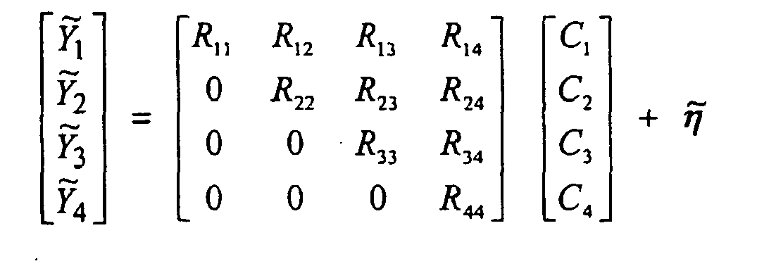
- As can be seen from the above Ỹ 4, is dependent only upon the matrix element R44. Thus, using the above arrangement it is possible to determine the most probable symbol, Sp, by enumerating only through, in the case of 16QAM, the sixteen possibilities for the value of C4. Whilst this is theoretically possible it would only be acceptable when the signal to noise ratio is very high. This is because if the mean value of a specific channel gain, in this case represented by R44, is small the effect of noise in disrupting the channel will be significant.
- It is usual to enumerate through the possible symbols over two channels, for example Ỹ 3 and Ỹ 4, in order to ensure that there is sufficient diversity within the enumerated channels so as to reduce the possibility of all three channel gains enumerated being small enough to be affected by noise. This arrangement reduces the complexity of determining transmitted symbols as, in the example discussed above, C1 and C2 are not required to determine C3 and C4.
- Referring now to
Figure 4a , in the example shown below there are assumed to be four transmit antennas, m, and four receive antennas, n, and anenumeration constraint 401, Ec, of two, i.e. only two symbols are considered for determination at any one time. - The conditional symbol probability including Gaussian noise, is given by:

- Now C is limited to C̃ = [C 3,C 4], as shown in
Figure 4a , the upper right-hand side of the matrix R contains the channel information values, represented assquares 402 inFigures 4a and the lower left-hand side represents null, zero 404, values of the matrix. - The symbol with the highest conditional probability is selected by the
symbol probability processor 224 as an estimated transmitted symbol transmitted from transmit antenna 4 and is given by:
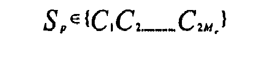
- In effect the joint probability calculation is simplified to :
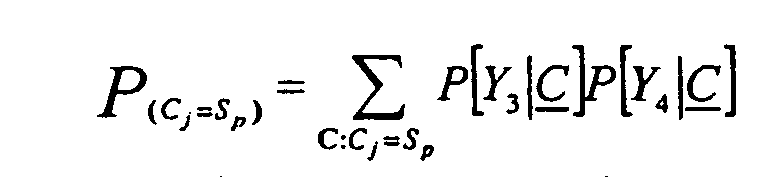

- Once C4 is determined as Sn this value can be fixed for all subsequent calculations as this merely affects the mean value of subsequent calculations:

- In an alternative computational scheme the fourth column of R is multiplied by Sn and subtracted from Ỹ thereby removing the effect of the previously determined from Ỹ .
- The effect of fixing C4 = Sn is shown in
Figure 4b wherein the marginal, conditional probability of any given symbol being transmitted from transmitter 3 is then calculated according to:
- As can be seen this conditional symbol probability calculation takes into account the previous symbol estimate made for Ĉ 4 and transmit and receive antennas 2 and 3 are considered for this calculation. The third term in the numerator cancels out the interference from transmit antenna 4, shown in
Figure 4b as asolid square 406. - A soft decision is now made for the symbol transmitted from transmit antenna 3 based upon the conditional probability of the most likely symbol to have been transmitted, Ĉj where j = 3, in a similar manner as that for the symbol transmitted from antenna 4 as described hereinbefore.
- Referring now to
Figure 4c conditional probabilities of the symbols transmitted by transmit antennas 1 and 2 to receive antennas 1 and 2 are now calculated
- The vector C̃=[C1,C2] is used to represent these conditional probabilities. The third term in the numerator cancels out the interference effects from antennas 3 and 4, shown in
Figure 4c assolid squares 406. - Again the transmitted symbols are estimated as being the symbol with the largest calculated marginal, conditional probability.
- The estimated symbols probabilities are converted to conditional bit probabilities at the symbol to bit
LLR convertor 225 through the following:
b3b2b1b0 P(C1) = P(0000) P(C2) = P(0001) P(C3) = P(0010) P(C4) = P(0011) P(C5) = P(0100) P(C6) = P(0101) P(C7) = P(0110) P(C8) = P(0111) P(C9) = P(1000) P(C10) = P(1001) P(C11) = P(1010) P(C12) = P(1011) P(C13) = P(1100) P(C14) = P(1101) P(C15) = P(1110) P(C16) = P(1111) - Thus


- Thus, bit level log likelihood ratios (LLR's) can be given by the natural logarithm:

- The bit level LLR's are fed into the parallel
serial converter 226 where they are converted into a single stream and are then passed to thedeinterleaver 228 which removes the effect of theinterleaver 206 at the transmitter. - The
decoder 230 maps iteratively decodes the stream of bit level LLR's as a soft output by use of a soft input soft output (SISO) algorithm, such algorithms include Maximum-A-Posteriori (MAP) or Low Density Parity Check (LDPC) algorithms. - Optionally, information obtained from the
decoder 230 at each iteration is fed back into the conditional probability calculations, typically this is symbol probability information. This information is treated as a-priori information which increases the accuracy of the information obtained according to:
- After a number of iterations, as few as ten have been shown to yield improvements in performance over prior art systems, final, hard, definitive, bit decisions are based upon the soft output values from the
decoder 230. - The method detailed hereinbefore estimates which symbol is most likely to have been transmitted using the Maximum-A-Posteriori (MAP) criteria in which:

- Referring now to
Figure 5 , a method of signal processing for a MIMO system comprises defining a QR decomposition of a channel gain matrix and setting an enumeration constraint upon the matrix (Step 500). Conditional symbol probabilities are calculated by enumerating across the desired block of the R matrix, using the enumeration constraint (Step 502). The effect of the symbol having the highest conditional symbol probability within the desired block of the R matrix is cancelled out (Step 504) and the R matrix is traversed with the cancellation process being repeated for each enumeration block (Step 506). - The apparatus and method described hereinbefore reduce the computational complexity of symbol determination by trading diversity upon receive against computational complexity.
- Using the MAP criterion to form decisions as in this approach gives a retained diversity order in symbol estimation that is given by the enumeration constraint Ec.

- The constraint Ec establishes smaller areas for symbol enumeration instead of using the whole channel matrix. Larger areas lead to a larger list of possible symbol candidates. Computational complexity is maintained within areas of equal size as the matrix is traversed. Enumeration are still related to the modulation mode utilised and is given by:

- The approach provides a flexible LLR computation, which is not restricted to the number of transmit antennas used in the MIMO architecture but upon a predefined subset of the transmit antennas at the receiver. The use of feedback within the computational scheme results in an improved computational scheme in which detection and decoding are not disjointed. This is of importance as any improvement in detection yields an improvement in decoding results and vice-versa.
Claims (23)
- A signal processing apparatus (204) comprising a plurality of receiving means (214a-d) arranged to receive a composite signal indicative of a plurality of symbols transmitted, simultaneously, from a plurality of remote transmission means (212a-d), and processing means (218) arranged to iteratively decode each most probable symbol contained in said composite signal, characterised in that the processing means is arranged to perform (221) a QR decomposition upon a channel gain matrix wherein decoding is performed within a constrained enumeration formalism and wherein the enumeration constraint (401) is a number of entries in an R matrix over which probable symbols are enumerated.
- Apparatus according to any preceding claim in which the enumeration constraint (401) is of constant dimension.
- Apparatus according to any preceding claim in which the enumeration constraint (401) involves considering for determination only two symbols at a time.
- Apparatus according to, any preceding claim wherein the processing means is arranged to define the enumeration constraint for use in the constrained enumeration formalism.
- Apparatus according to any preceding claim wherein the processing means is arranged to determine (214) the most probable symbol by enumerating across all symbol conditional probabilities for each possible symbol.
- Apparatus according to Claim 5 wherein the processing means is arranged to convert (225) symbol conditional probability to a bit level logarithmic likelihood ratio (LLR).
- Apparatus according to any preceding claim including a parallel to serial conversion means (226) arranged to convert parallel, bit level, LLR's into a single stream of LLR's.
- Apparatus according to Claim 7 including a deinterleaving means (228) arranged to deinterleave, bit level, LLR's from the single stream of LLR's.
- Apparatus according to any preceding claim including decoding means (230) arranged to apply iterative soft input soft output (SISO) decoding to single bit LLR's to determine a symbol.
- Apparatus according to Claim 9 wherein the decoding means (230) is arranged to pass a symbol probability to the processor for inclusion in an iterative enumeration step.
- Apparatus according to either of Claims 9 or 10 including a hard decision unit that is arranged to determine a symbol based upon a soft output from the decoding means.
- A method of signal processing for a MIMO system comprising the steps of:i) receiving (214a-d) a composite signal indicative of a plurality of symbols;ii) performing (221) a QR decomposition upon a channel gain matrix for the composite signal;iii) defining an enumeration constraint (401) as a number of entries in an R matrix over which probable symbols are enumerated;iv) calculating possible conditional probabilities for one of the plurality of symbols contained within the composite signal, using the enumeration constraint; andv) iterating step iv), incorporating a most probable symbol for the one symbol determined in the previous iteration of step iv) in the conditional probability calculation operation (225).
- A method according to Claim 12 including setting the enumeration constraint to encompass a sub-set of possible transmit antennas (210a-d).
- A method according to either of Claims 12 or 13 including defining the enumeration constraint as a number of elements (401) within an R matrix.
- A method according to any one of Claims 12 to 14 including calculating a symbol conditional probability in order to determine the most probable symbol received over a given transmission channel.
- A method according to Claim 15 including converting (225) the symbol conditional probability to a bit level logarithm likelihood ratio (LLR).
- A method according to any one of claims 12 to 16 to including converting (225) a plurality of parallel streams of bit level LLR's to a serial stream of bit level LLR's.
- A method according to Claim 17 including deinterleaving (228) bit level LLR's from the serial stream of bit level LLR's.
- A method according to any one of Claims 16 to 18 including decoding (230) the single bit LLR's.
- A method according to any one of Claims 12 to 19 including making a hard determination of a received symbol based upon a soft output from the decoding operation.
- A method according to any one of claims 12-20 wherein:i) the composite signal indicative of a plurality of symbols has spatial diversity from each of a set of n receiver elements;ii) the channel gain matrix is an n by m matrix constructed from values indicative of channel gains between each transmit and receive element;iii) QR decomposition upon the channel matrix forms an upper triangular R matrix and a unitary Q matrix;iv) the enumeration constraint is a constrained data sub-set of the triangular R matrix; and
wherein the method further comprises:v) making a hard decision about which possible symbol is the most probable symbol to have been transmitted so as to reduce the number of enumerations required to carry out a further probability calculation. - The method of Claim 21 including using sub-optimally determined symbol values to generate final definite symbol values.
- A computer readable medium having therein instructions for causing a processing unit to execute the method of any one of Claims 12 to 22.
Applications Claiming Priority (3)
| Application Number | Priority Date | Filing Date | Title |
|---|---|---|---|
| GB0307471 | 2003-04-01 | ||
| GBGB0307471.3A GB0307471D0 (en) | 2003-04-01 | 2003-04-01 | Signal Processing apparatus and method |
| PCT/GB2004/001386 WO2004088908A1 (en) | 2003-04-01 | 2004-03-31 | Signal processing apparatus and method |
Publications (2)
| Publication Number | Publication Date |
|---|---|
| EP1609265A1 EP1609265A1 (en) | 2005-12-28 |
| EP1609265B1 true EP1609265B1 (en) | 2010-06-09 |
Family
ID=9955934
Family Applications (1)
| Application Number | Title | Priority Date | Filing Date |
|---|---|---|---|
| EP04724633A Expired - Lifetime EP1609265B1 (en) | 2003-04-01 | 2004-03-31 | Signal processing apparatus and method |
Country Status (7)
| Country | Link |
|---|---|
| US (1) | US7782981B2 (en) |
| EP (1) | EP1609265B1 (en) |
| JP (1) | JP4505673B2 (en) |
| AT (1) | ATE471003T1 (en) |
| DE (1) | DE602004027610D1 (en) |
| GB (1) | GB0307471D0 (en) |
| WO (1) | WO2004088908A1 (en) |
Cited By (1)
| Publication number | Priority date | Publication date | Assignee | Title |
|---|---|---|---|---|
| CN110212924A (en) * | 2019-07-05 | 2019-09-06 | 中国人民解放军火箭军工程大学 | A kind of LT code decoding method and system |
Families Citing this family (9)
| Publication number | Priority date | Publication date | Assignee | Title |
|---|---|---|---|---|
| GB2420951B (en) * | 2004-12-02 | 2007-06-06 | Toshiba Res Europ Ltd | Decoder for a multiplexed transmission system |
| JP4476117B2 (en) * | 2004-12-28 | 2010-06-09 | 富士通株式会社 | Wireless communication device |
| US8971461B2 (en) * | 2005-06-01 | 2015-03-03 | Qualcomm Incorporated | CQI and rank prediction for list sphere decoding and ML MIMO receivers |
| US8369449B2 (en) * | 2005-09-20 | 2013-02-05 | Koninklijke Philips Electronics N.V. | Method and system of diversity transmission of data employing M-point QAM modulation |
| KR100965728B1 (en) * | 2007-06-12 | 2010-06-24 | 삼성전자주식회사 | Signal detection device and method using maximum likelihood method |
| KR100912510B1 (en) * | 2007-12-11 | 2009-08-17 | 한국전자통신연구원 | Transmission symbol detection method in multi-antenna system |
| US8744015B2 (en) * | 2010-06-04 | 2014-06-03 | Blackberry Limited | Message decoding for discretized signal transmissions |
| US20120069833A1 (en) * | 2010-09-16 | 2012-03-22 | Molnar Karl J | Channel state information reporting for a successively decoded, precoded multi-antenna transmission |
| US10374682B2 (en) * | 2014-04-17 | 2019-08-06 | Lg Electronics Inc. | Method and device for removing self-interference in wireless access system supporting full duplex radio scheme |
Family Cites Families (9)
| Publication number | Priority date | Publication date | Assignee | Title |
|---|---|---|---|---|
| GB8318333D0 (en) * | 1983-07-06 | 1983-08-10 | Secr Defence | Systolic array |
| EP0131416B1 (en) * | 1983-07-06 | 1990-06-13 | The Secretary of State for Defence in Her Britannic Majesty's Government of the United Kingdom of Great Britain and | Constraint application processor |
| US6317466B1 (en) * | 1998-04-15 | 2001-11-13 | Lucent Technologies Inc. | Wireless communications system having a space-time architecture employing multi-element antennas at both the transmitter and receiver |
| US6473467B1 (en) * | 2000-03-22 | 2002-10-29 | Qualcomm Incorporated | Method and apparatus for measuring reporting channel state information in a high efficiency, high performance communications system |
| US6785341B2 (en) | 2001-05-11 | 2004-08-31 | Qualcomm Incorporated | Method and apparatus for processing data in a multiple-input multiple-output (MIMO) communication system utilizing channel state information |
| GB2375464B (en) | 2001-05-11 | 2003-05-28 | Motorola Inc | Method and device for multi-user detection in CDMA channels |
| US7154936B2 (en) | 2001-12-03 | 2006-12-26 | Qualcomm, Incorporated | Iterative detection and decoding for a MIMO-OFDM system |
| US7289585B2 (en) * | 2004-01-12 | 2007-10-30 | Intel Corporation | Multicarrier receivers and methods for separating transmitted signals in a multiple antenna system |
| US7649955B2 (en) * | 2006-03-24 | 2010-01-19 | Intel Corporation | MIMO receiver and method for beamforming using CORDIC operations |
-
2003
- 2003-04-01 GB GBGB0307471.3A patent/GB0307471D0/en not_active Ceased
-
2004
- 2004-03-31 JP JP2006506063A patent/JP4505673B2/en not_active Expired - Fee Related
- 2004-03-31 AT AT04724633T patent/ATE471003T1/en not_active IP Right Cessation
- 2004-03-31 WO PCT/GB2004/001386 patent/WO2004088908A1/en not_active Ceased
- 2004-03-31 US US10/551,628 patent/US7782981B2/en active Active
- 2004-03-31 DE DE602004027610T patent/DE602004027610D1/en not_active Expired - Lifetime
- 2004-03-31 EP EP04724633A patent/EP1609265B1/en not_active Expired - Lifetime
Cited By (1)
| Publication number | Priority date | Publication date | Assignee | Title |
|---|---|---|---|---|
| CN110212924A (en) * | 2019-07-05 | 2019-09-06 | 中国人民解放军火箭军工程大学 | A kind of LT code decoding method and system |
Also Published As
| Publication number | Publication date |
|---|---|
| ATE471003T1 (en) | 2010-06-15 |
| JP2006522521A (en) | 2006-09-28 |
| EP1609265A1 (en) | 2005-12-28 |
| US20080049862A1 (en) | 2008-02-28 |
| DE602004027610D1 (en) | 2010-07-22 |
| JP4505673B2 (en) | 2010-07-21 |
| US7782981B2 (en) | 2010-08-24 |
| GB0307471D0 (en) | 2003-05-07 |
| WO2004088908A1 (en) | 2004-10-14 |
Similar Documents
| Publication | Publication Date | Title |
|---|---|---|
| RU2414062C2 (en) | Low-complexity detection and decoding for receiver in communication system | |
| US7986752B2 (en) | Parallel soft spherical MIMO receiver and decoding method | |
| US6898248B1 (en) | System employing threaded space-time architecture for transporting symbols and receivers for multi-user detection and decoding of symbols | |
| JP4803384B2 (en) | Spatial multiple signal detection method and spatio-temporal iterative decoder using the same | |
| US10211952B2 (en) | Scheme for communication using integer-forcing scheme in wireless communication system | |
| US8045604B2 (en) | Estimation of log-likelihood using constrained markov-chain monte carlo simulation | |
| US20100316151A1 (en) | Receiving apparatus, receiving method and communication system | |
| JP2009527174A (en) | Apparatus, method and computer program for providing MIMO receiver | |
| US8488721B2 (en) | Adaptive QRD-M algorithm based signal detecting method by using constellation set grouping in spatial multiplexing multiple-input multiple-output system | |
| JP2009207117A (en) | Method for generating soft output with respect to reception signal in mimo receiver and transceiver including transmitter and receiver | |
| JP2004343702A (en) | MIMO telecommunications system, transmission symbol decoding method and transmission symbol decoding apparatus in this system | |
| US20140169412A1 (en) | System and Method for Low Density Spreading Modulation Detection | |
| Zheng et al. | LDPC-coded MIMO systems with unknown block fading channels: soft MIMO detector design, channel estimation, and code optimization | |
| US20070198719A1 (en) | Method and system for minimum mean squared error soft interference cancellation (MMSE-SIC) Based suboptimal maximum likelihood (ML) detection for multiple input multiple output (MIMO) wireless system | |
| US8139669B2 (en) | Space domain filter detecting method in a multi-antenna wireless communication system | |
| US7782981B2 (en) | Signal processing apparatus and method | |
| KR100651036B1 (en) | Iterative Decoding Receiving Device and Method for Reducing Partial Decoding-based Complexity in Spatial Multiplexing System | |
| US20060171483A1 (en) | Decoder for a multiplexed transmission system | |
| KR100690873B1 (en) | Decoding Device and Method of MIO System | |
| RU2523190C1 (en) | Method for iterative detection and decoding of signal in communication systems with mimo channel | |
| JP6180333B2 (en) | Method for decoding a signal in a radio frequency receiver | |
| Jalali et al. | A joint detection and decoding receiver design for polar coded MIMO wireless transmissions | |
| WO2006051156A1 (en) | Low density parity check codes for mimo systems | |
| CN101026435A (en) | Low-complexity maximum likelihood detecting method and device for communication system | |
| US8081577B2 (en) | Method of calculating soft value and method of detecting transmission signal |
Legal Events
| Date | Code | Title | Description |
|---|---|---|---|
| PUAI | Public reference made under article 153(3) epc to a published international application that has entered the european phase |
Free format text: ORIGINAL CODE: 0009012 |
|
| 17P | Request for examination filed |
Effective date: 20051001 |
|
| AK | Designated contracting states |
Kind code of ref document: A1 Designated state(s): AT BE BG CH CY CZ DE DK EE ES FI FR GB GR HU IE IT LI LU MC NL PL PT RO SE SI SK TR |
|
| AX | Request for extension of the european patent |
Extension state: AL LT LV MK |
|
| DAX | Request for extension of the european patent (deleted) | ||
| RAP1 | Party data changed (applicant data changed or rights of an application transferred) |
Owner name: F. POSZAT HU, LLC |
|
| RAP1 | Party data changed (applicant data changed or rights of an application transferred) |
Owner name: VOCALCOMM GROUP, LLC |
|
| GRAP | Despatch of communication of intention to grant a patent |
Free format text: ORIGINAL CODE: EPIDOSNIGR1 |
|
| GRAS | Grant fee paid |
Free format text: ORIGINAL CODE: EPIDOSNIGR3 |
|
| GRAA | (expected) grant |
Free format text: ORIGINAL CODE: 0009210 |
|
| AK | Designated contracting states |
Kind code of ref document: B1 Designated state(s): AT BE BG CH CY CZ DE DK EE ES FI FR GB GR HU IE IT LI LU MC NL PL PT RO SE SI SK TR |
|
| REG | Reference to a national code |
Ref country code: CH Ref legal event code: EP |
|
| REG | Reference to a national code |
Ref country code: IE Ref legal event code: FG4D |
|
| REF | Corresponds to: |
Ref document number: 602004027610 Country of ref document: DE Date of ref document: 20100722 Kind code of ref document: P |
|
| REG | Reference to a national code |
Ref country code: NL Ref legal event code: VDEP Effective date: 20100609 |
|
| PG25 | Lapsed in a contracting state [announced via postgrant information from national office to epo] |
Ref country code: SE Free format text: LAPSE BECAUSE OF FAILURE TO SUBMIT A TRANSLATION OF THE DESCRIPTION OR TO PAY THE FEE WITHIN THE PRESCRIBED TIME-LIMIT Effective date: 20100609 |
|
| PG25 | Lapsed in a contracting state [announced via postgrant information from national office to epo] |
Ref country code: SI Free format text: LAPSE BECAUSE OF FAILURE TO SUBMIT A TRANSLATION OF THE DESCRIPTION OR TO PAY THE FEE WITHIN THE PRESCRIBED TIME-LIMIT Effective date: 20100609 Ref country code: AT Free format text: LAPSE BECAUSE OF FAILURE TO SUBMIT A TRANSLATION OF THE DESCRIPTION OR TO PAY THE FEE WITHIN THE PRESCRIBED TIME-LIMIT Effective date: 20100609 Ref country code: FI Free format text: LAPSE BECAUSE OF FAILURE TO SUBMIT A TRANSLATION OF THE DESCRIPTION OR TO PAY THE FEE WITHIN THE PRESCRIBED TIME-LIMIT Effective date: 20100609 |
|
| PG25 | Lapsed in a contracting state [announced via postgrant information from national office to epo] |
Ref country code: CY Free format text: LAPSE BECAUSE OF FAILURE TO SUBMIT A TRANSLATION OF THE DESCRIPTION OR TO PAY THE FEE WITHIN THE PRESCRIBED TIME-LIMIT Effective date: 20100609 Ref country code: PL Free format text: LAPSE BECAUSE OF FAILURE TO SUBMIT A TRANSLATION OF THE DESCRIPTION OR TO PAY THE FEE WITHIN THE PRESCRIBED TIME-LIMIT Effective date: 20100609 Ref country code: GR Free format text: LAPSE BECAUSE OF FAILURE TO SUBMIT A TRANSLATION OF THE DESCRIPTION OR TO PAY THE FEE WITHIN THE PRESCRIBED TIME-LIMIT Effective date: 20100910 |
|
| PG25 | Lapsed in a contracting state [announced via postgrant information from national office to epo] |
Ref country code: NL Free format text: LAPSE BECAUSE OF FAILURE TO SUBMIT A TRANSLATION OF THE DESCRIPTION OR TO PAY THE FEE WITHIN THE PRESCRIBED TIME-LIMIT Effective date: 20100609 Ref country code: EE Free format text: LAPSE BECAUSE OF FAILURE TO SUBMIT A TRANSLATION OF THE DESCRIPTION OR TO PAY THE FEE WITHIN THE PRESCRIBED TIME-LIMIT Effective date: 20100609 |
|
| PG25 | Lapsed in a contracting state [announced via postgrant information from national office to epo] |
Ref country code: PT Free format text: LAPSE BECAUSE OF FAILURE TO SUBMIT A TRANSLATION OF THE DESCRIPTION OR TO PAY THE FEE WITHIN THE PRESCRIBED TIME-LIMIT Effective date: 20101011 Ref country code: SK Free format text: LAPSE BECAUSE OF FAILURE TO SUBMIT A TRANSLATION OF THE DESCRIPTION OR TO PAY THE FEE WITHIN THE PRESCRIBED TIME-LIMIT Effective date: 20100609 Ref country code: BE Free format text: LAPSE BECAUSE OF FAILURE TO SUBMIT A TRANSLATION OF THE DESCRIPTION OR TO PAY THE FEE WITHIN THE PRESCRIBED TIME-LIMIT Effective date: 20100609 Ref country code: CZ Free format text: LAPSE BECAUSE OF FAILURE TO SUBMIT A TRANSLATION OF THE DESCRIPTION OR TO PAY THE FEE WITHIN THE PRESCRIBED TIME-LIMIT Effective date: 20100609 Ref country code: RO Free format text: LAPSE BECAUSE OF FAILURE TO SUBMIT A TRANSLATION OF THE DESCRIPTION OR TO PAY THE FEE WITHIN THE PRESCRIBED TIME-LIMIT Effective date: 20100609 |
|
| PG25 | Lapsed in a contracting state [announced via postgrant information from national office to epo] |
Ref country code: IT Free format text: LAPSE BECAUSE OF FAILURE TO SUBMIT A TRANSLATION OF THE DESCRIPTION OR TO PAY THE FEE WITHIN THE PRESCRIBED TIME-LIMIT Effective date: 20100609 |
|
| PLBE | No opposition filed within time limit |
Free format text: ORIGINAL CODE: 0009261 |
|
| STAA | Information on the status of an ep patent application or granted ep patent |
Free format text: STATUS: NO OPPOSITION FILED WITHIN TIME LIMIT |
|
| PG25 | Lapsed in a contracting state [announced via postgrant information from national office to epo] |
Ref country code: DK Free format text: LAPSE BECAUSE OF FAILURE TO SUBMIT A TRANSLATION OF THE DESCRIPTION OR TO PAY THE FEE WITHIN THE PRESCRIBED TIME-LIMIT Effective date: 20100609 |
|
| 26N | No opposition filed |
Effective date: 20110310 |
|
| REG | Reference to a national code |
Ref country code: DE Ref legal event code: R097 Ref document number: 602004027610 Country of ref document: DE Effective date: 20110309 |
|
| PG25 | Lapsed in a contracting state [announced via postgrant information from national office to epo] |
Ref country code: MC Free format text: LAPSE BECAUSE OF NON-PAYMENT OF DUE FEES Effective date: 20110331 |
|
| REG | Reference to a national code |
Ref country code: CH Ref legal event code: PL |
|
| REG | Reference to a national code |
Ref country code: IE Ref legal event code: MM4A |
|
| PG25 | Lapsed in a contracting state [announced via postgrant information from national office to epo] |
Ref country code: LI Free format text: LAPSE BECAUSE OF NON-PAYMENT OF DUE FEES Effective date: 20110331 Ref country code: CH Free format text: LAPSE BECAUSE OF NON-PAYMENT OF DUE FEES Effective date: 20110331 Ref country code: IE Free format text: LAPSE BECAUSE OF NON-PAYMENT OF DUE FEES Effective date: 20110331 |
|
| PGFP | Annual fee paid to national office [announced via postgrant information from national office to epo] |
Ref country code: FR Payment date: 20120328 Year of fee payment: 9 |
|
| PGFP | Annual fee paid to national office [announced via postgrant information from national office to epo] |
Ref country code: GB Payment date: 20120227 Year of fee payment: 9 |
|
| PGFP | Annual fee paid to national office [announced via postgrant information from national office to epo] |
Ref country code: DE Payment date: 20120330 Year of fee payment: 9 |
|
| PG25 | Lapsed in a contracting state [announced via postgrant information from national office to epo] |
Ref country code: LU Free format text: LAPSE BECAUSE OF NON-PAYMENT OF DUE FEES Effective date: 20110331 |
|
| PG25 | Lapsed in a contracting state [announced via postgrant information from national office to epo] |
Ref country code: TR Free format text: LAPSE BECAUSE OF FAILURE TO SUBMIT A TRANSLATION OF THE DESCRIPTION OR TO PAY THE FEE WITHIN THE PRESCRIBED TIME-LIMIT Effective date: 20100609 Ref country code: BG Free format text: LAPSE BECAUSE OF FAILURE TO SUBMIT A TRANSLATION OF THE DESCRIPTION OR TO PAY THE FEE WITHIN THE PRESCRIBED TIME-LIMIT Effective date: 20100909 |
|
| PG25 | Lapsed in a contracting state [announced via postgrant information from national office to epo] |
Ref country code: HU Free format text: LAPSE BECAUSE OF FAILURE TO SUBMIT A TRANSLATION OF THE DESCRIPTION OR TO PAY THE FEE WITHIN THE PRESCRIBED TIME-LIMIT Effective date: 20100609 Ref country code: ES Free format text: LAPSE BECAUSE OF FAILURE TO SUBMIT A TRANSLATION OF THE DESCRIPTION OR TO PAY THE FEE WITHIN THE PRESCRIBED TIME-LIMIT Effective date: 20100920 |
|
| GBPC | Gb: european patent ceased through non-payment of renewal fee |
Effective date: 20130331 |
|
| REG | Reference to a national code |
Ref country code: FR Ref legal event code: ST Effective date: 20131129 |
|
| REG | Reference to a national code |
Ref country code: DE Ref legal event code: R119 Ref document number: 602004027610 Country of ref document: DE Effective date: 20131001 |
|
| PG25 | Lapsed in a contracting state [announced via postgrant information from national office to epo] |
Ref country code: FR Free format text: LAPSE BECAUSE OF NON-PAYMENT OF DUE FEES Effective date: 20130402 Ref country code: DE Free format text: LAPSE BECAUSE OF NON-PAYMENT OF DUE FEES Effective date: 20131001 Ref country code: GB Free format text: LAPSE BECAUSE OF NON-PAYMENT OF DUE FEES Effective date: 20130331 |