EP1608948B1 - Automatic thermal desorption apparatus - Google Patents
Automatic thermal desorption apparatus Download PDFInfo
- Publication number
- EP1608948B1 EP1608948B1 EP03812218.0A EP03812218A EP1608948B1 EP 1608948 B1 EP1608948 B1 EP 1608948B1 EP 03812218 A EP03812218 A EP 03812218A EP 1608948 B1 EP1608948 B1 EP 1608948B1
- Authority
- EP
- European Patent Office
- Prior art keywords
- sample
- tube
- released
- collecting
- sampling
- Prior art date
- Legal status (The legal status is an assumption and is not a legal conclusion. Google has not performed a legal analysis and makes no representation as to the accuracy of the status listed.)
- Expired - Lifetime
Links
- 238000003795 desorption Methods 0.000 title description 5
- 238000005070 sampling Methods 0.000 claims description 32
- 239000002594 sorbent Substances 0.000 claims description 14
- 238000004458 analytical method Methods 0.000 claims description 9
- 238000001179 sorption measurement Methods 0.000 description 5
- 238000001816 cooling Methods 0.000 description 4
- 239000011261 inert gas Substances 0.000 description 4
- 238000000034 method Methods 0.000 description 4
- 230000001419 dependent effect Effects 0.000 description 1
- 238000010438 heat treatment Methods 0.000 description 1
- 230000004048 modification Effects 0.000 description 1
- 238000012986 modification Methods 0.000 description 1
- 239000000126 substance Substances 0.000 description 1
- 108010063955 thrombin receptor peptide (42-47) Proteins 0.000 description 1
Images

Classifications
-
- G—PHYSICS
- G01—MEASURING; TESTING
- G01N—INVESTIGATING OR ANALYSING MATERIALS BY DETERMINING THEIR CHEMICAL OR PHYSICAL PROPERTIES
- G01N1/00—Sampling; Preparing specimens for investigation
- G01N1/28—Preparing specimens for investigation including physical details of (bio-)chemical methods covered elsewhere, e.g. G01N33/50, C12Q
- G01N1/40—Concentrating samples
- G01N1/405—Concentrating samples by adsorption or absorption
-
- G—PHYSICS
- G01—MEASURING; TESTING
- G01N—INVESTIGATING OR ANALYSING MATERIALS BY DETERMINING THEIR CHEMICAL OR PHYSICAL PROPERTIES
- G01N30/00—Investigating or analysing materials by separation into components using adsorption, absorption or similar phenomena or using ion-exchange, e.g. chromatography or field flow fractionation
-
- G—PHYSICS
- G01—MEASURING; TESTING
- G01N—INVESTIGATING OR ANALYSING MATERIALS BY DETERMINING THEIR CHEMICAL OR PHYSICAL PROPERTIES
- G01N1/00—Sampling; Preparing specimens for investigation
- G01N1/02—Devices for withdrawing samples
- G01N1/22—Devices for withdrawing samples in the gaseous state
- G01N1/2202—Devices for withdrawing samples in the gaseous state involving separation of sample components during sampling
- G01N1/2214—Devices for withdrawing samples in the gaseous state involving separation of sample components during sampling by sorption
-
- G—PHYSICS
- G01—MEASURING; TESTING
- G01N—INVESTIGATING OR ANALYSING MATERIALS BY DETERMINING THEIR CHEMICAL OR PHYSICAL PROPERTIES
- G01N30/00—Investigating or analysing materials by separation into components using adsorption, absorption or similar phenomena or using ion-exchange, e.g. chromatography or field flow fractionation
- G01N2030/0075—Separation due to differential desorption
- G01N2030/008—Thermal desorption
-
- G—PHYSICS
- G01—MEASURING; TESTING
- G01N—INVESTIGATING OR ANALYSING MATERIALS BY DETERMINING THEIR CHEMICAL OR PHYSICAL PROPERTIES
- G01N30/00—Investigating or analysing materials by separation into components using adsorption, absorption or similar phenomena or using ion-exchange, e.g. chromatography or field flow fractionation
- G01N30/02—Column chromatography
- G01N30/04—Preparation or injection of sample to be analysed
- G01N30/06—Preparation
- G01N30/12—Preparation by evaporation
- G01N2030/121—Preparation by evaporation cooling; cold traps
-
- G—PHYSICS
- G01—MEASURING; TESTING
- G01N—INVESTIGATING OR ANALYSING MATERIALS BY DETERMINING THEIR CHEMICAL OR PHYSICAL PROPERTIES
- G01N30/00—Investigating or analysing materials by separation into components using adsorption, absorption or similar phenomena or using ion-exchange, e.g. chromatography or field flow fractionation
- G01N30/02—Column chromatography
- G01N30/04—Preparation or injection of sample to be analysed
- G01N30/06—Preparation
- G01N30/12—Preparation by evaporation
- G01N2030/121—Preparation by evaporation cooling; cold traps
- G01N2030/123—Preparation by evaporation cooling; cold traps using more than one trap
Definitions
- the present invention relates to an analytical apparatus and, more particularly, to an automatic thermal desorption apparatus, and a method for carrying out an automated analytical procedure.
- thermo desorption apparatus comprising an autosampler for automatically selecting one of a plurality of sampling tubes stored therein, heating the tube to desorb a sample from a sorbent material contained in the tube and then providing a flow of inert gas through the tube to drive the sample therefrom.
- Known apparatus further comprise means for analysing a first portion of the sample driven from each sampling tube and for collecting a second portion of the sample in a respective collecting tube, for subsequent analysis.
- a further drawback of such known apparatus is that automatic storage means must be provided for storing the collecting tubes in which respective portions of the samples released from each of the sampling tubes are collected, independent of the autosampler in which the sampling tubes are stored.
- Document EP 1 004 871 discloses a sample tube where a sample is released by thermal desorption from a sorbent material therein, a source of inert gas , a trap tube with sorbent material, a secondary sampling tube. Document EP 1 004 871 further disclosed that the released sample is split in two, the second sample portion being transferred to the secondary sampling tube. In a further step, the trap tube is heated and volatile substances carried to the sensor to be analysed.
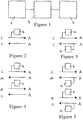
- FIG. 1 a first embodiment of analytical apparatus in accordance with the present invention is schematically illustrated, the apparatus comprising an autosampler 2, within which a plurality of sorbent tubes are stored (sampling tubes), analysis means 4 and a further sorbent tube (collecting tube) or trap 6.
- the autosampler may instead be replaced by a single sampling tube.
- sampling tubes are automatically selected, in turn, from those stored in the autosampler.
- Each tube (L) is first heated to desorb a sample from a sorbent material contained therein and the desorbed sample driven from the tube by a flow of inert gas therethrough.
- a first portion of the sample driven from the sampling tube (L) is analysed by the analysing means 4 and a second portion passed through the collecting tube (A), within which it is adsorbed by the sorbent material therein or contained in a trap.
- the collecting tube (A) is then heated to desorb the sample from the sorbent material therein and is driven out of the tube by a reversed flow of inert gas.
- the entire sample thus released from the collecting tube (A) may then be passed through the sampling tube (L), within which it is re-adsorbed for archiving or subsequent analysis ( Figure 2 ), or only a portion of the sample may be passed through the sampling tube (L) for re-adsorption, with a second portion of the sample being analysed by the analysing means 4 ( Figure 3 ).
- the apparatus preferably comprises means for cooling the sampling tube (L) to facilitate re-adsorption by the sorbent material contained therein.
- the apparatus preferably comprises means for cooling the collecting tube (A) to facilitate adsorption by the sorbent material contained therein.
- the whole ( Figure 4 ) or a portion ( Figure 5 ) of the sample released from the collecting (A) tube may be passed through a sorbent tube (M) other than the sampling tube (re-collecting tube), with which the sampling tube (L) is replaced in the autosampler.
- M sorbent tube
- each sampling tube (L,N) selected from the autosampler may be repeated for each sampling tube (L,N) selected from the autosampler, either using a single collecting tube (A) for collecting the second portion of the sample released from each sampling tube ( Figures 4 and 5 ) or using a respective collecting tube (A,B) for each sample, as illustrated schematically in Figures 6 and 7 , with each collecting tube being selected, in turn, from a plurality of collecting tubes stored in a second autosampler.
- the apparatus preferably comprises means for cooling the collecting tube (A) to facilitate adsorption by the sorbent material contained therein.
- the entire sample driven from each sampling tube may be collected in a collecting tube, a first portion of the sample subsequently released from the collecting tube being analysed by the analysing means 4, with a second portion of the sample being re-collected in the sampling tube or a re-collection tube.
- the apparatus preferably comprises means for cooling the collecting tube to facilitate adsorption by the sorbent material contained therein.
- the various apparatus thus described provide an efficient and labour saving means for the thermal desorption of a plurality of samples contained in respective sampling tubes, wherein a portion of the desorbed sample is to be collected for subsequent analysis.
Landscapes
- Physics & Mathematics (AREA)
- Health & Medical Sciences (AREA)
- Life Sciences & Earth Sciences (AREA)
- Chemical & Material Sciences (AREA)
- Analytical Chemistry (AREA)
- Biochemistry (AREA)
- General Health & Medical Sciences (AREA)
- General Physics & Mathematics (AREA)
- Immunology (AREA)
- Pathology (AREA)
- Sampling And Sample Adjustment (AREA)
Description
- The present invention relates to an analytical apparatus and, more particularly, to an automatic thermal desorption apparatus, and a method for carrying out an automated analytical procedure.
- It is known to provide a thermal desorption apparatus comprising an autosampler for automatically selecting one of a plurality of sampling tubes stored therein, heating the tube to desorb a sample from a sorbent material contained in the tube and then providing a flow of inert gas through the tube to drive the sample therefrom.
- Known apparatus further comprise means for analysing a first portion of the sample driven from each sampling tube and for collecting a second portion of the sample in a respective collecting tube, for subsequent analysis.
- However, a drawback of such known apparatus is that, following the analysis of samples released from a number of sampling tubes, their respective collecting tubes must be manually loaded into the autosampler for a subsequent analysis to be carried out.
- A further drawback of such known apparatus is that automatic storage means must be provided for storing the collecting tubes in which respective portions of the samples released from each of the sampling tubes are collected, independent of the autosampler in which the sampling tubes are stored.
- Document
EP 1 004 871 discloses a sample tube where a sample is released by thermal desorption from a sorbent material therein, a source of inert gas , a trap tube with sorbent material, a secondary sampling tube. DocumentEP 1 004 871 further disclosed that the released sample is split in two, the second sample portion being transferred to the secondary sampling tube. In a further step, the trap tube is heated and volatile substances carried to the sensor to be analysed. - We have now devised an arrangement which overcomes the limitations of known analytical apparatus.
- In accordance with the present invention, there is provided an analytical apparatus according to claim 1.
- Advantageous embodiments are defined in the dependent claims.
- Embodiments of the present invention will now be described by way of examples only and with reference to the accompanying drawings, of which:
-
FIGURE 1 is a schematic illustration of an embodiment of apparatus in accordance with the present invention; -
FIGURES 2 to 5 are schematic illustrations of respective modes of operation of the apparatus ofFigure 1 -
FIGURES 6 and 7 are schematic illustrations of respective modes of operation of a second embodiment of apparatus in accordance with the present invention. - Referring to
Figure 1 , a first embodiment of analytical apparatus in accordance with the present invention is schematically illustrated, the apparatus comprising anautosampler 2, within which a plurality of sorbent tubes are stored (sampling tubes), analysis means 4 and a further sorbent tube (collecting tube) ortrap 6. The autosampler may instead be replaced by a single sampling tube. - In a first mode of operation of the apparatus, illustrated in
Figures 2 and 3 , sampling tubes are automatically selected, in turn, from those stored in the autosampler. Each tube (L) is first heated to desorb a sample from a sorbent material contained therein and the desorbed sample driven from the tube by a flow of inert gas therethrough. - A first portion of the sample driven from the sampling tube (L) is analysed by the
analysing means 4 and a second portion passed through the collecting tube (A), within which it is adsorbed by the sorbent material therein or contained in a trap. - The collecting tube (A) is then heated to desorb the sample from the sorbent material therein and is driven out of the tube by a reversed flow of inert gas.
- The entire sample thus released from the collecting tube (A) may then be passed through the sampling tube (L), within which it is re-adsorbed for archiving or subsequent analysis (
Figure 2 ), or only a portion of the sample may be passed through the sampling tube (L) for re-adsorption, with a second portion of the sample being analysed by the analysing means 4 (Figure 3 ). - In the former case the apparatus preferably comprises means for cooling the sampling tube (L) to facilitate re-adsorption by the sorbent material contained therein. In both cases, the apparatus preferably comprises means for cooling the collecting tube (A) to facilitate adsorption by the sorbent material contained therein.
- In a first modification of the above process, illustrated schematically in
Figures 4 and 5 , the whole (Figure 4 ) or a portion (Figure 5 ) of the sample released from the collecting (A) tube may be passed through a sorbent tube (M) other than the sampling tube (re-collecting tube), with which the sampling tube (L) is replaced in the autosampler. - The same process may be repeated for each sampling tube (L,N) selected from the autosampler, either using a single collecting tube (A) for collecting the second portion of the sample released from each sampling tube (
Figures 4 and 5 ) or using a respective collecting tube (A,B) for each sample, as illustrated schematically inFigures 6 and 7 , with each collecting tube being selected, in turn, from a plurality of collecting tubes stored in a second autosampler. In the former case, the apparatus preferably comprises means for cooling the collecting tube (A) to facilitate adsorption by the sorbent material contained therein. - As a variation on the processes illustrated in
Figures 2, 4 , and6 , the entire sample driven from each sampling tube may be collected in a collecting tube, a first portion of the sample subsequently released from the collecting tube being analysed by theanalysing means 4, with a second portion of the sample being re-collected in the sampling tube or a re-collection tube. The apparatus preferably comprises means for cooling the collecting tube to facilitate adsorption by the sorbent material contained therein. - It would also remain in accordance with the present invention, in those embodiments in respect of which the use of only a single collecting tube has been described, for the collecting tube to be substituted with a trap.
- The various apparatus thus described provide an efficient and labour saving means for the thermal desorption of a plurality of samples contained in respective sampling tubes, wherein a portion of the desorbed sample is to be collected for subsequent analysis.
Claims (7)
- An analytical apparatus for automatically carrying out a plurality of steps, the apparatus comprising:a tube selector for automatically selecting a first sampling tube (L) from a plurality of sampling tubes stored within an autosampler;a release device for automatically releasing a sample from the first sampling tube (L) to provide a released sample;an analyser (4) for automatically analysing a first portion of the released sample; anda re-collection device;characterised in that the re-collection device is arranged to automatically collect a second portion of the released sample on a sorbent material contained either in:a) the first sampling tube (L); or inb) a collecting tube selected automatically from said plurality of sampling tubes with which the first sampling tube (L) is replaced by the collecting tube within the autosampler (2).
- An analytical apparatus according to claim 1 comprising a re-release device for automatically re-releasing said second portion of the released sample that has been collected by the re-collection device to provide a re-released portion of the sample for archiving or further analysis.
- An apparatus according to any preceding claim, further comprising means for automatically analysing the re-released sample.
- An analytical apparatus according to claim 3 which is arranged to provide a comparison of the results from each of the two analysis stages.
- An analytical apparatus according to claim 2 or 3 wherein a first portion of the re-released sample is analysed, a second portion of the re-released sample being re-collected, either in the first sampling tube (L) or in a collecting tube selected automatically from said plurality of sampling tubes, with which the first sampling tube (L) is replaced by the collecting tube within the autosampler.
- An analytical apparatus according to any preceding claim, arranged such that the sample released from the first sampling tube (L) is buffered, by collecting the sample in an intermediate tube or trap, prior to the steps of analysing the first portion of the released sample and collecting the second portion of the released sample.
- An analytical apparatus according to any of claims 1 to 6, wherein the second portion of the sample released from the sampling tube, or subsequently collected and re-released, is buffered by collecting the sample in an intermediate tube or trap, prior to its collection/re-collection.
Applications Claiming Priority (3)
| Application Number | Priority Date | Filing Date | Title |
|---|---|---|---|
| GB0228006A GB2395785B (en) | 2002-11-30 | 2002-11-30 | Analytical apparatus |
| GB0228006 | 2002-11-30 | ||
| PCT/GB2003/005242 WO2004051227A1 (en) | 2002-11-30 | 2003-12-01 | Automatic thermal desorption apparatus and method |
Publications (2)
| Publication Number | Publication Date |
|---|---|
| EP1608948A1 EP1608948A1 (en) | 2005-12-28 |
| EP1608948B1 true EP1608948B1 (en) | 2019-09-25 |
Family
ID=9948871
Family Applications (1)
| Application Number | Title | Priority Date | Filing Date |
|---|---|---|---|
| EP03812218.0A Expired - Lifetime EP1608948B1 (en) | 2002-11-30 | 2003-12-01 | Automatic thermal desorption apparatus |
Country Status (5)
| Country | Link |
|---|---|
| US (1) | US7373847B2 (en) |
| EP (1) | EP1608948B1 (en) |
| AU (1) | AU2003302700A1 (en) |
| GB (1) | GB2395785B (en) |
| WO (1) | WO2004051227A1 (en) |
Families Citing this family (2)
| Publication number | Priority date | Publication date | Assignee | Title |
|---|---|---|---|---|
| DE102013107101A1 (en) * | 2013-07-05 | 2015-01-08 | Netzsch-Gerätebau GmbH | PROCESS AND MAGAZINE FOR THE PROVISION, TRANSPORT, PROCESSING AND ARCHIVING OF THERMOANALYTIC SAMPLES |
| WO2015198272A1 (en) * | 2014-06-25 | 2015-12-30 | B.S. Ma'avarim Ltd | Apparatus for sampling chemical substances, and methods therefor |
Family Cites Families (15)
| Publication number | Priority date | Publication date | Assignee | Title |
|---|---|---|---|---|
| US4701306A (en) * | 1984-06-05 | 1987-10-20 | Canadian Patents & Development Ltd. | Concentrator for detection of amine vapors |
| US5014541A (en) * | 1988-02-22 | 1991-05-14 | Cms Research Corporation | Continuous air monitoring apparatus and method |
| US4976924A (en) * | 1988-04-22 | 1990-12-11 | Her Majesty The Queen In Right Of Canada, As Represented By The Minister Of National Defence | Automated thermal desorption unit |
| EP0459677A3 (en) * | 1990-05-29 | 1993-02-03 | Thermedics, Inc. | Selective, high speed detection of vapors with analysis of multiple gc-separated portions |
| DE4119453C2 (en) | 1991-06-13 | 1994-09-22 | Thyssen Gas | Process gas chromatograph |
| US5402668A (en) * | 1992-11-24 | 1995-04-04 | Miller Brewing Company | High-resolution beer volatile analysis method |
| JPH0772708B2 (en) | 1993-01-18 | 1995-08-02 | 三井金属資源開発株式会社 | Method and apparatus for continuous sampling and analysis of dissolved organic components in water |
| US5668373A (en) * | 1996-04-26 | 1997-09-16 | Trustees Of Tufts College | Methods and apparatus for analysis of complex mixtures |
| JP3992114B2 (en) * | 1997-06-12 | 2007-10-17 | バイオセンサー、アプリケーションズ、スエーデン、アクチボラグ | Apparatus, system and method for detection of analytes in air |
| US6167767B1 (en) * | 1998-10-26 | 2001-01-02 | Rai Corporation | Automated sequential gas sampling system |
| JP3558898B2 (en) * | 1998-11-05 | 2004-08-25 | 株式会社日立製作所 | Automatic analyzer and automatic analysis method |
| GB9825806D0 (en) | 1998-11-26 | 1999-01-20 | Markes International Limited | Sample analysing method and apparatus |
| US6223584B1 (en) * | 1999-05-27 | 2001-05-01 | Rvm Scientific, Inc. | System and method for vapor constituents analysis |
| TW469497B (en) * | 2001-02-27 | 2001-12-21 | Jiun-Guang Luo | Sampling apparatus of environmental volatile organic compound for semiconductor operation |
| US6819253B2 (en) * | 2001-10-05 | 2004-11-16 | Eai Corporation | Method and apparatus for the collection of near real time confirmation samples |
-
2002
- 2002-11-30 GB GB0228006A patent/GB2395785B/en not_active Expired - Lifetime
-
2003
- 2003-12-01 AU AU2003302700A patent/AU2003302700A1/en not_active Abandoned
- 2003-12-01 WO PCT/GB2003/005242 patent/WO2004051227A1/en not_active Ceased
- 2003-12-01 US US10/536,663 patent/US7373847B2/en not_active Expired - Lifetime
- 2003-12-01 EP EP03812218.0A patent/EP1608948B1/en not_active Expired - Lifetime
Non-Patent Citations (1)
| Title |
|---|
| None * |
Also Published As
| Publication number | Publication date |
|---|---|
| US20070163326A1 (en) | 2007-07-19 |
| AU2003302700A1 (en) | 2004-06-23 |
| US7373847B2 (en) | 2008-05-20 |
| WO2004051227A1 (en) | 2004-06-17 |
| GB2395785A (en) | 2004-06-02 |
| GB2395785B (en) | 2006-04-05 |
| EP1608948A1 (en) | 2005-12-28 |
| GB0228006D0 (en) | 2003-01-08 |
Similar Documents
| Publication | Publication Date | Title |
|---|---|---|
| EP2411782B1 (en) | Sorbent devices with longitudinal diffusion paths and methods of using them | |
| JP6862535B2 (en) | Multiple Capillary Column Pre-Concentration System for Increased Sensitivity of Gas Chromatography (GC) and Gas Chromatography Mass Spectrometry (GCMS) | |
| AU2010300619B2 (en) | Sorbent devices and methods of using them | |
| JP4705110B2 (en) | Sample collection device with moisture pretreatment means for air pollution analysis | |
| JP6799087B2 (en) | Vacuum support sample extraction device and method | |
| CN103995069A (en) | Micro-needle trapping device for emergently monitoring volatile and semi-volatile organic compounds and use method | |
| CN103575572B (en) | Stored grain goes mouldy smell distributed sample method | |
| US7373847B2 (en) | Automatic thermal desorption apparatus and method | |
| JP2009180618A (en) | Pretreatment device and liquid chromatograph device | |
| CN116148386A (en) | A method for intermittent on-line monitoring of dioxin and its concentration | |
| JP2005241473A (en) | Air pollutant collecting device | |
| CN112204390B (en) | Micro solid phase extraction device and method | |
| CN112731992A (en) | Full-automatic low temperature series valve who sweeps entrapment appearance keeps apart water trap | |
| CN213581877U (en) | A low-temperature series valve isolation water removal device for a fully automatic purge and trap instrument | |
| KR102798178B1 (en) | Gas Chromatography System And Method For Analyzing Sample Using Thereof | |
| JP2005009940A (en) | Method and apparatus for preparing sample for use in analyzing dioxins, and sampling device for sample used in analyzing dioxins | |
| EP1004871A3 (en) | Sample analysing method and apparatus | |
| CN107144450A (en) | A kind of cigarette holder and its application suitable for rotating disc type smoking machine provided with adsorbent chamber | |
| JP2000028596A (en) | Semiconductor contaminant collection device and analysis method | |
| JP2005291756A (en) | Method and apparatus for analyzing high-boiling organic substances | |
| CN220357005U (en) | Gas chromatography-mass spectrometry instrument | |
| CN201464438U (en) | Blowing trapping device | |
| JP3240996U (en) | Gas analysis pretreatment device and gas analysis system | |
| JP2004109141A (en) | Sample extraction device for analysis of dioxins | |
| KR200379003Y1 (en) | Moisture pretreatment apparatus for extensive air samples |
Legal Events
| Date | Code | Title | Description |
|---|---|---|---|
| PUAI | Public reference made under article 153(3) epc to a published international application that has entered the european phase |
Free format text: ORIGINAL CODE: 0009012 |
|
| 17P | Request for examination filed |
Effective date: 20051006 |
|
| AK | Designated contracting states |
Kind code of ref document: A1 Designated state(s): AT BE BG CH CY CZ DE DK EE ES FI FR GB GR HU IE IT LI LU MC NL PT RO SE SI SK TR |
|
| AX | Request for extension of the european patent |
Extension state: AL LT LV MK |
|
| DAX | Request for extension of the european patent (deleted) | ||
| STAA | Information on the status of an ep patent application or granted ep patent |
Free format text: STATUS: EXAMINATION IS IN PROGRESS |
|
| GRAP | Despatch of communication of intention to grant a patent |
Free format text: ORIGINAL CODE: EPIDOSNIGR1 |
|
| STAA | Information on the status of an ep patent application or granted ep patent |
Free format text: STATUS: GRANT OF PATENT IS INTENDED |
|
| RIC1 | Information provided on ipc code assigned before grant |
Ipc: G01N 1/34 20060101ALI20190405BHEP Ipc: G01N 1/40 20060101ALI20190405BHEP Ipc: G01N 1/22 20060101ALN20190405BHEP Ipc: G01N 1/00 20060101AFI20190405BHEP Ipc: G01N 30/12 20060101ALN20190405BHEP Ipc: G01N 30/00 20060101ALN20190405BHEP |
|
| INTG | Intention to grant announced |
Effective date: 20190426 |
|
| GRAS | Grant fee paid |
Free format text: ORIGINAL CODE: EPIDOSNIGR3 |
|
| GRAA | (expected) grant |
Free format text: ORIGINAL CODE: 0009210 |
|
| STAA | Information on the status of an ep patent application or granted ep patent |
Free format text: STATUS: THE PATENT HAS BEEN GRANTED |
|
| REG | Reference to a national code |
Ref country code: DE Ref legal event code: R081 Ref document number: 60352247 Country of ref document: DE Owner name: MARKES INTERNATIONAL LTD., PONTYCLUN, GB Free format text: FORMER OWNER: MARKES INTERNATIONAL LTD., PONTYCLUN, RHONDDA CYNON TAFF, GB |
|
| AK | Designated contracting states |
Kind code of ref document: B1 Designated state(s): AT BE BG CH CY CZ DE DK EE ES FI FR GB GR HU IE IT LI LU MC NL PT RO SE SI SK TR |
|
| REG | Reference to a national code |
Ref country code: GB Ref legal event code: FG4D |
|
| REG | Reference to a national code |
Ref country code: CH Ref legal event code: EP |
|
| REG | Reference to a national code |
Ref country code: DE Ref legal event code: R096 Ref document number: 60352247 Country of ref document: DE |
|
| REG | Reference to a national code |
Ref country code: AT Ref legal event code: REF Ref document number: 1184281 Country of ref document: AT Kind code of ref document: T Effective date: 20191015 |
|
| REG | Reference to a national code |
Ref country code: IE Ref legal event code: FG4D |
|
| REG | Reference to a national code |
Ref country code: NL Ref legal event code: FP |
|
| PG25 | Lapsed in a contracting state [announced via postgrant information from national office to epo] |
Ref country code: BG Free format text: LAPSE BECAUSE OF FAILURE TO SUBMIT A TRANSLATION OF THE DESCRIPTION OR TO PAY THE FEE WITHIN THE PRESCRIBED TIME-LIMIT Effective date: 20191225 Ref country code: SE Free format text: LAPSE BECAUSE OF FAILURE TO SUBMIT A TRANSLATION OF THE DESCRIPTION OR TO PAY THE FEE WITHIN THE PRESCRIBED TIME-LIMIT Effective date: 20190925 Ref country code: FI Free format text: LAPSE BECAUSE OF FAILURE TO SUBMIT A TRANSLATION OF THE DESCRIPTION OR TO PAY THE FEE WITHIN THE PRESCRIBED TIME-LIMIT Effective date: 20190925 |
|
| PG25 | Lapsed in a contracting state [announced via postgrant information from national office to epo] |
Ref country code: GR Free format text: LAPSE BECAUSE OF FAILURE TO SUBMIT A TRANSLATION OF THE DESCRIPTION OR TO PAY THE FEE WITHIN THE PRESCRIBED TIME-LIMIT Effective date: 20191226 |
|
| REG | Reference to a national code |
Ref country code: AT Ref legal event code: MK05 Ref document number: 1184281 Country of ref document: AT Kind code of ref document: T Effective date: 20190925 |
|
| PG25 | Lapsed in a contracting state [announced via postgrant information from national office to epo] |
Ref country code: RO Free format text: LAPSE BECAUSE OF FAILURE TO SUBMIT A TRANSLATION OF THE DESCRIPTION OR TO PAY THE FEE WITHIN THE PRESCRIBED TIME-LIMIT Effective date: 20190925 Ref country code: EE Free format text: LAPSE BECAUSE OF FAILURE TO SUBMIT A TRANSLATION OF THE DESCRIPTION OR TO PAY THE FEE WITHIN THE PRESCRIBED TIME-LIMIT Effective date: 20190925 Ref country code: AT Free format text: LAPSE BECAUSE OF FAILURE TO SUBMIT A TRANSLATION OF THE DESCRIPTION OR TO PAY THE FEE WITHIN THE PRESCRIBED TIME-LIMIT Effective date: 20190925 Ref country code: ES Free format text: LAPSE BECAUSE OF FAILURE TO SUBMIT A TRANSLATION OF THE DESCRIPTION OR TO PAY THE FEE WITHIN THE PRESCRIBED TIME-LIMIT Effective date: 20190925 Ref country code: PT Free format text: LAPSE BECAUSE OF FAILURE TO SUBMIT A TRANSLATION OF THE DESCRIPTION OR TO PAY THE FEE WITHIN THE PRESCRIBED TIME-LIMIT Effective date: 20200127 |
|
| PG25 | Lapsed in a contracting state [announced via postgrant information from national office to epo] |
Ref country code: CZ Free format text: LAPSE BECAUSE OF FAILURE TO SUBMIT A TRANSLATION OF THE DESCRIPTION OR TO PAY THE FEE WITHIN THE PRESCRIBED TIME-LIMIT Effective date: 20190925 Ref country code: SK Free format text: LAPSE BECAUSE OF FAILURE TO SUBMIT A TRANSLATION OF THE DESCRIPTION OR TO PAY THE FEE WITHIN THE PRESCRIBED TIME-LIMIT Effective date: 20190925 |
|
| REG | Reference to a national code |
Ref country code: DE Ref legal event code: R097 Ref document number: 60352247 Country of ref document: DE |
|
| PG25 | Lapsed in a contracting state [announced via postgrant information from national office to epo] |
Ref country code: DK Free format text: LAPSE BECAUSE OF FAILURE TO SUBMIT A TRANSLATION OF THE DESCRIPTION OR TO PAY THE FEE WITHIN THE PRESCRIBED TIME-LIMIT Effective date: 20190925 |
|
| PLBE | No opposition filed within time limit |
Free format text: ORIGINAL CODE: 0009261 |
|
| STAA | Information on the status of an ep patent application or granted ep patent |
Free format text: STATUS: NO OPPOSITION FILED WITHIN TIME LIMIT |
|
| PG25 | Lapsed in a contracting state [announced via postgrant information from national office to epo] |
Ref country code: MC Free format text: LAPSE BECAUSE OF FAILURE TO SUBMIT A TRANSLATION OF THE DESCRIPTION OR TO PAY THE FEE WITHIN THE PRESCRIBED TIME-LIMIT Effective date: 20190925 |
|
| 26N | No opposition filed |
Effective date: 20200626 |
|
| GBPC | Gb: european patent ceased through non-payment of renewal fee |
Effective date: 20191225 |
|
| PG25 | Lapsed in a contracting state [announced via postgrant information from national office to epo] |
Ref country code: GB Free format text: LAPSE BECAUSE OF NON-PAYMENT OF DUE FEES Effective date: 20191225 Ref country code: LU Free format text: LAPSE BECAUSE OF NON-PAYMENT OF DUE FEES Effective date: 20191201 |
|
| PG25 | Lapsed in a contracting state [announced via postgrant information from national office to epo] |
Ref country code: SI Free format text: LAPSE BECAUSE OF FAILURE TO SUBMIT A TRANSLATION OF THE DESCRIPTION OR TO PAY THE FEE WITHIN THE PRESCRIBED TIME-LIMIT Effective date: 20190925 |
|
| PG25 | Lapsed in a contracting state [announced via postgrant information from national office to epo] |
Ref country code: CY Free format text: LAPSE BECAUSE OF FAILURE TO SUBMIT A TRANSLATION OF THE DESCRIPTION OR TO PAY THE FEE WITHIN THE PRESCRIBED TIME-LIMIT Effective date: 20190925 |
|
| PG25 | Lapsed in a contracting state [announced via postgrant information from national office to epo] |
Ref country code: HU Free format text: LAPSE BECAUSE OF FAILURE TO SUBMIT A TRANSLATION OF THE DESCRIPTION OR TO PAY THE FEE WITHIN THE PRESCRIBED TIME-LIMIT; INVALID AB INITIO Effective date: 20031201 |
|
| PG25 | Lapsed in a contracting state [announced via postgrant information from national office to epo] |
Ref country code: TR Free format text: LAPSE BECAUSE OF FAILURE TO SUBMIT A TRANSLATION OF THE DESCRIPTION OR TO PAY THE FEE WITHIN THE PRESCRIBED TIME-LIMIT Effective date: 20190925 |
|
| PGFP | Annual fee paid to national office [announced via postgrant information from national office to epo] |
Ref country code: NL Payment date: 20221222 Year of fee payment: 20 Ref country code: IE Payment date: 20221228 Year of fee payment: 20 Ref country code: FR Payment date: 20221222 Year of fee payment: 20 |
|
| PGFP | Annual fee paid to national office [announced via postgrant information from national office to epo] |
Ref country code: BE Payment date: 20221222 Year of fee payment: 20 |
|
| PGFP | Annual fee paid to national office [announced via postgrant information from national office to epo] |
Ref country code: CH Payment date: 20221228 Year of fee payment: 20 |
|
| PGFP | Annual fee paid to national office [announced via postgrant information from national office to epo] |
Ref country code: IT Payment date: 20221230 Year of fee payment: 20 Ref country code: DE Payment date: 20221222 Year of fee payment: 20 |
|
| REG | Reference to a national code |
Ref country code: DE Ref legal event code: R071 Ref document number: 60352247 Country of ref document: DE |
|
| REG | Reference to a national code |
Ref country code: NL Ref legal event code: MK Effective date: 20231130 |
|
| REG | Reference to a national code |
Ref country code: CH Ref legal event code: PL |
|
| REG | Reference to a national code |
Ref country code: BE Ref legal event code: MK Effective date: 20231201 |
|
| PG25 | Lapsed in a contracting state [announced via postgrant information from national office to epo] |
Ref country code: IE Free format text: LAPSE BECAUSE OF EXPIRATION OF PROTECTION Effective date: 20231201 |