EP1608860B1 - Process for the removal of particulates from the exhaust gas of an internal combustion engine - Google Patents
Process for the removal of particulates from the exhaust gas of an internal combustion engine Download PDFInfo
- Publication number
- EP1608860B1 EP1608860B1 EP04718287.8A EP04718287A EP1608860B1 EP 1608860 B1 EP1608860 B1 EP 1608860B1 EP 04718287 A EP04718287 A EP 04718287A EP 1608860 B1 EP1608860 B1 EP 1608860B1
- Authority
- EP
- European Patent Office
- Prior art keywords
- filter
- particulates
- engine
- journey
- trip
- Prior art date
- Legal status (The legal status is an assumption and is not a legal conclusion. Google has not performed a legal analysis and makes no representation as to the accuracy of the status listed.)
- Expired - Lifetime
Links
Images


Classifications
-
- F—MECHANICAL ENGINEERING; LIGHTING; HEATING; WEAPONS; BLASTING
- F02—COMBUSTION ENGINES; HOT-GAS OR COMBUSTION-PRODUCT ENGINE PLANTS
- F02D—CONTROLLING COMBUSTION ENGINES
- F02D41/00—Electrical control of supply of combustible mixture or its constituents
- F02D41/02—Circuit arrangements for generating control signals
-
- F—MECHANICAL ENGINEERING; LIGHTING; HEATING; WEAPONS; BLASTING
- F02—COMBUSTION ENGINES; HOT-GAS OR COMBUSTION-PRODUCT ENGINE PLANTS
- F02D—CONTROLLING COMBUSTION ENGINES
- F02D41/00—Electrical control of supply of combustible mixture or its constituents
- F02D41/02—Circuit arrangements for generating control signals
- F02D41/021—Introducing corrections for particular conditions exterior to the engine
- F02D41/0235—Introducing corrections for particular conditions exterior to the engine in relation with the state of the exhaust gas treating apparatus
- F02D41/027—Introducing corrections for particular conditions exterior to the engine in relation with the state of the exhaust gas treating apparatus to purge or regenerate the exhaust gas treating apparatus
- F02D41/029—Introducing corrections for particular conditions exterior to the engine in relation with the state of the exhaust gas treating apparatus to purge or regenerate the exhaust gas treating apparatus the exhaust gas treating apparatus being a particulate filter
-
- F—MECHANICAL ENGINEERING; LIGHTING; HEATING; WEAPONS; BLASTING
- F01—MACHINES OR ENGINES IN GENERAL; ENGINE PLANTS IN GENERAL; STEAM ENGINES
- F01N—GAS-FLOW SILENCERS OR EXHAUST APPARATUS FOR MACHINES OR ENGINES IN GENERAL; GAS-FLOW SILENCERS OR EXHAUST APPARATUS FOR INTERNAL-COMBUSTION ENGINES
- F01N13/00—Exhaust or silencing apparatus characterised by constructional features
- F01N13/009—Exhaust or silencing apparatus characterised by constructional features having two or more separate purifying devices arranged in series
-
- F—MECHANICAL ENGINEERING; LIGHTING; HEATING; WEAPONS; BLASTING
- F01—MACHINES OR ENGINES IN GENERAL; ENGINE PLANTS IN GENERAL; STEAM ENGINES
- F01N—GAS-FLOW SILENCERS OR EXHAUST APPARATUS FOR MACHINES OR ENGINES IN GENERAL; GAS-FLOW SILENCERS OR EXHAUST APPARATUS FOR INTERNAL-COMBUSTION ENGINES
- F01N13/00—Exhaust or silencing apparatus characterised by constructional features
- F01N13/009—Exhaust or silencing apparatus characterised by constructional features having two or more separate purifying devices arranged in series
- F01N13/0093—Exhaust or silencing apparatus characterised by constructional features having two or more separate purifying devices arranged in series the purifying devices are of the same type
-
- F—MECHANICAL ENGINEERING; LIGHTING; HEATING; WEAPONS; BLASTING
- F01—MACHINES OR ENGINES IN GENERAL; ENGINE PLANTS IN GENERAL; STEAM ENGINES
- F01N—GAS-FLOW SILENCERS OR EXHAUST APPARATUS FOR MACHINES OR ENGINES IN GENERAL; GAS-FLOW SILENCERS OR EXHAUST APPARATUS FOR INTERNAL-COMBUSTION ENGINES
- F01N13/00—Exhaust or silencing apparatus characterised by constructional features
- F01N13/009—Exhaust or silencing apparatus characterised by constructional features having two or more separate purifying devices arranged in series
- F01N13/0097—Exhaust or silencing apparatus characterised by constructional features having two or more separate purifying devices arranged in series the purifying devices are arranged in a single housing
-
- F—MECHANICAL ENGINEERING; LIGHTING; HEATING; WEAPONS; BLASTING
- F01—MACHINES OR ENGINES IN GENERAL; ENGINE PLANTS IN GENERAL; STEAM ENGINES
- F01N—GAS-FLOW SILENCERS OR EXHAUST APPARATUS FOR MACHINES OR ENGINES IN GENERAL; GAS-FLOW SILENCERS OR EXHAUST APPARATUS FOR INTERNAL-COMBUSTION ENGINES
- F01N3/00—Exhaust or silencing apparatus having means for purifying, rendering innocuous, or otherwise treating exhaust
- F01N3/02—Exhaust or silencing apparatus having means for purifying, rendering innocuous, or otherwise treating exhaust for cooling, or for removing solid constituents of, exhaust
- F01N3/021—Exhaust or silencing apparatus having means for purifying, rendering innocuous, or otherwise treating exhaust for cooling, or for removing solid constituents of, exhaust by means of filters
- F01N3/023—Exhaust or silencing apparatus having means for purifying, rendering innocuous, or otherwise treating exhaust for cooling, or for removing solid constituents of, exhaust by means of filters using means for regenerating the filters, e.g. by burning trapped particles
-
- F—MECHANICAL ENGINEERING; LIGHTING; HEATING; WEAPONS; BLASTING
- F01—MACHINES OR ENGINES IN GENERAL; ENGINE PLANTS IN GENERAL; STEAM ENGINES
- F01N—GAS-FLOW SILENCERS OR EXHAUST APPARATUS FOR MACHINES OR ENGINES IN GENERAL; GAS-FLOW SILENCERS OR EXHAUST APPARATUS FOR INTERNAL-COMBUSTION ENGINES
- F01N3/00—Exhaust or silencing apparatus having means for purifying, rendering innocuous, or otherwise treating exhaust
- F01N3/02—Exhaust or silencing apparatus having means for purifying, rendering innocuous, or otherwise treating exhaust for cooling, or for removing solid constituents of, exhaust
- F01N3/021—Exhaust or silencing apparatus having means for purifying, rendering innocuous, or otherwise treating exhaust for cooling, or for removing solid constituents of, exhaust by means of filters
- F01N3/033—Exhaust or silencing apparatus having means for purifying, rendering innocuous, or otherwise treating exhaust for cooling, or for removing solid constituents of, exhaust by means of filters in combination with other devices
- F01N3/035—Exhaust or silencing apparatus having means for purifying, rendering innocuous, or otherwise treating exhaust for cooling, or for removing solid constituents of, exhaust by means of filters in combination with other devices with catalytic reactors
-
- F—MECHANICAL ENGINEERING; LIGHTING; HEATING; WEAPONS; BLASTING
- F01—MACHINES OR ENGINES IN GENERAL; ENGINE PLANTS IN GENERAL; STEAM ENGINES
- F01N—GAS-FLOW SILENCERS OR EXHAUST APPARATUS FOR MACHINES OR ENGINES IN GENERAL; GAS-FLOW SILENCERS OR EXHAUST APPARATUS FOR INTERNAL-COMBUSTION ENGINES
- F01N9/00—Electrical control of exhaust gas treating apparatus
-
- F—MECHANICAL ENGINEERING; LIGHTING; HEATING; WEAPONS; BLASTING
- F01—MACHINES OR ENGINES IN GENERAL; ENGINE PLANTS IN GENERAL; STEAM ENGINES
- F01N—GAS-FLOW SILENCERS OR EXHAUST APPARATUS FOR MACHINES OR ENGINES IN GENERAL; GAS-FLOW SILENCERS OR EXHAUST APPARATUS FOR INTERNAL-COMBUSTION ENGINES
- F01N9/00—Electrical control of exhaust gas treating apparatus
- F01N9/002—Electrical control of exhaust gas treating apparatus of filter regeneration
-
- F—MECHANICAL ENGINEERING; LIGHTING; HEATING; WEAPONS; BLASTING
- F02—COMBUSTION ENGINES; HOT-GAS OR COMBUSTION-PRODUCT ENGINE PLANTS
- F02D—CONTROLLING COMBUSTION ENGINES
- F02D41/00—Electrical control of supply of combustible mixture or its constituents
- F02D41/02—Circuit arrangements for generating control signals
- F02D41/021—Introducing corrections for particular conditions exterior to the engine
-
- F—MECHANICAL ENGINEERING; LIGHTING; HEATING; WEAPONS; BLASTING
- F02—COMBUSTION ENGINES; HOT-GAS OR COMBUSTION-PRODUCT ENGINE PLANTS
- F02B—INTERNAL-COMBUSTION PISTON ENGINES; COMBUSTION ENGINES IN GENERAL
- F02B37/00—Engines characterised by provision of pumps driven at least for part of the time by exhaust
-
- F—MECHANICAL ENGINEERING; LIGHTING; HEATING; WEAPONS; BLASTING
- F02—COMBUSTION ENGINES; HOT-GAS OR COMBUSTION-PRODUCT ENGINE PLANTS
- F02D—CONTROLLING COMBUSTION ENGINES
- F02D2200/00—Input parameters for engine control
- F02D2200/02—Input parameters for engine control the parameters being related to the engine
- F02D2200/08—Exhaust gas treatment apparatus parameters
- F02D2200/0812—Particle filter loading
-
- Y—GENERAL TAGGING OF NEW TECHNOLOGICAL DEVELOPMENTS; GENERAL TAGGING OF CROSS-SECTIONAL TECHNOLOGIES SPANNING OVER SEVERAL SECTIONS OF THE IPC; TECHNICAL SUBJECTS COVERED BY FORMER USPC CROSS-REFERENCE ART COLLECTIONS [XRACs] AND DIGESTS
- Y02—TECHNOLOGIES OR APPLICATIONS FOR MITIGATION OR ADAPTATION AGAINST CLIMATE CHANGE
- Y02T—CLIMATE CHANGE MITIGATION TECHNOLOGIES RELATED TO TRANSPORTATION
- Y02T10/00—Road transport of goods or passengers
- Y02T10/10—Internal combustion engine [ICE] based vehicles
- Y02T10/40—Engine management systems
Definitions
- the present invention relates to a process for the removal of particulates from the exhaust gas of an internal combustion engine, in particular a diesel engine of a motor vehicle, provided with a plurality of fuel injectors, of the kind defined in the preamble of claim 1.
- EP 0 859 132 A1 discloses a process or method of this kind in which different engine "operating zones" are preliminarily defined for the engine of a car provided with a navigation system and a receiver capable of receiving traffic congestion forecast information.
- the route searched by the navigation system is divided into a number of route sections. For each route section an amount of generated particulate is predicted, and the corresponding engine operating zone is determined still while the car is not running.
- an electronic control unit After the car begins running, on the basis of the actual values of some vehicle parameters an electronic control unit checks whether the actual behaviour of the car actually corresponds to the previously predicted particulate generation schedule. In the negative case, the particulate generation outline is rescheduled.
- EP 1 195 508 discloses a particulate filter regeneration method wherein a vehicle mission profile is determined as a function of the detected combustion chamber pressure and the engine speed, and as a function of the temperature of the exhaust gases and the vehicle speed.
- EP 1 108 866 A2 discloses a system for the determination of the particulates accumulated in a filter in a motor vehicle provided with a diesel engine.
- a control unit receives signals indicating the injected fuel quantity and the engine speed, and from a characteristics diagram determines the corresponding quantity of particulate accumulated in the filter in a time interval.
- One object of the present invention is to provide an improved process of the initially defined kind.
- ICE generally indicates an internal combustion engine, for example a diesel cycle engine.
- this engine has four cylinders C1-C4 disposed in line, but the invention is not limited to this configuration.
- Each of the cylinders of the engine ICE is associated with a respective injector I1-I4, controlled by an electronic unit ECU.
- the engine ICE is associated with an exhaust manifold EP, in which, in the illustrated example, and in a manner known per se, are fitted first and second catalytic converters CC1 and CC2. Associated with the second, which is disposed downstream of the first, is a particulate filtration device indicated PT. An electric temperature sensor TS is associated with the input of the filter PT to provide, in operation, electrical signals indicative of the temperature of the exhaust gas at the inlet of this filter.
- the sensor TS is connected to an electronic processor and control unit PCU.
- this unit PCU is shown as a separate and distinct element from the unit ECU which controls the engine injectors. It will be apparent to those skilled in the art, however, that in place of two physically separate interconnected units, it is possible to make use of a single electronic unit arranged to perform the functions of both the units ECU and PCU.
- the unit PCU To the unit PCU are further connected devices S1-S5 which provide it with electrical signals indicative of the speed of rotation n (number of revolutions per unit of time) of the engine ICE, the quantity q of fuel injected into the cylinders of the engine ICE, the temperature T c of the coolant liquid of the engine ICE, the atmospheric pressure P and the temperature T A of the aspirated air.
- Memory devices M are also associated with the unit PCU. Although in Figure 1 these memory devices are illustrated as separate from the unit PCU it will be apparent to the man skilled in the art that such memory devices could be integrated in the PCU memory or even in the unit ECU.
- the processing and control unit PCU is arranged to perform, in cooperation with unit ECU, filter regeneration phases of the filter PT by controlling the fuel injectors I1-I4 in a predetermined manner as a function of the signals provided by the devices S1-S5 and TS in such a way to cause a controlled increase in the temperature of the exhaust gas so as to cause combustion of the particulates accumulated in the said filter.
- the processing and control unit PCU is, for this purpose, arranged to identify in operation the type of journey or trip in which the motor vehicle is engaged at any instant from among a plurality of predetermined types of journey or trip.
- the identification of the type of journey or trip is performed of the basis of the signals provided from the devices S1 and S2, that is to say as a function of the instantaneous speed of rotation n of the engine ICE and of the quantity of fuel q injected into the said engine.
- the type of journey or trip which the motor vehicle is making is determined on the basis of the results of a statistical analysis, and on the basis of a diagram of the type qualitatively illustrated in Figure 2 .
- the quantity q of fuel injected is plotted on the ordinate as a function of the speed of rotation n of the engine.
- the curve indicated A is the curve corresponding to operating condition of the engine with the accelerator pressed 100%, that is to say the curve corresponding to the maximum delivery of power by the engine ICE.
- the region underlying the curve A is divided, (on the basis of experimental detections) into a plurality of ranges of values each corresponding to the profile of a particular type of journey or trip of the motor vehicle.
- a diagram of the type illustrated by way of example in Figure 2 is memorised in the system, for example in the memory devices M associated with the unit PCU, for example in the form of the table or map.
- the unit PCU is arranged to acquire the signals indicative of the speed of rotation n and of the injected quantity q of fuel, and to average the corresponding values, acquired for example each 20 ms within the ambit of a movable time window, for example of 5 minutes.
- the processing and control unit PCU is, moreover, set up to calculate, as a function of a predefined estimate, and in dependence on the type of journey or trip Mpi, the quantity q of particulate material gradually accumulated in the filter PT, and to start the regeneration phase of this filter when the quantity of particulates accumulated in the filter, as calculated, exceeds the predetermined threshold.
- the unit PCU in particular is arranged to calculate the quantity of particulates Q accumulated in the filter PT on the basis of a predetermined function I indicative of the rate of accumulation (for example in g/h) of particulates in the filter PT, predetermined and memorised for the said type of journey or trip MPi of the motor vehicle. It has been found in this way that the accumulation of particulates in the filter is an essentially linear process over time, depending on the various conditions of use of the engine of the motor vehicle, that is to say to the profile of the various types of journey or trip which the motor vehicle is making.
- the unit PCU causes commencement of a new regeneration phase.
- the comparison threshold is predetermined with prefixed values according to the type of journey or trip which the motor vehicle is making at the time.
- a spontaneous combustion of the particulates takes place as soon as and as long as the exhaust gas of the engine, at the inlet of the filter itself, reaches temperatures greater than a predetermined value, for example 650°C, in the presence of a sufficient percentage of oxygen.
- the processing and control unit PCU is arranged to control the temperature in the filter itself during a filter regeneration phase of the filter PT, causing a controlled increase of the exhaust gas temperature resulting in combustion of the particulates accumulated in the filter.
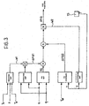
- Control of the temperature during the regeneration process of the filter PT can conveniently take place according to the diagram of Figure 3 .
- the unit PCU is arranged to make an open loop determination of the partial quantity of fuel PIQ to be introduced into the cylinders C1-C4 of the engine ICE in a post-injection phase, in dependence on the speed of rotation n of the engine and the overall quantity q of fuel to be injected into the cylinders at each injection.
- the determination of the partial quantity PIQ of fuel to be injected in the post injection phase is determined for example by means of a map (map PIQ) stored in the memory devices M.
- the unit PCU is moreover arranged to modify the said partial quantity of fuel PIQ to be injected into the engine in the post injection phase, by adding/subtracting a first correction quantity ⁇ PIQ1 determined according to a mapped function of the speed of rotation n of the engine and the quantity q of fuel injected into the cylinders "weighted" as a function of the values assumed by some ambient quantities (such as the air temperature T A and the atmospheric pressure P) and engine quantities (such as temperature T c of the engine coolant), via a factor W1 obtained by means of a suitable pre-memorised weighting map.
- a first correction quantity ⁇ PIQ1 determined according to a mapped function of the speed of rotation n of the engine and the quantity q of fuel injected into the cylinders "weighted" as a function of the values assumed by some ambient quantities (such as the air temperature T A and the atmospheric pressure P) and engine quantities (such as temperature T c of the engine coolant), via a factor W1 obtained by means of a suitable pre
- the quantity PIQ is further modified by adding/subtracting from it a second correction quantity ⁇ PIQ2, generated in an open loop determination as a function of the difference between the effective temperature T of the exhaust gas at the inlet of the filter PT (detected by means of the sensor TS) and a predetermined reference temperature T sp .
- the correction quantity ⁇ PIQ2 can conveniently be determined by means of a PID governor (Proportional-Integral-Derivative).
- the effective partial quantity of fuel ⁇ PIQ to be injected into the engine in the post-injection phase during the regeneration process of the filter is obtained.
- the process and control unit PCU is arranged to end a regeneration phase of the filter PT after a predetermined working time t* has passed since the beginning of this regeneration, which is conveniently variable in a predetermined manner as a function of the type of journey or trip MPi made by the motor vehicle during the regeneration.
- the working time t* is defined as the percentage of time for which the temperature in the filter PT is effectively above the predetermined value (for example 650°).
- the unit PCU is further arranged to calculate the residual quantity Q 0 of unburnt particulates in the filter, at the end of a filter regeneration phase, according to a further predetermined estimation function, and to assume this residual quantity as the initial value for the calculation of the quantity of particulates accumulated in the filter starting from the end of this regeneration phase.
- the residual particulates at the completion of regeneration is conveniently calculated in a variable manner as a function of the type of journey or trip made during regeneration.
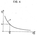
- the residual particulates can be calculated on the basis of an estimation function such as that (essentially a decreasing exponential) which is qualitatively shown in Figure 4 .
- This function can also be utilised in particular to estimate the residual quantity of unburnt particulates in the filter PT when, during a filter regeneration phase, the motor ICE is switched off before completion of this regeneration phase.
Landscapes
- Engineering & Computer Science (AREA)
- Chemical & Material Sciences (AREA)
- Combustion & Propulsion (AREA)
- Mechanical Engineering (AREA)
- General Engineering & Computer Science (AREA)
- Chemical Kinetics & Catalysis (AREA)
- Processes For Solid Components From Exhaust (AREA)
Description
- The present invention relates to a process for the removal of particulates from the exhaust gas of an internal combustion engine, in particular a diesel engine of a motor vehicle, provided with a plurality of fuel injectors, of the kind defined in the preamble of claim 1.
-
EP 0 859 132 A1 discloses a process or method of this kind in which different engine "operating zones" are preliminarily defined for the engine of a car provided with a navigation system and a receiver capable of receiving traffic congestion forecast information. - Before the car is started to reach a desired destination, the route searched by the navigation system is divided into a number of route sections. For each route section an amount of generated particulate is predicted, and the corresponding engine operating zone is determined still while the car is not running.
- After the car begins running, on the basis of the actual values of some vehicle parameters an electronic control unit checks whether the actual behaviour of the car actually corresponds to the previously predicted particulate generation schedule. In the negative case, the particulate generation outline is rescheduled.
-
EP 1 195 508 discloses a particulate filter regeneration method wherein a vehicle mission profile is determined as a function of the detected combustion chamber pressure and the engine speed, and as a function of the temperature of the exhaust gases and the vehicle speed. -
EP 1 108 866 A2 discloses a system for the determination of the particulates accumulated in a filter in a motor vehicle provided with a diesel engine. A control unit receives signals indicating the injected fuel quantity and the engine speed, and from a characteristics diagram determines the corresponding quantity of particulate accumulated in the filter in a time interval. - One object of the present invention is to provide an improved process of the initially defined kind.
- This object is achieved according to the invention with a process the characteristics of which are defined in the annexed Claim 1.
- Further characteristics and advantages of the invention will become apparent from the following detailed description, given purely by way of non-limitative example, with reference to the attached drawings, in which:
-
Figure 1 is a systematic representation of a system operating according to the invention; -
Figure 2 is a graph which qualitatively demonstrates, as a function of the speed of rotation of the engine n plotted on the abscissa, the quantity g of fuel injected into the engine, for the various types of journey or trip of a motor vehicle; -
Figure 3 is a block diagram which illustrates one control mode for controlling the quantity of fuel injected into the cylinders of the engine in a post-injection phase, in a process according to the invention; and -
Figure 4 is a further diagram which shows, as a function of the type t* of regeneration used, plotted on abscissa, the variation of a function which represents concentration of particulates in the filter during a regeneration phase. - With reference to the drawings, in
Figure 1 the reference number ICE generally indicates an internal combustion engine, for example a diesel cycle engine. In the illustrated example this engine has four cylinders C1-C4 disposed in line, but the invention is not limited to this configuration. - Each of the cylinders of the engine ICE is associated with a respective injector I1-I4, controlled by an electronic unit ECU.
- The engine ICE is associated with an exhaust manifold EP, in which, in the illustrated example, and in a manner known per se, are fitted first and second catalytic converters CC1 and CC2. Associated with the second, which is disposed downstream of the first, is a particulate filtration device indicated PT. An electric temperature sensor TS is associated with the input of the filter PT to provide, in operation, electrical signals indicative of the temperature of the exhaust gas at the inlet of this filter.
- The sensor TS is connected to an electronic processor and control unit PCU. In the exemplary embodiment illustrated in
Figure 1 this unit PCU is shown as a separate and distinct element from the unit ECU which controls the engine injectors. It will be apparent to those skilled in the art, however, that in place of two physically separate interconnected units, it is possible to make use of a single electronic unit arranged to perform the functions of both the units ECU and PCU. - To the unit PCU are further connected devices S1-S5 which provide it with electrical signals indicative of the speed of rotation n (number of revolutions per unit of time) of the engine ICE, the quantity q of fuel injected into the cylinders of the engine ICE, the temperature Tc of the coolant liquid of the engine ICE, the atmospheric pressure P and the temperature TA of the aspirated air.
- Memory devices M are also associated with the unit PCU. Although in
Figure 1 these memory devices are illustrated as separate from the unit PCU it will be apparent to the man skilled in the art that such memory devices could be integrated in the PCU memory or even in the unit ECU. - The processing and control unit PCU is arranged to perform, in cooperation with unit ECU, filter regeneration phases of the filter PT by controlling the fuel injectors I1-I4 in a predetermined manner as a function of the signals provided by the devices S1-S5 and TS in such a way to cause a controlled increase in the temperature of the exhaust gas so as to cause combustion of the particulates accumulated in the said filter.
- In the above-described system the processing and control unit PCU is, for this purpose, arranged to identify in operation the type of journey or trip in which the motor vehicle is engaged at any instant from among a plurality of predetermined types of journey or trip. The identification of the type of journey or trip is performed of the basis of the signals provided from the devices S1 and S2, that is to say as a function of the instantaneous speed of rotation n of the engine ICE and of the quantity of fuel q injected into the said engine.
- The type of journey or trip which the motor vehicle is making is determined on the basis of the results of a statistical analysis, and on the basis of a diagram of the type qualitatively illustrated in
Figure 2 . In this figure the quantity q of fuel injected is plotted on the ordinate as a function of the speed of rotation n of the engine. In this figure the curve indicated A is the curve corresponding to operating condition of the engine with the accelerator pressed 100%, that is to say the curve corresponding to the maximum delivery of power by the engine ICE. - The region underlying the curve A is divided, (on the basis of experimental detections) into a plurality of ranges of values each corresponding to the profile of a particular type of journey or trip of the motor vehicle. In the illustrated example there are indicated substantially four ranges indicated MP1-MP4 corresponding, in order, a type of journey or trip in the city ("urban driving"), a mountain journey, motorway driving and, finally the so-called mixed journeys.
- A diagram of the type illustrated by way of example in
Figure 2 is memorised in the system, for example in the memory devices M associated with the unit PCU, for example in the form of the table or map. In operation the unit PCU is arranged to acquire the signals indicative of the speed of rotation n and of the injected quantity q of fuel, and to average the corresponding values, acquired for example each 20 ms within the ambit of a movable time window, for example of 5 minutes. On the basis of the averaged values thus obtained the unit PCU determines the type of trip or current journey profile MPi (with i=1, ..., 4 in the example ofFigure 2 ). - The processing and control unit PCU is, moreover, set up to calculate, as a function of a predefined estimate, and in dependence on the type of journey or trip Mpi, the quantity q of particulate material gradually accumulated in the filter PT, and to start the regeneration phase of this filter when the quantity of particulates accumulated in the filter, as calculated, exceeds the predetermined threshold.
- The unit PCU in particular is arranged to calculate the quantity of particulates Q accumulated in the filter PT on the basis of a predetermined function I indicative of the rate of accumulation (for example in g/h) of particulates in the filter PT, predetermined and memorised for the said type of journey or trip MPi of the motor vehicle. It has been found in this way that the accumulation of particulates in the filter is an essentially linear process over time, depending on the various conditions of use of the engine of the motor vehicle, that is to say to the profile of the various types of journey or trip which the motor vehicle is making. The function I=I (t, MPi) is conveniently determined in a statistical manner and is memorised in the system as a function of the various types of journey the vehicle may make.
- In operation, the quantity Q of particulates accumulated at each instant is then calculated by the unit PCU as an integral over time of the various accumulation rates upon variation of the journey or trip profile of the vehicle, essentially according to a relation of the type:

- When the quantity Q of accumulated particulates exceeds the predetermined threshold the unit PCU causes commencement of a new regeneration phase.
- Conveniently the comparison threshold is predetermined with prefixed values according to the type of journey or trip which the motor vehicle is making at the time.
- In the regeneration phase a spontaneous combustion of the particulates takes place as soon as and as long as the exhaust gas of the engine, at the inlet of the filter itself, reaches temperatures greater than a predetermined value, for example 650°C, in the presence of a sufficient percentage of oxygen.
- The processing and control unit PCU is arranged to control the temperature in the filter itself during a filter regeneration phase of the filter PT, causing a controlled increase of the exhaust gas temperature resulting in combustion of the particulates accumulated in the filter.
- Control of the temperature during the regeneration process of the filter PT can conveniently take place according to the diagram of
Figure 3 . In conformity with this diagram the unit PCU is arranged to make an open loop determination of the partial quantity of fuel PIQ to be introduced into the cylinders C1-C4 of the engine ICE in a post-injection phase, in dependence on the speed of rotation n of the engine and the overall quantity q of fuel to be injected into the cylinders at each injection. The determination of the partial quantity PIQ of fuel to be injected in the post injection phase is determined for example by means of a map (map PIQ) stored in the memory devices M. - The unit PCU is moreover arranged to modify the said partial quantity of fuel PIQ to be injected into the engine in the post injection phase, by adding/subtracting a first correction quantity ΔPIQ1 determined according to a mapped function of the speed of rotation n of the engine and the quantity q of fuel injected into the cylinders "weighted" as a function of the values assumed by some ambient quantities (such as the air temperature TA and the atmospheric pressure P) and engine quantities (such as temperature Tc of the engine coolant), via a factor W1 obtained by means of a suitable pre-memorised weighting map. The quantity PIQ is further modified by adding/subtracting from it a second correction quantity ΔPIQ2, generated in an open loop determination as a function of the difference between the effective temperature T of the exhaust gas at the inlet of the filter PT (detected by means of the sensor TS) and a predetermined reference temperature Tsp. The correction quantity ΔPIQ2 can conveniently be determined by means of a PID governor (Proportional-Integral-Derivative).
- Subsequently, following a further conditioning through a factor W2 obtained from a suitable map as a function of the value of the temperature T of the exhaust gas, the effective partial quantity of fuel ΔPIQ to be injected into the engine in the post-injection phase during the regeneration process of the filter is obtained.
- The process and control unit PCU is arranged to end a regeneration phase of the filter PT after a predetermined working time t* has passed since the beginning of this regeneration, which is conveniently variable in a predetermined manner as a function of the type of journey or trip MPi made by the motor vehicle during the regeneration. The working time t* is defined as the percentage of time for which the temperature in the filter PT is effectively above the predetermined value (for example 650°).
- The unit PCU is further arranged to calculate the residual quantity Q0 of unburnt particulates in the filter, at the end of a filter regeneration phase, according to a further predetermined estimation function, and to assume this residual quantity as the initial value for the calculation of the quantity of particulates accumulated in the filter starting from the end of this regeneration phase.
- The residual particulates at the completion of regeneration is conveniently calculated in a variable manner as a function of the type of journey or trip made during regeneration.
- If a regeneration phase is interrupted the residual particulates can be calculated on the basis of an estimation function such as that (essentially a decreasing exponential) which is qualitatively shown in
Figure 4 . - In this Figure, along the ordinate is plotted the rate of percentage decrease I* of the particulates in the filter during regeneration upon variation of the regeneration working time t* which is plotted along the abscissa.
- This function can also be utilised in particular to estimate the residual quantity of unburnt particulates in the filter PT when, during a filter regeneration phase, the motor ICE is switched off before completion of this regeneration phase.
- Naturally, the principle of the invention remaining the same, the embodiments and details of construction can be widely varied with respect to what has be described and illustrated purely by way of non-limitative example, without by this departing from the ambit of the invention as defined in the annexed claims.
Claims (6)
- A process for the removal of particulates from the exhaust gas of an internal combustion engine, in particular a diesel engine (ICE) of a motor vehicle provided with a plurality of fuel injectors (I1-I4), the process comprising the operations of:arranging a filter (PT) in the exhaust duct (EP) of the engine (ICE) operable to retain the particulates contained in the exhaust gas;generating, by indicator means (S1-S5), electrical signals indicative of the values of operating parameters (NQ) of the engine (ICE);performing, by processor and control means (PCU, ECU) filter regeneration phases of the filter (PT) in a predetermined manner as a function of the signals provided by the said indicator means (S1-S5) in such a way as to cause an increase in the temperature of the exhaust gas so as to cause a combustion of the particulates accumulated in the filter (PT);the process comprising further the operations of:identifying, by means of the said processor and control means (PCU, ECU), the type of journey or trip (MPi) of the motor vehicle from among a plurality of predefined types of journey or trip (MP1-MP4);calculating by means of the said processor and control means (PCU, ECU) and according to a predefined estimation function in dependence on the instantaneous type of journey or trip (MPi) the quantity of particulates (Q) gradually accumulated in the filter (PT); andstarting a filter regeneration phase of the filter (PT) when the calculated quantity (Q) of particulates accumulated in the filter (PT) exceeds a predetermined threshold; the process being characterized in thatsaid regeneration phases of the filter (PT) are performed by controlling the injectors (I1-I4) of the engine (ICE), and in thatthe said indicator means (S1-S5) are operable to provide to the processor and control means (PCU, ECU) electrical signals indicative of the instantaneous values of the speed of rotation (n) of the engine (ICE) and the quantity (q) of fuel injected into the engine (ICE); andthe processor and control means (PCU, ECU) are arranged to recognise the current type of journey or trip (MPi) of the motor vehicle on the basis of instantaneous values of the speed of rotation (n) of the engine (ICE) and of the quantity (q) of fuel injected and calculate the quantity (Q) of particulates accumulated in the filter (PT) on the basis of a predetermined function (I) indicative of the rate of accumulation of the particulates (PT) memorised for the said types of journey or trip (MPi) of the motor vehicle.
- A process according to Claim 1, in which the said threshold is determined by predetermined values according to the instantaneous type of journey or trip (MPi) of the motor vehicle.
- A process according to Claim 1 or Claim 2, in which the said function (I) indicative of the rate of accumulation is a linear function in time which is different for each type of journey or trip (MPi) of the motor vehicle.
- A process according to any of Claims 1 to 3, in which the said processor and control means (PCU, ECU) are arranged to terminate a filter regeneration phase of the filter (PT) after a predetermined working time (t*) has elapsed since commencement, which time is variable in a predetermined manner as a function of the types of journey or trip (MPi) made by the motor vehicle during regeneration.
- A process according to Claims 1 and 4, in which the said processor and control means (PCE, ECU) are arranged to calculate, at the end of a filter regeneration phase of the filter (PT) the residual quantity of unburnt particulates in the filter (PT) as a function of the type of journey or trip made during regeneration, and to assume this residual quantity as the initial value (Q0) for the calculation of the quantity (Q) of particulates accumulated in the filter starting from the end of this regeneration phase.
- A process according to Claim 5, in which the said processor and control means (PCU, ECU) are arranged to be able to calculate, by means of a predetermined estimation function, the residual quantity of unburnt particulates (Q0) in the filter (PT) in the case of interruption of a filter regeneration phase (PT) or when the engine (ICE) is switched off during a filter regeneration phase (PT).
Applications Claiming Priority (3)
| Application Number | Priority Date | Filing Date | Title |
|---|---|---|---|
| ITTO20030179 | 2003-03-11 | ||
| IT000179A ITTO20030179A1 (en) | 2003-03-11 | 2003-03-11 | PROCEDURE FOR REMOVING THE PARTICULATE FROM GAS |
| PCT/EP2004/002329 WO2004081359A1 (en) | 2003-03-11 | 2004-03-08 | Process for the removal of particulates from the exhaust gas of an internal combustion engine |
Publications (2)
| Publication Number | Publication Date |
|---|---|
| EP1608860A1 EP1608860A1 (en) | 2005-12-28 |
| EP1608860B1 true EP1608860B1 (en) | 2016-03-23 |
Family
ID=32983241
Family Applications (1)
| Application Number | Title | Priority Date | Filing Date |
|---|---|---|---|
| EP04718287.8A Expired - Lifetime EP1608860B1 (en) | 2003-03-11 | 2004-03-08 | Process for the removal of particulates from the exhaust gas of an internal combustion engine |
Country Status (6)
| Country | Link |
|---|---|
| US (1) | US20060236686A1 (en) |
| EP (1) | EP1608860B1 (en) |
| KR (1) | KR20060002814A (en) |
| CN (1) | CN1784541A (en) |
| IT (1) | ITTO20030179A1 (en) |
| WO (1) | WO2004081359A1 (en) |
Families Citing this family (12)
| Publication number | Priority date | Publication date | Assignee | Title |
|---|---|---|---|---|
| US7373809B2 (en) * | 2006-09-22 | 2008-05-20 | General Motors Corporation | Method for controlling a filter maintenance indicator |
| FR2916229A1 (en) * | 2007-05-16 | 2008-11-21 | Renault Sas | Pollutant e.g. soot, emission controlling method for motor vehicle, involves estimating quantity of injected fuel based on injection set point, and estimating soot mass from estimation of injected fuel quantity |
| US7908846B2 (en) * | 2007-12-19 | 2011-03-22 | Mack Trucks, Inc | Method for controlling injection in a diesel engine exhaust aftertreatment system and diesel engine with exhaust aftertreatment system |
| US8136351B2 (en) * | 2009-03-31 | 2012-03-20 | Woodward, Inc. | System and method for filtering diesel engine exhaust particulates |
| US9574483B2 (en) * | 2010-01-14 | 2017-02-21 | GM Global Technology Operations LLC | System and method for controlling exhaust gas temperature during particulate matter filter regeneration |
| JP5825791B2 (en) * | 2011-01-19 | 2015-12-02 | 三菱重工業株式会社 | Supercharger and diesel engine equipped with the same |
| JP6650675B2 (en) * | 2014-02-26 | 2020-02-19 | エフピーティー インダストリアル エス ピー エー | System for preventing accumulation of unburned hydrocarbons in the lines of exhaust gas aftertreatment systems of internal combustion engines |
| GB2531368B (en) * | 2015-02-11 | 2017-02-01 | Ford Global Tech Llc | A method for emissions regulation |
| KR101714268B1 (en) * | 2015-12-07 | 2017-03-08 | 현대자동차주식회사 | A method for preventing to regenerate dpf frequently using a method for analyzing driving pattern of vehicle |
| DE102016213147A1 (en) | 2016-07-19 | 2018-01-25 | Robert Bosch Gmbh | Method for operating an internal combustion engine |
| CN106351720B (en) * | 2016-11-30 | 2019-02-19 | 安徽江淮汽车集团股份有限公司 | A kind of method and system of the carbon accumulation amount of determining diesel particulate traps |
| CN107605583B (en) * | 2017-09-21 | 2019-09-17 | 北京汽车研究总院有限公司 | Diesel vehicle grain catcher tires out carbon amounts evaluation method |
Family Cites Families (6)
| Publication number | Priority date | Publication date | Assignee | Title |
|---|---|---|---|---|
| GB2239407B (en) * | 1989-12-27 | 1994-10-12 | Nissan Motor | Exhaust gas purifying device for an internal combustion engine |
| JP3106502B2 (en) | 1995-10-30 | 2000-11-06 | トヨタ自動車株式会社 | Exhaust gas purification device for internal combustion engine |
| DE19961159A1 (en) * | 1999-12-17 | 2001-08-16 | Volkswagen Ag | Method for determining a loading state of a particle filter of an internal combustion engine |
| DE10049659A1 (en) | 2000-10-07 | 2002-04-11 | Daimler Chrysler Ag | Adaptive regeneration management for exhaust gas treatment systems |
| FR2816357B1 (en) * | 2000-11-03 | 2003-02-07 | Peugeot Citroen Automobiles Sa | ASSISTANCE SYSTEM FOR THE REGENERATION OF A PARTICLE FILTER INTEGRATED IN AN EXHAUST SYSTEM OF A VEHICLE DIESEL ENGINE |
| JP4161546B2 (en) * | 2001-06-26 | 2008-10-08 | いすゞ自動車株式会社 | Regeneration control method for continuous regeneration type diesel particulate filter device |
-
2003
- 2003-03-11 IT IT000179A patent/ITTO20030179A1/en unknown
-
2004
- 2004-03-08 EP EP04718287.8A patent/EP1608860B1/en not_active Expired - Lifetime
- 2004-03-08 US US10/548,597 patent/US20060236686A1/en not_active Abandoned
- 2004-03-08 WO PCT/EP2004/002329 patent/WO2004081359A1/en not_active Ceased
- 2004-03-08 KR KR1020057017018A patent/KR20060002814A/en not_active Ceased
- 2004-03-08 CN CNA2004800123311A patent/CN1784541A/en active Pending
Also Published As
| Publication number | Publication date |
|---|---|
| ITTO20030179A1 (en) | 2004-09-12 |
| WO2004081359A1 (en) | 2004-09-23 |
| EP1608860A1 (en) | 2005-12-28 |
| US20060236686A1 (en) | 2006-10-26 |
| KR20060002814A (en) | 2006-01-09 |
| CN1784541A (en) | 2006-06-07 |
Similar Documents
| Publication | Publication Date | Title |
|---|---|---|
| RU2716098C2 (en) | System and method (embodiments) for adaptive regeneration of particulate filters in diesel engines | |
| US7200991B2 (en) | Regeneration control of diesel particulate filter | |
| US11286837B2 (en) | Control device for internal combustion engine | |
| EP0859132B1 (en) | Exhaust emission control apparatus for internal combustion engine | |
| KR100485316B1 (en) | Exhaust emission control system of internal combustion engine | |
| EP1890026B1 (en) | Control device for an internal combustion engine of a vehicle | |
| US11105247B2 (en) | Control device for internal combustion engine | |
| GB2402088A (en) | Diesel aftertreatment systems | |
| JP2004293340A (en) | Exhaust gas purifier | |
| US11203993B2 (en) | Method for operating an internal combustion engine | |
| US20060236686A1 (en) | Process for the removal of particulates from the exhaust gas of an internal combustion engine | |
| JPH09195751A (en) | Deterioration detection device for catalyst equipped with electric heater | |
| CN113074036A (en) | System and method for determining whether a DPF device is near full load for timely initiation of regeneration | |
| EP2754867B1 (en) | Warm-up system for exhaust system of internal combustion engine | |
| JP2785707B2 (en) | Exhaust gas purification device for internal combustion engine | |
| US20070256408A1 (en) | Particulate Matter Remaining Amount Estimating Method for Particulate Filter and Particulate Filter Regenerating Method | |
| GB2486416A (en) | Method for controlling the regeneration process of a lean NOx trap | |
| JP2962127B2 (en) | Control device for internal combustion engine | |
| WO2004081360A1 (en) | A process for control of the temperature in a device for filtering the exhaust gas of an internal combustion engine | |
| JP2001254616A (en) | Exhaust gas purification device for internal combustion engine | |
| US9115618B2 (en) | Method for the regeneration of a carbon particulate filter | |
| JP3788719B2 (en) | Exhaust gas purification device for internal combustion engine | |
| EP2775124A1 (en) | Internal combustion engine control device | |
| JP4151630B2 (en) | Exhaust gas purification method for internal combustion engine | |
| JP2001317388A (en) | Exhaust gas purification device for internal combustion engine |
Legal Events
| Date | Code | Title | Description |
|---|---|---|---|
| PUAI | Public reference made under article 153(3) epc to a published international application that has entered the european phase |
Free format text: ORIGINAL CODE: 0009012 |
|
| 17P | Request for examination filed |
Effective date: 20051011 |
|
| AK | Designated contracting states |
Kind code of ref document: A1 Designated state(s): AT BE BG CH CY CZ DE DK EE ES FI FR GB GR HU IE IT LI LU MC NL PL PT RO SE SI SK TR |
|
| AX | Request for extension of the european patent |
Extension state: AL LT LV MK |
|
| DAX | Request for extension of the european patent (deleted) | ||
| RIN1 | Information on inventor provided before grant (corrected) |
Inventor name: BARUCCHI, ENRICO Inventor name: RELLECATI, PIERLUIGI Inventor name: IMARISIO, ROBERTO |
|
| 17Q | First examination report despatched |
Effective date: 20090416 |
|
| GRAJ | Information related to disapproval of communication of intention to grant by the applicant or resumption of examination proceedings by the epo deleted |
Free format text: ORIGINAL CODE: EPIDOSDIGR1 |
|
| GRAP | Despatch of communication of intention to grant a patent |
Free format text: ORIGINAL CODE: EPIDOSNIGR1 |
|
| GRAJ | Information related to disapproval of communication of intention to grant by the applicant or resumption of examination proceedings by the epo deleted |
Free format text: ORIGINAL CODE: EPIDOSDIGR1 |
|
| GRAP | Despatch of communication of intention to grant a patent |
Free format text: ORIGINAL CODE: EPIDOSNIGR1 |
|
| INTG | Intention to grant announced |
Effective date: 20150901 |
|
| INTG | Intention to grant announced |
Effective date: 20150914 |
|
| GRAS | Grant fee paid |
Free format text: ORIGINAL CODE: EPIDOSNIGR3 |
|
| GRAA | (expected) grant |
Free format text: ORIGINAL CODE: 0009210 |
|
| RIN1 | Information on inventor provided before grant (corrected) |
Inventor name: RELLECATI, PIERLUIGI Inventor name: IMARISIO, ROBERTO Inventor name: BARUCCHI, ENRICO |
|
| RIN1 | Information on inventor provided before grant (corrected) |
Inventor name: RELLECATI, PIERLUIGI Inventor name: IMARISIO, ROBERTO Inventor name: BARUCCHI, ENRICO |
|
| AK | Designated contracting states |
Kind code of ref document: B1 Designated state(s): AT BE BG CH CY CZ DE DK EE ES FI FR GB GR HU IE IT LI LU MC NL PL PT RO SE SI SK TR |
|
| REG | Reference to a national code |
Ref country code: GB Ref legal event code: FG4D |
|
| REG | Reference to a national code |
Ref country code: CH Ref legal event code: EP |
|
| REG | Reference to a national code |
Ref country code: AT Ref legal event code: REF Ref document number: 783409 Country of ref document: AT Kind code of ref document: T Effective date: 20160415 |
|
| REG | Reference to a national code |
Ref country code: IE Ref legal event code: FG4D |
|
| REG | Reference to a national code |
Ref country code: DE Ref legal event code: R096 Ref document number: 602004048872 Country of ref document: DE |
|
| REG | Reference to a national code |
Ref country code: NL Ref legal event code: MP Effective date: 20160323 |
|
| PG25 | Lapsed in a contracting state [announced via postgrant information from national office to epo] |
Ref country code: GR Free format text: LAPSE BECAUSE OF FAILURE TO SUBMIT A TRANSLATION OF THE DESCRIPTION OR TO PAY THE FEE WITHIN THE PRESCRIBED TIME-LIMIT Effective date: 20160624 Ref country code: FI Free format text: LAPSE BECAUSE OF FAILURE TO SUBMIT A TRANSLATION OF THE DESCRIPTION OR TO PAY THE FEE WITHIN THE PRESCRIBED TIME-LIMIT Effective date: 20160323 |
|
| REG | Reference to a national code |
Ref country code: AT Ref legal event code: MK05 Ref document number: 783409 Country of ref document: AT Kind code of ref document: T Effective date: 20160323 |
|
| PG25 | Lapsed in a contracting state [announced via postgrant information from national office to epo] |
Ref country code: NL Free format text: LAPSE BECAUSE OF FAILURE TO SUBMIT A TRANSLATION OF THE DESCRIPTION OR TO PAY THE FEE WITHIN THE PRESCRIBED TIME-LIMIT Effective date: 20160323 Ref country code: SE Free format text: LAPSE BECAUSE OF FAILURE TO SUBMIT A TRANSLATION OF THE DESCRIPTION OR TO PAY THE FEE WITHIN THE PRESCRIBED TIME-LIMIT Effective date: 20160323 |
|
| PG25 | Lapsed in a contracting state [announced via postgrant information from national office to epo] |
Ref country code: EE Free format text: LAPSE BECAUSE OF FAILURE TO SUBMIT A TRANSLATION OF THE DESCRIPTION OR TO PAY THE FEE WITHIN THE PRESCRIBED TIME-LIMIT Effective date: 20160323 Ref country code: PL Free format text: LAPSE BECAUSE OF FAILURE TO SUBMIT A TRANSLATION OF THE DESCRIPTION OR TO PAY THE FEE WITHIN THE PRESCRIBED TIME-LIMIT Effective date: 20160323 |
|
| PG25 | Lapsed in a contracting state [announced via postgrant information from national office to epo] |
Ref country code: ES Free format text: LAPSE BECAUSE OF FAILURE TO SUBMIT A TRANSLATION OF THE DESCRIPTION OR TO PAY THE FEE WITHIN THE PRESCRIBED TIME-LIMIT Effective date: 20160323 Ref country code: PT Free format text: LAPSE BECAUSE OF FAILURE TO SUBMIT A TRANSLATION OF THE DESCRIPTION OR TO PAY THE FEE WITHIN THE PRESCRIBED TIME-LIMIT Effective date: 20160725 Ref country code: SK Free format text: LAPSE BECAUSE OF FAILURE TO SUBMIT A TRANSLATION OF THE DESCRIPTION OR TO PAY THE FEE WITHIN THE PRESCRIBED TIME-LIMIT Effective date: 20160323 Ref country code: RO Free format text: LAPSE BECAUSE OF FAILURE TO SUBMIT A TRANSLATION OF THE DESCRIPTION OR TO PAY THE FEE WITHIN THE PRESCRIBED TIME-LIMIT Effective date: 20160323 Ref country code: AT Free format text: LAPSE BECAUSE OF FAILURE TO SUBMIT A TRANSLATION OF THE DESCRIPTION OR TO PAY THE FEE WITHIN THE PRESCRIBED TIME-LIMIT Effective date: 20160323 Ref country code: CZ Free format text: LAPSE BECAUSE OF FAILURE TO SUBMIT A TRANSLATION OF THE DESCRIPTION OR TO PAY THE FEE WITHIN THE PRESCRIBED TIME-LIMIT Effective date: 20160323 |
|
| PG25 | Lapsed in a contracting state [announced via postgrant information from national office to epo] |
Ref country code: BE Free format text: LAPSE BECAUSE OF FAILURE TO SUBMIT A TRANSLATION OF THE DESCRIPTION OR TO PAY THE FEE WITHIN THE PRESCRIBED TIME-LIMIT Effective date: 20160323 |
|
| REG | Reference to a national code |
Ref country code: DE Ref legal event code: R097 Ref document number: 602004048872 Country of ref document: DE |
|
| PLBE | No opposition filed within time limit |
Free format text: ORIGINAL CODE: 0009261 |
|
| STAA | Information on the status of an ep patent application or granted ep patent |
Free format text: STATUS: NO OPPOSITION FILED WITHIN TIME LIMIT |
|
| PG25 | Lapsed in a contracting state [announced via postgrant information from national office to epo] |
Ref country code: DK Free format text: LAPSE BECAUSE OF FAILURE TO SUBMIT A TRANSLATION OF THE DESCRIPTION OR TO PAY THE FEE WITHIN THE PRESCRIBED TIME-LIMIT Effective date: 20160323 |
|
| PG25 | Lapsed in a contracting state [announced via postgrant information from national office to epo] |
Ref country code: BG Free format text: LAPSE BECAUSE OF FAILURE TO SUBMIT A TRANSLATION OF THE DESCRIPTION OR TO PAY THE FEE WITHIN THE PRESCRIBED TIME-LIMIT Effective date: 20160623 |
|
| 26N | No opposition filed |
Effective date: 20170102 |
|
| REG | Reference to a national code |
Ref country code: FR Ref legal event code: PLFP Year of fee payment: 14 |
|
| PG25 | Lapsed in a contracting state [announced via postgrant information from national office to epo] |
Ref country code: SI Free format text: LAPSE BECAUSE OF FAILURE TO SUBMIT A TRANSLATION OF THE DESCRIPTION OR TO PAY THE FEE WITHIN THE PRESCRIBED TIME-LIMIT Effective date: 20160323 |
|
| REG | Reference to a national code |
Ref country code: CH Ref legal event code: PL |
|
| GBPC | Gb: european patent ceased through non-payment of renewal fee |
Effective date: 20170308 |
|
| PG25 | Lapsed in a contracting state [announced via postgrant information from national office to epo] |
Ref country code: MC Free format text: LAPSE BECAUSE OF FAILURE TO SUBMIT A TRANSLATION OF THE DESCRIPTION OR TO PAY THE FEE WITHIN THE PRESCRIBED TIME-LIMIT Effective date: 20160323 |
|
| REG | Reference to a national code |
Ref country code: IE Ref legal event code: MM4A |
|
| PG25 | Lapsed in a contracting state [announced via postgrant information from national office to epo] |
Ref country code: LU Free format text: LAPSE BECAUSE OF NON-PAYMENT OF DUE FEES Effective date: 20170308 |
|
| PG25 | Lapsed in a contracting state [announced via postgrant information from national office to epo] |
Ref country code: GB Free format text: LAPSE BECAUSE OF NON-PAYMENT OF DUE FEES Effective date: 20170308 Ref country code: CH Free format text: LAPSE BECAUSE OF NON-PAYMENT OF DUE FEES Effective date: 20170331 Ref country code: IE Free format text: LAPSE BECAUSE OF NON-PAYMENT OF DUE FEES Effective date: 20170308 Ref country code: LI Free format text: LAPSE BECAUSE OF NON-PAYMENT OF DUE FEES Effective date: 20170331 |
|
| REG | Reference to a national code |
Ref country code: FR Ref legal event code: PLFP Year of fee payment: 15 |
|
| PG25 | Lapsed in a contracting state [announced via postgrant information from national office to epo] |
Ref country code: HU Free format text: LAPSE BECAUSE OF FAILURE TO SUBMIT A TRANSLATION OF THE DESCRIPTION OR TO PAY THE FEE WITHIN THE PRESCRIBED TIME-LIMIT; INVALID AB INITIO Effective date: 20040308 |
|
| PG25 | Lapsed in a contracting state [announced via postgrant information from national office to epo] |
Ref country code: CY Free format text: LAPSE BECAUSE OF NON-PAYMENT OF DUE FEES Effective date: 20160323 |
|
| PG25 | Lapsed in a contracting state [announced via postgrant information from national office to epo] |
Ref country code: TR Free format text: LAPSE BECAUSE OF FAILURE TO SUBMIT A TRANSLATION OF THE DESCRIPTION OR TO PAY THE FEE WITHIN THE PRESCRIBED TIME-LIMIT Effective date: 20160323 |
|
| PGFP | Annual fee paid to national office [announced via postgrant information from national office to epo] |
Ref country code: IT Payment date: 20210308 Year of fee payment: 18 Ref country code: FR Payment date: 20210330 Year of fee payment: 18 |
|
| PGFP | Annual fee paid to national office [announced via postgrant information from national office to epo] |
Ref country code: DE Payment date: 20210319 Year of fee payment: 18 |
|
| REG | Reference to a national code |
Ref country code: DE Ref legal event code: R119 Ref document number: 602004048872 Country of ref document: DE |
|
| PG25 | Lapsed in a contracting state [announced via postgrant information from national office to epo] |
Ref country code: FR Free format text: LAPSE BECAUSE OF NON-PAYMENT OF DUE FEES Effective date: 20220331 Ref country code: DE Free format text: LAPSE BECAUSE OF NON-PAYMENT OF DUE FEES Effective date: 20221001 |
|
| PG25 | Lapsed in a contracting state [announced via postgrant information from national office to epo] |
Ref country code: IT Free format text: LAPSE BECAUSE OF NON-PAYMENT OF DUE FEES Effective date: 20220308 |