EP1608250B1 - A combination, comprising a compartment, a closure, and at least one fasterner, the combination forming an array with other combinations - Google Patents
A combination, comprising a compartment, a closure, and at least one fasterner, the combination forming an array with other combinations Download PDFInfo
- Publication number
- EP1608250B1 EP1608250B1 EP04721087.7A EP04721087A EP1608250B1 EP 1608250 B1 EP1608250 B1 EP 1608250B1 EP 04721087 A EP04721087 A EP 04721087A EP 1608250 B1 EP1608250 B1 EP 1608250B1
- Authority
- EP
- European Patent Office
- Prior art keywords
- combination
- closure
- fastener
- compartment
- opening
- Prior art date
- Legal status (The legal status is an assumption and is not a legal conclusion. Google has not performed a legal analysis and makes no representation as to the accuracy of the status listed.)
- Expired - Lifetime
Links
Images



Classifications
-
- E—FIXED CONSTRUCTIONS
- E05—LOCKS; KEYS; WINDOW OR DOOR FITTINGS; SAFES
- E05F—DEVICES FOR MOVING WINGS INTO OPEN OR CLOSED POSITION; CHECKS FOR WINGS; WING FITTINGS NOT OTHERWISE PROVIDED FOR, CONCERNED WITH THE FUNCTIONING OF THE WING
- E05F15/00—Power-operated mechanisms for wings
- E05F15/70—Power-operated mechanisms for wings with automatic actuation
- E05F15/77—Power-operated mechanisms for wings with automatic actuation using wireless control
-
- A—HUMAN NECESSITIES
- A47—FURNITURE; DOMESTIC ARTICLES OR APPLIANCES; COFFEE MILLS; SPICE MILLS; SUCTION CLEANERS IN GENERAL
- A47G—HOUSEHOLD OR TABLE EQUIPMENT
- A47G29/00—Supports, holders, or containers for household use, not provided for in groups A47G1/00-A47G27/00 or A47G33/00
- A47G29/12—Mail or newspaper receptacles, e.g. letter-boxes; Openings in doors or the like for delivering mail or newspapers
- A47G29/1201—Letter-box assemblies for apartment buildings
-
- A—HUMAN NECESSITIES
- A47—FURNITURE; DOMESTIC ARTICLES OR APPLIANCES; COFFEE MILLS; SPICE MILLS; SUCTION CLEANERS IN GENERAL
- A47G—HOUSEHOLD OR TABLE EQUIPMENT
- A47G29/00—Supports, holders, or containers for household use, not provided for in groups A47G1/00-A47G27/00 or A47G33/00
- A47G29/12—Mail or newspaper receptacles, e.g. letter-boxes; Openings in doors or the like for delivering mail or newspapers
- A47G29/122—Parts, details, or accessories, e.g. signalling devices, lamps, devices for leaving messages
- A47G29/1225—Signalling devices
-
- A—HUMAN NECESSITIES
- A47—FURNITURE; DOMESTIC ARTICLES OR APPLIANCES; COFFEE MILLS; SPICE MILLS; SUCTION CLEANERS IN GENERAL
- A47G—HOUSEHOLD OR TABLE EQUIPMENT
- A47G29/00—Supports, holders, or containers for household use, not provided for in groups A47G1/00-A47G27/00 or A47G33/00
- A47G29/12—Mail or newspaper receptacles, e.g. letter-boxes; Openings in doors or the like for delivering mail or newspapers
- A47G29/122—Parts, details, or accessories, e.g. signalling devices, lamps, devices for leaving messages
- A47G29/124—Appliances to prevent unauthorised removal of contents
-
- E—FIXED CONSTRUCTIONS
- E05—LOCKS; KEYS; WINDOW OR DOOR FITTINGS; SAFES
- E05B—LOCKS; ACCESSORIES THEREFOR; HANDCUFFS
- E05B41/00—Locks with visible indication as to whether the lock is locked or unlocked
-
- E—FIXED CONSTRUCTIONS
- E05—LOCKS; KEYS; WINDOW OR DOOR FITTINGS; SAFES
- E05B—LOCKS; ACCESSORIES THEREFOR; HANDCUFFS
- E05B47/00—Operating or controlling locks or other fastening devices by electric or magnetic means
- E05B47/0001—Operating or controlling locks or other fastening devices by electric or magnetic means with electric actuators; Constructional features thereof
- E05B47/0009—Operating or controlling locks or other fastening devices by electric or magnetic means with electric actuators; Constructional features thereof with thermo-electric actuators, e.g. heated bimetals
-
- G—PHYSICS
- G06—COMPUTING OR CALCULATING; COUNTING
- G06Q—INFORMATION AND COMMUNICATION TECHNOLOGY [ICT] SPECIALLY ADAPTED FOR ADMINISTRATIVE, COMMERCIAL, FINANCIAL, MANAGERIAL OR SUPERVISORY PURPOSES; SYSTEMS OR METHODS SPECIALLY ADAPTED FOR ADMINISTRATIVE, COMMERCIAL, FINANCIAL, MANAGERIAL OR SUPERVISORY PURPOSES, NOT OTHERWISE PROVIDED FOR
- G06Q20/00—Payment architectures, schemes or protocols
- G06Q20/08—Payment architectures
- G06Q20/10—Payment architectures specially adapted for electronic funds transfer [EFT] systems; specially adapted for home banking systems
-
- A—HUMAN NECESSITIES
- A47—FURNITURE; DOMESTIC ARTICLES OR APPLIANCES; COFFEE MILLS; SPICE MILLS; SUCTION CLEANERS IN GENERAL
- A47G—HOUSEHOLD OR TABLE EQUIPMENT
- A47G29/00—Supports, holders, or containers for household use, not provided for in groups A47G1/00-A47G27/00 or A47G33/00
- A47G29/12—Mail or newspaper receptacles, e.g. letter-boxes; Openings in doors or the like for delivering mail or newspapers
- A47G29/122—Parts, details, or accessories, e.g. signalling devices, lamps, devices for leaving messages
- A47G29/1225—Signalling devices
- A47G2029/1226—Signalling devices comprising electrical parts
-
- E—FIXED CONSTRUCTIONS
- E05—LOCKS; KEYS; WINDOW OR DOOR FITTINGS; SAFES
- E05B—LOCKS; ACCESSORIES THEREFOR; HANDCUFFS
- E05B65/00—Locks or fastenings for special use
- E05B65/02—Locks or fastenings for special use for thin, hollow, or thin-metal wings
- E05B65/025—Locks or fastenings for special use for thin, hollow, or thin-metal wings for lockers
-
- E—FIXED CONSTRUCTIONS
- E05—LOCKS; KEYS; WINDOW OR DOOR FITTINGS; SAFES
- E05Y—INDEXING SCHEME ASSOCIATED WITH SUBCLASSES E05D AND E05F, RELATING TO CONSTRUCTION ELEMENTS, ELECTRIC CONTROL, POWER SUPPLY, POWER SIGNAL OR TRANSMISSION, USER INTERFACES, MOUNTING OR COUPLING, DETAILS, ACCESSORIES, AUXILIARY OPERATIONS NOT OTHERWISE PROVIDED FOR, APPLICATION THEREOF
- E05Y2999/00—Subject-matter not otherwise provided for in this subclass
-
- G—PHYSICS
- G07—CHECKING-DEVICES
- G07C—TIME OR ATTENDANCE REGISTERS; REGISTERING OR INDICATING THE WORKING OF MACHINES; GENERATING RANDOM NUMBERS; VOTING OR LOTTERY APPARATUS; ARRANGEMENTS, SYSTEMS OR APPARATUS FOR CHECKING NOT PROVIDED FOR ELSEWHERE
- G07C2209/00—Indexing scheme relating to groups G07C9/00 - G07C9/38
- G07C2209/60—Indexing scheme relating to groups G07C9/00174 - G07C9/00944
- G07C2209/62—Comprising means for indicating the status of the lock
-
- G—PHYSICS
- G07—CHECKING-DEVICES
- G07C—TIME OR ATTENDANCE REGISTERS; REGISTERING OR INDICATING THE WORKING OF MACHINES; GENERATING RANDOM NUMBERS; VOTING OR LOTTERY APPARATUS; ARRANGEMENTS, SYSTEMS OR APPARATUS FOR CHECKING NOT PROVIDED FOR ELSEWHERE
- G07C9/00—Individual registration on entry or exit
- G07C9/00174—Electronically operated locks; Circuits therefor; Nonmechanical keys therefor, e.g. passive or active electrical keys or other data carriers without mechanical keys
- G07C9/00896—Electronically operated locks; Circuits therefor; Nonmechanical keys therefor, e.g. passive or active electrical keys or other data carriers without mechanical keys specially adapted for particular uses
- G07C9/00912—Electronically operated locks; Circuits therefor; Nonmechanical keys therefor, e.g. passive or active electrical keys or other data carriers without mechanical keys specially adapted for particular uses for safes, strong-rooms, vaults or the like
-
- Y—GENERAL TAGGING OF NEW TECHNOLOGICAL DEVELOPMENTS; GENERAL TAGGING OF CROSS-SECTIONAL TECHNOLOGIES SPANNING OVER SEVERAL SECTIONS OF THE IPC; TECHNICAL SUBJECTS COVERED BY FORMER USPC CROSS-REFERENCE ART COLLECTIONS [XRACs] AND DIGESTS
- Y10—TECHNICAL SUBJECTS COVERED BY FORMER USPC
- Y10T—TECHNICAL SUBJECTS COVERED BY FORMER US CLASSIFICATION
- Y10T24/00—Buckles, buttons, clasps, etc.
- Y10T24/45—Separable-fastener or required component thereof [e.g., projection and cavity to complete interlock]
- Y10T24/45225—Separable-fastener or required component thereof [e.g., projection and cavity to complete interlock] including member having distinct formations and mating member selectively interlocking therewith
- Y10T24/45471—Projection having movable connection between components thereof or variable configuration
- Y10T24/45482—Projection having movable connection between components thereof or variable configuration and operator therefor
-
- Y—GENERAL TAGGING OF NEW TECHNOLOGICAL DEVELOPMENTS; GENERAL TAGGING OF CROSS-SECTIONAL TECHNOLOGIES SPANNING OVER SEVERAL SECTIONS OF THE IPC; TECHNICAL SUBJECTS COVERED BY FORMER USPC CROSS-REFERENCE ART COLLECTIONS [XRACs] AND DIGESTS
- Y10—TECHNICAL SUBJECTS COVERED BY FORMER USPC
- Y10T—TECHNICAL SUBJECTS COVERED BY FORMER US CLASSIFICATION
- Y10T70/00—Locks
- Y10T70/70—Operating mechanism
- Y10T70/7051—Using a powered device [e.g., motor]
- Y10T70/7062—Electrical type [e.g., solenoid]
Definitions
- This invention relates to a combination comprising a compartment, a closure and at least one fastener, the combination forming an array with other compartments.
- the invention may be suitable for a wide range of compartment closures. Suitable compartments may be mail boxes (letter boxes) and lockers. The invention is not limited to these compartments. However, for convenience of description, the disclosure below will focus on mail boxes and lockers. Again for convenience, the description below will refer to multiple mail boxes and lockers. It is to be understood that the invention is not necessarily limited to this.
- Arrays of private mail boxes are often made available for hire by postal authorities and by private organisations. Such mail boxes are operated by keys. A hirer will normally pay a fee for use of a private mail box and will be provided with the key appropriate for the mail box hired. Hiring fees are normally based on periods of time - for example, six months. Mail box keys are often lost by the person hiring the mail box and it is normal to require a deposit for the key.
- An array of mail boxes is commonly installed in other situations, for example, in the foyer of an office building or in the foyer of a condominium (home unit) building. Once again, until now each such mail box has normally required an individual lock and a key to operate that lock. As in the case with private mail boxes, discussed above, it is an object of this invention, in some embodiments, to eliminate the need for a traditional keyed lock for each mail box.
- means can be provided for access to an individual mail box which is the same as or combined with means of access to a door in the office building or condominium building. That door may be the main door into the building, in the case of a security complex, or the door to the individual office or condominium in the building.
- Lockers are provided in arrays, similar to mail boxes.
- an array of lockers may be provided at an airport or a shopping centre for temporary use.
- Such lockers have normally been "hired” by a user by inserting coins into a mechanism provided on each locker. This will normally permit the user to lock the locker and remove the key.
- Such lockers require not only the coin-freed mechanism but also individual keyed locks, with appropriate keys. Using an appropriate embodiment of the present invention, it is possible to avoid the need for individual coin-freed mechanisms of the type described and the need for individual traditional locks and keys for each locker.
- lockers are often provided for the use of members and visitors. Sometimes these are provided for a set charge and sometimes they are provided free. In either case, until now, each locker has required a keyed lock and a key for that lock. Using an appropriate embodiment of the present invention, such individual keyed locks and keys can be eliminated.
- a mailbox incorporating an embodiment of the invention may be able to communicate to a user whether the mailbox contains mail, whether the mailbox has been opened by an authorised user or whether the mailbox has been tampered with.
- the mailbox may be able to communicate the type of mail in the box.
- a locker may be able to communicate similarly, if so desired.
- the communication may be to the principal user of the mailbox or to another party, for example, a courier.
- couriers normally require a written acknowledgment of receipt of a courier delivery. This means that the courier will usually have to enter a building, find an authorised person and have that authorised person acknowledge receipt of the delivery.
- the compartment such as a mailbox, it is possible for the compartment, such as a mailbox, to provide acknowledgment of delivery of an article into the mailbox. Communication can be directly to a party accessing the mailbox or to a remote centre.
- a mailbox may display various signals, for example, a signal that the mailbox is closed, a signal that the mailbox is open and a signal that the mailbox contains mail.
- a locker may similarly exhibit a signal that it is open or closed and that it is either empty or contains contents.
- this invention provides a combination according to claim 1 according to a preferred embodiment fastener includes means for communicating to a remote device information relating to the closure, the compartment or contents of the compartment.
- the invention provides a closure for a compartment having one or more walls and an opening defined by at least one of the walls, the closure being associated with at least one fastener located inside the compartment and adapted to hold the closure in a first position relative to the opening, the fastener being adapted to cause the closure to assume a second position relative to the opening upon receipt of a suitable signal, wherein the compartment forms an array with other compartments having similar fasteners, the first-mentioned fastener is addressable and the signal is provided by means external to the compartment and capable of addressing the first-mentioned fastener.
- the compartment is preferably a mailbox or locker, but the invention is not limited to these options.
- the compartment may have a single opening, being that defined by at least one of the walls.
- a mailbox compartment will be square or rectangular in cross section and the opening will be defined by four of the walls.
- a mailbox compartment may be closed by a wall located opposite the opening. Alternately, the mail box compartment may be open at that location. This enables mail workers to have access to the internal end of the compartment, for easy deposit of mail.
- the compartment is not limited to any particular shape.
- it may be circular in cross section, in which case the opening may be defined by a single, continuous wall.
- the closure should be shaped to adequately close the opening and will normally take the form of the cross-sectional shape of the compartment. However, it is not necessary that the closure completely seals off the compartment. For example, when the compartment is a mail box, a letter slot may be provided at one end of or though the closure. In other cases, it will be desirable that the closure does provide an adequate seal.
- the closure is preferably hinged or otherwise attached to the compartment at the opening. Preferably, in the first position the closure closes the opening. It is further preferred that this is the "at rest” position and that no energy is required to maintain this configuration.
- the nature of the fastener (refer description below) will in may cases determine if the closure is at rest in the closed position.
- the second position is preferably the "open" configuration and it is preferred that this is achieved upon the application of energy via the signal.
- the fastener may take any appropriate form. While not limiting the nature of the fastener, it is preferred that the fastener is one of those disclosed or to be disclosed by Telezygology Pty Limited or Telezygology Inc in patent specifications. Reference is made to the following patent specifications: International Patent Application No. PCT/AU99/00185 , International Patent Application No. PCT/AU03/00759 , International Patent Application No. PCT/AU03/00933 and Australian Provisional Patent Application No. 2003901352 .
- An example of one such fastener includes a fastening element having a flexible beam and an engagement means; and actuating means attached to the fastening element and including a material adapted to contract when activated; the beam being moveable, upon contraction of the material, between an engagement position and a disengagement position.
- the material adapted to contract when activated is chosen from the group; shape memory wire; shape memory strip and shape memory alloy in sputter form.
- Such a fastener may be an overhang fastener which includes a shape memory material adapted to assume a first position in which the fastener holds the closure in the first position relative to the opening and a second position in which the fastener causes the closure to assume the second position relative to the opening.
- the shape memory material is activated to assume its second position upon the application of suitable energy provided by the signal.
- Shape memory materials are known. Currently, the best known of these is a shape memory alloy, predominantly or wholly made of titanium and nickel, but which may also include other material, such as aluminium, zinc and copper. Such a shape memory alloy is capable of changing shape at a predetermined transition temperature. Some shape memory alloys adopt one shape below the predetermined transition temperature and change to a second shape once the temperature exceeds the transition temperature. Usually, when a shape memory alloy cools below the transition temperature, it is capable of adopting the first shape again.
- the fastener is an overhang fastener
- it preferably includes shape memory alloy in the form of a titanium-nickel wire.
- this wire heats to or above a temperature at which the material shrinks by about 4-5 percent. Since the fastener is in the form of an overhang hook, once the material shrinks to the desired extent, the hook can be caused to bend away from the configuration in which the closure is held in closed relationship to the opening. Once the electrical current ceases, the alloy can cool below the transitional temperature and can assume its original configuration, causing the closure to close the opening.
- the signal causes the electric current to heat the shape memory alloy sufficiently to contract the shape memory material, lifting the hook away from engagement with a shank or a ledge or other suitable part of the closure or compartment.
- This releases the closure which can be pulled open by hand, especially if the closure is hinged at or toward its top. If the closure is hinged at or towards its bottom, release by the fastener may permit the closure to fall open under the influence of gravity. In either case, to close the closure, it may be necessary merely to push the closure into the closed position. Assuming that the electrical current has ceased and the shape memory material has elongated to its original position, the fastener may be designed to "click" back into the locked position when the closure is pressed against the opening.
- the fastener may be desired to maintain the shape memory material in the contracted position for a desired length of time. This can be carried out by using less energy (such as an electrical current) than that required to change the shape memory material to the contracted configuration in the first place.
- an insulating tube may be maintained around the shape memory material, the tube comprising or including Teflon or other insulation, for example.
- the fastener may take the form of a titanium-nickel wire joined to a resilient material.
- the wire When the wire is heated to a sufficient temperature, shrinkage occurs and the resilient material bends to accommodate the shrinkage.
- the wire cools below the relevant temperature, it elongates. The bias of the resilient material causes the monostable fastener to resume the original position.
- the fastener can be bistable.
- the first wire When the first wire is activated, is shrinks and distorts the fastener in the desired way.
- This configuration is designed to lack any bias urging the first wire into the original position when it cools. Consequently, when the first wire cools, the fastener stays in the second position.
- suitable heat for example by electricity
- fastener may depend on the environment and use of the compartment.
- the overhang fastener in this embodiment may be a discrete overhang fastener or a linearly extended overhang fastener.
- terminals in the base of the fastener may be used to connect to a electrical supply.
- one or more buses may be incorporated in the fastener in order to transmit electrical energy throughout the length of the liner overhang fastener.
- a metal wire lashing may connect one bus to another along the length of the fastener. The lashing may be integrated with the fastener.
- the fastener may be a fastener assembly for releaseably securing an element, the element including a post having a groove, the assembly including a bar adapted to engage the groove to secure the element, the assembly also including a connecting means attached to the bar and consisting of or including shape memory material which, upon application of suitable energy, is adapted to change shape and draw the bar out of engagement with the groove, thus releasing the element.
- the element has more than one post, each having a groove.
- the bar may engage the groove in more than post.
- the bar engages the groove in each of two posts.
- fastener there may be one or more fasteners per compartment.
- a fastener such as the discrete overhang fastener described above, preferably at least two fasteners are used, for security reasons. If the linearly extended overhang fastener referred to above is used, only one fastener may be preferred, depending on the length of the fastener.
- Each fastener is preferably located on the closure, but may instead be located on a wall of the compartment, for example.
- fastener When there is more than one fastener associated with a closure, only one fastener need be addressable in relation to the third aspect of the invention.
- the other fastener or fasteners may be "slave" fasteners.
- Fasteners may be encrypted for added security.
- the closure includes at least one indicium visible from outside the compartment and adapted to provide a visual indication of a status of the closure or the compartment.
- the indicium shows whether the compartment has a closed or an open status. It may show whether there is anything in the compartment. For example, when the compartment is a mail box, the indicium may show whether there is mail in the mail box. When the compartment is a locker, the indicium may show whether there are any clothes or other contents in the compartment.
- the indicium may take the form of light emitting diode (LED) chips.
- the indicium may comprise a red, a green and a blue LED set into the closure panel so as to be capable of emitting an appropriate coloured light visible from outside the compartment.
- the LEDs are preferably linked to the fastener.
- the fastener When the fastener is holding the closure in the first position, for example, the closed position, there may be no light or the green LED may be lit.
- the fastener has caused the closure to assume the second position, for example, open so as to expose the opening, the red LED may be lit. If the fastener is capable of sensing contents of the compartment and senses that the compartment is not empty, the blue LED may be lit. Thus, an external inspection of the compartment can readily indicate status.
- the indicium is not necessarily linked to the fastener. Any suitable sensing mechanism may be used.
- the fastener includes means for communicating to a remote device information about the closure, the compartment or its contents.
- a remote device is preferably a computer (via email) or a mobile phone (via a text message).
- the invention is not limited to these possibilities and communication may take place by other means and in other forms, such as audible signals, for example.
- the communication may take any desirable form.
- the communication may indicate that mail has been received in the mail box.
- the mail carries a particular coding readable by the fastener, such as a radio frequency identification tag or a bar code
- the communication may include the type of mail, and/or the identity of the sender.
- the communication may differentiate between bills and checks. The communication can be useful to prompt the user to visit the mail box and extract mail. This can avoid the need for unnecessary visits to a mail box, only to find that the mail box is empty.
- the communication may be to the effect that the compartment has been tampered with.
- the communication can enable the user to take swift action to apprehend the person attempting or achieving unauthorised access to the compartment or, at worst, to promptly repair the closure to the compartment.
- the communication may be to the effect that the contents of the compartment are dangerous, for example, explosives.
- the indicium (refer above) may also indicate this, for example, by pulsing a red signal.
- the communication may comprise or include a acknowledgment of deposit of an article in the compartment.
- the article may be a letter or package carrying a radio frequency identification tag or a bar code, for instance.
- the identifying indicia may be readable inside the compartment and convey confirmation of receipt to, for example, a central computer run by a courier company, or to a hand-held device of the courier.
- the identifying indicia may be read at the time of deposit by swiping it past a reader associated with the compartment and this may be independent of the fastener. Appropriate readers are known and will be apparent to one skilled in the art.
- the communication means forms part of the fastener.
- the invention is not necessarily limited to this embodiment.
- Communication may take place in any suitable manner and by any suitable means.
- Communication may take place by a wireless link from a hand-held terminal to the fastener, for example by a custom radio link, by "Bluetooth”, by “Zigbee”, by “WiFi (802.11)”, by inductive coupling, by infrared, microwave or visible light, or by sound energy, such as ultra sound.
- a custom radio link by "Bluetooth”, by “Zigbee”, by “WiFi (802.11)”
- inductive coupling by infrared, microwave or visible light, or by sound energy, such as ultra sound.
- Communication may take place by wireless link from a hand-held device to an external system which then controls the fastener, for example by GPS (sms/mms), GPRS, WiFi to Internet access point, custom radio link, email or voice call to operator.
- Communication from the external system to the compartment may be via dial-up connection, broad band Internet, GPS, GPRS, Wifi and so on.
- communication may take place from a push button keyfob, using radio frequency communication, in a similar manner to a garage door opener or a car alarm keyfob.
- Another example is the entry of a code using a keypad.
- Communication can take place by a contact-type or contactless smart card.
- a magnetic strip card swipe may be used, or an optically coded card or device, for example carrying a bar code or coded perforations, etc.
- Communication can take place using an ID chip, similar to a microchip used on animals, being magnetically or radio frequency coupled.
- Biometric methods may be used, such as fingerprint scan, retina scan, optical image recognition, voice recognition, DNA scan.
- An RFID scan may also be used.
- one particular fastener is addressable via a signal provided by means external to the compartment and capable of addressing the fastener, in an array of compartments.
- the means external to the compartment preferably involve a smart card and a smart card reader.
- An authorised user of the compartment (such as a mail box or locker) is provided with an encoded smart card.
- the reader checks the authorisation encoded in the card and addresses the appropriate fastener, providing a signal to the fastener to cause the closure to assume the second position relative to the opening (eg, to open the compartment).
- fastener if a suitable fastener is addressable in this aspect it may be necessary to use only a single electrical wire connecting all of the fasteners in series, representing a further cost saving. It is possible to supply both power and data to each addressable fastener, which can include an embedded switch and processor.
- the fasteners can be addressed on an individual basis or as part of a group.
- the closure of the invention can be used to log usage of the compartment, for example, via an intelligent fastener.
- the fastener indicated generally at 10 is principally made of suitable deformable material in shank 12 and hook 14. Titanium/nickel shaped memory wire 16 connects the top of hook 14 with base 18. Base 18 is shown mounted in an appropriate recess 20 retaining fastener 10 in position. Base 18 has terminals 22 and 24 connected to an electric power supply (not shown). Wire 14 may be suitably insulated to improve performance (insulation not shown).
- Fastener 10 takes the form of an overhang clip which, in Figure 1 , is shown in the first position engaging clip 26 being formed integrally with element 28, base 18 of overhang clip 10 being restrained by the shape of recess 20 in another element 30.
- linear overhang hook 40 has shank 12, hook 14 and base 18.
- Shape memory wire (not shown) is integrated with overhang hook 40. Also included are positive and negative buses 42 and 44, connecting by metal wire lashing 46.
- Overhang hook 40 is especially suitable for providing a continuous form of fastener
- overhang fastener 50 is very similar to that in Figures 1 to 3 .
- No shape memory wire is shown in the embodiment in Figures 5 to 11 but of course it is included.
- vertical holes 34 are included in base 32.
- Base 32 also includes horizontal cavity 36. The purpose of holes 34 and cavity 36 is to accommodate screws.
- overhang fastener 60 has shank 12 and hook 14, similarly to previous embodiments.
- base 62 which contains cut outs 64 either side of bridge 66 (refer Figure 15 ) includes cavity 68 designed to receive a microprocessor or connect to a circuit board so that fastener 60 can be "addressable”.
- a reduced scale version of fastener 60 is shown in Figure 12 .
- FIG 19 shows a number of mail boxes 100 set out in a rectangular array.
- Each mail box 100 has a letter slot 102 and an area 104 on closure 106 for insertion of detail such as the number of the box or the name of the owner, etc.
- Closure 106 also includes LED 108 for indicating status of closure 106 or the compartment within.
- the compartment has an opening 110, of which letter slot 102 forms part. Opening 110 is defined by compartment walls 112, 114, 116 and 118.
- the compartment may also be defined by a rear wall (not visible in Figure 19 ).
- Card reader 120 is mounted on side wall 122 of the array of mail boxes 100. When a user 126 passes smart card 124 in front of card reader 120, card reader 120 reads information stored on smart card 124 and, if appropriate, addresses the fastener or fasteners (not shown) in the appropriate mail box. In this embodiment, it will be assumed that the appropriate mail box is 100A. Card reader 120 then causes an electrical current to be passed through a multi-drop communications and power feed bus connecting all the mail boxes 100. The fastener or fasteners on mail box 100A are addressed, sufficient current is applied to cause shape memory alloy in the fastener or fasteners to contract causing the fastener or fasteners to release and closure 106 to open.
- LED 108 may be unlit to show that closure 106 is properly closing opening 110 on mail box 100. Alternately, LED 108 may be assigned a particular colour, such as green, when in this situation. In the case of mail box 100A, once the fastener has caused the closure to open, LED 108, connected to the fastener or fasteners, may emit a red colour to indicate that the status of mail box 100A is "open".
- LED 108 may emit a different colour, such as blue, to indicate that there is mail within mail box 100.
- Smart card 124 is shown having an endorsement 128 as to a particular amount of currency. If the array of mail boxes 100 represents private mail boxes operated by a private enterprise for profit, a user may be assigned a particular mail box 100 (such as mail box 100A) and be given smart card 124 upon payment of the appropriate fee (in this case, $25.00). Smart card 124 may be programmed to expire after a particular period or once a particular date is reached. Alternately, smart card 124 may be configured so that a small fee is deducted from smart card 124 each time it is read by card reader 120. The fee may be deducted against a credit on smart card 124 or from an authorised bank account. More frequent operation of mail box 100A will use up the credit on smart card 124 more quickly. If LED 108 shows whether the compartment in mail box 100A is empty or not, unnecessary opening of mail box 100A is eliminated, thus maximising the value to be obtained from smart card 124.
- LED 108 shows whether the compartment in mail box 100A is empty or not, unnecessary opening of mail box 100A
- Smart card 124 may have multiple uses. For example, it may be programmed to open the door of a condominium, or it may also operate as a credit card.
- mail box 100B is shown with crowbar 130 inserted so as to force open closure 106.
- LED 108 is emitting a chosen colour, such as red, to indicate that tampering has taken place or merely that closure 106 is in the open status.
- a message has been transmitted to either or both computer 132 and mobile phone 134.
- the signal can be sent from mail box 100B using known technology. It may be received on computer 132 via email and on mobile phone 134 via a text message. In the case of computer 132, the email is shown in display 136. In the case of mobile phone 134, the text message is shown in display 138.
- FIG 21 the same numerals are used as in the case of Figures 19 and 20 .
- mail 140 is inserted in letter slot 102, a fastener (not shown) within mail box 100B or some other means senses the presence of mail 140 and causes LED 108 to emit a chosen colour, such as blue.
- LED 108 transmits a message by email to computer 132 or by a text message to mobile phone 134.
- Computer 132 displays the message that mail has been received on display 136.
- Mobile phone 134 displays a similar message on display 138.
- mail 140 carries a suitable readable tag, such as a radio frequency identification tag the nature of that mail may be messaged to computer 132 and/or mobile phone 134, as appropriate.
- Computer 132 may of course be a hand-held computer carried by a courier, so that the courier can receive acknowledgment of the delivery of the mail.
- the invention in its various aspects can greatly improve efficiency and lower costs in relation to compartments, especially mail boxes and lockers.
- the invention can save unnecessary labour, it can save time and it can enable economic benefits in the operation of commercial mail boxes and lockers.
Landscapes
- Business, Economics & Management (AREA)
- Accounting & Taxation (AREA)
- Finance (AREA)
- Engineering & Computer Science (AREA)
- Computer Networks & Wireless Communication (AREA)
- Development Economics (AREA)
- Economics (AREA)
- Strategic Management (AREA)
- Physics & Mathematics (AREA)
- General Business, Economics & Management (AREA)
- General Physics & Mathematics (AREA)
- Theoretical Computer Science (AREA)
- Supports Or Holders For Household Use (AREA)
Description
- This invention relates to a combination comprising a compartment, a closure and at least one fastener, the combination forming an array with other compartments.
- The invention may be suitable for a wide range of compartment closures. Suitable compartments may be mail boxes (letter boxes) and lockers. The invention is not limited to these compartments. However, for convenience of description, the disclosure below will focus on mail boxes and lockers. Again for convenience, the description below will refer to multiple mail boxes and lockers. It is to be understood that the invention is not necessarily limited to this.
- Arrays of private mail boxes are often made available for hire by postal authorities and by private organisations. Such mail boxes are operated by keys. A hirer will normally pay a fee for use of a private mail box and will be provided with the key appropriate for the mail box hired. Hiring fees are normally based on periods of time - for example, six months. Mail box keys are often lost by the person hiring the mail box and it is normal to require a deposit for the key.
- It is an object of this invention, at least in some embodiments, to provide a system in which there is no need for a keyed lock for each mail box in an array of mail boxes. It is a further object of the invention, at least in some embodiments, to dispense with the need for a traditional key to each mail box. In some embodiments in the invention, the means for gaining access to a mail box can be linked with financial accounting for use of the mail box.
- An array of mail boxes is commonly installed in other situations, for example, in the foyer of an office building or in the foyer of a condominium (home unit) building. Once again, until now each such mail box has normally required an individual lock and a key to operate that lock. As in the case with private mail boxes, discussed above, it is an object of this invention, in some embodiments, to eliminate the need for a traditional keyed lock for each mail box. Optionally, not according to this invention means can be provided for access to an individual mail box which is the same as or combined with means of access to a door in the office building or condominium building. That door may be the main door into the building, in the case of a security complex, or the door to the individual office or condominium in the building.
- Lockers are provided in arrays, similar to mail boxes. For example, an array of lockers may be provided at an airport or a shopping centre for temporary use. Like mail boxes, such lockers have normally been "hired" by a user by inserting coins into a mechanism provided on each locker. This will normally permit the user to lock the locker and remove the key. Such lockers require not only the coin-freed mechanism but also individual keyed locks, with appropriate keys. Using an appropriate embodiment of the present invention, it is possible to avoid the need for individual coin-freed mechanisms of the type described and the need for individual traditional locks and keys for each locker.
- In gymnasia and clubs, lockers are often provided for the use of members and visitors. Sometimes these are provided for a set charge and sometimes they are provided free. In either case, until now, each locker has required a keyed lock and a key for that lock. Using an appropriate embodiment of the present invention, such individual keyed locks and keys can be eliminated.
- As will be described below, in some embodiments of the invention it is possible to provide communication from the mailbox or locker and/or indicia indicating a status of the mailbox or locker. As an example of communication, a mailbox incorporating an embodiment of the invention may be able to communicate to a user whether the mailbox contains mail, whether the mailbox has been opened by an authorised user or whether the mailbox has been tampered with. In an even more sophisticated version, the mailbox may be able to communicate the type of mail in the box. A locker may be able to communicate similarly, if so desired.
- The communication may be to the principal user of the mailbox or to another party, for example, a courier. At present, couriers normally require a written acknowledgment of receipt of a courier delivery. This means that the courier will usually have to enter a building, find an authorised person and have that authorised person acknowledge receipt of the delivery. In some embodiments of the invention, it is possible for the compartment, such as a mailbox, to provide acknowledgment of delivery of an article into the mailbox. Communication can be directly to a party accessing the mailbox or to a remote centre.
- As an example of indicia, a mailbox may display various signals, for example, a signal that the mailbox is closed, a signal that the mailbox is open and a signal that the mailbox contains mail. A locker may similarly exhibit a signal that it is open or closed and that it is either empty or contains contents.
- In one aspect, this invention provides a combination according to claim 1 according to a preferred embodiment fastener includes means for communicating to a remote device information relating to the closure, the compartment or contents of the compartment.
- In a third aspect, the invention provides a closure for a compartment having one or more walls and an opening defined by at least one of the walls, the closure being associated with at least one fastener located inside the compartment and adapted to hold the closure in a first position relative to the opening, the fastener being adapted to cause the closure to assume a second position relative to the opening upon receipt of a suitable signal, wherein the compartment forms an array with other compartments having similar fasteners, the first-mentioned fastener is addressable and the signal is provided by means external to the compartment and capable of addressing the first-mentioned fastener.
- The compartment is preferably a mailbox or locker, but the invention is not limited to these options. In the case of a mailbox, the compartment may have a single opening, being that defined by at least one of the walls. Commonly, a mailbox compartment will be square or rectangular in cross section and the opening will be defined by four of the walls. A mailbox compartment may be closed by a wall located opposite the opening. Alternately, the mail box compartment may be open at that location. This enables mail workers to have access to the internal end of the compartment, for easy deposit of mail.
- When the compartment is a locker this will normally be closed on all sides except for the opening which is closed by the closure of the invention.
- The compartment is not limited to any particular shape. For example, it may be circular in cross section, in which case the opening may be defined by a single, continuous wall.
- The closure should be shaped to adequately close the opening and will normally take the form of the cross-sectional shape of the compartment. However, it is not necessary that the closure completely seals off the compartment. For example, when the compartment is a mail box, a letter slot may be provided at one end of or though the closure. In other cases, it will be desirable that the closure does provide an adequate seal.
- The closure is preferably hinged or otherwise attached to the compartment at the opening. Preferably, in the first position the closure closes the opening. It is further preferred that this is the "at rest" position and that no energy is required to maintain this configuration. The nature of the fastener (refer description below) will in may cases determine if the closure is at rest in the closed position.
- The second position is preferably the "open" configuration and it is preferred that this is achieved upon the application of energy via the signal.
- The fastener may take any appropriate form. While not limiting the nature of the fastener, it is preferred that the fastener is one of those disclosed or to be disclosed by Telezygology Pty Limited or Telezygology Inc in patent specifications. Reference is made to the following patent specifications: International Patent Application No.
PCT/AU99/00185 PCT/AU03/00759 PCT/AU03/00933 2003901352 - An example of one such fastener includes a fastening element having a flexible beam and an engagement means; and actuating means attached to the fastening element and including a material adapted to contract when activated; the beam being moveable, upon contraction of the material, between an engagement position and a disengagement position. Preferably, the material adapted to contract when activated is chosen from the group; shape memory wire; shape memory strip and shape memory alloy in sputter form.
- Such a fastener may be an overhang fastener which includes a shape memory material adapted to assume a first position in which the fastener holds the closure in the first position relative to the opening and a second position in which the fastener causes the closure to assume the second position relative to the opening. In this example, the shape memory material is activated to assume its second position upon the application of suitable energy provided by the signal.
- Shape memory materials are known. Currently, the best known of these is a shape memory alloy, predominantly or wholly made of titanium and nickel, but which may also include other material, such as aluminium, zinc and copper. Such a shape memory alloy is capable of changing shape at a predetermined transition temperature. Some shape memory alloys adopt one shape below the predetermined transition temperature and change to a second shape once the temperature exceeds the transition temperature. Usually, when a shape memory alloy cools below the transition temperature, it is capable of adopting the first shape again.
- In the embodiment where the fastener is an overhang fastener, it preferably includes shape memory alloy in the form of a titanium-nickel wire. When sufficient energy in the form of an electrical current is applied, this wire heats to or above a temperature at which the material shrinks by about 4-5 percent. Since the fastener is in the form of an overhang hook, once the material shrinks to the desired extent, the hook can be caused to bend away from the configuration in which the closure is held in closed relationship to the opening. Once the electrical current ceases, the alloy can cool below the transitional temperature and can assume its original configuration, causing the closure to close the opening.
- In the simplest form of this embodiment of the fastener, the signal causes the electric current to heat the shape memory alloy sufficiently to contract the shape memory material, lifting the hook away from engagement with a shank or a ledge or other suitable part of the closure or compartment. This releases the closure which can be pulled open by hand, especially if the closure is hinged at or toward its top. If the closure is hinged at or towards its bottom, release by the fastener may permit the closure to fall open under the influence of gravity. In either case, to close the closure, it may be necessary merely to push the closure into the closed position. Assuming that the electrical current has ceased and the shape memory material has elongated to its original position, the fastener may be designed to "click" back into the locked position when the closure is pressed against the opening.
- In a variation of this embodiment of the fastener, it may be desired to maintain the shape memory material in the contracted position for a desired length of time. This can be carried out by using less energy (such as an electrical current) than that required to change the shape memory material to the contracted configuration in the first place. For example, an insulating tube may be maintained around the shape memory material, the tube comprising or including Teflon or other insulation, for example.
- The two variations referred to above may be regarding as monostable. In the case of a monostable fastener, the fastener may take the form of a titanium-nickel wire joined to a resilient material. When the wire is heated to a sufficient temperature, shrinkage occurs and the resilient material bends to accommodate the shrinkage. When the wire cools below the relevant temperature, it elongates. The bias of the resilient material causes the monostable fastener to resume the original position.
- In a further variation of this embodiment of the fastener, the fastener can be bistable. In this variation, there are two pieces of the titanium-nickel wire in the fastener. Each can be separately activated by an electrical current. When the first wire is activated, is shrinks and distorts the fastener in the desired way. This configuration is designed to lack any bias urging the first wire into the original position when it cools. Consequently, when the first wire cools, the fastener stays in the second position. In order to restore the fastener to the first position, it is necessary to activate the second wire by the application of suitable heat (for example by electricity), so that it shrinks and draws the fastener back to the first position.
- The choice of variation of fastener may depend on the environment and use of the compartment.
- The overhang fastener in this embodiment, regardless of the variation selected, may be a discrete overhang fastener or a linearly extended overhang fastener. In the case of the discrete overhang fastener, terminals in the base of the fastener may be used to connect to a electrical supply. In the case of the linear form of overhang fastener, one or more buses may be incorporated in the fastener in order to transmit electrical energy throughout the length of the liner overhang fastener. A metal wire lashing may connect one bus to another along the length of the fastener. The lashing may be integrated with the fastener.
- As an another example, the fastener may be a fastener assembly for releaseably securing an element, the element including a post having a groove, the assembly including a bar adapted to engage the groove to secure the element, the assembly also including a connecting means attached to the bar and consisting of or including shape memory material which, upon application of suitable energy, is adapted to change shape and draw the bar out of engagement with the groove, thus releasing the element.
- Preferably, the element has more than one post, each having a groove. The bar may engage the groove in more than post. Preferably, the bar engages the groove in each of two posts.
- Regardless of the type of fastener selected, there may be one or more fasteners per compartment. In the case of a fastener such as the discrete overhang fastener described above, preferably at least two fasteners are used, for security reasons. If the linearly extended overhang fastener referred to above is used, only one fastener may be preferred, depending on the length of the fastener.
- Each fastener is preferably located on the closure, but may instead be located on a wall of the compartment, for example.
- When there is more than one fastener associated with a closure, only one fastener need be addressable in relation to the third aspect of the invention. The other fastener or fasteners may be "slave" fasteners.
- Fasteners may be encrypted for added security.
- In relation to the first aspect of the present invention, the closure includes at least one indicium visible from outside the compartment and adapted to provide a visual indication of a status of the closure or the compartment. The indicium shows whether the compartment has a closed or an open status. It may show whether there is anything in the compartment. For example, when the compartment is a mail box, the indicium may show whether there is mail in the mail box. When the compartment is a locker, the indicium may show whether there are any clothes or other contents in the compartment.
- The indicium may take the form of light emitting diode (LED) chips. For example, the indicium may comprise a red, a green and a blue LED set into the closure panel so as to be capable of emitting an appropriate coloured light visible from outside the compartment. The LEDs are preferably linked to the fastener. When the fastener is holding the closure in the first position, for example, the closed position, there may be no light or the green LED may be lit. When the fastener has caused the closure to assume the second position, for example, open so as to expose the opening, the red LED may be lit. If the fastener is capable of sensing contents of the compartment and senses that the compartment is not empty, the blue LED may be lit. Thus, an external inspection of the compartment can readily indicate status. When the green light shows, the user knows that the compartment is safely closed. When the red light shows, the user is warned that it is open and is alerted to inadvertently leaving the compartment unlocked. When the blue light shows, the user is prompted to open the compartment to take out mail or contents if the user so desires. In this aspect, the indicium is not necessarily linked to the fastener. Any suitable sensing mechanism may be used.
- In the second aspect of the invention, the fastener includes means for communicating to a remote device information about the closure, the compartment or its contents. Such a remote device is preferably a computer (via email) or a mobile phone (via a text message). The invention is not limited to these possibilities and communication may take place by other means and in other forms, such as audible signals, for example.
- The communication may take any desirable form. For example, in the case of a mail box, the communication may indicate that mail has been received in the mail box. If the mail carries a particular coding readable by the fastener, such as a radio frequency identification tag or a bar code, the communication may include the type of mail, and/or the identity of the sender. For example, the communication may differentiate between bills and checks. The communication can be useful to prompt the user to visit the mail box and extract mail. This can avoid the need for unnecessary visits to a mail box, only to find that the mail box is empty.
- When the compartment is a locker or a mail box, the communication may be to the effect that the compartment has been tampered with. The communication can enable the user to take swift action to apprehend the person attempting or achieving unauthorised access to the compartment or, at worst, to promptly repair the closure to the compartment.
- The communication may be to the effect that the contents of the compartment are dangerous, for example, explosives. The indicium (refer above) may also indicate this, for example, by pulsing a red signal.
- The communication may comprise or include a acknowledgment of deposit of an article in the compartment. For example, the article may be a letter or package carrying a radio frequency identification tag or a bar code, for instance. The identifying indicia may be readable inside the compartment and convey confirmation of receipt to, for example, a central computer run by a courier company, or to a hand-held device of the courier. As another example, the identifying indicia may be read at the time of deposit by swiping it past a reader associated with the compartment and this may be independent of the fastener. Appropriate readers are known and will be apparent to one skilled in the art.
- Preferably, the communication means forms part of the fastener. However, the invention is not necessarily limited to this embodiment.
- Communication may take place in any suitable manner and by any suitable means.
- Set out below are non-limiting examples of methods which may be suitable for communication to the fastener for access control activation. It will be appreciated by one skilled in the art that many of these methods are also suitable for communication to the remote device as to, for example, information regarding the closure, the compartment or its contents.
- Communication may take place by a wireless link from a hand-held terminal to the fastener, for example by a custom radio link, by "Bluetooth", by "Zigbee", by "WiFi (802.11)", by inductive coupling, by infrared, microwave or visible light, or by sound energy, such as ultra sound.
- Communication may take place by wireless link from a hand-held device to an external system which then controls the fastener, for example by GPS (sms/mms), GPRS, WiFi to Internet access point, custom radio link, email or voice call to operator. Communication from the external system to the compartment may be via dial-up connection, broad band Internet, GPS, GPRS, Wifi and so on.
- As other examples, communication may take place from a push button keyfob, using radio frequency communication, in a similar manner to a garage door opener or a car alarm keyfob. Another example is the entry of a code using a keypad. Communication can take place by a contact-type or contactless smart card. A magnetic strip card swipe may be used, or an optically coded card or device, for example carrying a bar code or coded perforations, etc. Communication can take place using an ID chip, similar to a microchip used on animals, being magnetically or radio frequency coupled. Biometric methods may be used, such as fingerprint scan, retina scan, optical image recognition, voice recognition, DNA scan. An RFID scan may also be used.
- These examples of suitable communication can be applied to any appropriate aspect of the invention.
- In the third aspect of the invention, one particular fastener is addressable via a signal provided by means external to the compartment and capable of addressing the fastener, in an array of compartments. The means external to the compartment preferably involve a smart card and a smart card reader. An authorised user of the compartment (such as a mail box or locker) is provided with an encoded smart card. When this is passed in front of an appropriate reader, or inserted in it, the reader checks the authorisation encoded in the card and addresses the appropriate fastener, providing a signal to the fastener to cause the closure to assume the second position relative to the opening (eg, to open the compartment). It will be appreciated that an array of compartments may require merely a single reader, thus saving the considerable costs of individual locks and keys to each compartment. Further, if a suitable fastener is addressable in this aspect it may be necessary to use only a single electrical wire connecting all of the fasteners in series, representing a further cost saving. It is possible to supply both power and data to each addressable fastener, which can include an embedded switch and processor. The fasteners can be addressed on an individual basis or as part of a group.
- The closure of the invention can be used to log usage of the compartment, for example, via an intelligent fastener.
- The invention will now be described in connection with certain non-limiting examples described in the attached drawings. In the drawings:
-
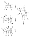
Figure 1 shows in side view a simple form of a first embodiment of a fastener useful in association with the combination of the invention, in fixed configuration; -
Figure 2 shows the fastener ofFigure 1 in the released configuration; -
Figure 3 shows the embodiment ofFigure 1 in rear view; -
Figure 4 shows a second embodiment of a fastener in linear form; -
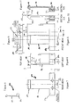
Figure 5 is a side view of a third embodiment of a fastener; -
Figure 6 is an enlarged form of the embodiment inFigure 5 ; -
Figure 7 is a rear view of the embodiment ofFigure 6 ; -
Figure 8 is a front view of the embodiment ofFigure 6 ; -
Figure 9 is a top view of the embodiment ofFigure 6 ; -
Figure 10 is a sectional view along the lines A-A ofFigure 8 ; -
Figure 11 is a sectional view along the lines B-B ofFigure 8 ; -
Figure 12 shows in reduced form the embodiment ofFigures 13-18 ; -
Figure 13 is a side view of the embodiment ofFigure 12 , designed for "intelligent" use; -
Figure 14 is a top view of the embodiment inFigure 12 ; -
Figure 15 is a bottom view of the embodiment inFigure 12 ; -
Figure 16 is a front view of the embodiment ofFigure 12 ; -
Figure 17 is a sectional view taken along the lines A-A ofFigure 16 ; -
Figure 18 is a sectional view taken along the lines B-B ofFigure 16 ; -
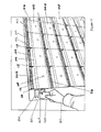
Figure 19 shows an embodiment of an array of mail boxes capable of being operated by use of a smart card; -
Figure 20 shows the mail boxes ofFigure 19 with one of the mail boxes indicating visually a status of the closure and also illustrating communication with two remote devices; and -
Figure 21 is a similar view to that inFigure 20 but illustrating a visual indication of different status and a different communication to those inFigure 20 . - Referring first to
Figures 1 to 3 , the fastener indicated generally at 10 is principally made of suitable deformable material inshank 12 andhook 14. Titanium/nickel shapedmemory wire 16 connects the top ofhook 14 withbase 18.Base 18 is shown mounted in anappropriate recess 20 retainingfastener 10 in position.Base 18 hasterminals 22 and 24 connected to an electric power supply (not shown).Wire 14 may be suitably insulated to improve performance (insulation not shown). -
Fastener 10 takes the form of an overhang clip which, inFigure 1 , is shown in the firstposition engaging clip 26 being formed integrally withelement 28,base 18 ofoverhang clip 10 being restrained by the shape ofrecess 20 in anotherelement 30. - In
Figure 2 ,wire 16 has been heated by the application of power viaterminals 22 and 24 inbase 18.Wire 16 has contracted, causinghook 14 to be drawn away from contact withhook 26. The separation betweenhook 14 andhook 26 is somewhat exaggerated inFigure 2 for convenience of illustration. Ifwire 16 is permitted to cool, for example by suitable reduction in power being applied viaterminals 22 and 24,overhang hook 10 can return to the state shown inFigure 1 and re-engagehook 26. - Turning now to
Figure 4 , parts which are similar to those inFigures 1 to 3 carry the same numerals. In this embodiment,linear overhang hook 40 hasshank 12,hook 14 andbase 18. Shape memory wire (not shown) is integrated withoverhang hook 40. Also included are positive andnegative buses 42 and 44, connecting by metal wire lashing 46.Overhang hook 40 is especially suitable for providing a continuous form of fastener - Turning now to the embodiment in
Figures 5 to 11 , once again, the same numerals will be used for similar parts as in the embodiment inFigures 1 to 3 . Except forbase 32,overhang fastener 50 is very similar to that inFigures 1 to 3 . No shape memory wire is shown in the embodiment inFigures 5 to 11 but of course it is included. As may be seen fromFigures 9 and 10 ,vertical holes 34 are included inbase 32.Base 32 also includes horizontal cavity 36. The purpose ofholes 34 and cavity 36 is to accommodate screws. - With reference now to
Figures 12 to 18 , overhang fastener 60 hasshank 12 andhook 14, similarly to previous embodiments. However,base 62, which contains cutouts 64 either side of bridge 66 (referFigure 15 ) includes cavity 68 designed to receive a microprocessor or connect to a circuit board so that fastener 60 can be "addressable". A reduced scale version of fastener 60 is shown inFigure 12 . - Turning now to
Figure 19 , this shows a number ofmail boxes 100 set out in a rectangular array. Eachmail box 100 has aletter slot 102 and anarea 104 onclosure 106 for insertion of detail such as the number of the box or the name of the owner, etc.Closure 106 also includes LED 108 for indicating status ofclosure 106 or the compartment within. The compartment has anopening 110, of whichletter slot 102 forms part.Opening 110 is defined bycompartment walls Figure 19 ). -
Card reader 120 is mounted onside wall 122 of the array ofmail boxes 100. When auser 126 passessmart card 124 in front ofcard reader 120,card reader 120 reads information stored onsmart card 124 and, if appropriate, addresses the fastener or fasteners (not shown) in the appropriate mail box. In this embodiment, it will be assumed that the appropriate mail box is 100A.Card reader 120 then causes an electrical current to be passed through a multi-drop communications and power feed bus connecting all themail boxes 100. The fastener or fasteners on mail box 100A are addressed, sufficient current is applied to cause shape memory alloy in the fastener or fasteners to contract causing the fastener or fasteners to release andclosure 106 to open. LED 108 may be unlit to show thatclosure 106 is properly closingopening 110 onmail box 100. Alternately, LED 108 may be assigned a particular colour, such as green, when in this situation. In the case of mail box 100A, once the fastener has caused the closure to open, LED 108, connected to the fastener or fasteners, may emit a red colour to indicate that the status of mail box 100A is "open". - It should also be mentioned that LED 108 may emit a different colour, such as blue, to indicate that there is mail within
mail box 100. -
Smart card 124 is shown having an endorsement 128 as to a particular amount of currency. If the array ofmail boxes 100 represents private mail boxes operated by a private enterprise for profit, a user may be assigned a particular mail box 100 (such as mail box 100A) and be givensmart card 124 upon payment of the appropriate fee (in this case, $25.00).Smart card 124 may be programmed to expire after a particular period or once a particular date is reached. Alternately,smart card 124 may be configured so that a small fee is deducted fromsmart card 124 each time it is read bycard reader 120. The fee may be deducted against a credit onsmart card 124 or from an authorised bank account. More frequent operation of mail box 100A will use up the credit onsmart card 124 more quickly. If LED 108 shows whether the compartment in mail box 100A is empty or not, unnecessary opening of mail box 100A is eliminated, thus maximising the value to be obtained fromsmart card 124. -
Smart card 124 may have multiple uses. For example, it may be programmed to open the door of a condominium, or it may also operate as a credit card. - With reference now to
Figure 20 , where the same numerals as inFigure 19 are used for the same parts,mail box 100B is shown withcrowbar 130 inserted so as to forceopen closure 106. LED 108 is emitting a chosen colour, such as red, to indicate that tampering has taken place or merely thatclosure 106 is in the open status. At the same time, a message has been transmitted to either or bothcomputer 132 andmobile phone 134. The signal can be sent frommail box 100B using known technology. It may be received oncomputer 132 via email and onmobile phone 134 via a text message. In the case ofcomputer 132, the email is shown indisplay 136. In the case ofmobile phone 134, the text message is shown indisplay 138. - In
Figure 21 , the same numerals are used as in the case ofFigures 19 and20 . InFigure 21 , mail 140 is inserted inletter slot 102, a fastener (not shown) withinmail box 100B or some other means senses the presence ofmail 140 and causes LED 108 to emit a chosen colour, such as blue. At the same time, LED 108 transmits a message by email tocomputer 132 or by a text message tomobile phone 134.Computer 132 displays the message that mail has been received ondisplay 136.Mobile phone 134 displays a similar message ondisplay 138. - If
mail 140 carries a suitable readable tag, such as a radio frequency identification tag the nature of that mail may be messaged tocomputer 132 and/ormobile phone 134, as appropriate.Computer 132 may of course be a hand-held computer carried by a courier, so that the courier can receive acknowledgment of the delivery of the mail. - The invention in its various aspects can greatly improve efficiency and lower costs in relation to compartments, especially mail boxes and lockers. The invention can save unnecessary labour, it can save time and it can enable economic benefits in the operation of commercial mail boxes and lockers.
- It will be apparent that many other versions of the invention may be devised within the scope of the claims.
Claims (38)
- A combination, the combination comprising:a compartment having one or more walls and an opening (110) defined by at least one of the walls (112, 114, 116, 118);a closure (106);at least one fastener co-operable with the closure and adapted to hold the closure in a first position relative to the opening; andwherein the combination forms an array with other combinations, each other combination having at least one similar fastener;characterised in that,the closure (106) includes at least one indicium (108) visible from outside the compartment and adapted to provide a visual indication of a status of the closure (106); andthe at least one fastener is adapted to cause the closure (106) to assume a second position relative to the opening (110) upon receipt of a suitable signal, wherein the at least one fastener is addressable and the signal is provided by means external to the compartment and capable of addressing the at least one fastener in the array of compartments, wherein the status of the closure indicated by the indicium is whether the closure (106) is in the first position or the second position.
- The combination of claim 1, wherein the at least one fastener includes means for communicating to a remote device information relating to the closure (106), the compartment or its contents.
- The combination of claim 1 or 2, wherein the compartment is a mail box or locker.
- The combination of claim 3, wherein the compartment is a mail box having an internal opening for deposit of mail.
- The combination of any one of claims 1-4, the closure having a slot provided at one end of or through the closure (106).
- The combination of any one of claims 1-5, wherein the closure (106) is hinged to the compartment at the opening (110).
- The combination of any one of claims 1-6, wherein in the first position the closure (106) closes the opening (110).
- The combination of claim 7, wherein the at least one fastener located inside the compartment is adapted to hold the closure (106) in the first position relative to the opening (110) without input of energy.
- The combination of any one of claims 1-8, wherein in the second position the closure permits access to the opening (110) upon receipt of the signal.
- The combination of any one of claims 1-9, wherein the at least one fastener includes a fastening element having a flexible beam and an engagement means; and actuating means attached to the fastener and including a material adapted to contract when activated; the beam being moveable, upon contraction of the material, between an engagement position and a disengagement position.
- The combination of claim 10, wherein the material adapted to contract when activated is chosen from the group; shape memory wire, shape memory strip and shape memory alloy in sputter form.
- The combination of claim 10 or 11, which includes two of the actuating means attached to the fastening element.
- The combination of claim 12, wherein one of the actuating means is adapted to cause the beam to move to the disengagement position and the other actuating means is adapted to cause the beam to move to the engagement position.
- The combination of any one of claims 1-9, wherein the at least one fastener is a fastener assembly for releasably securing an element, the element including a post having a groove, the assembly including a bar adapted to engage the groove to secure the element, the assembly also including a connecting means attached to the bar and consisting of or including shape memory material which, upon application of suitable energy, is adapted to change shape and draw the bar out of engagement with the groove thus releasing the element.
- The combination of claim 14, wherein the element has more than one post, each having a groove.
- The combination of claim 15, wherein the bar is adapted to engage the groove in more than one post.
- The combination of any one of claims 14-16, wherein the shape memory material is a titanium-nickel wire and the suitable energy is heat.
- The combination of any one of claims 1-17, wherein the at least one fastener is adapted to cause the closure (106) to assume the second position relative to the opening (110) by releasing the closure (106), the closure (106) adapted to fall open under the influence of gravity.
- The combination of any one of claims 1-18, wherein the closure (106) is adapted to return to the first position from the second position by the application of pressure of the closure (106) against the opening.
- The combination of any one of claims 1-19, the closure (106) being co-operable with two or more fasteners.
- The combination of any one of claims 1-20, wherein each fastener is located on the closure (106).
- The combination of any one of claims 1-20, wherein each fastener is located on a wall (112, 114, 116, 118) of the compartment.
- The combination of claim 1, where there is more than one fastener associated with the closure, but only one fastener is addressable.
- The combination of claim 1 or 23, wherein at least one fastener is encrypted.
- The combination of claim 1, wherein the indicium further shows whether the compartment contains contents or is empty.
- The combination of claim 1 or 25, wherein the indicium (108) takes a form of one or more light emitting diode (108) chips.
- The combination of claim 26, wherein the at least one fastener is linked to the light emitting diode (108) chip or chips.
- The combination as claimed in claim 1, wherein the at least one fastener is adapted to read information on an article located inside the compartment and to communicate information regarding the article to the remote device.
- The combination as claimed in claim 1 or 28, wherein the remote device is a computer and the means for communicating is adapted to communicate by email to the computer.
- The combination as claimed in claim 1 or 28, wherein the remote device is a mobile phone and the means for communicating is adapted to communicate a text message to the mobile phone.
- The combination of claim 2, wherein the information relates to status of the closure (106) and is chosen from the group being closure open, closure closed and closure damaged.
- The combination of claim 2, wherein the information relates to status of the compartment and is chosen from the group: compartment empty, compartment occupied, compartment occupied by dangerous contents.
- The combination of claim 1, wherein the array comprises a smart card reader (120).
- The combination of claim 33, wherein the fasteners are connected in series.
- The combination of claim 33 or 34, wherein each fastener is addressable on an individual basis or as part of a group.
- The combination of claim 33, wherein the smart card reader (120) is arranged to deduct a fee each time a smart card (124) is read by the smart card reader.
- The combination of claim 36, wherein the smart card reader (120) is arranged to deduct the fee against a credit on the smart card (124) or from a remote account.
- The combination of claim 36 or 37, wherein the smart card (124) is adapted to open another closure and/or to operate as a credit card.
Priority Applications (1)
| Application Number | Priority Date | Filing Date | Title |
|---|---|---|---|
| PL04721087T PL1608250T3 (en) | 2003-03-17 | 2004-03-17 | A combination, comprising a compartment, a closure, and at least one fasterner, the combination forming an array with other combinations |
Applications Claiming Priority (3)
| Application Number | Priority Date | Filing Date | Title |
|---|---|---|---|
| AU2003901194 | 2003-03-17 | ||
| AU2003901194A AU2003901194A0 (en) | 2003-03-17 | 2003-03-17 | Closure for a compartment |
| PCT/AU2004/000319 WO2004082444A1 (en) | 2003-03-17 | 2004-03-17 | Closure for a compartment |
Publications (3)
| Publication Number | Publication Date |
|---|---|
| EP1608250A1 EP1608250A1 (en) | 2005-12-28 |
| EP1608250A4 EP1608250A4 (en) | 2007-07-18 |
| EP1608250B1 true EP1608250B1 (en) | 2014-03-05 |
Family
ID=31500238
Family Applications (1)
| Application Number | Title | Priority Date | Filing Date |
|---|---|---|---|
| EP04721087.7A Expired - Lifetime EP1608250B1 (en) | 2003-03-17 | 2004-03-17 | A combination, comprising a compartment, a closure, and at least one fasterner, the combination forming an array with other combinations |
Country Status (6)
| Country | Link |
|---|---|
| US (3) | US7878389B2 (en) |
| EP (1) | EP1608250B1 (en) |
| AU (1) | AU2003901194A0 (en) |
| ES (1) | ES2468218T3 (en) |
| PL (1) | PL1608250T3 (en) |
| WO (1) | WO2004082444A1 (en) |
Families Citing this family (38)
| Publication number | Priority date | Publication date | Assignee | Title |
|---|---|---|---|---|
| GB9811377D0 (en) | 1998-05-27 | 1998-07-22 | Isis Innovations Ltd | Compositions |
| AUPQ861300A0 (en) | 2000-07-06 | 2000-08-03 | Telezygology Pty Limited | Mulit-function tool |
| US7600301B2 (en) | 2002-06-19 | 2009-10-13 | Telezygology, Inc. | Fixing and release systems and fastener networks |
| CN104132043B (en) | 2003-11-17 | 2017-04-12 | 远程接合技术公司 | Fasteners and other assemblies |
| EP1774183A4 (en) * | 2004-03-16 | 2009-06-03 | Telezygology Inc | SIGNAL-ACTIVATED MOUNTING ELEMENT ASSEMBLY |
| WO2005090798A1 (en) * | 2004-03-16 | 2005-09-29 | Telezygology Inc. | Fastener networks |
| US7128295B2 (en) * | 2005-01-07 | 2006-10-31 | The Boeing Company | Pivot mechanism for quick installation of stowage bins or rotating items |
| US20080231154A1 (en) * | 2005-01-20 | 2008-09-25 | Telezygology, Inc. | Locking Systems |
| JP2006277199A (en) * | 2005-03-29 | 2006-10-12 | Fujitsu Ltd | Delivery management system and delivery storage |
| EP1931885B1 (en) * | 2005-10-04 | 2011-07-06 | Telezygology Inc. | Electronic communication system |
| EP1960676A4 (en) * | 2005-12-12 | 2010-06-02 | Telezygology Inc | DASHBOARD |
| US10909789B2 (en) | 2006-05-31 | 2021-02-02 | Digilock Asia Ltd. | Electronic cam lock for cabinet doors, drawers and other applications |
| US8490443B2 (en) * | 2006-05-31 | 2013-07-23 | Security People, Inc. | Electronic lock for cabinet doors, drawers and other applications |
| US7893645B2 (en) * | 2006-08-25 | 2011-02-22 | The Boeing Company | System and method for compartment control |
| US7723935B2 (en) * | 2006-08-25 | 2010-05-25 | The Boeing Company | System and method for compartment control |
| US20080078871A1 (en) * | 2006-08-25 | 2008-04-03 | The Boeing Company | System and method for electronically latching compartments |
| USD562779S1 (en) | 2006-08-25 | 2008-02-26 | The Boeing Company | Electronic interactive switch |
| US7887008B2 (en) * | 2006-08-25 | 2011-02-15 | The Boeing Company | System and method for a power-assisted compartment |
| US20080055836A1 (en) * | 2006-08-25 | 2008-03-06 | The Boeing Company | System and method for compartment control |
| US7937169B2 (en) * | 2006-08-25 | 2011-05-03 | The Boeing Company | System and method for compartment control |
| US7762737B2 (en) | 2006-11-09 | 2010-07-27 | The Boeing Company | System and method for stowage compartment pivot assembly |
| US7876199B2 (en) * | 2007-04-04 | 2011-01-25 | Motorola, Inc. | Method and apparatus for controlling a skin texture surface on a device using a shape memory alloy |
| US8761846B2 (en) * | 2007-04-04 | 2014-06-24 | Motorola Mobility Llc | Method and apparatus for controlling a skin texture surface on a device |
| EP2609268B1 (en) * | 2010-08-27 | 2019-10-09 | Telezygology Inc. | Locking system |
| CN102835885A (en) * | 2011-06-24 | 2012-12-26 | 苏州唯亚管理咨询有限公司 | Intelligent mailbox |
| DE102012007678B4 (en) * | 2012-04-17 | 2019-07-04 | Diehl Aviation Laupheim Gmbh | Luggage compartment for an airplane |
| WO2013169114A1 (en) * | 2012-05-07 | 2013-11-14 | Postlogi | Mail delivery system and method for the delivery of mail items to such a mail delivery system |
| US10694874B2 (en) * | 2013-03-08 | 2020-06-30 | Sealy Technology, Llc | Latex foam pillow |
| AU2014237417B2 (en) | 2013-03-15 | 2016-05-12 | Assa Abloy Americas Residential Inc. | Wireless lockset with integrated antenna, touch activation and light communication device |
| JP6153364B2 (en) * | 2013-03-29 | 2017-06-28 | グローリー株式会社 | Article storage apparatus and article storage method |
| CN105378195B (en) | 2013-07-12 | 2018-04-17 | Invue安全产品公司 | For the merchandise security devices being used together with electron key |
| JP2015089441A (en) * | 2013-11-06 | 2015-05-11 | 株式会社西電通 | Mail box system |
| US9422745B2 (en) * | 2014-05-09 | 2016-08-23 | Leslie Ho Leung Chow | Safe with nitinol wire locking mechanism |
| CA3017635A1 (en) | 2016-03-22 | 2017-09-28 | Spectrum Brands, Inc. | Garage door opener with touch sensor authentication |
| NO342226B1 (en) * | 2016-09-23 | 2018-04-23 | Postlogi As | Item delivery system, a method of delivering to and fetching mail from a mail box, and a software product. |
| US10815698B2 (en) * | 2017-10-02 | 2020-10-27 | William Henricks | Temporary locking storage container, system and method to reduce electronic device distraction in a group setting |
| US11450158B2 (en) | 2018-01-05 | 2022-09-20 | Spectrum Brands, Inc. | Touch isolated electronic lock |
| CN114518019A (en) * | 2022-03-25 | 2022-05-20 | 昆山德辉泰工业设备有限公司 | Automatic door oven |
Family Cites Families (30)
| Publication number | Priority date | Publication date | Assignee | Title |
|---|---|---|---|---|
| FR2563987B1 (en) | 1984-05-10 | 1986-10-17 | Lille Sa Distr Gde Brasserie | TELEMATIC CHIP BOX |
| FR2644916B1 (en) * | 1989-03-23 | 1993-01-22 | Mors | STORAGE SYSTEM WITH ADJACENT LOCKERS CONTROLLED BY A MICROPROCESSOR DEVICE |
| US5108214A (en) * | 1991-06-13 | 1992-04-28 | The United States Of America As Represented By The Administrator Of The National Aeronautics And Space Administration | Coupling device with improved thermal interface |
| FR2687298A1 (en) * | 1992-02-19 | 1993-08-20 | Boniface Andre | System for indicating that an object has been placed in a closed chamber such as a letterbox, and chamber, such as a letterbox, equipped with such a system |
| CA2098973A1 (en) * | 1993-06-22 | 1994-12-23 | Enn Kaarsoo | Electroic access control mail box system |
| DE4327381C2 (en) * | 1993-08-14 | 2001-07-05 | Univ Dresden Tech | Detachable connecting element |
| JPH0811984A (en) * | 1994-07-05 | 1996-01-16 | Mitsubishi Denki Bill Techno Service Kk | Delivery storage locker device |
| JP3619549B2 (en) * | 1994-09-22 | 2005-02-09 | 美和ロック株式会社 | Locking and unlocking device for mechanical lock |
| US5774053A (en) | 1996-05-02 | 1998-06-30 | Porter; David | Storage device for the delivery and pickup of goods |
| JPH09317278A (en) * | 1996-05-27 | 1997-12-09 | Alpha Corp | Non-contact rocker system |
| JPH10257960A (en) * | 1997-03-18 | 1998-09-29 | Topy Ind Ltd | Delivery box device and delivery system |
| JPH1118916A (en) | 1997-07-04 | 1999-01-26 | Matsushita Electric Ind Co Ltd | Parcel delivery system |
| US5850967A (en) * | 1998-02-26 | 1998-12-22 | White; J. La Nell | Security mailbox |
| AUPP247798A0 (en) | 1998-03-18 | 1998-04-23 | Rudduck, Dickory | Fixing and release systems |
| US6028517A (en) * | 1998-12-23 | 2000-02-22 | Pitney Bowes Inc. | Status indicating system for indicating the deposit and withdrawal of items in a receptacle |
| JP2001015956A (en) * | 1999-06-30 | 2001-01-19 | Nec Corp | Disconnecting method and connection structure between housing of electronic device and mounted component, and electronic device |
| WO2001015579A1 (en) * | 1999-09-01 | 2001-03-08 | Greatworth Ltd. | Secure article delivery apparatus and method |
| US20010045449A1 (en) * | 2000-01-31 | 2001-11-29 | Shannon Bruce L. | Internet delivery lock box |
| JP2001243575A (en) * | 2000-02-28 | 2001-09-07 | Full Time System:Kk | Alarm system using home delivery lockers |
| JP2002017554A (en) * | 2000-07-07 | 2002-01-22 | Full Time System:Kk | User notification system for home delivery lockers |
| JP2002034772A (en) * | 2000-07-26 | 2002-02-05 | Matsushita Electric Works Ltd | Delivery notification system |
| US6412688B1 (en) * | 2000-08-24 | 2002-07-02 | Solar Group, Inc. | Secure parcel receptacle, lock assembly therefore and associated method |
| WO2002066344A1 (en) * | 2001-02-20 | 2002-08-29 | United States Postal Service | Universal delivery and collection box unit (udcbu) |
| US6483433B2 (en) * | 2001-02-20 | 2002-11-19 | International Business Machines Corporation | Method and apparatus for notifying of receipt |
| US6995671B2 (en) * | 2002-01-15 | 2006-02-07 | International Business Machines Corporation | Mailbox status system and method |
| US7600301B2 (en) * | 2002-06-19 | 2009-10-13 | Telezygology, Inc. | Fixing and release systems and fastener networks |
| AUPS312302A0 (en) | 2002-06-19 | 2002-07-18 | Telezygology Inc | Further improvements in fixing and release systems |
| JP5110617B2 (en) | 2002-07-22 | 2012-12-26 | テレズィゴロジー インク | Fasteners for assembly and disassembly |
| US6995674B2 (en) * | 2003-02-28 | 2006-02-07 | Saxon, Inc. | Package assembly |
| US7256691B2 (en) * | 2004-05-12 | 2007-08-14 | Christopher Awobue | Smart mailbox |
-
2003
- 2003-03-17 AU AU2003901194A patent/AU2003901194A0/en not_active Abandoned
-
2004
- 2004-03-17 ES ES04721087.7T patent/ES2468218T3/en not_active Expired - Lifetime
- 2004-03-17 US US10/549,485 patent/US7878389B2/en not_active Expired - Fee Related
- 2004-03-17 EP EP04721087.7A patent/EP1608250B1/en not_active Expired - Lifetime
- 2004-03-17 PL PL04721087T patent/PL1608250T3/en unknown
- 2004-03-17 WO PCT/AU2004/000319 patent/WO2004082444A1/en not_active Ceased
-
2010
- 2010-12-20 US US12/972,739 patent/US8360307B2/en not_active Expired - Fee Related
-
2012
- 2012-12-09 US US13/709,007 patent/US9546512B2/en not_active Expired - Fee Related
Also Published As
| Publication number | Publication date |
|---|---|
| US20110276472A1 (en) | 2011-11-10 |
| US20060097034A1 (en) | 2006-05-11 |
| US7878389B2 (en) | 2011-02-01 |
| US9546512B2 (en) | 2017-01-17 |
| US8360307B2 (en) | 2013-01-29 |
| WO2004082444A1 (en) | 2004-09-30 |
| EP1608250A1 (en) | 2005-12-28 |
| US20140040115A1 (en) | 2014-02-06 |
| AU2003901194A0 (en) | 2003-04-03 |
| EP1608250A4 (en) | 2007-07-18 |
| ES2468218T3 (en) | 2014-06-16 |
| PL1608250T3 (en) | 2014-08-29 |
Similar Documents
| Publication | Publication Date | Title |
|---|---|---|
| US9546512B2 (en) | Closure for a compartment | |
| US6769611B2 (en) | Method and apparatus for the secure delivery of goods | |
| WO2001000069A2 (en) | Postal box | |
| US20070296545A1 (en) | System for management of ubiquitously deployed intelligent locks | |
| US20030079129A1 (en) | Secure delivery or collection system | |
| EP4217977A1 (en) | Reusable delivery container and delivery system | |
| US20040053641A1 (en) | System and method for delivery to multiple units | |
| KR100917718B1 (en) | Access control system and method using smart tag | |
| GB2371833A (en) | An electromechanical valve assembly for an i.c. engine | |
| ES2296636T3 (en) | APPARATUS AND METHOD OF SAFE DELIVERY OF ARTICLES. | |
| GB2353068A (en) | Postal box | |
| RU97552U1 (en) | REMOTE SALES SYSTEM | |
| RU121622U1 (en) | STORAGE CHAMBER OF DELIVERED ORDERS | |
| CN207976947U (en) | A kind of Intelligent cargo cabinet | |
| DE202007000731U1 (en) | Delivery and / or supplier box and their closing device | |
| KR101474169B1 (en) | Delivery service receiving system | |
| JP2000079052A (en) | Delivery box that can handle registered mail | |
| CN210605849U (en) | Multifunctional intelligent digital management control device and intelligent management control device | |
| US20060151615A1 (en) | Radio identifiable mark | |
| CN107886628A (en) | A kind of vending system of automatic selling cabinet | |
| JP2006127237A (en) | Automatic vending machine | |
| JP2002068427A (en) | Product delivery system | |
| KR20030052675A (en) | Home Delivery Freight Deposit Management System | |
| GB2375137A (en) | Security locking system with printer | |
| JP2025062421A (en) | Admission management system and admission management method |
Legal Events
| Date | Code | Title | Description |
|---|---|---|---|
| PUAI | Public reference made under article 153(3) epc to a published international application that has entered the european phase |
Free format text: ORIGINAL CODE: 0009012 |
|
| 17P | Request for examination filed |
Effective date: 20051013 |
|
| AK | Designated contracting states |
Kind code of ref document: A1 Designated state(s): AT BE BG CH CY CZ DE DK EE ES FI FR GB GR HU IE IT LI LU MC NL PL PT RO SE SI SK TR |
|
| AX | Request for extension of the european patent |
Extension state: AL LT LV MK |
|
| DAX | Request for extension of the european patent (deleted) | ||
| A4 | Supplementary search report drawn up and despatched |
Effective date: 20070620 |
|
| 17Q | First examination report despatched |
Effective date: 20071031 |
|
| RAP1 | Party data changed (applicant data changed or rights of an application transferred) |
Owner name: TELEZYGOLOGY INC. |
|
| GRAP | Despatch of communication of intention to grant a patent |
Free format text: ORIGINAL CODE: EPIDOSNIGR1 |
|
| INTG | Intention to grant announced |
Effective date: 20130924 |
|
| RAP1 | Party data changed (applicant data changed or rights of an application transferred) |
Owner name: TELEZYGOLOGY INC. |
|
| GRAS | Grant fee paid |
Free format text: ORIGINAL CODE: EPIDOSNIGR3 |
|
| GRAA | (expected) grant |
Free format text: ORIGINAL CODE: 0009210 |
|
| AK | Designated contracting states |
Kind code of ref document: B1 Designated state(s): AT BE BG CH CY CZ DE DK EE ES FI FR GB GR HU IE IT LI LU MC NL PL PT RO SE SI SK TR |
|
| REG | Reference to a national code |
Ref country code: GB Ref legal event code: FG4D |
|
| REG | Reference to a national code |
Ref country code: CH Ref legal event code: EP |
|
| REG | Reference to a national code |
Ref country code: AT Ref legal event code: REF Ref document number: 654271 Country of ref document: AT Kind code of ref document: T Effective date: 20140315 |
|
| REG | Reference to a national code |
Ref country code: IE Ref legal event code: FG4D |
|
| REG | Reference to a national code |
Ref country code: DE Ref legal event code: R096 Ref document number: 602004044511 Country of ref document: DE Effective date: 20140410 |
|
| REG | Reference to a national code |
Ref country code: ES Ref legal event code: FG2A Ref document number: 2468218 Country of ref document: ES Kind code of ref document: T3 Effective date: 20140616 |
|
| REG | Reference to a national code |
Ref country code: AT Ref legal event code: MK05 Ref document number: 654271 Country of ref document: AT Kind code of ref document: T Effective date: 20140305 |
|
| REG | Reference to a national code |
Ref country code: NL Ref legal event code: VDEP Effective date: 20140305 |
|
| PG25 | Lapsed in a contracting state [announced via postgrant information from national office to epo] |
Ref country code: CY Free format text: LAPSE BECAUSE OF FAILURE TO SUBMIT A TRANSLATION OF THE DESCRIPTION OR TO PAY THE FEE WITHIN THE PRESCRIBED TIME-LIMIT Effective date: 20140305 Ref country code: FI Free format text: LAPSE BECAUSE OF FAILURE TO SUBMIT A TRANSLATION OF THE DESCRIPTION OR TO PAY THE FEE WITHIN THE PRESCRIBED TIME-LIMIT Effective date: 20140305 Ref country code: SE Free format text: LAPSE BECAUSE OF FAILURE TO SUBMIT A TRANSLATION OF THE DESCRIPTION OR TO PAY THE FEE WITHIN THE PRESCRIBED TIME-LIMIT Effective date: 20140305 Ref country code: AT Free format text: LAPSE BECAUSE OF FAILURE TO SUBMIT A TRANSLATION OF THE DESCRIPTION OR TO PAY THE FEE WITHIN THE PRESCRIBED TIME-LIMIT Effective date: 20140305 |
|
| REG | Reference to a national code |
Ref country code: PL Ref legal event code: T3 |
|
| PG25 | Lapsed in a contracting state [announced via postgrant information from national office to epo] |
Ref country code: NL Free format text: LAPSE BECAUSE OF FAILURE TO SUBMIT A TRANSLATION OF THE DESCRIPTION OR TO PAY THE FEE WITHIN THE PRESCRIBED TIME-LIMIT Effective date: 20140305 Ref country code: CZ Free format text: LAPSE BECAUSE OF FAILURE TO SUBMIT A TRANSLATION OF THE DESCRIPTION OR TO PAY THE FEE WITHIN THE PRESCRIBED TIME-LIMIT Effective date: 20140305 Ref country code: EE Free format text: LAPSE BECAUSE OF FAILURE TO SUBMIT A TRANSLATION OF THE DESCRIPTION OR TO PAY THE FEE WITHIN THE PRESCRIBED TIME-LIMIT Effective date: 20140305 Ref country code: RO Free format text: LAPSE BECAUSE OF FAILURE TO SUBMIT A TRANSLATION OF THE DESCRIPTION OR TO PAY THE FEE WITHIN THE PRESCRIBED TIME-LIMIT Effective date: 20140305 Ref country code: BG Free format text: LAPSE BECAUSE OF FAILURE TO SUBMIT A TRANSLATION OF THE DESCRIPTION OR TO PAY THE FEE WITHIN THE PRESCRIBED TIME-LIMIT Effective date: 20140605 Ref country code: BE Free format text: LAPSE BECAUSE OF FAILURE TO SUBMIT A TRANSLATION OF THE DESCRIPTION OR TO PAY THE FEE WITHIN THE PRESCRIBED TIME-LIMIT Effective date: 20140305 |
|
| REG | Reference to a national code |
Ref country code: CH Ref legal event code: PL |
|
| PG25 | Lapsed in a contracting state [announced via postgrant information from national office to epo] |
Ref country code: SK Free format text: LAPSE BECAUSE OF FAILURE TO SUBMIT A TRANSLATION OF THE DESCRIPTION OR TO PAY THE FEE WITHIN THE PRESCRIBED TIME-LIMIT Effective date: 20140305 |
|
| REG | Reference to a national code |
Ref country code: DE Ref legal event code: R097 Ref document number: 602004044511 Country of ref document: DE |
|
| PG25 | Lapsed in a contracting state [announced via postgrant information from national office to epo] |
Ref country code: PT Free format text: LAPSE BECAUSE OF FAILURE TO SUBMIT A TRANSLATION OF THE DESCRIPTION OR TO PAY THE FEE WITHIN THE PRESCRIBED TIME-LIMIT Effective date: 20140707 |
|
| REG | Reference to a national code |
Ref country code: IE Ref legal event code: MM4A |
|
| PLBE | No opposition filed within time limit |
Free format text: ORIGINAL CODE: 0009261 |
|
| STAA | Information on the status of an ep patent application or granted ep patent |
Free format text: STATUS: NO OPPOSITION FILED WITHIN TIME LIMIT |
|
| PG25 | Lapsed in a contracting state [announced via postgrant information from national office to epo] |
Ref country code: DK Free format text: LAPSE BECAUSE OF FAILURE TO SUBMIT A TRANSLATION OF THE DESCRIPTION OR TO PAY THE FEE WITHIN THE PRESCRIBED TIME-LIMIT Effective date: 20140305 Ref country code: MC Free format text: LAPSE BECAUSE OF FAILURE TO SUBMIT A TRANSLATION OF THE DESCRIPTION OR TO PAY THE FEE WITHIN THE PRESCRIBED TIME-LIMIT Effective date: 20140305 Ref country code: CH Free format text: LAPSE BECAUSE OF NON-PAYMENT OF DUE FEES Effective date: 20140331 Ref country code: LI Free format text: LAPSE BECAUSE OF NON-PAYMENT OF DUE FEES Effective date: 20140331 Ref country code: IE Free format text: LAPSE BECAUSE OF NON-PAYMENT OF DUE FEES Effective date: 20140317 |
|
| 26N | No opposition filed |
Effective date: 20141208 |
|
| REG | Reference to a national code |
Ref country code: DE Ref legal event code: R097 Ref document number: 602004044511 Country of ref document: DE Effective date: 20141208 |
|
| PG25 | Lapsed in a contracting state [announced via postgrant information from national office to epo] |
Ref country code: SI Free format text: LAPSE BECAUSE OF FAILURE TO SUBMIT A TRANSLATION OF THE DESCRIPTION OR TO PAY THE FEE WITHIN THE PRESCRIBED TIME-LIMIT Effective date: 20140305 |
|
| REG | Reference to a national code |
Ref country code: FR Ref legal event code: PLFP Year of fee payment: 13 |
|
| PG25 | Lapsed in a contracting state [announced via postgrant information from national office to epo] |
Ref country code: GR Free format text: LAPSE BECAUSE OF FAILURE TO SUBMIT A TRANSLATION OF THE DESCRIPTION OR TO PAY THE FEE WITHIN THE PRESCRIBED TIME-LIMIT Effective date: 20140606 |
|
| PG25 | Lapsed in a contracting state [announced via postgrant information from national office to epo] |
Ref country code: HU Free format text: LAPSE BECAUSE OF FAILURE TO SUBMIT A TRANSLATION OF THE DESCRIPTION OR TO PAY THE FEE WITHIN THE PRESCRIBED TIME-LIMIT; INVALID AB INITIO Effective date: 20040317 Ref country code: LU Free format text: LAPSE BECAUSE OF NON-PAYMENT OF DUE FEES Effective date: 20140317 Ref country code: TR Free format text: LAPSE BECAUSE OF FAILURE TO SUBMIT A TRANSLATION OF THE DESCRIPTION OR TO PAY THE FEE WITHIN THE PRESCRIBED TIME-LIMIT Effective date: 20140305 |
|
| REG | Reference to a national code |
Ref country code: FR Ref legal event code: PLFP Year of fee payment: 14 |
|
| REG | Reference to a national code |
Ref country code: FR Ref legal event code: PLFP Year of fee payment: 15 |
|
| PGFP | Annual fee paid to national office [announced via postgrant information from national office to epo] |
Ref country code: FR Payment date: 20190328 Year of fee payment: 16 Ref country code: PL Payment date: 20190226 Year of fee payment: 16 Ref country code: IT Payment date: 20190321 Year of fee payment: 16 |
|
| PGFP | Annual fee paid to national office [announced via postgrant information from national office to epo] |
Ref country code: ES Payment date: 20190425 Year of fee payment: 16 |
|
| PG25 | Lapsed in a contracting state [announced via postgrant information from national office to epo] |
Ref country code: FR Free format text: LAPSE BECAUSE OF NON-PAYMENT OF DUE FEES Effective date: 20200331 |
|
| PGFP | Annual fee paid to national office [announced via postgrant information from national office to epo] |
Ref country code: GB Payment date: 20210326 Year of fee payment: 18 |
|
| PGFP | Annual fee paid to national office [announced via postgrant information from national office to epo] |
Ref country code: DE Payment date: 20210329 Year of fee payment: 18 |
|
| REG | Reference to a national code |
Ref country code: ES Ref legal event code: FD2A Effective date: 20210802 |
|
| PG25 | Lapsed in a contracting state [announced via postgrant information from national office to epo] |
Ref country code: IT Free format text: LAPSE BECAUSE OF NON-PAYMENT OF DUE FEES Effective date: 20200317 |
|
| PG25 | Lapsed in a contracting state [announced via postgrant information from national office to epo] |
Ref country code: ES Free format text: LAPSE BECAUSE OF NON-PAYMENT OF DUE FEES Effective date: 20200318 |
|
| PG25 | Lapsed in a contracting state [announced via postgrant information from national office to epo] |
Ref country code: PL Free format text: LAPSE BECAUSE OF NON-PAYMENT OF DUE FEES Effective date: 20200317 |
|
| REG | Reference to a national code |
Ref country code: DE Ref legal event code: R119 Ref document number: 602004044511 Country of ref document: DE |
|
| GBPC | Gb: european patent ceased through non-payment of renewal fee |
Effective date: 20220317 |
|
| PG25 | Lapsed in a contracting state [announced via postgrant information from national office to epo] |
Ref country code: GB Free format text: LAPSE BECAUSE OF NON-PAYMENT OF DUE FEES Effective date: 20220317 Ref country code: DE Free format text: LAPSE BECAUSE OF NON-PAYMENT OF DUE FEES Effective date: 20221001 |