EP1608213B1 - Means for mounting agricultural equipment to a multi-purpose self-propelled straddle carrier - Google Patents
Means for mounting agricultural equipment to a multi-purpose self-propelled straddle carrier Download PDFInfo
- Publication number
- EP1608213B1 EP1608213B1 EP04720011.8A EP04720011A EP1608213B1 EP 1608213 B1 EP1608213 B1 EP 1608213B1 EP 04720011 A EP04720011 A EP 04720011A EP 1608213 B1 EP1608213 B1 EP 1608213B1
- Authority
- EP
- European Patent Office
- Prior art keywords
- girders
- main frame
- auxiliary frame
- frame
- auxiliary
- Prior art date
- Legal status (The legal status is an assumption and is not a legal conclusion. Google has not performed a legal analysis and makes no representation as to the accuracy of the status listed.)
- Expired - Lifetime
Links
- 238000003306 harvesting Methods 0.000 claims description 32
- 238000000034 method Methods 0.000 claims description 17
- 238000009434 installation Methods 0.000 claims description 8
- 235000013399 edible fruits Nutrition 0.000 claims description 7
- 238000006073 displacement reaction Methods 0.000 claims description 6
- 239000002184 metal Substances 0.000 claims description 4
- 230000013011 mating Effects 0.000 claims 1
- 210000003414 extremity Anatomy 0.000 description 8
- 230000008878 coupling Effects 0.000 description 6
- 238000010168 coupling process Methods 0.000 description 6
- 238000005859 coupling reaction Methods 0.000 description 6
- 230000002787 reinforcement Effects 0.000 description 6
- 238000003466 welding Methods 0.000 description 5
- 238000005507 spraying Methods 0.000 description 4
- 235000009754 Vitis X bourquina Nutrition 0.000 description 3
- 235000012333 Vitis X labruscana Nutrition 0.000 description 3
- 240000006365 Vitis vinifera Species 0.000 description 3
- 235000014787 Vitis vinifera Nutrition 0.000 description 3
- 238000010586 diagram Methods 0.000 description 3
- 238000003032 molecular docking Methods 0.000 description 3
- 230000003014 reinforcing effect Effects 0.000 description 3
- 210000001364 upper extremity Anatomy 0.000 description 3
- 239000000969 carrier Substances 0.000 description 2
- 230000007246 mechanism Effects 0.000 description 2
- 238000013138 pruning Methods 0.000 description 2
- 241001124569 Lycaenidae Species 0.000 description 1
- 240000007817 Olea europaea Species 0.000 description 1
- 235000002357 Ribes grossularia Nutrition 0.000 description 1
- 244000171263 Ribes grossularia Species 0.000 description 1
- 240000001890 Ribes hudsonianum Species 0.000 description 1
- 235000016954 Ribes hudsonianum Nutrition 0.000 description 1
- 235000001466 Ribes nigrum Nutrition 0.000 description 1
- 240000007651 Rubus glaucus Species 0.000 description 1
- 235000011034 Rubus glaucus Nutrition 0.000 description 1
- 235000009122 Rubus idaeus Nutrition 0.000 description 1
- 241000219094 Vitaceae Species 0.000 description 1
- 235000021028 berry Nutrition 0.000 description 1
- 239000000872 buffer Substances 0.000 description 1
- 230000000295 complement effect Effects 0.000 description 1
- 230000007423 decrease Effects 0.000 description 1
- 230000008021 deposition Effects 0.000 description 1
- 235000021021 grapes Nutrition 0.000 description 1
- 239000000463 material Substances 0.000 description 1
- 230000000284 resting effect Effects 0.000 description 1
- 238000003860 storage Methods 0.000 description 1
- 238000003971 tillage Methods 0.000 description 1
Images





Classifications
-
- A—HUMAN NECESSITIES
- A01—AGRICULTURE; FORESTRY; ANIMAL HUSBANDRY; HUNTING; TRAPPING; FISHING
- A01B—SOIL WORKING IN AGRICULTURE OR FORESTRY; PARTS, DETAILS, OR ACCESSORIES OF AGRICULTURAL MACHINES OR IMPLEMENTS, IN GENERAL
- A01B59/00—Devices specially adapted for connection between animals or tractors and agricultural machines or implements
- A01B59/06—Devices specially adapted for connection between animals or tractors and agricultural machines or implements for machines mounted on tractors
- A01B59/061—Devices specially adapted for connection between animals or tractors and agricultural machines or implements for machines mounted on tractors specially adapted for enabling connection or disconnection controlled from the driver's seat
- A01B59/063—Devices specially adapted for connection between animals or tractors and agricultural machines or implements for machines mounted on tractors specially adapted for enabling connection or disconnection controlled from the driver's seat the connection comprising longitudinally oriented tang-and-sheath elements
Definitions
- the present invention relates to means and a method for mounting agricultural equipment to a shelf-propelled multi-purpose straddle carrier.
- Such equipment may be of the type used for the cultivation, treatment and harvesting of fruit-bearing shrubs planted in rows.
- the straddle carrier comprises a main frame, provided with ground-engaging wheels and lifting means between the wheels and the main frame for raising and lowering said main frame with respect to the ground.
- the agricultural equipment comprises an auxiliary frame, suitable for detachable connection to the main frame by detachable connecting means.
- the mounting means comprise the auxiliary and main frames on the one hand, and a plurality of struts for sustaining the main frame on the ground when the auxiliary frame is separated from the main frame, on the other hand.
- Both the main frame and the auxiliary frames comprise two parallel and substantially horizontal beams or girders.
- the present invention may be used in straddle carriers intended particularly, but not exclusively, for the cultivation, treatment and harvesting of grapes.
- the invention will be described with respect to such use, it being understood that it is also applicable to machines used in the cultivation, treatment and harvesting of other fruit-bearing shrubs such as raspberry, gooseberry, blackcurrant, olive bushes, etc.
- Grape harvesters comprising a multi-purpose self-propelled straddle carrier and mounting means of the type defined in the preamble are well known in the art (e.g., from FR-A-2 536 949 and FR-A-2 554 668 ).
- the object of the present invention is therefore essentially to provide mounting means, of the type defined in the preamble, which allow rapid coupling and uncoupling of the two main and auxiliary frames in relation to each other.
- mounting equipment intended for installation on a multi-purpose self-propelled straddle carrier for the cultivation, treatment and harvesting of fruit-bearing shrubs planted in rows, said mounting means comprising:
- the mounting means may comprise one or more of the following features:
- a method for the mounting of equipment selected from a variety of various items onto a multi-purpose self-propelled straddle carrier for the cultivation, treatment and harvesting of fruit-bearing shrubs planted in rows said self-propelled straddle carrier comprising a main frame suitable for lifting and lowering and comprising a first pair of parallel and spaced girders, the equipment being supported by elongate supports when in a state of waiting prior to installation on the self-propelled straddle carrier, and comprising an auxiliary frame suitable for connection to the main frame by detachable connection means and comprising a second pair of girders, said method being characterised in that it comprises:
- the method may also comprise one or more of the following features:
- a self-propelled multi-purpose straddle carrier comprising a main frame 1, consisting essentially of two parallel and substantially horizontal girders 2 (not visible in Figure 1 , but at least one of them is clearly visible in Figures 2 , 4 , 7 , 10 , 11 , 12 , 13, 14 and 15 ).
- the girders 2 are bridged at their front section by at least one crosspiece, which together with the girders 2 forms a rigid carrying frame for supporting a driver's cab 3 and an power unit 4 such as a diesel engine, suitable for driving the hydraulic pumps and the electrical generator, producing the hydraulic and electrical energy necessary for operating the various electrical and hydraulic units on the self-propelled straddle carrier and the equipment mounted thereto.
- the main frame 1 is mounted on four ground-engaging wheels, i.e., two front driving wheels 5 and two rear wheels 6 (only one front wheel and one rear wheel are visible in Figure 1 ).
- Each front wheel 5 is supported by a mechanism 7, which constitutes both a lifting device and a steering device and has, for example, a structure such as that described in FR-A-2 551 014 .
- Each rear wheel 6 is supported by an articulated arm 8, comprising a stationary vertical part 8a fixed rigidly to one of the two girders 2 of the main frame 1 and extending downwards from the girder, and a pivotable part 8b connected via a horizontal pivot axis to the lower end of part 8a and extending almost horizontally therefrom to the rear of the carrier.
- the wheel 6 is mounted in the rear end of the section 8b of the arm 8.
- a hydraulic cylinder 9 is mounted substantially vertically between the part 8b of each arm 8 and the main frame 1, for pivoting part 8b of the arm 8 and of the corresponding wheel in a vertical plane when the cylinder is actuated. Accordingly, when activated selectively, the two hydraulic cylinders 9 and the two hydraulic cylinders provided within the lifting and steering devices 7 of the two front wheels 5, allow the main frame 1 to be raised and lowered with respect to the ground 10.
- the above-mentioned cylinders can also be used as inclination compensation means, when the self-propelled straddle carrier moves along a slope. It is also well known that at least two of the four wheels 5 and 6, and preferably all four wheels 5 and 6, are driving wheels, as rotative hydraulic motors 11 and 12 are incorporated into the hubs of these wheels.
- the main frame 1 carries a detachable auxiliary frame 13, connected to the main frame by detachable connection means described in greater detail below.
- the auxiliary frame 13 itself supports an equipment 14, mainly comprising in the example shown in Figure 1 a harvesting unit 15 and at least one bin or hopper 16, and preferably two tipper bins located on either side of the harvesting unit 15 for temporary storage of the grape bunches or grape berries harvested.
- the equipment 14 is shown only in phantom outlines, as it is well-known equipment and its detailed description is therefore not necessary for a good understanding of the present invention.
- the auxiliary frame 13 comprises essentially two parallel, substantially horizontal beams or girders 17, bridged at their front ends by a front crossbar 18 and at their rear ends by a rear crossbar 19.
- the spacing of the two girders of the auxiliary frame 13 corresponds to the spacing of the two girders 2 of the main frame 1.
- Each girder 17 of the auxiliary frame 13 has, at least along a substantial part of its length, a profiled structure in the form of an inverted U, dimensioned for receiving one of the two girders 2 of the main frame 1 by sliding, in a manner described in further detail below.
- Each girder 2 consists, for example, of a caisson girder having rectangular or square section.
- Each of the two crossbars 18 and 19 of the auxiliary frame 13 includes an upper horizontal crosspiece 18a or 19a and two legs 18b or 19b. Substantially in the middle of each of the two crosspieces 18a and 19a, a support mount 21 or 22 (respectively) is fixed for a front or rear support assembly (not shown), which allows the known mounting of a harvesting unit 15 in a hanging position.
- Each of the two legs 19b of the rear crossbar 19 is provided with a support 23, which in turn supports two journals 24 used as a pivot for one of the two tipper bins 16.
- the two legs 19b of the rear crossbar 19 are for example welded to the rear extremities of the two girders 17 of the auxiliary frame 13, such that the two girders 17 and the rear crossbar 19 form a unitary weld assembly.
- the front crossbar 18 constitutes another weld assembly, comprising at the lower end of each of its legs 18b a base plate 18c which can be bolted, for example by four bolts 25, to a support plate 26, which is welded to the upper surface 17a of the corresponding girder 17 in the front section thereof, as shown in Figure 3 .
- Each of the two girders 2 of the main frame 1 extends rearwardly beyond the articulated arms 8, and its free rear end can be inserted into the front end of the channel formed by the inverted U profiled structure of the corresponding girder 17 of the auxiliary frame 13. It then slides longitudinally into the interior of said channel, being guided by the lateral walls of the channel.
- the caisson girder in each girder 2 is ending at its free rear extremity in a corner-shaped structure 27 with lateral faces 28 converging backwards and upwards.
- each of the two inverted U profiled structures constituting the girders 17 of the auxiliary frame 13 has at its front section two lateral wings, which diverge both forwardly and downwardly, thus forming an entry convergence for the corner-shaped structure 27 at the rear end of the corresponding girder 2 of the main frame 1.
- the auxiliary frame comprises, adjacent the front end of each girder 17, an anti-friction device suitable for contacting the upper surface 2a of the caisson girder constituting the corresponding girder 2 of the main frame 1.
- each anti-friction device may consist of a roller 31 mounted for rotation about an axle 32 and having ends supported by the vertical walls of a casing or support housing 33.
- Each housing 33 is fixed, for example by welding, to the base-plate 18c of the two corresponding legs 18b of the front crossbar 18.
- Each roller 31 partly protrudes into the interior of the inverted U profiled structure of the corresponding girder 17 via slot-shaped openings, which are generally designated by reference 34 in Figures 3 and 5 and which are provided and vertically aligned in the base-plate 18c, the support plate 26 and the upper surface 17a of the corresponding profiled girder 17.
- each reinforcement structure 35 has a stop 36 attached thereto for cooperation with another stop 37 provided in the rear area of each of the two caisson profiles making up the girders 2 of the main frame 1, in order to define a stop position limiting the longitudinal displacement of the main frame 1 with respect to the auxiliary frame 3, when the girders 2 are introduced and slid longitudinally in the channel of the inverted U profiled structure within the two girders 17 of the auxiliary frame 13.
- the stops 36 and 37 also have a centring function, as shown below.
- Each of the two girders 2 in the main frame 1, and each of the two girders 17 in the auxiliary frame 13, comprise the following structure adjacent their rear ends: one girder a male, truncated cone part 38, the other a female truncated cone part 39 with a truncated cone receptacle 39a of a shape complementary to the male part 38, allowing that part to fit tightly into the female part 39.
- each of the two female parts 39 is attached to the rear end of the caisson girder of the corresponding girder 2 of the main frame 1, so that it is offset backwards and downwards with respect to the corner-shaped structure 27, the geometric axis of the truncated cone receptacle 39a of the female part 39 being orientated substantially vertically.
- Each male truncated cone part 38 is fixed rigidly to the reinforcing structure 35 of the inverted U profiled structure of the corresponding girder 17, in immediate proximity to the wall of the front end 41 of the reinforcing structure 35, so that the male truncated cone part 38 extends substantially vertically downwards from the reinforcing structure 35 and below it, and the upper end of the foremost generator line of said male truncated cone part 38 is aligned substantially vertically to the wall of the front end 41, as shown in Figure 5 .
- the two stops 37 may consist of vertical sheet metal plates bent into a V and fixed respectively, for example by welding, behind the female parts 39, as can be seen in Figures 2 and 4 .
- the two stops 36 may also consist of two vertical sheet metal plates bent into a V and fixed respectively, for example by welding, to the reinforcement structures 35 on the inverted U profiled structures of each of the two girders 17, so that they extend downwards behind the male truncated cone parts 38, at such a distance therefrom that, when the main frame 1 is in the above-mentioned stop position defined by the stops 36 and 37, each male truncated cone part 38 can fit firmly into the corresponding female part 39 through upward vertical displacement of the main frame 1 in relation to the auxiliary frame 13.
- the upper surface 2a of the caisson girder constituting the girder 2 in the main frame 1 should, in the area of its front end, have an opening or cavity 42 as can be seen in Figure 4 .
- Each opening or cavity 42 is foreseen for receiving a lower part of one of the two rollers 31 when the main frame 1 is in the stop position defined by the stop members 36 and 37, as shown in Figures 7 and 8 .
- the upper surface 17a of each inverted U profiled structure girder 17 on the auxiliary frame 13 rests on a support piece 2b fixed to the front end of the corresponding girder 2 so that a narrow gap is left between the walls 2a and 17a of the girders 2 and 17.
- connection means comprising two screws or bolts 43, which pass respectively into smooth holes 44 located at the lower end of the female parts 39 and which are screwed into the respective threaded holes 45 in the male truncated cone parts as shown in Figure 7 .
- the detachable connection means may further comprise two locking pins 46.
- Each locking pin 46 may be inserted through holes with horizontal axes 47 in the lateral wings 2c of the support piece 2b attached to each girder 2 of the main frame 1, and into holes with horizontal axes 48 in each girder 17 of the main frame 13, adjacent the front end of each of the girders 17.
- the holes 47 and 48 are aligned only when the main frame 1 is in the end position defined by the stops 36 and 37 and when the lower part of the rollers 31 is received in the opening 42 in each of the two main frame girders 2.
- the holes 48 should have an oblong shape as shown in Figure 5 .
- a holding device should preferably be provided for preventing the locking pins 46 from slipping out of the holes 47 and 48.
- at least one of the two holes 47 in each girder 2 takes the form of a key-hole ( Figure 4 ) and each pin 46 comprises a stop collar 46a suitable for contacting the exterior of one of the lateral wings in the inverted U profiled structure of the corresponding girder 17, and a rod 46b which, once the pin 46 is fully engaged in the holes 47 and 48 and has rotated through 90°, latches onto the interior of the wing of the inverted U profiled structure 17, thereby preventing the pin 46 from coming out, as shown in Figures 7 and 8 .
- Each of the front struts 49 may have the shape of an inverted L and consists of tubular profiles with rectangular sections and fixed to each other, for example by welding.
- Two sleeves 52 also with rectangular sections, are fixed respectively to the girders 17 of the auxiliary frame 13, close to the base of the front crossbar 18.
- Each sleeve 52 is dimensioned such that the free end of the horizontal branch 49a of one or another of the front struts 49 can be slidingly received therein.
- Each of the two rear struts 51 consists essentially of a tubular profile, provided at its lower end with a base-plate 53. Its upper end can be slid into a socket 54 fixed rigidly, for example by welding, to the reinforcement structure 35 of one or other of the two girders 17 of the auxiliary frame 13.
- each socket 54 is attached under the corresponding reinforcement structure 35 such that its upper end is closed by the reinforcement structure 35 and its lower end is open for receiving the upper extremity of the corresponding rear strut 51.
- the geometric axis of each socket 54 is inclined slightly backwards in relation to the vertical.
- Each socket 54 comprises two aligned holes 55, with horizontal axes, aligned with two holes (not shown) in the upper end of each rear strut 51 when this strut is slid to the end of the corresponding socket 54.
- the holes 55 in the sockets 54, and the corresponding holes in the rear struts 51, are dimensioned so as to receive the locking pins 46. In this way, when the pins 46 are removed from the holes 47 and 48 of the girders 2 and 17, they can also be used to secure the rear struts 51 to the sockets 54 on the girders 17.
- the rear struts 51 are longer than the front struts 49, such that the two girders 17 on the auxiliary frame 13 are inclined at an angle to the horizontal when the auxiliary frame 13 is supported by the struts 49 and 51.
- This angle such that, when the auxiliary frame 13 is supported by the struts 49 and 51 and the rollers 31 are just in contact with the upper surface 2a of the girders 2 in the main frame, the upper end of the female parts 39 is taking a position slightly below the lower end of the male truncated cone parts 38.
- the female parts 39 can pass below the male parts 38 when the main frame 1 is driven backwards below the main frame 13 between the struts 49 and 51, as shown in Figure 13 .
- the angle ⁇ may be about 4-5°.
- At least one of the two lateral wings 17b and 17c on the two inverted U profiled structures has a vertical dimension that increases from the front to the back of the auxiliary frame 13, as is illustrated in Figure 12 . It is not essential for the two wings 17b and 17c to have a vertical dimension that increases from the front to the back of the auxiliary frame 13, or for their vertical dimensions to increase in the same proportion.
- the outer lateral wing 17b may have a greater vertical dimension than the inner lateral wing 17c, as shown in Figure 6 .
- the two vertical plates constituting the stops 36 have a considerably greater vertical dimension, for example, at least twice the vertical dimension of the male truncated cone parts 38, as is illustrated by Figure 5 . It is also clear that the V-shape of the plates constituting the stops 36 and 37, allows the rear parts of the girders 2, 17 to be recentred or realigned if they were not already aligned when the stops 36 and 37 contacted each other.
- At least one of the two lateral wings 17b and 17c in each of the inverted U profiled structures making up the girders 17, e.g., the two lateral wings 17b and 17c shown in Figure 6 have lower parts 56 that diverge laterally and downwardly away from each other.
- Each lower part 56 forms an angle to the vertical. The angle example, 5-7°. This also facilitates realignment of the rear parts of the girders 2 and 17 when the main frame 1 of the self-propelled straddle carrier is raised to load the auxiliary frame 13 and the equipment 14 that it carries.
- the two locking pins 46 are removed from the holes 47 and 48 at the front of the girders 17, and the front struts 49 are positioned in the sleeves 52.
- the rear struts 51 are then slid into the sockets 54 and locked into position using the two locking pins 46, which are inserted into the holes 55 as shown in Figure 9 .
- the hydraulic hoses that connect the self-propelled straddle carrier to the harvesting equipment 14, are removed, with the exception of the hoses to the hydraulic cylinders associated with the two bins 16.
- the two bolts 43 Figure 7
- the two bins 16 are lowered using the associated hydraulic cylinders until the bins 16 come to rest on the buffers 57 provided on the horizontal branches of the front struts 49, as can be seen also in Figure 9 .
- the hoses from the hydraulic cylinders associated with the bins 16 are disconnected, as are the electrical wire harnesses.
- the main frame 1 of the self-propelled straddle carrier is lowered by slowly and completely retracting the piston rods of the hydraulic cylinders 9 and the hydraulic cylinders incorporated in the lifting and steering mechanisms 7, as indicated by the arrows F2 in Figure 10 .
- the base plates 53 of the rear struts 51 are first to rest on the ground 10, whereupon the male and female parts 38 and 39 are separated from each other while the two rollers 31 remain positioned in the openings 42 in the girders 2 before the base plates of the front struts 49 contact the ground 10.
- the rollers 31 leave of the openings 42 and the auxiliary frame 13 bearing the harvesting equipment 14 is then completely disconnected from the main frame 1 of the self-propelled straddle carrier, which can now be moved forward slowly in a straight line as indicated by arrow F3 in Figure 11 .
- the auxiliary frame 13 and harvesting equipment 14 will thus be left resting on the ground 10 supported by the struts 49 and 51.
- the self-propelled straddle carrier can then be used for other purposes, as described below.
- the driver can therefore easily bring the rear ends of the girders 2 to a point just below the front ends of the girders 17 on the rear frame 13, in a position substantially, if not exactly, centred between the lateral wings 17b and 17c of the two inverted U profiled structures making up the girders 17.
- the two corner-shaped structures at the rear end of the girders 2 may co-operate with the wings 29 at the front end of the girders 17 in order to ensure centring of the rear extremities of the girders 2 in relation to the front ends of the girders 17 where necessary.
- the straddle carrier is moved further back below the auxiliary frame 13, as indicated by the arrow F6 in Figure 13 , until the V-shaped stops on the girders 2 of the main frame 1 come to rest against the V-shaped stops 36 on the girders 17 of the auxiliary frame 13 and ensure a possible centring for the rear extremities of the girders 2 with respect to the rear extremities of the girders 17.
- the rollers 31 ride along the upper surface of the girders 2 until their lower part engages or is at least positioned in the openings 42 of the girders 2 at the moment when the stops 36 and 37 come to contact each other. At that moment, the male truncated cone parts 38 are aligned with the respective female truncated cone parts 39.
- the hydraulic cylinders 9 and the hydraulic cylinders incorporated in the lifting and steering devices 7 are extended completely as indicated by the arrows F7 in Figure 14 , in order to raise the main frame 1.
- the support pieces 2b in the girders 2 are brought into contact with the lower face of the upper wall 17a of the girders 17 if they were not in contact already, and then the girders 17 pivot about the virtual axis defined by the contact points between the support pieces 2b and the girders 17 (the angle ⁇ decreases).
- the stops 37 slide vertically along the stops 36 and the female parts 39 couple together with the male parts 38.
- the rollers 31 move into the openings 42 if they were not already in there, and the holes 47 on the girders 2 become aligned with the holes 48 at the front end of the girders 17.
- the piston rods of the cylinders are completely extended, the feet of the struts 49 and 51 are lifted from the ground 10 as shown in Figure 14 .
- the bolts 43 can be inserted through the smooth holes 44 in the female parts 39, screwed into the threaded holes 45 in the male truncated cone parts 38 and firmly tightened in order to prevent uncoupling of the male and female parts 38 and 39 during any subsequent use of the self-propelled straddle carrier equipped with the harvesting equipment 14.
- the two locking pins 46 may then be removed in order to allow removal of the two rear struts 51.
- the two locking pins 46 are inserted into the aligned holes 47 and 48 in order to lock the front extremities 17 of the auxiliary frame 13 to the girders 2 of the main frame 1.
- the electrical wire harnesses and all the hoses for actuation of the hydraulic cylinders, including those for the hydraulic cylinders associated with the two bins 16, are then connected to the self-propelled straddle carrier.
- the hydraulic cylinders associated with the bins 16 are actuated in order to slightly lift the bins and thus allow removal of the front struts 49.
- the bins 16 are then lowered back into their normal transport position.
- the piston rods of the hydraulic cylinders 9 and the hydraulic cylinders included in the lifting and steering devices 7 are retracted at least partially in order to bring the self-propelled straddle carrier back to its road configuration.
- the straddle carrier is then ready for use as a grape-harvesting machine.
- the total time required for performing the installation and coupling of the auxiliary frame 13 and harvesting equipment 14 to the main frame 1 of the self-propelled straddle carrier is not more than 20 minutes, including 10-12 minutes for the approach and coupling of the auxiliary frame 13 to the main frame 1. This is a much shorter time than that required for the straddle carriers described in FR-A-2 536 949 and FR-A-2 554 668 mentioned above.
- Figure 15 offers a view similar to Figure 12 , showing (in phantom lines) an spraying equipment 14' being installed on the main frame 1 of the self-propelled straddle carrier described above.
- the equipment 14' is borne by an auxiliary frame 13' supported on the ground 10 by struts 49 and 51 identical to those described above in relation to the auxiliary frame 13 of the harvesting equipment 14.
- Elements 17, 31, 33, 36 and 38 of the auxiliary frame 13' are identical to the corresponding auxiliary frame 13 and will not be described in detail again.
- the auxiliary frame 13' is almost identical to the auxiliary frame 13, with the exception of the front crossbar 18', the rear crossbar 19' and other support structures that are more specifically adapted for receiving and supporting the spraying equipment 14' or other elements associated therewith.
- the spraying equipment is of a common type and a detailed description will not be given as it is not necessary for understanding of the invention.
- tillage equipment devices for pruning vines or other fruit-bearing shrubs planted in rows
- work platforms or other material can be provided for selective installation on the main frame 1 of the self-propelled straddle carrier in stead of the equipment 14 or 14'.
- the equipment is fitted with an auxiliary frame similar to the auxiliary frames 13 and 13' described above.
- the respective positions of the male and female coupling elements 38 and 39 may be reversed; that is, the male truncated cone parts may be affixed to the girders 2 of the main frame 1, while the female parts 39 may be affixed to the girders 17 of the auxiliary frame 13.
- the harvesting equipment 14 may include a belt conveyor for transporting the harvested crop continuously into a trailer drawn by a tractor moving along a neighbouring row.
- a belt conveyor for transporting the harvested crop continuously into a trailer drawn by a tractor moving along a neighbouring row.
- angle () of the frame may also be realised by other means than the difference in length between the front and rear struts.
- the attachment points for the front struts may be located higher than the attachment points for the rear struts.
Landscapes
- Life Sciences & Earth Sciences (AREA)
- Zoology (AREA)
- Engineering & Computer Science (AREA)
- Mechanical Engineering (AREA)
- Soil Sciences (AREA)
- Environmental Sciences (AREA)
- Agricultural Machines (AREA)
- Handcart (AREA)
Description
- The present invention relates to means and a method for mounting agricultural equipment to a shelf-propelled multi-purpose straddle carrier. Such equipment may be of the type used for the cultivation, treatment and harvesting of fruit-bearing shrubs planted in rows. The straddle carrier comprises a main frame, provided with ground-engaging wheels and lifting means between the wheels and the main frame for raising and lowering said main frame with respect to the ground. The agricultural equipment comprises an auxiliary frame, suitable for detachable connection to the main frame by detachable connecting means. The mounting means comprise the auxiliary and main frames on the one hand, and a plurality of struts for sustaining the main frame on the ground when the auxiliary frame is separated from the main frame, on the other hand. Both the main frame and the auxiliary frames comprise two parallel and substantially horizontal beams or girders.
- The present invention may be used in straddle carriers intended particularly, but not exclusively, for the cultivation, treatment and harvesting of grapes. In this document, the invention will be described with respect to such use, it being understood that it is also applicable to machines used in the cultivation, treatment and harvesting of other fruit-bearing shrubs such as raspberry, gooseberry, blackcurrant, olive bushes, etc.
- Grape harvesters comprising a multi-purpose self-propelled straddle carrier and mounting means of the type defined in the preamble are well known in the art (e.g., from
FR-A-2 536 949 FR-A-2 554 668 - The machines described in the two documents above have greatly simplified the process of exchanging equipment in these machines, for example, in the replacement of grape-harvesting equipment with vine treatment equipment (e.g., for spraying, pruning, etc.) or vice versa, as the inventions described in these documents have removed the need for heavy hoist equipment such as travelling cranes, gantries and/or equipment exchange pits. However, these machines have the inconvenience that a relatively long period of time is required for changing the equipment. In fact, the process of aligning and docking the main frame of the self-propelled straddle carrier relative to the auxiliary frame that carries the new equipment to be installed on the machine in replacement of the removed equipment, is time-consuming, requiring considerable attention and often compelling the driver of the machine to recommence the manoeuvre several times over before the two frames are brought into relative positions that allow them to be coupled and affixed to each other by detachable connection means. For instance, the time required to carry out the approach, alignment, docking and coupling procedure is frequently one hour or longer.
- Hence, the object of the present invention is therefore essentially to provide mounting means, of the type defined in the preamble, which allow rapid coupling and uncoupling of the two main and auxiliary frames in relation to each other.
- According to one aspect of the present invention, there are provided means for mounting equipment intended for installation on a multi-purpose self-propelled straddle carrier for the cultivation, treatment and harvesting of fruit-bearing shrubs planted in rows, said mounting means comprising:
- on the straddle carrier, a main frame mounted on ground-engaging wheels with lifting devices between the wheels and the main frame for selective lifting and lowering of the main frame with respect to the ground;
- on the equipment an auxiliary frame suitable for connection to the main frame using detachable connection means;
- a number of elongate supports for supporting the auxiliary frame on the ground when the auxiliary frame is separated from the main frame,
- the main frame and the auxiliary frame both including two parallel and substantially horizontal girders; and further comprising
- on one of the main or auxiliary frames, longitudinal guidance means, operable to co-operate with the two girders on the other frame for guiding the two frames with respect to each other when the main frame moves longitudinally in relation to the auxiliary frame while being supported by the elongate supports; and
- a stop member on at least one of the frames, able to co-operate with the other frame for limiting the longitudinal path of travel of the main frame along the auxiliary frame and to define a stop position that allows the two frames to be assembled and affixed using said connection means,
- characterised in that the two girders on one of the two frames have a predetermined spacing and comprise each a caisson girder, and the two girders on the other frame have the same predetermined spacing and a structure forming a channel suitable for receiving one of the two caisson girders, said channel constituting said longitudinal guidance means.
- Advantageously, the mounting means may comprise one or more of the following features:
- two elongate front supports and two elongate rear supports are provided, with lengths and/or connection points for the auxiliary frame, so that the two girders on the auxiliary frame are inclined at an angle of about 4 to 5° to the horizontal, when the supports are sustaining the auxiliary frame;
- the two caisson girders belong to the main frame and have a rectangular cross-section, and the two girders on the auxiliary frame have, at least for a substantial part of their length, a profiled structure with a cross-section in the form of an inverted U;
- the auxiliary frame comprises, at the front end of each profiled structure, an anti-friction device suitable for engaging the upper surface of the corresponding caisson girder on the main frame that is received into the profiled structure;
- said anti-friction device may include a roller mounted for rotation about an axis located above one of the upper surfaces of the profiled structure and partly protruding into the interior of the channel in the profiled structure via an opening or a cavity provided in the upper surface of said profiled structure;
- the upper surface of each caisson girder on the main frame comprises a cavity or aperture suitable for receiving the lower part of the roller when the main frame is in the stop position defined by stop means;
- each of the two girders on the main frame, and each of the two girders on the auxiliary frame, are provided with, adjacent their rear end, one a male part in the shape of a truncated cone, and the other a female part having a cavity in the shape of a truncated cone. The two male parts and the two female parts are suitable for fitting into each other through relative vertical displacement of the main frame with respect to the auxiliary frame when the main frame is in the stop position defined by the stop means;
- the female parts each have a smooth axial hole at the bottom of the truncated cone-shaped cavity, the male parts each have a threaded axial hole, and the detachable connections means comprise two screws or bolts that can be inserted through the smooth holes in the female cavities and screwed into the threaded holes in the male parts;
- each of the caisson girders in the main frame has at its rear end a corner-shaped structure with lateral faces converging both backwards and upwards;
- each of the two female parts is fixed at the rear end of the corresponding caisson girder in a position off-set backwardly and upwardly with respect to the corner-shaped structure, and the stop means comprise on the one hand a first pair of vertical plates bent into a V, which are affixed to the female parts behind them, and on the other hand a second pair of vertical plates bent into a V and affixed to the inverted U-profile structures on the auxiliary frame, extending downwardly from said profile structures behind the male parts, and having a vertical dimension approximately twice the dimension of these male parts;
- each of the two profiled structures in the form of an inverted U on the auxiliary frame has lateral wings at the front end, diverging both forwardly and downwardly;
- each of the two profiled structures in the form of an inverted U on the auxiliary frame has at least one lateral wing with a vertical dimension that increases from the front to the back of the auxiliary frame;
- in the rear section of the auxiliary frame, at least one of the two lateral wings of each of the two profiled structures in the form of an inverted U has a lower part that diverges laterally and downwardly, away from the other lateral wing;
- the detachable connection means comprise two locking pins, each of these locking pins being inserted through holes with horizontal axes, which are provided in each girder of the auxiliary frame and in each corresponding girder of the main frame and which are aligned only when the lower part of said roller is engaged within said cavity.
- According to another aspect of the present invention there is provided a method for the mounting of equipment selected from a variety of various items onto a multi-purpose self-propelled straddle carrier for the cultivation, treatment and harvesting of fruit-bearing shrubs planted in rows, said self-propelled straddle carrier comprising a main frame suitable for lifting and lowering and comprising a first pair of parallel and spaced girders, the equipment being supported by elongate supports when in a state of waiting prior to installation on the self-propelled straddle carrier, and comprising an auxiliary frame suitable for connection to the main frame by detachable connection means and comprising a second pair of girders,
said method being characterised in that it comprises: - a) using, for one of the first and second pairs of girders, two girders having a predetermined spacing and having each a structure that forms a channel suitable for receiving and guiding one of the girders of the other pair of girders during longitudinal displacement of the main frame with respect to the auxiliary frame supported by the elongate supports, the girders of the other pair of girders having the same predetermined spacing and comprising each a caisson girder;
- b) moving the self-propelled straddle carrier to a position so that each of the girders of the first pair is aligned in substantially the same vertical plane as a. corresponding girder from the second pair, and the end of each of the girders of the first pair is at a level lower than the first end of the corresponding girder of the second pair of girders;
- c) raising the main frame over a distance sufficient to make the respective ends of the first and second pairs of girders engage, the one within the other;
- d) moving the main frame longitudinally with respect to the auxiliary frame to a position defined by the mutual engagement of stop members;
- e) raising the main frame further such that the first pair of girders carries the second pair of girders, the auxiliary frame and the equipment borne by that frame, and eliminating the load from the weight of the auxiliary frame and the equipment unloading on the elongate supports;
- f) affixing the auxiliary frame to the main frame using the detachable connection means;
- g) removing the elongate supports; and
- h) lowering the main frame to bring the carrier to
- The method may also comprise one or more of the following features:
- it also involves the use of elongate supports or struts with lengths and/or points of attachment to the auxiliary frame, such that the two girders in the auxiliary frame are inclined upwards from one end to the other at an angle of 4-5° to the horizontal when the auxiliary frame is supported by said supports, and step (e) in the lifting process includes pivoting the two girders of the auxiliary frame around a virtual pivot axis defined by the points of contact between the first extremities of the two girders in the auxiliary frame and the two girders of the main frame;
- this pivoting step includes a positioning step during which male and female conical parts affixed to the girders couple together automatically in order to ensure precise positioning of the other extremities of the girders in the auxiliary frame with respect to the girders of the main frame;
- in step (d), an anti-friction device is used between the main frame and auxiliary frame
- Other features and advantages of the invention will become apparent from the following description of an embodiment of the invention, by way of example, with reference to the accompanying drawings, in which:
-
Figure 1 shows a schematic, lateral elevation view of a self-propelled multi-purpose straddle carrier, with some parts removed, comprising mounting means according to the invention, with grape-harvesting equipment shown only in phantom outlines; -
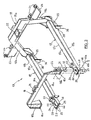
Figure 2 is a perspective view showing a rear part of the main frame of the straddle carrier, detached and separated from an auxiliary frame for the grape-harvesting equipment which stands on the ground, supported by four struts; -
Figure 3 is an exploded perspective view showing the auxiliary frame for the grape-harvesting equipment shown inFigure 2 , on a larger scale; -
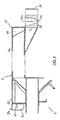
Figure 4 is a longitudinal section view of a girder forming part of the main frame of the self-propelled multi-purpose straddle carrier; -
Figure 5 is a view of a girder of the auxiliary frame, partly in lateral elevation and partly in longitudinal vertical section; -
Figure 6 is a cross-sectional view of the girder ofFigure 5 , taken along the line VI-VI; -
Figure 7 is a vertical longitudinal section showing the girders inFigures 4 and5 coupled together; -
Figure 8 is a cross-sectional view, along the line VIII-VIII inFigure 7 ; -
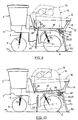
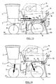
Figures 9-11 are schematic diagrams similar to that inFigure 1 , showing successive steps in the process of removal and deposition of the auxiliary frame carrying the grape-harvesting equipment; -
Figures 12-14 are schematic diagrams similar to those inFigures 1 and9-11 , showing successive steps in the approach, alignment, docking and coupling of the main frame of the self-propelled straddle carrier and the auxiliary frame carrying the grape-harvesting equipment; and -
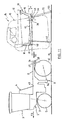
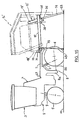
Figure 15 is a schematic diagram similar toFigure 12 , showing the self-propelled multi-purpose straddle carrier and an auxiliary frame bearing a sprayer equipment, at the beginning of the alignment phase. - Referring first to
Figure 1 , there is shown a self-propelled multi-purpose straddle carrier comprising amain frame 1, consisting essentially of two parallel and substantially horizontal girders 2 (not visible inFigure 1 , but at least one of them is clearly visible inFigures 2 ,4 ,7 ,10 ,11 ,12 ,13, 14 and15 ). Thegirders 2 are bridged at their front section by at least one crosspiece, which together with thegirders 2 forms a rigid carrying frame for supporting a driver'scab 3 and anpower unit 4 such as a diesel engine, suitable for driving the hydraulic pumps and the electrical generator, producing the hydraulic and electrical energy necessary for operating the various electrical and hydraulic units on the self-propelled straddle carrier and the equipment mounted thereto. - The
main frame 1 is mounted on four ground-engaging wheels, i.e., twofront driving wheels 5 and two rear wheels 6 (only one front wheel and one rear wheel are visible inFigure 1 ). - Each
front wheel 5 is supported by amechanism 7, which constitutes both a lifting device and a steering device and has, for example, a structure such as that described inFR-A-2 551 014 - Each
rear wheel 6 is supported by an articulatedarm 8, comprising a stationaryvertical part 8a fixed rigidly to one of the twogirders 2 of themain frame 1 and extending downwards from the girder, and apivotable part 8b connected via a horizontal pivot axis to the lower end ofpart 8a and extending almost horizontally therefrom to the rear of the carrier. Thewheel 6 is mounted in the rear end of thesection 8b of thearm 8. - A
hydraulic cylinder 9 is mounted substantially vertically between thepart 8b of eacharm 8 and themain frame 1, for pivotingpart 8b of thearm 8 and of the corresponding wheel in a vertical plane when the cylinder is actuated. Accordingly, when activated selectively, the twohydraulic cylinders 9 and the two hydraulic cylinders provided within the lifting andsteering devices 7 of the twofront wheels 5, allow themain frame 1 to be raised and lowered with respect to theground 10. - It is well known that the above-mentioned cylinders can also be used as inclination compensation means, when the self-propelled straddle carrier moves along a slope. It is also well known that at least two of the four
wheels wheels hydraulic motors 11 and 12 are incorporated into the hubs of these wheels. - The
main frame 1 carries a detachableauxiliary frame 13, connected to the main frame by detachable connection means described in greater detail below. Theauxiliary frame 13 itself supports anequipment 14, mainly comprising in the example shown inFigure 1 aharvesting unit 15 and at least one bin orhopper 16, and preferably two tipper bins located on either side of theharvesting unit 15 for temporary storage of the grape bunches or grape berries harvested. InFigure 1 , theequipment 14 is shown only in phantom outlines, as it is well-known equipment and its detailed description is therefore not necessary for a good understanding of the present invention. - Referring now to
Figures 2 and3 , one can see that theauxiliary frame 13 comprises essentially two parallel, substantially horizontal beams orgirders 17, bridged at their front ends by afront crossbar 18 and at their rear ends by arear crossbar 19. The spacing of the two girders of theauxiliary frame 13 corresponds to the spacing of the twogirders 2 of themain frame 1. - Each
girder 17 of theauxiliary frame 13 has, at least along a substantial part of its length, a profiled structure in the form of an inverted U, dimensioned for receiving one of the twogirders 2 of themain frame 1 by sliding, in a manner described in further detail below. Eachgirder 2 consists, for example, of a caisson girder having rectangular or square section. - Each of the two
crossbars auxiliary frame 13 includes an upperhorizontal crosspiece 18a or 19a and twolegs crosspieces 18a and 19a, asupport mount 21 or 22 (respectively) is fixed for a front or rear support assembly (not shown), which allows the known mounting of aharvesting unit 15 in a hanging position. - Each of the two
legs 19b of therear crossbar 19 is provided with asupport 23, which in turn supports twojournals 24 used as a pivot for one of the twotipper bins 16. The twolegs 19b of therear crossbar 19 are for example welded to the rear extremities of the twogirders 17 of theauxiliary frame 13, such that the twogirders 17 and therear crossbar 19 form a unitary weld assembly. - The
front crossbar 18 constitutes another weld assembly, comprising at the lower end of each of itslegs 18b abase plate 18c which can be bolted, for example by fourbolts 25, to asupport plate 26, which is welded to theupper surface 17a of the correspondinggirder 17 in the front section thereof, as shown inFigure 3 . - Each of the two
girders 2 of themain frame 1 extends rearwardly beyond the articulatedarms 8, and its free rear end can be inserted into the front end of the channel formed by the inverted U profiled structure of the correspondinggirder 17 of theauxiliary frame 13. It then slides longitudinally into the interior of said channel, being guided by the lateral walls of the channel. In order to facilitate introduction of the free rear end of eachgirder 2 into the channel of the inverted U profiled structure of the correspondinggirder 17, the caisson girder in eachgirder 2 is ending at its free rear extremity in a corner-shapedstructure 27 with lateral faces 28 converging backwards and upwards. For the same purpose, each of the two inverted U profiled structures constituting thegirders 17 of theauxiliary frame 13 has at its front section two lateral wings, which diverge both forwardly and downwardly, thus forming an entry convergence for the corner-shapedstructure 27 at the rear end of thecorresponding girder 2 of themain frame 1. - In order to facilitate the movement of the
girders 2 into the channels defined by the respective inverted U profiled structures in thegirders 17 of theauxiliary frame 13, the auxiliary frame comprises, adjacent the front end of eachgirder 17, an anti-friction device suitable for contacting theupper surface 2a of the caisson girder constituting thecorresponding girder 2 of themain frame 1. - In particular, as shown in
Figures 3 ,5 ,7 and 8 , each anti-friction device may consist of aroller 31 mounted for rotation about anaxle 32 and having ends supported by the vertical walls of a casing or supporthousing 33. Eachhousing 33 is fixed, for example by welding, to the base-plate 18c of the twocorresponding legs 18b of thefront crossbar 18. Eachroller 31 partly protrudes into the interior of the inverted U profiled structure of the correspondinggirder 17 via slot-shaped openings, which are generally designated byreference 34 inFigures 3 and5 and which are provided and vertically aligned in the base-plate 18c, thesupport plate 26 and theupper surface 17a of the corresponding profiledgirder 17. - In the area adjacent its rear end, the inverted U profiled structure making up each
girder 17 is strengthened by acaisson reinforcement structure 35 clearly shown inFigures 5 and7 . Eachreinforcement structure 35 has astop 36 attached thereto for cooperation with anotherstop 37 provided in the rear area of each of the two caisson profiles making up thegirders 2 of themain frame 1, in order to define a stop position limiting the longitudinal displacement of themain frame 1 with respect to theauxiliary frame 3, when thegirders 2 are introduced and slid longitudinally in the channel of the inverted U profiled structure within the twogirders 17 of theauxiliary frame 13. The stops 36 and 37 also have a centring function, as shown below. - Each of the two
girders 2 in themain frame 1, and each of the twogirders 17 in theauxiliary frame 13, comprise the following structure adjacent their rear ends: one girder a male,truncated cone part 38, the other a femaletruncated cone part 39 with a truncated cone receptacle 39a of a shape complementary to themale part 38, allowing that part to fit tightly into thefemale part 39. - In the example shown, each of the two
female parts 39 is attached to the rear end of the caisson girder of thecorresponding girder 2 of themain frame 1, so that it is offset backwards and downwards with respect to the corner-shapedstructure 27, the geometric axis of the truncated cone receptacle 39a of thefemale part 39 being orientated substantially vertically. Each maletruncated cone part 38 is fixed rigidly to the reinforcingstructure 35 of the inverted U profiled structure of the correspondinggirder 17, in immediate proximity to the wall of thefront end 41 of the reinforcingstructure 35, so that the maletruncated cone part 38 extends substantially vertically downwards from the reinforcingstructure 35 and below it, and the upper end of the foremost generator line of said maletruncated cone part 38 is aligned substantially vertically to the wall of thefront end 41, as shown inFigure 5 . - Preferably, the two stops 37 may consist of vertical sheet metal plates bent into a V and fixed respectively, for example by welding, behind the
female parts 39, as can be seen inFigures 2 and4 . Under these circumstances, the two stops 36 may also consist of two vertical sheet metal plates bent into a V and fixed respectively, for example by welding, to thereinforcement structures 35 on the inverted U profiled structures of each of the twogirders 17, so that they extend downwards behind the maletruncated cone parts 38, at such a distance therefrom that, when themain frame 1 is in the above-mentioned stop position defined by thestops truncated cone part 38 can fit firmly into the correspondingfemale part 39 through upward vertical displacement of themain frame 1 in relation to theauxiliary frame 13. - Preferably, the
upper surface 2a of the caisson girder constituting thegirder 2 in themain frame 1 should, in the area of its front end, have an opening orcavity 42 as can be seen inFigure 4 . Each opening orcavity 42 is foreseen for receiving a lower part of one of the tworollers 31 when themain frame 1 is in the stop position defined by thestop members Figures 7 and 8 . Under these circumstances, theupper surface 17a of each inverted U profiledstructure girder 17 on theauxiliary frame 13 rests on asupport piece 2b fixed to the front end of thecorresponding girder 2 so that a narrow gap is left between thewalls girders - When the
main frame 1 andauxiliary frame 13 are in the assembled position, as shown inFigure 7 , they may be affixed to each other in a detachable manner, using connection means comprising two screws or bolts 43, which pass respectively intosmooth holes 44 located at the lower end of thefemale parts 39 and which are screwed into the respective threadedholes 45 in the male truncated cone parts as shown inFigure 7 . - The detachable connection means may further comprise two locking pins 46. Each locking
pin 46 may be inserted through holes withhorizontal axes 47 in thelateral wings 2c of thesupport piece 2b attached to eachgirder 2 of themain frame 1, and into holes withhorizontal axes 48 in eachgirder 17 of themain frame 13, adjacent the front end of each of thegirders 17. Theholes main frame 1 is in the end position defined by thestops rollers 31 is received in theopening 42 in each of the twomain frame girders 2. Preferably, theholes 48 should have an oblong shape as shown inFigure 5 . - A holding device should preferably be provided for preventing the locking pins 46 from slipping out of the
holes holes 47 in eachgirder 2 takes the form of a key-hole (Figure 4 ) and eachpin 46 comprises astop collar 46a suitable for contacting the exterior of one of the lateral wings in the inverted U profiled structure of the correspondinggirder 17, and arod 46b which, once thepin 46 is fully engaged in theholes structure 17, thereby preventing thepin 46 from coming out, as shown inFigures 7 and 8 . - Four elongate supports, that is two
front struts 49 and tworear struts 51, are provided for supporting theauxiliary frame 13 and theharvesting equipment 14 when theauxiliary frame 13 is separated from themain frame 1 of the self-propelled straddle carrier, as can be seen particularly inFigures 2 and11 . Each of the front struts 49, by way of example, may have the shape of an inverted L and consists of tubular profiles with rectangular sections and fixed to each other, for example by welding. Twosleeves 52, also with rectangular sections, are fixed respectively to thegirders 17 of theauxiliary frame 13, close to the base of thefront crossbar 18. Eachsleeve 52 is dimensioned such that the free end of thehorizontal branch 49a of one or another of the front struts 49 can be slidingly received therein. - Each of the two
rear struts 51 consists essentially of a tubular profile, provided at its lower end with a base-plate 53. Its upper end can be slid into asocket 54 fixed rigidly, for example by welding, to thereinforcement structure 35 of one or other of the twogirders 17 of theauxiliary frame 13. - As can be seen in particular in
Figures 5 and 6 , eachsocket 54 is attached under the correspondingreinforcement structure 35 such that its upper end is closed by thereinforcement structure 35 and its lower end is open for receiving the upper extremity of the correspondingrear strut 51. The geometric axis of eachsocket 54 is inclined slightly backwards in relation to the vertical. - Each
socket 54 comprises two alignedholes 55, with horizontal axes, aligned with two holes (not shown) in the upper end of eachrear strut 51 when this strut is slid to the end of the correspondingsocket 54. Theholes 55 in thesockets 54, and the corresponding holes in the rear struts 51, are dimensioned so as to receive the locking pins 46. In this way, when thepins 46 are removed from theholes girders sockets 54 on thegirders 17. - As illustrated in
Figure 11 , the rear struts 51 are longer than the front struts 49, such that the twogirders 17 on theauxiliary frame 13 are inclined at an angle to the horizontal when theauxiliary frame 13 is supported by thestruts auxiliary frame 13 is supported by thestruts rollers 31 are just in contact with theupper surface 2a of thegirders 2 in the main frame, the upper end of thefemale parts 39 is taking a position slightly below the lower end of the maletruncated cone parts 38. This means that thefemale parts 39 can pass below themale parts 38 when themain frame 1 is driven backwards below themain frame 13 between thestruts Figure 13 . For example, the angle α may be about 4-5°. - In order to ensure guidance of the two
girders 2 in themain frame 1 inside the channels of the inverted U profiledstructure girders 17 until thestops girders 17 when theauxiliary frame 13 is supported by thestruts lateral wings 17b and 17c on the two inverted U profiled structures has a vertical dimension that increases from the front to the back of theauxiliary frame 13, as is illustrated inFigure 12 . It is not essential for the twowings 17b and 17c to have a vertical dimension that increases from the front to the back of theauxiliary frame 13, or for their vertical dimensions to increase in the same proportion. For example, in the rear region of theauxiliary frame 13, the outerlateral wing 17b may have a greater vertical dimension than the inner lateral wing 17c, as shown inFigure 6 . - In the same manner, in order to guarantee that the
stops main frame 1 is driven backwards under theauxiliary frame 13, even though thegirders 17 are inclined at an angle α to the horizontal when theauxiliary frame 13 is supported by thestruts stops 36 have a considerably greater vertical dimension, for example, at least twice the vertical dimension of the maletruncated cone parts 38, as is illustrated byFigure 5 . It is also clear that the V-shape of the plates constituting thestops girders stops - In addition, in the rear part of the
auxiliary frame 13, at least one of the twolateral wings 17b and 17c in each of the inverted U profiled structures making up thegirders 17, e.g., the twolateral wings 17b and 17c shown inFigure 6 , havelower parts 56 that diverge laterally and downwardly away from each other. Eachlower part 56 forms an angle to the vertical. The angle example, 5-7°. This also facilitates realignment of the rear parts of thegirders main frame 1 of the self-propelled straddle carrier is raised to load theauxiliary frame 13 and theequipment 14 that it carries. - There now follows a description of the operations required to disconnect and remove the
auxiliary frame 13 and theharvesting equipment 14 from themain frame 1 of the self-propelled straddle carrier, with reference toFigures 1 and9-11 . Starting from the position shown inFigure 1 , the two bins orhoppers 16 are first of all partly raised using the associated hydraulic cylinders. Themain frame 1 of the self-propelled straddle carrier is then raised by extending the piston rods of the hydraulic cylinders contained in the lifting andsteering devices 7 and the piston rods of thehydraulic cylinders 9, as indicated by arrows F1 inFigure 9 . - Next, the two locking
pins 46 are removed from theholes girders 17, and the front struts 49 are positioned in thesleeves 52. The rear struts 51 are then slid into thesockets 54 and locked into position using the two lockingpins 46, which are inserted into theholes 55 as shown inFigure 9 . - Next, the hydraulic hoses that connect the self-propelled straddle carrier to the
harvesting equipment 14, are removed, with the exception of the hoses to the hydraulic cylinders associated with the twobins 16. Next, the two bolts 43 (Figure 7 ) that keep the two maletruncated cone parts 38 coupled to the twofemale parts 39 are unscrewed and removed. After that, the twobins 16 are lowered using the associated hydraulic cylinders until thebins 16 come to rest on thebuffers 57 provided on the horizontal branches of the front struts 49, as can be seen also inFigure 9 . Next, the hoses from the hydraulic cylinders associated with thebins 16 are disconnected, as are the electrical wire harnesses. - Next, the
main frame 1 of the self-propelled straddle carrier is lowered by slowly and completely retracting the piston rods of thehydraulic cylinders 9 and the hydraulic cylinders incorporated in the lifting andsteering mechanisms 7, as indicated by the arrows F2 inFigure 10 . During this operation, thebase plates 53 of the rear struts 51 are first to rest on theground 10, whereupon the male andfemale parts rollers 31 remain positioned in theopenings 42 in thegirders 2 before the base plates of the front struts 49 contact theground 10. When the feet of the front struts have contacted the ground, therollers 31 leave of theopenings 42 and theauxiliary frame 13 bearing theharvesting equipment 14 is then completely disconnected from themain frame 1 of the self-propelled straddle carrier, which can now be moved forward slowly in a straight line as indicated by arrow F3 inFigure 11 . Theauxiliary frame 13 andharvesting equipment 14 will thus be left resting on theground 10 supported by thestruts - Tests carried out by the applicant have shown that the total time required to separate the
auxiliary equipment 13 andharvesting equipment 14 from themain frame 1 is approximately 15 minutes, including 8-10 minutes for uncoupling theauxiliary frame 13 from themain frame 1 of the self-propelled straddle carrier. - There now follows a description of the operations required to install the
auxiliary frame 13 andharvesting equipment 14 on the self-propelled straddle carrier, with reference toFigures 11-14 . Starting from the position shown inFigure 11 , in which themain frame 1 of the self-propelled straddle carrier is lowered as far as possible, the straddle carrier is driven backwards towards the front end of theauxiliary frame 13, which rests on theground 10 supported by thestruts harvest equipment 14, as shown by the arrow F4 inFigures 11 and12 . During this operation, the driver of the straddle carrier has a good view of the rear extremities of thegirders 2 of themain frame 1 and of the front extremities of thegirders 17 of themain frame 13. The driver can therefore easily bring the rear ends of thegirders 2 to a point just below the front ends of thegirders 17 on therear frame 13, in a position substantially, if not exactly, centred between thelateral wings 17b and 17c of the two inverted U profiled structures making up thegirders 17. - Next, the piston rods of the
hydraulic cylinders 9 and the hydraulic cylinders incorporated in the lifting andsteering devices 7 are extended slowly, as indicated by the arrows F5 inFigure 12 . Themain frame 1 is thus raised slowly until the upper surface of each of the two corner-shapedstructures 27, located at the rear end of the twogirders 2, just makes contact with theroller 31 at the front end of each of the twogirders 17 on theauxiliary frame 13, so that each of thestruts 49 is relieved of at least part of the weight of theauxiliary frame 13 andharvesting equipment 14. However the feet of thestruts 49 are not lifted, even to the slightest extent, from theground 10. During this operation, the two corner-shaped structures at the rear end of thegirders 2 may co-operate with thewings 29 at the front end of thegirders 17 in order to ensure centring of the rear extremities of thegirders 2 in relation to the front ends of thegirders 17 where necessary. - Next, the straddle carrier is moved further back below the
auxiliary frame 13, as indicated by the arrow F6 inFigure 13 , until the V-shaped stops on thegirders 2 of themain frame 1 come to rest against the V-shapedstops 36 on thegirders 17 of theauxiliary frame 13 and ensure a possible centring for the rear extremities of thegirders 2 with respect to the rear extremities of thegirders 17. During this operation, therollers 31 ride along the upper surface of thegirders 2 until their lower part engages or is at least positioned in theopenings 42 of thegirders 2 at the moment when thestops truncated cone parts 38 are aligned with the respective femaletruncated cone parts 39. - Next, the
hydraulic cylinders 9 and the hydraulic cylinders incorporated in the lifting andsteering devices 7 are extended completely as indicated by the arrows F7 inFigure 14 , in order to raise themain frame 1. During this operation, thesupport pieces 2b in thegirders 2 are brought into contact with the lower face of theupper wall 17a of thegirders 17 if they were not in contact already, and then thegirders 17 pivot about the virtual axis defined by the contact points between thesupport pieces 2b and the girders 17 (the angle α decreases). At the same time, thestops 37 slide vertically along thestops 36 and thefemale parts 39 couple together with themale parts 38. Simultaneously, therollers 31 move into theopenings 42 if they were not already in there, and theholes 47 on thegirders 2 become aligned with theholes 48 at the front end of thegirders 17. When the piston rods of the cylinders are completely extended, the feet of thestruts ground 10 as shown inFigure 14 . At that moment, the bolts 43 can be inserted through thesmooth holes 44 in thefemale parts 39, screwed into the threadedholes 45 in the maletruncated cone parts 38 and firmly tightened in order to prevent uncoupling of the male andfemale parts harvesting equipment 14. - The two locking pins 46 may then be removed in order to allow removal of the two
rear struts 51. Next, the two lockingpins 46 are inserted into the alignedholes front extremities 17 of theauxiliary frame 13 to thegirders 2 of themain frame 1. - The electrical wire harnesses and all the hoses for actuation of the hydraulic cylinders, including those for the hydraulic cylinders associated with the two
bins 16, are then connected to the self-propelled straddle carrier. Next, the hydraulic cylinders associated with thebins 16 are actuated in order to slightly lift the bins and thus allow removal of the front struts 49. Thebins 16 are then lowered back into their normal transport position. - Finally, the piston rods of the
hydraulic cylinders 9 and the hydraulic cylinders included in the lifting andsteering devices 7 are retracted at least partially in order to bring the self-propelled straddle carrier back to its road configuration. The straddle carrier is then ready for use as a grape-harvesting machine. - The tests carried out by the applicant have shown that the total time required for performing the installation and coupling of the
auxiliary frame 13 andharvesting equipment 14 to themain frame 1 of the self-propelled straddle carrier is not more than 20 minutes, including 10-12 minutes for the approach and coupling of theauxiliary frame 13 to themain frame 1. This is a much shorter time than that required for the straddle carriers described inFR-A-2 536 949 FR-A-2 554 668 -
Figure 15 offers a view similar toFigure 12 , showing (in phantom lines) an spraying equipment 14' being installed on themain frame 1 of the self-propelled straddle carrier described above. Here, the equipment 14' is borne by an auxiliary frame 13' supported on theground 10 bystruts auxiliary frame 13 of theharvesting equipment 14.Elements auxiliary frame 13 and will not be described in detail again. In fact, the auxiliary frame 13' is almost identical to theauxiliary frame 13, with the exception of the front crossbar 18', the rear crossbar 19' and other support structures that are more specifically adapted for receiving and supporting the spraying equipment 14' or other elements associated therewith. The spraying equipment is of a common type and a detailed description will not be given as it is not necessary for understanding of the invention. - Given the great similarity between the
auxiliary frames 13 and 13', it will be readily understood that installation of the equipment 14' on themain frame 1 of the self-propelled straddle carrier, and its removal from themain frame 1, can be performed in a manner very similar to the procedure described above for the installation and removal of theequipment 14. - Of course, other items of equipment such as tillage equipment, devices for pruning vines or other fruit-bearing shrubs planted in rows, work platforms or other material can be provided for selective installation on the
main frame 1 of the self-propelled straddle carrier in stead of theequipment 14 or 14'. Each time, the equipment is fitted with an auxiliary frame similar to theauxiliary frames 13 and 13' described above. - In addition, it is understood that the above description of an embodiment of the invention has been given only by way of example and that it is not limiting in any way, and that alternatives may be developed by people skilled in the art without departing from the scope of the invention as defined by the claims.
- For example, the respective positions of the male and
female coupling elements girders 2 of themain frame 1, while thefemale parts 39 may be affixed to thegirders 17 of theauxiliary frame 13. - The
harvesting equipment 14 may include a belt conveyor for transporting the harvested crop continuously into a trailer drawn by a tractor moving along a neighbouring row. In this case, instead of being installed on the main frame of the self-propelled straddle carrier, as is the case with the prior harvesting machines, it is preferable to install the belt conveyor directly on theauxiliary frame 13, replacing at least one of the twobins 16. This will allow a considerable time saving when the evacuation belt has to be removed at the same time as the harvesting equipment. - Further, the angle () of the frame may also be realised by other means than the difference in length between the front and rear struts. For example, it is possible to choose struts of equal length, but to attach them to the auxiliary frame at different heights. The attachment points for the front struts may be located higher than the attachment points for the rear struts.
Claims (18)
- Means for mounting equipment (14) intended for installation on a multi-purpose self-propelled straddle carrier for the cultivation, treatment and harvesting of fruit-bearing shrubs planted in rows, said mounting means (1, 13, 39, 41) comprising:on the straddle carrier, a main frame (1) mounted on ground-engaging wheels (5, 6) with lifting devices (7, 9) between the wheels and the main frame for selective lifting and lowering of the main frame with respect to the ground (10);on the equipment (14) an auxiliary frame (13) suitable for connection to the main frame (1) using detachable connection means (43, 46);a number of elongate supports (49, 51) for supporting the auxiliary frame (13) on the ground (10) when the auxiliary frame is separated from the main frame (1),the main frame (1) and the auxiliary frame (13) both including two parallel and substantially horizontal girders (2 or 17); and further comprisingon one of the main or auxiliary frames (1, 13), longitudinal guidance means, operable to co-operate with the two girders (2) on the other frame for guiding the two frames with respect to each other when the main frame (1) moves longitudinally in relation to the auxiliary frame (13) while being supported by the elongate supports (49, 51); anda stop member (36, 37) on at least one of the frames (1 and 13), able to co-operate with the other frame for limiting the longitudinal path of travel of the main frame (1) along the auxiliary frame (13) and to define a stop position that allows the two frames (1 and 13) to be assembled and affixed using said connection means (43, 46),characterised in that the two girders (2) on one of the two frames (1 and 13) have a predetermined spacing and comprise each a caisson girder, and the two girders (17) on the other frame have the same predetermined spacing and a structure forming a channel suitable for receiving one of the two caisson girders (2), said channel constituting said longitudinal guidance means (17).
- Mounting means according to Claim 1, characterised in that said elongate supports comprise two front elongate supports (49) and two rear elongate supports (51) with lengths and/or points of connection to the auxiliary frame, so that the two girders (17) of the auxiliary frame (13) are inclined at an angle (α) of about 4-5° to the horizontal when the auxiliary frame (13) is supported by the elongate supports (49, 51).
- Mounting means according to Claim 2, characterised in that the two caisson girders (2) belong to the main frame (1) and have a rectangular cross-section, and the two girders (17) of the auxiliary frame (13) have, at least for a substantial part of their length, a profiled structure with a transverse section in the shape of an inverted U.
- Mounting means according to Claim 3, characterised in that the auxiliary frame (13) comprises, at the front end of each profiled structure (17), an anti-friction device (31) suitable for contacting the upper surface (2a) of the corresponding girder in the main frame (1) which is received into the profiled structure.
- Mounting means according to Claim 4, characterised in that the anti-friction device (31) is a roller mounted to rotate about an axis (32) located above an upper surface (17a) of the profiled structure and partly protruding into the interior of the profiled structure through an opening (34) made in the upper surface of the profiled structure.
- Mounting means according to Claim 3, characterised in that the upper surface (2a) of each caisson girder (2) in the main frame (1) comprises an opening or cavity (42) suitable for receiving a lower part of the roller (31) when the main frame is in the stop position defined by the stop members (36, 37).
- Mounting means according to any of the Claims 3 to 6, characterised in that each of the two girders (2) on the main frame (1) and each of the two girders (17) on the auxiliary frame (13) are provided in the area adjacent their rear ends, with a male truncated cone part (38) on the one girder and a female truncated cone part (39) on the other, the two male parts (38) and the two female parts (39) being suitable for mating into each other through vertical displacement of the main frame (1) relative to the auxiliary frame (13) while the main frame is in the stop position defined by the stop members (36, 37).
- Mounting means according to Claim 7, characterised in that the female parts (39) each have a smooth axial hole (44) at the bottom of their truncated cone-shaped cavity, the male parts (38) each have a threaded axial hole (45), and the detachable connection means (43, 46) comprise two bolts (43) that pass through the smooth holes (44) of the female parts (39) and are screwed into the threaded holes (45) in the male parts.
- Mounting means according to any of the Claims 3 to 8, characterised in that each of the caisson girders (2) in the main frame (1) ends at its rear end in a corner-shaped structure (27) with lateral faces (28) that converge both backwardly and upwardly.
- Mounting means according to Claim 9 when appended to Claim 8, characterised in that each of the two female parts (39) is affixed to the rear end of the corresponding caisson girder (2) such that they are offset backwards and downwards with respect to the corner-shaped structure (27), and the stop members (36, 37) include, on the one hand, a first pair of vertical plates (37) of sheet metal bent into a V and affixed to the respective female parts (39) behind them, and, on the other hand, a second pair of vertical plates (36) of sheet metal bent into a V, which plates are affixed to the respective profiled structures (17) on the auxiliary frame (13), extend downwards from the profiled structures behind the male truncated cone parts (38) and have vertical dimensions of approximately twice the vertical dimensions of the male truncated cone parts (38).
- Mounting means according to any of the Claims 3 to 10, characterised in that each of the two profiled structures (17) of the auxiliary frame (13) has lateral wings (29) that diverge both forwardly and downwardly.
- Mounting means according to any of the Claims 3 to 11, characterised in that each of the two profiled structures (17) on the auxiliary frame (13) has at least one lateral wing (17b) with a vertical dimension that increases from front to back along the auxiliary frame (13).
- Mounting means according to Claim 12, characterised in that in the rear part of the auxiliary frame (13), at least one (17b) of the two lateral wings (17b, 17c) of each profiled structure (17) has a lower part (56) that diverges laterally and downwardly while extending away from the other (17c) lateral wing.
- Mounting means according to any of the Claims 6 to 13, characterised in that the detachable connection means (43, 46) further comprise two locking pins (46), inserted into holes (47, 48) with horizontal axes, provided in each girder (17) of the auxiliary frame (13) and in each corresponding girder (2) of the main frame (1), said holes being aligned only when the lower part of the roller (31) has entered the opening or cavity (42).
- A method for the mounting of equipment selected from a variety of various items (14, 14', etc.) onto a multi-purpose self-propelled straddle carrier for the cultivation, treatment and harvesting of fruit-bearing shrubs planted in rows, said self-propelled straddle carrier comprising a main frame (1) suitable for lifting and lowering and comprising a first pair of parallel and spaced girders (2), the equipment being supported by elongate supports (49, 51) when in a state of waiting prior to installation on the self-propelled straddle carrier, and comprising an auxiliary frame (13) suitable for connection to the main frame (1) by detachable connection means (43, 46) and comprising a second pair of girders (17),
said method being characterised in that it comprises:a) using, for one of the first and second pairs of girders (2 and 17), two girders having a predetermined spacing and having each a structure that forms a channel suitable for receiving and guiding one of the girders of the other pair of girders during longitudinal displacement of the main frame (1) with respect to the auxiliary frame (13) supported by the elongate supports (49, 51), the girders of the other pair of girders having the same predetermined spacing and comprising each a caisson girder (2);b) moving the self-propelled straddle carrier to a position so that each of the girders (2) of the first pair is aligned in substantially the same vertical plane as a corresponding girder from the second pair (17), and the end of each of the girders (2) of the first pair is) at a level lower than the first end of the corresponding girder of the second pair of girders (17);c) raising the main frame (1) over a distance sufficient to make the respective ends of the first and second pairs of girders (2 and 17) engage, the one within the other;d) moving the main frame (1) longitudinally with respect to the auxiliary frame (13) to a position defined by the mutual engagement of stop members (36, 37);e) raising the main frame (1) further such that the first pair of girders (2) carries the second pair of girders (17), the auxiliary frame (13) and the equipment borne by that frame, and eliminating the load from the weight of the auxiliary frame (13) and the equipment unloading on the elongate supports (49, 51);f) affixing the auxiliary frame (13) to the main frame (1) using the detachable connection means (43, 46);g) removing the elongate supports (49, 51); andh) lowering the main frame (1) to bring the carrier to the required level for road transport or for operation of the installed equipment. - A method according to Claim 15, characterised in that:said method involves use of the elongate supports (49, 51) that have lengths and/or points of connection to the auxiliary frame (13) such that the two girders (17) on the auxiliary frame are inclined upwards from their first end to their other end at an angle of some 4-5° to the horizontal when the auxiliary frame is supported by said elongate supports, andstep (e) of the lifting procedure includes a substep during which the two girders (17) in the auxiliary frame (13) pivot around a virtual axis defined by the points of contact between the first ends of the two girders (17) of the auxiliary frame and the two girders (2) on the main frame.
- A method according to Claim 16, characterised in that the pivoting step comprises a positioning step during which the male (38) and female (39) conical parts affixed to the girders (2 and 17) couple together automatically to ensure precise positioning of the other ends of the girders (17) on the auxiliary frame (17) in relation to the girders (2) on the main frame.
- A method according to any of the Claims 15 to 17, characterised in that during step (d), an anti-friction device between the main frame (1) and the auxiliary frame (13) is used.
Applications Claiming Priority (3)
| Application Number | Priority Date | Filing Date | Title |
|---|---|---|---|
| FR0303090A FR2852193B1 (en) | 2003-03-13 | 2003-03-13 | SUPPORT ASSEMBLY FOR CULTIVATION EQUIPMENT, TREATMENT OR HARVESTING FOR MULTI-PURPOSE AUTOMOTIVE SLEEVE |
| FR0303090 | 2003-03-13 | ||
| PCT/EP2004/050301 WO2004080155A1 (en) | 2003-03-13 | 2004-03-12 | Means for mounting agricultural equipment to a multi-purpose self-propelled straddle carrier |
Publications (2)
| Publication Number | Publication Date |
|---|---|
| EP1608213A1 EP1608213A1 (en) | 2005-12-28 |
| EP1608213B1 true EP1608213B1 (en) | 2014-05-07 |
Family
ID=32893263
Family Applications (1)
| Application Number | Title | Priority Date | Filing Date |
|---|---|---|---|
| EP04720011.8A Expired - Lifetime EP1608213B1 (en) | 2003-03-13 | 2004-03-12 | Means for mounting agricultural equipment to a multi-purpose self-propelled straddle carrier |
Country Status (7)
| Country | Link |
|---|---|
| US (1) | US7549279B2 (en) |
| EP (1) | EP1608213B1 (en) |
| AU (1) | AU2004218943A1 (en) |
| ES (1) | ES2482698T3 (en) |
| FR (1) | FR2852193B1 (en) |
| NZ (1) | NZ541910A (en) |
| WO (1) | WO2004080155A1 (en) |
Families Citing this family (10)
| Publication number | Priority date | Publication date | Assignee | Title |
|---|---|---|---|---|
| US20090229436A1 (en) * | 2008-03-11 | 2009-09-17 | Crain Cutter Company, Inc. | Undercut saw height adjustment, handle, blade guard improvements |
| US8950367B2 (en) * | 2012-07-30 | 2015-02-10 | Caterpillar Inc. | Cooling fan shroud |
| CN109068577A (en) | 2016-02-18 | 2018-12-21 | 育种制造有限公司 | Device for manipulating tools |
| US10953918B2 (en) | 2016-05-19 | 2021-03-23 | Vermeer Manufacturing Company | Self-propelled vehicles including a differential system |
| CA3022138C (en) | 2016-05-19 | 2020-11-24 | Vermeer Manufacturing Company | Self-propelled baling vehicle |
| US11166403B2 (en) | 2016-05-19 | 2021-11-09 | Vermeer Manufacturing Company | Steered caster wheel systems |
| US10980183B2 (en) * | 2017-08-11 | 2021-04-20 | Vermeer Manufacturing Company | Self-propelled vehicles with extendable devices |
| US10743464B2 (en) | 2017-08-23 | 2020-08-18 | Cnh Industrial America Llc | System for aligning skid-mounted equipment on an agricultural product applicator |
| US10575466B2 (en) * | 2017-11-20 | 2020-03-03 | Deere & Company | Modular mounting system for a cotton harvester |
| CA3052153A1 (en) * | 2019-08-16 | 2021-02-16 | Seedmaster Manufacturing Ltd. | Unidirectional implement operating apparatus |
Family Cites Families (22)
| Publication number | Priority date | Publication date | Assignee | Title |
|---|---|---|---|---|
| US2401183A (en) * | 1943-12-23 | 1946-05-28 | Int Harvester Co | Tractor-mounted implement |
| US3324637A (en) * | 1964-06-26 | 1967-06-13 | Massey Ferguson Ltd | Combine having quick detachable header |
| US3425194A (en) * | 1965-10-20 | 1969-02-04 | Avco Corp | Self-propelled implement assemblies |
| US3403802A (en) * | 1966-02-14 | 1968-10-01 | Vernon J. Lundell | Farm tractor |
| CH484588A (en) * | 1968-02-12 | 1970-01-31 | Labourier & Cie S A R L | Self-propelled device carrying a device for removable use, for agricultural work for example |
| US3599402A (en) * | 1970-02-16 | 1971-08-17 | Deere & Co | Corn-head-mounting structure |
| US3841429A (en) * | 1970-10-13 | 1974-10-15 | Bofors Ab | Device for a straddle-carrier or a similar vehicle |
| US3645074A (en) * | 1970-10-26 | 1972-02-29 | Deere & Co | Agricultural implement |
| DE2121495A1 (en) * | 1971-04-30 | 1972-11-02 | Josef Bautz Gmbh, 7968 Saulgau | Multi-purpose self-propelled agricultural machine |
| GB1544188A (en) * | 1976-05-11 | 1979-04-11 | Clayson Nv | Combine harvesters |
| US4057265A (en) * | 1976-11-24 | 1977-11-08 | Grace Bud W | Towing apparatus |
| FR2379976A1 (en) * | 1977-02-11 | 1978-09-08 | Bobard Jeune Sa Ets | IMPROVEMENTS TO STUDDING TRACTORS |
| FR2536949A1 (en) * | 1982-12-06 | 1984-06-08 | Braud Sa | VERSATILE CROPPERS FOR THE CULTIVATION, PROCESSING AND HARVESTING OF FRUIT TREE PLANTS ON LINE, ESPECIALLY THE VINE |
| FR2554668B2 (en) | 1982-12-06 | 1986-01-24 | Braud Sa | VERSATILE CROPPERS FOR THE CULTIVATION, TREATMENT AND HARVESTING OF FRUIT TREE PLANTS ONLINE, ESPECIALLY THE VINE |
| FR2551014B1 (en) | 1983-08-29 | 1989-06-30 | Braud Sa | LIFTING AND STEERING DEVICE FOR A STEERING WHEEL OF A VEHICLE |
| DE3418721A1 (en) * | 1984-05-19 | 1985-11-21 | Agro-Industrie-Projekt GmbH, 7441 Schlaitdorf | Self-propelled implement carrier |
| US4683969A (en) * | 1985-09-27 | 1987-08-04 | Littau Eugene G | Dimensionally-adjustable straddle-type crop-working vehicle |
| DE3911524A1 (en) * | 1989-04-08 | 1990-10-11 | Claas Ohg | AGRICULTURAL VEHICLE |
| US5092422A (en) * | 1989-12-12 | 1992-03-03 | Clemson University | Multipurpose agricultural tractor |
| US6875103B2 (en) * | 2002-01-07 | 2005-04-05 | Cnh America Llc | Apparatus and method for installing and removing a harvesting combine rotor |
| US6634162B1 (en) * | 2002-06-17 | 2003-10-21 | Matt Andros | Simultaneous processing of multiple rows of plants, especially trellised rows |
| US7175520B2 (en) * | 2003-07-15 | 2007-02-13 | Cnh America Llc | Cab arrangement for harvesting combine |
-
2003
- 2003-03-13 FR FR0303090A patent/FR2852193B1/en not_active Expired - Fee Related
-
2004
- 2004-03-12 ES ES04720011.8T patent/ES2482698T3/en not_active Expired - Lifetime
- 2004-03-12 NZ NZ541910A patent/NZ541910A/en not_active IP Right Cessation
- 2004-03-12 AU AU2004218943A patent/AU2004218943A1/en not_active Abandoned
- 2004-03-12 WO PCT/EP2004/050301 patent/WO2004080155A1/en not_active Ceased
- 2004-03-12 EP EP04720011.8A patent/EP1608213B1/en not_active Expired - Lifetime
- 2004-03-12 US US10/549,224 patent/US7549279B2/en not_active Expired - Fee Related
Also Published As
| Publication number | Publication date |
|---|---|
| US7549279B2 (en) | 2009-06-23 |
| ES2482698T3 (en) | 2014-08-04 |
| FR2852193B1 (en) | 2006-02-17 |
| US20070157592A1 (en) | 2007-07-12 |
| NZ541910A (en) | 2009-02-28 |
| WO2004080155A1 (en) | 2004-09-23 |
| EP1608213A1 (en) | 2005-12-28 |
| FR2852193A1 (en) | 2004-09-17 |
| AU2004218943A1 (en) | 2004-09-23 |
Similar Documents
| Publication | Publication Date | Title |
|---|---|---|
| US4986064A (en) | Harvesting machine | |
| US10327375B1 (en) | Side folding toolbar for chemical applicator | |
| US6076613A (en) | Forwardly-folding agricultural implement | |
| US8534981B1 (en) | Truck bed bale loader auxiliary assembly | |
| US4664202A (en) | Folding implement frame for grain drills and the like | |
| CA2019317C (en) | Three point hitch for truck | |
| US7549279B2 (en) | Mechanism for mounting agricultural equipment to a multi-purpose self-propelled straddle carrier | |
| US20090020369A1 (en) | Multiple configuration Implement Carrier Kit | |
| PL112546B1 (en) | Apparatus for handling materials especially for loadingpurposes | |
| US4768334A (en) | Tractor mounted swather | |
| CA2169313A1 (en) | Implement convertible between a use position and a transport position | |
| EP3868190B1 (en) | Implement support apparatus | |
| DE2508351A1 (en) | DEVICE FOR CHANGING THE POSITION OF A LOAD-BEARING TILE OF A TRANSPORT DEVICE | |
| MXPA01000934A (en) | Agricultural implement frame having a transport configuration and a working configuration. | |
| CA2230676C (en) | Blueberry harvester | |
| US4993914A (en) | Fallen tree removal implement | |
| US4351253A (en) | Tree planter and trailer | |
| CA1285808C (en) | Horizontally foldable implement | |
| EP1068015B1 (en) | Material processing plant | |
| US5071304A (en) | Multi-bale transporting machine for round bales | |
| US20060163381A1 (en) | Vehicle with readily demountable sprayer | |
| EP0269149B1 (en) | Folding beam of a seed drill | |
| GB2058730A (en) | Storing Wheeled Frames of Cargo Container Trailers | |
| US4439094A (en) | Method for storing wheeled frames of detachable cargo container type trailers | |
| CN1085936C (en) | Tractor mounted harvester with quick attach structure |
Legal Events
| Date | Code | Title | Description |
|---|---|---|---|
| PUAI | Public reference made under article 153(3) epc to a published international application that has entered the european phase |
Free format text: ORIGINAL CODE: 0009012 |
|
| 17P | Request for examination filed |
Effective date: 20051011 |
|
| AK | Designated contracting states |
Kind code of ref document: A1 Designated state(s): AT BE BG CH CY CZ DE DK EE ES FI FR GB GR HU IE IT LI LU MC NL PL PT RO SE SI SK TR |
|
| AX | Request for extension of the european patent |
Extension state: AL LT LV MK |
|
| DAX | Request for extension of the european patent (deleted) | ||
| RIN1 | Information on inventor provided before grant (corrected) |
Inventor name: MERANT, JEAN-CAMILLE Inventor name: BOSSARD, GUY, M., A., H. Inventor name: BERTHET, JEAN- PAUL |
|
| RAP1 | Party data changed (applicant data changed or rights of an application transferred) |
Owner name: CNH FRANCE S.A. |
|
| 17Q | First examination report despatched |
Effective date: 20110506 |
|
| GRAP | Despatch of communication of intention to grant a patent |
Free format text: ORIGINAL CODE: EPIDOSNIGR1 |
|
| INTG | Intention to grant announced |
Effective date: 20131107 |
|
| GRAS | Grant fee paid |
Free format text: ORIGINAL CODE: EPIDOSNIGR3 |
|
| GRAA | (expected) grant |
Free format text: ORIGINAL CODE: 0009210 |
|
| AK | Designated contracting states |
Kind code of ref document: B1 Designated state(s): AT BE BG CH CY CZ DE DK EE ES FI FR GB GR HU IE IT LI LU MC NL PL PT RO SE SI SK TR |
|
| REG | Reference to a national code |
Ref country code: GB Ref legal event code: FG4D |
|
| REG | Reference to a national code |
Ref country code: AT Ref legal event code: REF Ref document number: 665836 Country of ref document: AT Kind code of ref document: T Effective date: 20140515 |
|
| RAP2 | Party data changed (patent owner data changed or rights of a patent transferred) |
Owner name: CNH INDUSTRIAL FRANCE |
|
| REG | Reference to a national code |
Ref country code: IE Ref legal event code: FG4D |
|
| REG | Reference to a national code |
Ref country code: DE Ref legal event code: R096 Ref document number: 602004045028 Country of ref document: DE Effective date: 20140612 |
|
| REG | Reference to a national code |
Ref country code: ES Ref legal event code: FG2A Ref document number: 2482698 Country of ref document: ES Kind code of ref document: T3 Effective date: 20140804 |
|
| REG | Reference to a national code |
Ref country code: AT Ref legal event code: MK05 Ref document number: 665836 Country of ref document: AT Kind code of ref document: T Effective date: 20140507 |
|
| REG | Reference to a national code |
Ref country code: NL Ref legal event code: VDEP Effective date: 20140507 |
|
| PG25 | Lapsed in a contracting state [announced via postgrant information from national office to epo] |
Ref country code: FI Free format text: LAPSE BECAUSE OF FAILURE TO SUBMIT A TRANSLATION OF THE DESCRIPTION OR TO PAY THE FEE WITHIN THE PRESCRIBED TIME-LIMIT Effective date: 20140507 Ref country code: GR Free format text: LAPSE BECAUSE OF FAILURE TO SUBMIT A TRANSLATION OF THE DESCRIPTION OR TO PAY THE FEE WITHIN THE PRESCRIBED TIME-LIMIT Effective date: 20140808 Ref country code: CY Free format text: LAPSE BECAUSE OF FAILURE TO SUBMIT A TRANSLATION OF THE DESCRIPTION OR TO PAY THE FEE WITHIN THE PRESCRIBED TIME-LIMIT Effective date: 20140507 |
|
| PG25 | Lapsed in a contracting state [announced via postgrant information from national office to epo] |
Ref country code: AT Free format text: LAPSE BECAUSE OF FAILURE TO SUBMIT A TRANSLATION OF THE DESCRIPTION OR TO PAY THE FEE WITHIN THE PRESCRIBED TIME-LIMIT Effective date: 20140507 Ref country code: PL Free format text: LAPSE BECAUSE OF FAILURE TO SUBMIT A TRANSLATION OF THE DESCRIPTION OR TO PAY THE FEE WITHIN THE PRESCRIBED TIME-LIMIT Effective date: 20140507 Ref country code: SE Free format text: LAPSE BECAUSE OF FAILURE TO SUBMIT A TRANSLATION OF THE DESCRIPTION OR TO PAY THE FEE WITHIN THE PRESCRIBED TIME-LIMIT Effective date: 20140507 |
|
| PG25 | Lapsed in a contracting state [announced via postgrant information from national office to epo] |
Ref country code: PT Free format text: LAPSE BECAUSE OF FAILURE TO SUBMIT A TRANSLATION OF THE DESCRIPTION OR TO PAY THE FEE WITHIN THE PRESCRIBED TIME-LIMIT Effective date: 20140908 |
|
| PG25 | Lapsed in a contracting state [announced via postgrant information from national office to epo] |
Ref country code: SK Free format text: LAPSE BECAUSE OF FAILURE TO SUBMIT A TRANSLATION OF THE DESCRIPTION OR TO PAY THE FEE WITHIN THE PRESCRIBED TIME-LIMIT Effective date: 20140507 Ref country code: RO Free format text: LAPSE BECAUSE OF FAILURE TO SUBMIT A TRANSLATION OF THE DESCRIPTION OR TO PAY THE FEE WITHIN THE PRESCRIBED TIME-LIMIT Effective date: 20140507 Ref country code: BE Free format text: LAPSE BECAUSE OF FAILURE TO SUBMIT A TRANSLATION OF THE DESCRIPTION OR TO PAY THE FEE WITHIN THE PRESCRIBED TIME-LIMIT Effective date: 20140507 Ref country code: CZ Free format text: LAPSE BECAUSE OF FAILURE TO SUBMIT A TRANSLATION OF THE DESCRIPTION OR TO PAY THE FEE WITHIN THE PRESCRIBED TIME-LIMIT Effective date: 20140507 Ref country code: EE Free format text: LAPSE BECAUSE OF FAILURE TO SUBMIT A TRANSLATION OF THE DESCRIPTION OR TO PAY THE FEE WITHIN THE PRESCRIBED TIME-LIMIT Effective date: 20140507 Ref country code: DK Free format text: LAPSE BECAUSE OF FAILURE TO SUBMIT A TRANSLATION OF THE DESCRIPTION OR TO PAY THE FEE WITHIN THE PRESCRIBED TIME-LIMIT Effective date: 20140507 |
|
| REG | Reference to a national code |
Ref country code: DE Ref legal event code: R097 Ref document number: 602004045028 Country of ref document: DE |
|
| PG25 | Lapsed in a contracting state [announced via postgrant information from national office to epo] |
Ref country code: NL Free format text: LAPSE BECAUSE OF FAILURE TO SUBMIT A TRANSLATION OF THE DESCRIPTION OR TO PAY THE FEE WITHIN THE PRESCRIBED TIME-LIMIT Effective date: 20140507 |
|
| PLBE | No opposition filed within time limit |
Free format text: ORIGINAL CODE: 0009261 |
|
| STAA | Information on the status of an ep patent application or granted ep patent |
Free format text: STATUS: NO OPPOSITION FILED WITHIN TIME LIMIT |
|
| REG | Reference to a national code |
Ref country code: FR Ref legal event code: CD Owner name: CNH INDUSTRIAL FRANCE, FR Effective date: 20150302 |
|
| 26N | No opposition filed |
Effective date: 20150210 |
|
| REG | Reference to a national code |
Ref country code: DE Ref legal event code: R097 Ref document number: 602004045028 Country of ref document: DE Effective date: 20150210 |
|
| PGFP | Annual fee paid to national office [announced via postgrant information from national office to epo] |
Ref country code: GB Payment date: 20150119 Year of fee payment: 12 |
|
| PG25 | Lapsed in a contracting state [announced via postgrant information from national office to epo] |
Ref country code: SI Free format text: LAPSE BECAUSE OF FAILURE TO SUBMIT A TRANSLATION OF THE DESCRIPTION OR TO PAY THE FEE WITHIN THE PRESCRIBED TIME-LIMIT Effective date: 20140507 |
|
| PG25 | Lapsed in a contracting state [announced via postgrant information from national office to epo] |
Ref country code: LU Free format text: LAPSE BECAUSE OF FAILURE TO SUBMIT A TRANSLATION OF THE DESCRIPTION OR TO PAY THE FEE WITHIN THE PRESCRIBED TIME-LIMIT Effective date: 20150312 Ref country code: MC Free format text: LAPSE BECAUSE OF FAILURE TO SUBMIT A TRANSLATION OF THE DESCRIPTION OR TO PAY THE FEE WITHIN THE PRESCRIBED TIME-LIMIT Effective date: 20140507 |
|
| REG | Reference to a national code |
Ref country code: CH Ref legal event code: PL |
|
| REG | Reference to a national code |
Ref country code: FR Ref legal event code: PLFP Year of fee payment: 13 |
|
| REG | Reference to a national code |
Ref country code: IE Ref legal event code: MM4A |
|
| PG25 | Lapsed in a contracting state [announced via postgrant information from national office to epo] |
Ref country code: LI Free format text: LAPSE BECAUSE OF NON-PAYMENT OF DUE FEES Effective date: 20150331 Ref country code: CH Free format text: LAPSE BECAUSE OF NON-PAYMENT OF DUE FEES Effective date: 20150331 Ref country code: IE Free format text: LAPSE BECAUSE OF NON-PAYMENT OF DUE FEES Effective date: 20150312 |
|
| REG | Reference to a national code |
Ref country code: ES Ref legal event code: FD2A Effective date: 20160830 |
|
| GBPC | Gb: european patent ceased through non-payment of renewal fee |
Effective date: 20160312 |
|
| PG25 | Lapsed in a contracting state [announced via postgrant information from national office to epo] |
Ref country code: ES Free format text: LAPSE BECAUSE OF NON-PAYMENT OF DUE FEES Effective date: 20150313 |
|
| REG | Reference to a national code |
Ref country code: FR Ref legal event code: PLFP Year of fee payment: 14 |
|
| PG25 | Lapsed in a contracting state [announced via postgrant information from national office to epo] |
Ref country code: GB Free format text: LAPSE BECAUSE OF NON-PAYMENT OF DUE FEES Effective date: 20160312 |
|
| PG25 | Lapsed in a contracting state [announced via postgrant information from national office to epo] |
Ref country code: HU Free format text: LAPSE BECAUSE OF FAILURE TO SUBMIT A TRANSLATION OF THE DESCRIPTION OR TO PAY THE FEE WITHIN THE PRESCRIBED TIME-LIMIT; INVALID AB INITIO Effective date: 20040312 Ref country code: BG Free format text: LAPSE BECAUSE OF FAILURE TO SUBMIT A TRANSLATION OF THE DESCRIPTION OR TO PAY THE FEE WITHIN THE PRESCRIBED TIME-LIMIT Effective date: 20140507 |
|
| PG25 | Lapsed in a contracting state [announced via postgrant information from national office to epo] |
Ref country code: TR Free format text: LAPSE BECAUSE OF FAILURE TO SUBMIT A TRANSLATION OF THE DESCRIPTION OR TO PAY THE FEE WITHIN THE PRESCRIBED TIME-LIMIT Effective date: 20140507 |
|
| REG | Reference to a national code |
Ref country code: FR Ref legal event code: PLFP Year of fee payment: 15 |
|
| PGFP | Annual fee paid to national office [announced via postgrant information from national office to epo] |
Ref country code: NL Payment date: 20181221 Year of fee payment: 8 |
|
| PGFP | Annual fee paid to national office [announced via postgrant information from national office to epo] |
Ref country code: IT Payment date: 20200310 Year of fee payment: 17 |
|
| REG | Reference to a national code |
Ref country code: DE Ref legal event code: R119 Ref document number: 602004045028 Country of ref document: DE |
|
| PG25 | Lapsed in a contracting state [announced via postgrant information from national office to epo] |
Ref country code: DE Free format text: LAPSE BECAUSE OF NON-PAYMENT OF DUE FEES Effective date: 20201001 |
|
| PG25 | Lapsed in a contracting state [announced via postgrant information from national office to epo] |
Ref country code: IT Free format text: LAPSE BECAUSE OF NON-PAYMENT OF DUE FEES Effective date: 20210312 |
|
| PGFP | Annual fee paid to national office [announced via postgrant information from national office to epo] |
Ref country code: FR Payment date: 20230322 Year of fee payment: 20 |