EP1608169A1 - Multi function apparatus having scart connector and control method thereof - Google Patents
Multi function apparatus having scart connector and control method thereof Download PDFInfo
- Publication number
- EP1608169A1 EP1608169A1 EP05252952A EP05252952A EP1608169A1 EP 1608169 A1 EP1608169 A1 EP 1608169A1 EP 05252952 A EP05252952 A EP 05252952A EP 05252952 A EP05252952 A EP 05252952A EP 1608169 A1 EP1608169 A1 EP 1608169A1
- Authority
- EP
- European Patent Office
- Prior art keywords
- devices
- operation command
- connector
- multi function
- scart
- Prior art date
- Legal status (The legal status is an assumption and is not a legal conclusion. Google has not performed a legal analysis and makes no representation as to the accuracy of the status listed.)
- Withdrawn
Links
Images


Classifications
-
- G—PHYSICS
- G11—INFORMATION STORAGE
- G11B—INFORMATION STORAGE BASED ON RELATIVE MOVEMENT BETWEEN RECORD CARRIER AND TRANSDUCER
- G11B20/00—Signal processing not specific to the method of recording or reproducing; Circuits therefor
- G11B20/10—Digital recording or reproducing
-
- G—PHYSICS
- G11—INFORMATION STORAGE
- G11B—INFORMATION STORAGE BASED ON RELATIVE MOVEMENT BETWEEN RECORD CARRIER AND TRANSDUCER
- G11B19/00—Driving, starting, stopping record carriers not specifically of filamentary or web form, or of supports therefor; Control thereof; Control of operating function ; Driving both disc and head
- G11B19/02—Control of operating function, e.g. switching from recording to reproducing
-
- H—ELECTRICITY
- H04—ELECTRIC COMMUNICATION TECHNIQUE
- H04B—TRANSMISSION
- H04B1/00—Details of transmission systems, not covered by a single one of groups H04B3/00 - H04B13/00; Details of transmission systems not characterised by the medium used for transmission
- H04B1/06—Receivers
- H04B1/16—Circuits
- H04B1/20—Circuits for coupling gramophone pick-up, recorder output, or microphone to receiver
- H04B1/205—Circuits for coupling gramophone pick-up, recorder output, or microphone to receiver with control bus for exchanging commands between units
-
- H—ELECTRICITY
- H04—ELECTRIC COMMUNICATION TECHNIQUE
- H04N—PICTORIAL COMMUNICATION, e.g. TELEVISION
- H04N5/00—Details of television systems
- H04N5/76—Television signal recording
- H04N5/765—Interface circuits between an apparatus for recording and another apparatus
- H04N5/775—Interface circuits between an apparatus for recording and another apparatus between a recording apparatus and a television receiver
-
- H—ELECTRICITY
- H04—ELECTRIC COMMUNICATION TECHNIQUE
- H04N—PICTORIAL COMMUNICATION, e.g. TELEVISION
- H04N5/00—Details of television systems
- H04N5/76—Television signal recording
- H04N5/84—Television signal recording using optical recording
- H04N5/85—Television signal recording using optical recording on discs or drums
-
- H—ELECTRICITY
- H04—ELECTRIC COMMUNICATION TECHNIQUE
- H04N—PICTORIAL COMMUNICATION, e.g. TELEVISION
- H04N7/00—Television systems
- H04N7/10—Adaptations for transmission by electrical cable
Definitions
- the present invention relates to a multi function apparatus having a SCART (Syndicat des Constructeurs d'Appareils Radiorecepteurs et Televiseurs) connector and its control method, and more particularly, to a multi function apparatus having a SCART connector so that an AV-Link may be applied to the apparatus, and its control method.
- SCART Syndicat des Constructeurs d'Appareils Radiorecepteurs et Televiseurs
- An AV-Link is a function that allows an AV device to be connected to external equipments via cables so that various commands may be sent to the AV device from the external equipments without requiring direct manipulation of the AV device, thereby giving convenience to a user.
- An application of an AV device having an AV-link is a TV which may directly issue an order to an AV device such that the AV device records audio and video information output through the TV.
- an AV device is generally configured to have only one function, such as a DVD or VCD, so that the AV-Link may be easily applied as mentioned above.
- a recent trend is a multi function apparatus having many devices combined, each device having an independent function. If an AV-Link is applied to the multi function apparatus in the same way as the former case, the multi function apparatus may not determine which device should operate according to a command sent from the external equipment. Thus, there have been limitations in applying an AV-Link to the multi function apparatus.
- An aspect of the present invention provides a multi function apparatus having a SCART connector so that an AV-Link may be applied to the multifunction apparatus without problems. According to another aspect of the invention, there is provided a method of controlling the apparatus.
- a multi function apparatus in which a plurality of devices including first and second devices, each having an independent function, are combined, which includes a SCART (Syndicat des Constructeurs d'Appareils Radiorecepteurs et Televiseurs) connector to which a signal for connection to an external device is connected; and a selection unit for transmitting an operation command sent through the SCART connector to any of the first and second devices.
- SCART Syndicat des Constructeurs d'Appareils Radiorecepteurs et Televiseurs
- the operation command is transmitted through a tenth pin of the SCART connector.
- the multi function apparatus may further include a menu-processing unit (440) forming GUI (Graphic User Interface) so as to select any device that is to receive the operation command by the selection unit.
- GUI Graphic User Interface
- a method for controlling a multi function apparatus in which a plurality of devices including first and second devices, each having an independent function, are combined and in which a SCART connector to which a signal for connection to an external device is connected is provided, wherein the method includes receiving an operation command from the external device through the SCART connector; selecting one device between the first and second devices that is to be operated, and then transmitting the operation command to the selected device; and allowing the device receiving the operation command to conduct the operation.
- the selecting the device determines whether the first and second devices are in a prepared state, and then transmits the operation command to a device that is in a prepared state.
- the operation command may be transmitted through a tenth pin of the SCART connector.
- the selected device is one between the first and second devices, set in GUI for the operation.
- Figure 1 is a block diagram of a multi function apparatus having a VCR and a DVD, to which an aspect of the present invention is to be applied.
- the multi function apparatus 100 is configured so that a plurality of devices including first and second devices, each performing an independent function, are combined therein.
- the multi function apparatus 100 is provided with a VCR 200 and a DVD 300, as an example.
- the multi function apparatus 100 includes a VCR 200, a DVD 300, a SCART connector 110, a selection unit 410, a storage unit 420, an output unit 430 and a menu-processing unit 440.
- the VCR 200 includes a VCR deck 210, a video signal processor 220, an audio signal processor 230, a VCR controller 240, a display 260, a control panel 270, and a remote controller sensor 280.
- the DVD 300 includes a DVD deck 310, a DVD servo 320, a DVD controller 330, and a DVD encoder 340.
- VCR 200 and the DVD 300 are well known in the art, and not described in detail here.
- the SCART connector 110 transmits a signal from the outside to the selection unit 410, and the outside signal input through the SCART connector 110 may be a video signal, an audio signal, or a command signal.
- the selection unit 410 receives an output from the DVD encoder 340, an output from the video and audio signal processors 220 and 230, and a signal from the SCART connector 110.
- the selection unit 410 selects the signal controlled by and input from the VCR controller 240 and the DVD controller 330, and an output of the selection unit 410 is sent to the menu processing unit 440 and the output unit 430.
- the selection unit 410 if an operation command is input from the SCART connector 110, the selection unit 410 is provided with device information from the storage unit 420 and transmits the device information to the VCR controller 240 or to the DVD controller 330.
- the device information for only one of the VCR 200 and the DVD 300, which is to be operated, is stored in the storage unit 420 so that only one device is operated among a plurality of devices in the multi function apparatus.
- the device information stored in the storage unit 420 may be changed as desired by a user.
- the output unit 430 receives signals from the DVD encoder 340, the selection unit 410 and the menu processing unit 440, and then outputs signals related to DVD image, DVD sound, VCR image and VCR sound.
- the menu-processing unit 440 provides a menu having an OSD (On Screen Display) or a GUI (Graphic User Interface) function so that a user may easily recognize the signal input from the selection unit 410.
- the menu provided by the menu-processing unit 440 has the GUI function so that the user may choose a device to be operated between the VCR 200 and the DVD 300.
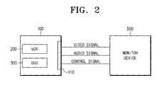
- Figure 2 is a block diagram showing how the multi function apparatus having the SCART connector according to an aspect of the present invention is connected to a monitor device.
- the multi function apparatus 100 through a GUI allows users to manipulate the apparatus more conveniently.
- any of the VCR 200 and the DVD 300 which is basically selected to operate, is set as a default in the GUI, and the device set as a default will be operated when an operation command is sent thereto.
- a user may change the default device with the use of the GUI.
- the SCART connector 110 for transmitting a signal for connection to an external equipment such as the monitor device 500 is installed to the multi function apparatus 100, and the mutual communication between the multi function apparatus 100 and the monitor device 500 is ensured through the SCART connector 110.
- the SCART connector 110 installed to the multi function apparatus 100 enables mutual transmission of video signals, audio signals and control signals between the multi function apparatus 100 and the monitor device 500.
- the SCART connector 110 is also known as Per manifest connector or Euroconnetor, and is described in CENELEC EN 50 049-1:1989 standards or IEC 933-1 standards. Commonly, the SCART connector 110 is used for combining of audio and video connectors, and external devices such as the monitor device 500. These connectors and devices are connected through the SCART connector 110 and used for input or output of audio signals, video signals and control signals.
- the signals transmitted to the SCART connector 110 may be changed according to the type of a monitor device 500 connected to the multi function apparatus 100 as shown in Tables 1 to 4.
- Table 1 shows signals to be transmitted to the SCART connector in case of connection to RGB.
- Output Connector Input Connector 1 Audio right out 2 Audio right in 3 Audio left (or mono) out 6 Audio left (or mono) in 4 Audio return 4 Audio return 7 Blue out 7 Blue in 5 Blue return 5 Blue return 11 Green out 11 Green in 9 Green return 9 Green return 15 Red out 15 Red in 13 Red return 13 Red return 16 RGB status out 16 RGB status in 14 RGB status return 14 RGB status return 19 Sync (composite video) out 20 Sync (composite video) in 17 Sync return 18 Sync return 21 Shield 21 Shield 21 Shield
- Table 2 shows signals to be transmitted to the SCART connector in case of connection to S-Video.
- Output Connector Input Connector 1 Audio right out 2 Audio right in 3 Audio left (or mono) out 6 Audio left (or mono) in 4 Audio return 4 Audio return 15 Chrominance out 15 Chrominance in 13 Chrominance return 13 Chrominance return 8 Video status out 8 Video status in 19 Luminance out 20 Luminance in 17 Luminance return 18 Luminance return 21 Shield 21 Shield
- Table 3 shows signals to be transmitted to the SCART connector in case of connection to Composition Video.
- Output Connector Input Connector 1 Audio right out 2 Audio right in 3 Audio left (or mono) out 6 Audio left (or mono) in 4 Audio return 4 Audio return 8 Video status out 8 Video status in 19 Composite video out 20 Composite video in 17 Composite video return 18 Composite video return 21 Shield 21 Shield
- Table 4 shows signals to be transmitted to the SCART connector in case of connection to a Decoder.
- the SCART connector 110 is a 21-pin connector, and the tenth and twelfth pins are reserved pins, not used.
- an operation command for operating the multi function apparatus 100 is transmitted from the monitor device 500 to the multi function apparatus 100 through the tenth pin, which is a reserved pin, among 21 pins of the SCART connector 110.
- the multi function apparatus 100 If receiving the operation command from the monitor device 500 through the tenth pin of the SCART connector 110, the multi function apparatus 100 sends the operation command to one of the devices (VCR 200 or DVD 300) set as a default device in the GUI or to one device (VCR 200 or DVD 300) set in the GUI by a user so that the corresponding device is operated.
- Figure 3 is a flowchart illustrating the method for controlling the multi function apparatus 100 having the SCART connector 110 according to an aspect of the present invention.
- a user gives a recording command with the use of a manipulation key or a remote controller of the monitor device 500 in order to record the information provided by the monitor device 500 using the multi function apparatus 100, and then the recording command from the monitor device 500 is transmitted to the multi function apparatus 100 through the tenth pin of the SCART connector 110 (S600).
- the multi function apparatus determines whether there exists one device that is set in the GUI by a user to conduct the recording function (S610).
- the recording command is transmitted to the device set in the GUI for recording (S640). If a device for recording is not set in the GUI by a user, it is determined whether the VCR 200 and the DVD 300 are in a prepared state for recording (5620).
- the recording command is transmitted to the prepared device (S630, 5640).
- the device set as a default in the GUI receives audio and video signals through corresponding pins of the SCART connector 110 from the monitor device 500 (S660), and the corresponding device then records the data (S670).
- the recording command is transferred to one device through the SCART connector 110 in Figure 3, so the device receiving the recording command conducts the recording function.
- the recording command is transferred to the multi function apparatus 100 through the tenth pin of the SCART connector 110
- the present invention is not limited to the case.
- an operation command transferred to the multi function apparatus 100 through the SCART connector 110 may be changed according to the multi function apparatus 100, and may be one of regenerating command and recording command.
- the multi function apparatus having the SCART connector and its regenerating method
- the multi function apparatus since the multi function apparatus in which a plurality of devices are combined and each device has an independent function, it is possible to distinguish which device should receive an operation command from an external device, so the AV-Link function may be applied to the multi function apparatus.
- a user may easily select through the GUI a device that will conduct the recording function.
Landscapes
- Engineering & Computer Science (AREA)
- Signal Processing (AREA)
- Multimedia (AREA)
- Computer Networks & Wireless Communication (AREA)
- Two-Way Televisions, Distribution Of Moving Picture Or The Like (AREA)
- Selective Calling Equipment (AREA)
Abstract
Description
- The present invention relates to a multi function apparatus having a SCART (Syndicat des Constructeurs d'Appareils Radiorecepteurs et Televiseurs) connector and its control method, and more particularly, to a multi function apparatus having a SCART connector so that an AV-Link may be applied to the apparatus, and its control method.
- An AV-Link is a function that allows an AV device to be connected to external equipments via cables so that various commands may be sent to the AV device from the external equipments without requiring direct manipulation of the AV device, thereby giving convenience to a user.
- An application of an AV device having an AV-link, is a TV which may directly issue an order to an AV device such that the AV device records audio and video information output through the TV.
- Conventionally, an AV device is generally configured to have only one function, such as a DVD or VCD, so that the AV-Link may be easily applied as mentioned above.
- A recent trend is a multi function apparatus having many devices combined, each device having an independent function. If an AV-Link is applied to the multi function apparatus in the same way as the former case, the multi function apparatus may not determine which device should operate according to a command sent from the external equipment. Thus, there have been limitations in applying an AV-Link to the multi function apparatus.
- According to the present invention there is provided an apparatus and method as set forth in the appended claims. Preferred features of the invention will be apparent from the dependent claims, and the description which follows.
- An aspect of the present invention provides a multi function apparatus having a SCART connector so that an AV-Link may be applied to the multifunction apparatus without problems. According to another aspect of the invention, there is provided a method of controlling the apparatus.
- According to an aspect of the present invention, there is provided a multi function apparatus in which a plurality of devices including first and second devices, each having an independent function, are combined, which includes a SCART (Syndicat des Constructeurs d'Appareils Radiorecepteurs et Televiseurs) connector to which a signal for connection to an external device is connected; and a selection unit for transmitting an operation command sent through the SCART connector to any of the first and second devices.
- According to another aspect of the present invention, preferably, but not necessarily, the operation command is transmitted through a tenth pin of the SCART connector.
- According to another aspect of the present invention, the multi function apparatus may further include a menu-processing unit (440) forming GUI (Graphic User Interface) so as to select any device that is to receive the operation command by the selection unit.
- In another aspect of the invention, there is also provided a method for controlling a multi function apparatus in which a plurality of devices including first and second devices, each having an independent function, are combined and in which a SCART connector to which a signal for connection to an external device is connected is provided, wherein the method includes receiving an operation command from the external device through the SCART connector; selecting one device between the first and second devices that is to be operated, and then transmitting the operation command to the selected device; and allowing the device receiving the operation command to conduct the operation.
- According to another aspect of the present invention, preferably, but not necessarily, the selecting the device determines whether the first and second devices are in a prepared state, and then transmits the operation command to a device that is in a prepared state.
- According to another aspect of the present invention, the operation command may be transmitted through a tenth pin of the SCART connector.
- According to another aspect of the invention, the selected device is one between the first and second devices, set in GUI for the operation.
- Additional aspects and/or advantages of the invention will be set forth in part in the description which follows and, in part, will be obvious from the description, or may be learned by practice of the invention.
- These and/or other aspects and advantages of the present invention will be more apparent and more readily appreciated from the following description of the embodiments, taken in conjunction with the accompanying drawings of which:
- Figure 1 is a block diagram showing a multi function apparatus having a VCR and a DVD;
- Figure 2 is a block diagram showing a multi function apparatus having a SCART connector according to an aspect of the present invention connected to a monitor device; and
- Figure 3 is a flowchart illustrating a control method of the multi function apparatus having a SCART connector according to an aspect of the present invention.
-
- Reference will now be made in detail to the embodiments of the present invention, examples of which are illustrated in the accompanying drawings, wherein like reference numerals refer to the like elements throughout. The embodiments are described below to explain the present invention by referring to the figures.
- The matters defined in the description such as a detailed construction and elements are nothing but the ones provided to assist in a comprehensive understanding of the invention. Thus, it is apparent that the present invention can be carried out without those defined matters. Also, well-known functions or constructions are not described in detail since they would obscure the invention in unnecessary detail.
- Figure 1 is a block diagram of a multi function apparatus having a VCR and a DVD, to which an aspect of the present invention is to be applied.
- The
multi function apparatus 100 is configured so that a plurality of devices including first and second devices, each performing an independent function, are combined therein. In this embodiment, themulti function apparatus 100 is provided with aVCR 200 and aDVD 300, as an example. - The
multi function apparatus 100 includes aVCR 200, aDVD 300, aSCART connector 110, aselection unit 410, astorage unit 420, anoutput unit 430 and a menu-processing unit 440. - The VCR 200 includes a
VCR deck 210, avideo signal processor 220, anaudio signal processor 230, aVCR controller 240, adisplay 260, acontrol panel 270, and aremote controller sensor 280. - The
DVD 300 includes aDVD deck 310, aDVD servo 320, aDVD controller 330, and aDVD encoder 340. - Each element of the
VCR 200 and theDVD 300 is well known in the art, and not described in detail here. - The
SCART connector 110 transmits a signal from the outside to theselection unit 410, and the outside signal input through theSCART connector 110 may be a video signal, an audio signal, or a command signal. - The
selection unit 410 receives an output from theDVD encoder 340, an output from the video andaudio signal processors SCART connector 110. Theselection unit 410 selects the signal controlled by and input from theVCR controller 240 and theDVD controller 330, and an output of theselection unit 410 is sent to themenu processing unit 440 and theoutput unit 430. - In this embodiment, if an operation command is input from the
SCART connector 110, theselection unit 410 is provided with device information from thestorage unit 420 and transmits the device information to theVCR controller 240 or to theDVD controller 330. - The device information for only one of the VCR 200 and the
DVD 300, which is to be operated, is stored in thestorage unit 420 so that only one device is operated among a plurality of devices in the multi function apparatus. The device information stored in thestorage unit 420 may be changed as desired by a user. - The
output unit 430 receives signals from theDVD encoder 340, theselection unit 410 and themenu processing unit 440, and then outputs signals related to DVD image, DVD sound, VCR image and VCR sound. - The menu-
processing unit 440 provides a menu having an OSD (On Screen Display) or a GUI (Graphic User Interface) function so that a user may easily recognize the signal input from theselection unit 410. In this embodiment, the menu provided by the menu-processing unit 440 has the GUI function so that the user may choose a device to be operated between the VCR 200 and theDVD 300. - Figure 2 is a block diagram showing how the multi function apparatus having the SCART connector according to an aspect of the present invention is connected to a monitor device.
- Generally, the
multi function apparatus 100 through a GUI allows users to manipulate the apparatus more conveniently. According to one embodiment of the present invention, any of theVCR 200 and theDVD 300, which is basically selected to operate, is set as a default in the GUI, and the device set as a default will be operated when an operation command is sent thereto. A user may change the default device with the use of the GUI. - In an aspect of the present invention, the
SCART connector 110 for transmitting a signal for connection to an external equipment such as themonitor device 500 is installed to themulti function apparatus 100, and the mutual communication between themulti function apparatus 100 and themonitor device 500 is ensured through theSCART connector 110. - As shown in Figure 2, the
SCART connector 110 installed to themulti function apparatus 100 enables mutual transmission of video signals, audio signals and control signals between themulti function apparatus 100 and themonitor device 500. - The SCART
connector 110 is also known as Pertitel connector or Euroconnetor, and is described in CENELEC EN 50 049-1:1989 standards or IEC 933-1 standards. Commonly, theSCART connector 110 is used for combining of audio and video connectors, and external devices such as themonitor device 500. These connectors and devices are connected through theSCART connector 110 and used for input or output of audio signals, video signals and control signals. - The signals transmitted to the
SCART connector 110 may be changed according to the type of amonitor device 500 connected to themulti function apparatus 100 as shown in Tables 1 to 4. - Table 1 shows signals to be transmitted to the SCART connector in case of connection to RGB.
Output Connector Input Connector 1 Audio right out 2 Audio right in 3 Audio left (or mono) out 6 Audio left (or mono) in 4 Audio return 4 Audio return 7 Blue out 7 Blue in 5 Blue return 5 Blue return 11 Green out 11 Green in 9 Green return 9 Green return 15 Red out 15 Red in 13 Red return 13 Red return 16 RGB status out 16 RGB status in 14 RGB status return 14 RGB status return 19 Sync (composite video) out 20 Sync (composite video) in 17 Sync return 18 Sync return 21 Shield 21 Shield - Table 2 shows signals to be transmitted to the SCART connector in case of connection to S-Video.
Output Connector Input Connector 1 Audio right out 2 Audio right in 3 Audio left (or mono) out 6 Audio left (or mono) in 4 Audio return 4 Audio return 15 Chrominance out 15 Chrominance in 13 Chrominance return 13 Chrominance return 8 Video status out 8 Video status in 19 Luminance out 20 Luminance in 17 Luminance return 18 Luminance return 21 Shield 21 Shield - Table 3 shows signals to be transmitted to the SCART connector in case of connection to Composition Video.
Output Connector Input Connector 1 Audio right out 2 Audio right in 3 Audio left (or mono) out 6 Audio left (or mono) in 4 Audio return 4 Audio return 8 Video status out 8 Video status in 19 Composite video out 20 Composite video in 17 Composite video return 18 Composite video return 21 Shield 21 Shield - Table 4 shows signals to be transmitted to the SCART connector in case of connection to a Decoder.
Receiver Connector Decoder Connector 1 Audio right out 2 Audio right in 2 Audio right in 1 Audio right out 3 Audio left out 6 Audio left in 6 Audio left in 3 Audi left out 4 Audio return 4 Audio return 8 Video status in 8 Video status out 19 Baseband out (scrambled) 20 Baseband in 17 Baseband out return 18 Baseband in return 20 Composite video in (unscramble) 19 Composite video out 18 Composite video in return 17 Composite video out return 21 Shield 21 Shield - As seen in Tables 1 to 4, the
SCART connector 110 is a 21-pin connector, and the tenth and twelfth pins are reserved pins, not used. - In this embodiment, an operation command for operating the
multi function apparatus 100 is transmitted from themonitor device 500 to themulti function apparatus 100 through the tenth pin, which is a reserved pin, among 21 pins of theSCART connector 110. - If receiving the operation command from the
monitor device 500 through the tenth pin of theSCART connector 110, themulti function apparatus 100 sends the operation command to one of the devices (VCR 200 or DVD 300) set as a default device in the GUI or to one device (VCR 200 or DVD 300) set in the GUI by a user so that the corresponding device is operated. - Figure 3 is a flowchart illustrating the method for controlling the
multi function apparatus 100 having theSCART connector 110 according to an aspect of the present invention. - Here, the method for controlling the
multi function apparatus 100 having theSCART connector 110 according to an aspect of the present invention is described with reference to Figures 2 and 3. - With the
multi function apparatus 100 and themonitor device 500 being connected through theSCART connector 110, a user gives a recording command with the use of a manipulation key or a remote controller of themonitor device 500 in order to record the information provided by themonitor device 500 using themulti function apparatus 100, and then the recording command from themonitor device 500 is transmitted to themulti function apparatus 100 through the tenth pin of the SCART connector 110 (S600). - If receiving the recording command from the
monitor device 500, the multi function apparatus determines whether there exists one device that is set in the GUI by a user to conduct the recording function (S610). - In operation S610, if there exists the device set in the GUI for recording, the recording command is transmitted to the device set in the GUI for recording (S640). If a device for recording is not set in the GUI by a user, it is determined whether the
VCR 200 and theDVD 300 are in a prepared state for recording (5620). - If only one of the
VCR 200 and theDVD 300 is prepared for recording (for example, if a storage medium such as DVD and CD is loaded on only one device), the recording command is transmitted to the prepared device (S630, 5640). - After that, audio and video signals are received through corresponding pins of the
SCART connector 110 from the monitor device 500 (S660). The device receiving the audio and video signals then records the data (S670). - In operation S630, if both of the
VCR 200 and theDVD 300 are prepared to record (for example, if DVD and CD are loaded on both devices respectively), the recording command is transmitted to one device that is set as a default in the GUI (S630, S650). - After that, the device set as a default in the GUI receives audio and video signals through corresponding pins of the
SCART connector 110 from the monitor device 500 (S660), and the corresponding device then records the data (S670). - As mentioned above, in order to record the data from the
monitor device 500 by using themulti function apparatus 100, the recording command is transferred to one device through theSCART connector 110 in Figure 3, so the device receiving the recording command conducts the recording function. - Here, though it is described that the recording command is transferred to the
multi function apparatus 100 through the tenth pin of theSCART connector 110, the present invention is not limited to the case. For example, an operation command transferred to themulti function apparatus 100 through theSCART connector 110 may be changed according to themulti function apparatus 100, and may be one of regenerating command and recording command. - As described above, in the multi function apparatus having the SCART connector and its regenerating method, since the multi function apparatus in which a plurality of devices are combined and each device has an independent function, it is possible to distinguish which device should receive an operation command from an external device, so the AV-Link function may be applied to the multi function apparatus. In addition, a user may easily select through the GUI a device that will conduct the recording function.
- The foregoing embodiment and advantages are merely exemplary and are not to be construed as limiting of the present invention. The present teaching can be readily applied to other types of apparatuses. Also, the description of the embodiments of the present invention is intended to be illustrative, and not to limit the scope of the claims, and many alternatives, modifications, and variations will be apparent to those skilled in the art.
- Although a few preferred embodiments have been shown and described, it will be appreciated by those skilled in the art that various changes and modifications might be made without departing from the scope of the invention, as defined in the appended claims.
- Attention is directed to all papers and documents which are filed concurrently with or previous to this specification in connection with this application and which are open to public inspection with this specification, and the contents of all such papers and documents are incorporated herein by reference.
- All of the features disclosed in this specification (including any accompanying claims, abstract and drawings), and/or all of the steps of any method or process so disclosed, may be combined in any combination, except combinations where at least some of such features and/or steps are mutually exclusive.
- Each feature disclosed in this specification (including any accompanying claims, abstract and drawings) may be replaced by alternative features serving the same, equivalent or similar purpose, unless expressly stated otherwise. Thus, unless expressly stated otherwise, each feature disclosed is one example only of a generic series of equivalent or similar features.
- The invention is not restricted to the details of the foregoing embodiment(s). The invention extends to any novel one, or any novel combination, of the features disclosed in this specification (including any accompanying claims, abstract and drawings), or to any novel one, or any novel combination, of the steps of any method or process so disclosed.
Claims (20)
- A multi function apparatus (100) in which a plurality of devices (200, 300) are combined, each device having an independent function, the apparatus comprising:a SCART (Syndicat des Constructeurs d'Appareils Radiorecepteurs et Televiseurs) connector (110) to which a signal for connection to an external device (500) is connected; anda selection unit (410) transmitting an operation command sent through the SCART connector (110) to any of the plurality of devices (200, 300).
- The multi function apparatus (100) of claim 1, wherein the operation command is transmitted through a tenth pin of the SCART connector (110).
- The multi function apparatus (100) of claim 1 or 2, further comprising a menu-processing unit (440) creating a GUI (Graphic User Interface) so as to select any of the plurality of devices (200, 300) that is to receive the operation command by the selection unit (410).
- A method for controlling a multi function apparatus (100) in which a plurality of devices (200, 300) are combined, each device having an independent function, and in which a SCART (Syndicat des Constructeurs d'Appareils Radiorecepteurs et Televiseurs) connector (110) to which a signal for connection to an external device (500) is connected, the method comprising:receiving an operation command from the external device (500) through the SCART connector (110);selecting one of the plurality of devices (200, 300) between the plurality of devices (200, 300) that is to be operated, and then transmitting the operation command to the selected device; andallowing the selected device receiving the operation command to conduct an operation.
- The method of claim 4, wherein the selecting of the one device, comprises determining whether the plurality of devices (200, 300) are in a prepared state, and then transmitting the operation command to the device that is in the prepared state.
- The method of claim 4 or 5, wherein the operation command is transmitted through a tenth pin of the SCART connector (110).
- The method of claim 4, 5, or 6, wherein the selected device is one between the plurality of devices (200, 300), set in a GUI for the operation.
- A multi function apparatus (100) having a plurality of devices (200, 300), each device having an independent function, the apparatus comprising:a SCART (Syndicat des Constructeurs d'Appareils Radiorecepteurs et Televiseurs) connector (110) connected to the multi function apparatus (100), said SCART connector (110) receiving a connection signal for connecting to an external device (500); anda selection unit (410) transmitting an operation command sent through the SCART connector (110) to any of the plurality of devices (200, 300).
- The apparatus of claim 8, further comprising a storage unit (420) storing command information of the plurality of devices (200, 300).
- The apparatus of claim 8 or 9, further comprising a menu-processing unit (440) generating a menu allowing a user to recognize the operation command transmitted from the selection unit (410).
- The apparatus of claim 10, wherein the generated menu includes an OSD (On Screen Display) and a GUI (Graphic User Interface).
- The apparatus of any of claims 8 to 11, wherein the operation command transmitted from the external device (500) to the multi function apparatus (100) is transmitted through a tenth pin of the SCART connector (110).
- The apparatus of claim 12, wherein the operation command is transmitted to one of the plurality of devices (200, 300) set as a default device or to one of the plurality of devices (200, 300) selected by a user.
- The apparatus of any of claims 8 to 13, wherein the SCART connector (110) enables mutual transmission of video signals, audio signals and control signals between the multi function apparatus (100) and the external device (500).
- The apparatus of any of claims 8 to 14, wherein the selection unit (410) is provided with command information of the plurality of devices (200, 300).
- A method of controlling a multi function apparatus (100) having a plurality of devices (200, 300), each device having an independent function and said multi function apparatus (100) connected to a SCART (Syndicat des Constructeurs d'Appareils Radiorecepteurs et Televiseurs) connector (110), said SCART connector (110) receiving a signal for connection to an external device (500), the method comprising:receiving an operation command from the external device (500) through the SCART connector (110);determining whether one of the plurality of devices (200, 300) is set as a default device and if determined that one of the plurality of devices (200, 300) is set as the default device transmitting the operation command to the default device; andoperating the default device.
- The method of claim 16, wherein if determined that one of the plurality of devices (200, 300) is not set as the default device, determining a readiness state of the plurality of devices (200, 300) and selecting a ready device as the default device.
- The method of claim 17, wherein the selected device receives the operation command.
- The method of claim 16, 17 or 18, wherein the operation command transmitted from the external device (500) to the multi function apparatus (100) is transmitted through a tenth pin of the SCART connector (110).
- The method of any of claims 16 to 19, wherein the SCART connector (110) enables mutual transmission of video signals, audio signals and control signals between the multi function apparatus (100) and the external device (500).
Applications Claiming Priority (2)
| Application Number | Priority Date | Filing Date | Title |
|---|---|---|---|
| KR1020040045294A KR100602206B1 (en) | 2004-06-18 | 2004-06-18 | Composite device with SCART connector and its control method |
| KR2004045294 | 2004-06-18 |
Publications (1)
| Publication Number | Publication Date |
|---|---|
| EP1608169A1 true EP1608169A1 (en) | 2005-12-21 |
Family
ID=34941294
Family Applications (1)
| Application Number | Title | Priority Date | Filing Date |
|---|---|---|---|
| EP05252952A Withdrawn EP1608169A1 (en) | 2004-06-18 | 2005-05-13 | Multi function apparatus having scart connector and control method thereof |
Country Status (4)
| Country | Link |
|---|---|
| US (1) | US20050281539A1 (en) |
| EP (1) | EP1608169A1 (en) |
| KR (1) | KR100602206B1 (en) |
| CN (1) | CN1710950A (en) |
Families Citing this family (4)
| Publication number | Priority date | Publication date | Assignee | Title |
|---|---|---|---|---|
| JP2006333084A (en) * | 2005-05-26 | 2006-12-07 | Toshiba Corp | Electronic apparatus |
| KR100782019B1 (en) * | 2006-10-27 | 2007-12-06 | 주식회사 한단정보통신 | Serial control module having an interface for serial communication, a set top box communicating through it and a method of communication of the set top box through it |
| KR101342369B1 (en) * | 2007-01-26 | 2013-12-16 | 엘지전자 주식회사 | Signal sink having GUI function, and the operation method thereof |
| CN101118736B (en) * | 2007-07-10 | 2012-08-22 | 康佳集团股份有限公司 | Method for realizing multiple VGA source synchronous monitoring on LCD television set |
Citations (6)
| Publication number | Priority date | Publication date | Assignee | Title |
|---|---|---|---|---|
| EP0817479A2 (en) * | 1996-06-25 | 1998-01-07 | Sony Corporation | Video system control method |
| EP0859510A1 (en) * | 1992-04-08 | 1998-08-19 | Koninklijke Philips Electronics N.V. | Video interconnection system |
| US5915206A (en) * | 1994-11-04 | 1999-06-22 | Thomson Multimedia S.A. | Procedure for the detection of SCART type connections in a home systems network |
| EP1227673A2 (en) * | 2001-01-19 | 2002-07-31 | Itt Manufacturing Enterprises, Inc. | Home entertainment system |
| EP1271945A2 (en) * | 2001-06-21 | 2003-01-02 | Samsung Electronics Co., Ltd. | Video signal generating apparatus |
| WO2003096695A1 (en) * | 2002-05-08 | 2003-11-20 | Koninklijke Philips Electronics N.V. | Control of an av content source component by an av content sink component |
Family Cites Families (18)
| Publication number | Priority date | Publication date | Assignee | Title |
|---|---|---|---|---|
| JPS5558871A (en) | 1978-10-26 | 1980-05-01 | Matsushita Electric Ind Co Ltd | Magnetic recording and reproducing unit for video |
| JPS6174473A (en) | 1984-09-20 | 1986-04-16 | Sony Corp | Television receiver |
| DE3613796A1 (en) | 1986-04-24 | 1987-10-29 | Grundig Emv | TRANSFER OF TELEVISION RECEIVER TUNING DATA TO A CONNECTED VIDEO RECORDER |
| JPH06205313A (en) * | 1992-12-28 | 1994-07-22 | Sony Corp | Av system |
| JPH06205295A (en) * | 1992-12-28 | 1994-07-22 | Sony Corp | Video signal transmitter |
| US5761372A (en) * | 1993-09-03 | 1998-06-02 | Sony Corporation | Recording reservation central control system for one or more VTR's |
| DE69424611T2 (en) * | 1993-09-22 | 2001-01-25 | Sony Corp., Tokio/Tokyo | TV |
| JP3228381B2 (en) * | 1993-10-29 | 2001-11-12 | ソニー株式会社 | AV selector |
| US6529680B1 (en) * | 1996-04-26 | 2003-03-04 | Mitsubishi Digital Electronics America, Inc. | Device for selecting and controlling a plurality of signal sources in a television system |
| KR100203292B1 (en) * | 1996-12-19 | 1999-06-15 | 윤종용 | Super simple reservation recording device |
| JP3870983B2 (en) * | 1997-02-17 | 2007-01-24 | ソニー株式会社 | Electronic device control apparatus and method, and electronic device |
| US6229575B1 (en) * | 1997-03-31 | 2001-05-08 | Compaq Computer Corporation | Computer convergence device controller for managing disparate video sources |
| KR100910125B1 (en) * | 1998-06-17 | 2009-08-03 | 코닌클리케 필립스 일렉트로닉스 엔.브이. | System of Devices and Peripherals |
| JP4310674B2 (en) * | 2000-01-11 | 2009-08-12 | ソニー株式会社 | Method for selecting device connected to electronic apparatus and electronic apparatus equipped with this selection method |
| AU2001263075A1 (en) * | 2000-05-12 | 2001-11-26 | Thomson Licensing S.A. | Apparatus and method for improved device interoperability |
| US6772434B1 (en) * | 2000-05-24 | 2004-08-03 | The Directv Group, Inc. | Device and method for the integrated presentation of a secondary service as a part of a primary service |
| US20020064370A1 (en) * | 2000-06-15 | 2002-05-30 | John Berkheimer | Dual deck multimedia device |
| US20060291799A1 (en) * | 2003-05-05 | 2006-12-28 | Mears Mark G | Method for tuning to an interconnected ieee-1394 compliant device |
-
2004
- 2004-06-18 KR KR1020040045294A patent/KR100602206B1/en not_active Expired - Fee Related
- 2004-11-19 US US10/991,860 patent/US20050281539A1/en not_active Abandoned
-
2005
- 2005-05-13 EP EP05252952A patent/EP1608169A1/en not_active Withdrawn
- 2005-05-17 CN CNA2005100727055A patent/CN1710950A/en active Pending
Patent Citations (6)
| Publication number | Priority date | Publication date | Assignee | Title |
|---|---|---|---|---|
| EP0859510A1 (en) * | 1992-04-08 | 1998-08-19 | Koninklijke Philips Electronics N.V. | Video interconnection system |
| US5915206A (en) * | 1994-11-04 | 1999-06-22 | Thomson Multimedia S.A. | Procedure for the detection of SCART type connections in a home systems network |
| EP0817479A2 (en) * | 1996-06-25 | 1998-01-07 | Sony Corporation | Video system control method |
| EP1227673A2 (en) * | 2001-01-19 | 2002-07-31 | Itt Manufacturing Enterprises, Inc. | Home entertainment system |
| EP1271945A2 (en) * | 2001-06-21 | 2003-01-02 | Samsung Electronics Co., Ltd. | Video signal generating apparatus |
| WO2003096695A1 (en) * | 2002-05-08 | 2003-11-20 | Koninklijke Philips Electronics N.V. | Control of an av content source component by an av content sink component |
Also Published As
| Publication number | Publication date |
|---|---|
| US20050281539A1 (en) | 2005-12-22 |
| KR20050120090A (en) | 2005-12-22 |
| CN1710950A (en) | 2005-12-21 |
| KR100602206B1 (en) | 2006-07-19 |
Similar Documents
| Publication | Publication Date | Title |
|---|---|---|
| US8378791B2 (en) | Image reproduction system and signal processor used for the same | |
| EP2048882A1 (en) | Display apparatus | |
| US7688391B2 (en) | Controller for remotely controlling two or more external devices | |
| US20020040474A1 (en) | Video processing device | |
| CN101507274A (en) | display device | |
| KR101342369B1 (en) | Signal sink having GUI function, and the operation method thereof | |
| US20080080021A1 (en) | Video output apparatus and display apparatus | |
| CN100591107C (en) | Apparatus and method for providing user interface | |
| KR101366316B1 (en) | Signal sink and operation method thereof, and computer-readable recording media for storing computer program for controlling the sink | |
| JP2008109342A (en) | Display device and display system | |
| EP1608169A1 (en) | Multi function apparatus having scart connector and control method thereof | |
| EP1942657A1 (en) | Device control method using an operation screen, and electronic device and system using the method | |
| CN1780407B (en) | Display device and method with optimal external input setting capability | |
| JP3818804B2 (en) | Remote control system for bus connection device and program recording medium | |
| KR20030010985A (en) | combination system outputting signals for controlling exterior devices in response to the status thereof | |
| JP4104300B2 (en) | Multiple equipment control system | |
| CN1326403C (en) | video device | |
| US20080284913A1 (en) | Audio-visual system, reproducing apparatus, and display device | |
| EP1355490A2 (en) | Multifunction video apparatus | |
| EP1944972A2 (en) | Image display device for controlling external device through registration of control ownership and method therefor | |
| KR101288325B1 (en) | Display apparatus and OSD offer method thereof | |
| KR100433519B1 (en) | Apparatus for processing OSD/OSG in the composite system | |
| EP1630763A2 (en) | Switching apparatus, electronic apparatus, data transfer method, and computer product | |
| JP2005159520A (en) | Electronic apparatus | |
| US20050196132A1 (en) | Video recording and reproducing apparatus and communication method thereof |
Legal Events
| Date | Code | Title | Description |
|---|---|---|---|
| PUAI | Public reference made under article 153(3) epc to a published international application that has entered the european phase |
Free format text: ORIGINAL CODE: 0009012 |
|
| 17P | Request for examination filed |
Effective date: 20050602 |
|
| AK | Designated contracting states |
Kind code of ref document: A1 Designated state(s): AT BE BG CH CY CZ DE DK EE ES FI FR GB GR HU IE IS IT LI LT LU MC NL PL PT RO SE SI SK TR |
|
| AX | Request for extension of the european patent |
Extension state: AL BA HR LV MK YU |
|
| AKX | Designation fees paid |
Designated state(s): DE GB NL |
|
| 17Q | First examination report despatched |
Effective date: 20060118 |
|
| GRAP | Despatch of communication of intention to grant a patent |
Free format text: ORIGINAL CODE: EPIDOSNIGR1 |
|
| RIN1 | Information on inventor provided before grant (corrected) |
Inventor name: NA, JAE-HOON,704-1601, SALGUGOL 7DANJI APT. |
|
| STAA | Information on the status of an ep patent application or granted ep patent |
Free format text: STATUS: THE APPLICATION IS DEEMED TO BE WITHDRAWN |
|
| 18D | Application deemed to be withdrawn |
Effective date: 20100623 |