EP1608143A1 - Image output control system, image processing apparatus, and method thereof - Google Patents
Image output control system, image processing apparatus, and method thereof Download PDFInfo
- Publication number
- EP1608143A1 EP1608143A1 EP04724126A EP04724126A EP1608143A1 EP 1608143 A1 EP1608143 A1 EP 1608143A1 EP 04724126 A EP04724126 A EP 04724126A EP 04724126 A EP04724126 A EP 04724126A EP 1608143 A1 EP1608143 A1 EP 1608143A1
- Authority
- EP
- European Patent Office
- Prior art keywords
- pixel group
- dot
- image
- pixels
- pixel
- Prior art date
- Legal status (The legal status is an assumption and is not a legal conclusion. Google has not performed a legal analysis and makes no representation as to the accuracy of the status listed.)
- Withdrawn
Links
Images












Classifications
-
- H—ELECTRICITY
- H04—ELECTRIC COMMUNICATION TECHNIQUE
- H04N—PICTORIAL COMMUNICATION, e.g. TELEVISION
- H04N1/00—Scanning, transmission or reproduction of documents or the like, e.g. facsimile transmission; Details thereof
- H04N1/40—Picture signal circuits
- H04N1/405—Halftoning, i.e. converting the picture signal of a continuous-tone original into a corresponding signal showing only two levels
- H04N1/4051—Halftoning, i.e. converting the picture signal of a continuous-tone original into a corresponding signal showing only two levels producing a dispersed dots halftone pattern, the dots having substantially the same size
-
- H—ELECTRICITY
- H04—ELECTRIC COMMUNICATION TECHNIQUE
- H04N—PICTORIAL COMMUNICATION, e.g. TELEVISION
- H04N1/00—Scanning, transmission or reproduction of documents or the like, e.g. facsimile transmission; Details thereof
- H04N1/40—Picture signal circuits
- H04N1/405—Halftoning, i.e. converting the picture signal of a continuous-tone original into a corresponding signal showing only two levels
- H04N1/4055—Halftoning, i.e. converting the picture signal of a continuous-tone original into a corresponding signal showing only two levels producing a clustered dots or a size modulated halftone pattern
- H04N1/4057—Halftoning, i.e. converting the picture signal of a continuous-tone original into a corresponding signal showing only two levels producing a clustered dots or a size modulated halftone pattern the pattern being a mixture of differently sized sub-patterns, e.g. spots having only a few different diameters
Definitions
- the present invention relates to a technique of making image data subjected to a preset series of image processing and outputting a processed image. More specifically the invention pertains to a technique of quickly transferring processed image data to an image output device, so as to attain high-speed image output.
- Image output devices that create dots on various output media, for example, printing media and liquid crystal screens, to express an image are widely used as the output device of diverse imaging equipment.
- the image output device divides an image into a number of small elements called pixels and creates dots in these pixels.
- Each pixel takes only either of two states, that is, a dot-on state and a dot-off state.
- the image as a whole may have areas of dense dot formation and areas of sparse dot formation. Each image is thus expressed by varying the dot formation density. For example, in the case of formation of dots with black ink on white printing paper, the areas of dense dot formation express dark areas, whereas the areas of sparse dot formation express bright areas.
- the areas of dense dot formation express bright areas, whereas the areas of sparse dot formation express dark areas. Adequate regulation of the dot formation density enables output of a multi-tone image.
- Control data of the dot formation density is obtained by a preset series of image processing of object image data, which represents an object image to be output.
- the image-processed data is supplied to the image output device, which then creates dots in pixels specified by the supplied data. Dots are accordingly created at adequate densities on an output medium to express a resulting image.
- the higher picture quality and the larger size of output images have been demanded for such image output devices.
- One effective measure to the better-quality demand divides an image into smaller pixels. Size reduction of pixels makes dots created in these small pixels inconspicuous and thereby enhances the picture quality of a resulting image (see, for example, Japanese Patent Laid-Open Gazette No. 2000-115716).
- the size expansion demand is fulfilled, on the other hand, by increasing the total number of pixels. Size expansion of individual pixels naturally expands the size of an output image, but undesirably lowers the picture quality of the output image.
- the effective measure to the size expansion demand thus increases the total number of pixels.
- the image output device receives control data of dot formation and outputs an image according to the received control data.
- the increase in number of pixels included in one image thus undesirably extends the time required for data supply and interferes with high-speed image output.
- the object of the invention is to provide a technique of accelerating supply of control data for dot formation to an image output device and thereby attaining high-speed image output.
- the present invention is directed to an image output system having an image processing device that makes image data subjected to a preset series of image processing and an image output device that creates dots according to a result of the preset series of image processing to output an image.
- the image processing device includes: a pixel group setting module that collects a predetermined number of plural pixels, among a large number of pixels constituting the image, to each pixel group; a dot number specification module that causes image data of respective pixels in each pixel group to be represented uniformly by preset representative image data and specifies number of dots to be created in each pixel group according to the representative image data; and a number data output module that outputs dot number data representing the specified number of dots with regard to each pixel group to the image output device.
- the image output device includes: a number data receiving module that receives the output dot number data with regard to each pixel group; a priority order specification module that specifies a priority order of pixels for dot formation in each pixel group; a pixel position determination module that determines position of each dot-on pixel included in each pixel group, based on the received dot number data and the specified priority order; and a dot formation module that actually creates a dot at the determined position of each dot-on pixel.
- the present invention is thus directed to an image output method that makes image data subjected to a preset series of image processing and creates dots according to a result of the preset series of image processing to output an image.
- the image output method includes: a first step of collecting a predetermined number of plural pixels, among a large number of pixels constituting the image, to each pixel group; a second step of causing image data of respective pixels in each pixel group to be represented uniformly by preset representative image data and specifying number of dots to be created in each pixel group according to the representative image data; a third step of specifying a priority order of pixels for dot formation in each pixel group; a fourth step of determining position of each dot-on pixel included in each pixel group, based on the specified number of dots and the specified priority order; and a fifth step of actually creating a dot at the determined position of each dot-on pixel.
- the image output system and the corresponding image output method of the invention collect a predetermined number of plural pixels to each pixel group.
- Each pixel group may be generated by gathering a plurality of existing pixels, by gathering a plurality of smaller pixel divisions of one identical pixel, which is divided for resolution enhancement of the image, or by gathering plural pixels generated for size expansion of the image.
- the image output system and the image output method specify the number of dots to be created in each pixel group, specify the priority order of pixels for dot formation in the pixel group, determine the position of each dot-on pixel in the pixel group, based on the specified priority order and the specified number of dots with regard to the pixel group, and actually create a dot at the determined position of each dot-on pixel.
- the image data of the respective pixels in each pixel group are represented uniformly by the representative image data.
- This arrangement ensures extremely high-speed specification of the dot number in each pixel group.
- the position of each dot-on pixel in each pixel group is determined, based on the specified number of dots and the specified priority order of the pixel group. This accordingly ensures high-speed determination of the dot-on pixel positions.
- Selection of the priority order for dot formation with regard to each pixel group desirably prevents appearance of any specific pattern and thus keeps the high picture quality of an output image.
- One preferable procedure processes each original pixel of the image to generate multiple pixels having identical image data with image data of the original pixel, so as to increase a total number of pixels in the image, and collects the multiple pixels generated from an identical original pixel to one pixel group.
- This arrangement ensures output of a high-quality image, because of the following reason.
- the position of each dot-on pixel in each pixel group is determined, based on the specified number of dots and the specified priority order of pixels in the pixel group. This pixel position determination technique does not take into account the potential effects of different image data among the respective pixels gathered to one pixel group.
- Determination of dot formation or no-dot formation in the respective pixels of each pixel group is, however, affected by a variation in image data among the respective pixels, as well as by the priority order of the respective pixels representing the tendency of dot formation.
- a significant variation of the image data among the respective pixels in one pixel group may hinder adequate determination of the dot-on pixel positions.
- Collection of multiple pixels generated from an identical original pixel to one pixel group enables all the multiple pixels to have identical image data in the pixel group. This arrangement enables adequate determination of the dot-on pixel positions in each pixel group based on the specified number of dots and the specified priority of pixels in the pixel group, thus ensuring output of a high-quality image.
- the dot number data representing the number of dots to be created in each pixel group occupies a significantly smaller data capacity, compared with the dot on-off state data representing the dot on-off state of individual pixels included in each pixel group. Conversion of the image data into the dot number data of respective pixel groups thus reduces the required volume of data transfer and attains quick data transfer. Even when an object image has a large number of pixels, this arrangement completes data transfer within a short time period and thus enables high-speed image output.
- the positions of dot-on pixels in each pixel group are determined, based on the specified number of dots and one priority order selected with regard to the pixel group among stored multiple priority orders. Even when identical dot numbers are specified for a sequence of adjacent pixel groups, this technique enables dots to be created at different pixel positions in the respective pixel groups. This avoids dot formation in a regular pattern and thereby prevents deterioration of the picture quality of a resulting image.
- one preferable embodiment stores multiple mappings for conversion of the representative image data of each pixel group into the number of dots to be created in the pixel group.
- the embodiment selects one mapping for each pixel group among the stored multiple mappings, and specifies the number of dots to be created in each pixel group, based on the representative image data of the pixel group and the selected mapping.
- This arrangement ensures output of a high-quality image, because of the following reason.
- the image data of the respective pixel groups are converted into different dot numbers. While respective pixel groups have only integral numbers of dots, the average dot number of the area may be an integral value or non-integral value. The value representing the average dot number may be varied continually according to the occurrence frequencies of the dot numbers in the respective pixel groups. Adequate setting of the multiple mappings thus enables conversion of the image data into the adequate dot number data of the area, thus ensuring output of a high-quality image.
- Another advantage of this arrangement based on the selected mapping is easy specification of the number of dots to be created in each pixel group without identifying the respective pixels included in the pixel group.
- the multiple mappings applied for conversion of image data into dot number data may be multiple threshold value sequences.
- Each threshold value sequence consists of plural threshold values corresponding to the predetermined number of plural pixels included in each pixel group.
- the procedure selects one threshold value sequence among the stored multiple threshold value sequences, and sets the number of smaller threshold values in the selected threshold value sequence that are smaller than the image data of each pixel group, to the number of dots to be created in the pixel group.
- the plural threshold values of each threshold value sequence may be stored together with information on an order of magnitude of the respective threshold values in the threshold value sequence.
- the procedure refers to the order of magnitude and compares the image data of each pixel group with the plural threshold values of the selected threshold value sequence, so as to specify the number of dots to be created in the pixel group.
- the comparison shows that a threshold value of an N-th ordinal number of magnitude in a threshold value sequence is smaller than the image data of one pixel group and that a threshold value of an (N+1)-th ordinal number of magnitude in the threshold value sequence is greater than the image data of the pixel group.
- the procedure can specify the number N of smaller threshold values in the threshold value sequence that are smaller than the image data without further comparison of the image data with the remaining threshold values. This means that N dots are to be created in the pixel group.
- each threshold value sequence includes a number of threshold values (for example, 20 threshold values)
- storage of the information on the order of magnitude of the respective threshold values in each threshold value sequence enables specification of the dot number according to the following procedure.
- the procedure first compares the image data with a threshold value having a middle ordinal number of magnitude (for example, a threshold value having a 10 th ordinal number). When the image data is smaller than this selected threshold value, there is no need of comparison between the image data and larger threshold values than the threshold value having the 10 th ordinal number.
- the procedure then compares the image data with a threshold value having a middle ordinal number of magnitude among the smaller threshold values than the threshold value having the 10 th ordinal number, for example, a threshold value having a 5 th ordinal number when a threshold value having a 1 st ordinal number is the smallest threshold value.
- a threshold value having a middle ordinal number of magnitude among the smaller threshold values than the threshold value having the 10 th ordinal number for example, a threshold value having a 5 th ordinal number when a threshold value having a 1 st ordinal number is the smallest threshold value.
- the image data is thus compared with threshold values having 6 th to 9 th ordinal numbers of magnitude.
- the procedure performs the comparison based on the information on the order of magnitude of the respective threshold values in each threshold value sequence and thus quickly specifies the number of dots to be created in each pixel group.
- the information on the order of magnitude of the respective threshold values in each threshold value sequence may be ordinal numbers of magnitude allocated to the respective threshold values.
- the plural threshold values of each threshold value sequence may be arranged in the order of magnitude, for example, in an ascending order or in a descending order.
- This arrangement desirably ensures easy storage of the information on the order of magnitude of the respective threshold values without consumption of any additional memory capacity.
- the following procedure enables quick specification of the dot number in each pixel group.
- comparison with the image data of the pixel group may be performed in a descending order of the plural threshold values in the selected threshold value sequence.
- comparison with the image data of the pixel group may be performed in an ascending order of the plural threshold values of the selected threshold value sequence.
- the procedure starts comparison from the largest threshold value for the large image data, while starting comparison from the smallest threshold value for the small image data. This arrangement ensures quick specification of the number of dots to be created in each pixel group.
- comparison between the image data of each pixel group and the plural threshold values of the selected threshold value sequence may start from a threshold value having a selected ordinal number corresponding to a most recently specified dot number.
- image data varies gradually.
- the number of dots to be created in one pixel group is thus not significantly different from the number of dots to be created in an adjacent pixel group.
- the number of dots to be created in a subsequently processed pixel group is generally close to N.
- the start of comparison from a threshold value having an N-th ordinal number of magnitude or an adjoining ordinal number desirably enables quick specification of the dot number.
- Another preferable embodiment stores a simplified dither matrix that includes the multiple threshold value sequences arranged in a preset two-dimensional array, as the multiple mappings, and selects one threshold value sequence corresponding to a position of each pixel group in the image, among the multiple threshold value sequences stored in the simplified dither matrix.
- Adequate arrangement of the multiple threshold value sequences enables adequate distribution of the dot numbers to be created in the respective pixel groups and thus ensures output of a high-quality image.
- the multiple priority orders representing the tendency of dot formation in each pixel group may also be stored in the form of a matrix.
- This embodiment stores a priority order matrix including the multiple priority orders of pixels for dot formation in each pixel group in a preset two-dimensional array. It is desirable that the simplified dither matrix and the priority order matrix have an identical number of rows and an identical number of columns expressed by the number of pixels.
- An image size is generally larger than the size of a matrix.
- One matrix is thus gradually shifted in position on the image and is repeatedly applied to image processing.
- Different sizes of the simplified dither matrix and the priority order matrix vary the positional relation between the simplified dither matrix and the priority order matrix by each shift on the image. This may lead to unstable image processing and worsen the picture quality.
- the identical sizes of the simplified dither matrix and the priority order matrix keep the fixed positional relation by any shift on the image, thus ensuring stable image processing and desirable picture quality.
- the dot number specification process stores the simplified dither matrix.
- the simplified dither matrix is generated by dividing a dither matrix, which maps threshold values to respective pixels arranged in a two-dimensional array, into multiple groups corresponding to multiple pixel groups, and includes the multiple threshold value sequences arranged corresponding to the multiple groups.
- the pixel position determination process stores the multiple priority orders representing the tendency of dot formation in the form of a priority order matrix.
- the priority order matrix is generated by dividing the dither matrix into the multiple groups corresponding to the multiple pixel groups and includes the multiple priority orders arranged corresponding to the multiple groups.
- the priority order is specified with regard to each pixel group based on a magnitude order of respective threshold values included in a corresponding group.
- the pixel position determination process selects one priority order corresponding to a position of each pixel group in the image, among the multiple priority orders stored in the priority order matrix, and determines the position of each dot-on pixel according to the selected priority order.
- both the dot number specification module and the pixel position determination module may store the identical dither matrix and execute the respective processes according to the dither matrix.
- Another application to attain the object of the invention is an image processing device that causes input image data representing an image to go through a preset series of image processing and thereby generates control data, which is used for control of dot formation by an image output device that creates dots and outputs a resulting processed image.
- the image processing device includes: a pixel group setting module that collects a predetermined number of plural pixels, among a large number of pixels constituting the image, to each pixel group; a dot number specification module that causes image data of respective pixels in each pixel group to be represented uniformly by preset representative image data and specifies number of dots to be created in each pixel group according to the representative image data; and a number data output module that outputs dot number data representing the specified number of dots with regard to each pixel group as the control data to the image output device.
- the present invention is thus directed to an image processing method that causes input image data representing an image to go through a preset series of image processing and thereby generates control data, which is used for control of dot formation by an image output device that creates dots and outputs a resulting processed image.
- the image processing method includes the steps of: (A) collecting a predetermined number of plural pixels, among a large number of pixels constituting the image, to each pixel group; (B) causing image data of respective pixels in each pixel group to be represented uniformly by preset representative image data and specifying number of dots to be created in each pixel group according to the representative image data; and (C) outputting dot number data representing the specified number of dots with regard to each pixel group as the control data to the image output device.
- the image processing device and the corresponding image processing method of the invention collect a predetermined number of plural pixels to each pixel group, specify the number of dots to be created in each pixel group, and output dot number data representing the specified number of dots as the control data.
- the dot number data representing the number of dots to be created in each pixel group occupies a significantly smaller data capacity, compared with the dot on-off state data representing the dot on-off state of individual pixels included in each pixel group. Even when an object image has a large number of pixels, this technique ensures quick data transfer to the image output device and resulting high-speed image output.
- Collection of multiple pixels generated from an identical original pixel to one pixel group enables all the multiple pixels to have identical image data in the pixel group. This arrangement enables adequate determination of the dot-on pixel positions in each pixel group, thus ensuring output of a high-quality image, as discussed above.
- the image processing device and the corresponding image processing method of the invention may store multiple mappings for conversion of image data into the dot number and select one mapping with regard to each pixel group among the stored multiple mappings to convert the image data of the pixel group into the number of dots to be created in the pixel group.
- Adequate setting of the multiple mappings enables adequate conversion of the image data into the dot number data, thus ensuring output of a high-quality image.
- the technique of the invention may be actualized by programs that are executed by the computer to attain the image output method and the image processing method described above, as well as by recording media in which such programs are recorded.
- One application of the invention is a program corresponding to the image output method discussed above.
- the present invention is thus directed to an image output program that is executed by a computer to make image data subjected to a preset series of image processing, create dots according to a result of the preset series of image processing, and thereby output an image.
- the image output program causes the computer to attain: a first function of collecting a predetermined number of plural pixels, among a large number of pixels constituting the image, to each pixel group; a second function of causing image data of respective pixels in each pixel group to be represented uniformly by preset representative image data and specifying number of dots to be created in each pixel group according to the representative image data; a third function of specifying a priority order of pixels for dot formation in each pixel group; a fourth function of determining position of each dot-on pixel included in each pixel group, based on the specified number of dots and the specified priority order; and a fifth function of actually creating a dot at the determined position of each dot-on pixel.
- the second function has the functions of: storing multiple mappings for conversion of the representative image data of each pixel group into the number of dots to be created in the pixel group; and selecting one mapping for each pixel group among the stored multiple mappings.
- the second function specifies the number of dots to be created in each pixel group, based on the representative image data of the pixel group and the selected mapping.
- Another application of the invention is a program corresponding to the image processing method discussed above.
- the present invention is thus directed to an image processing program that is executed by a computer to make image data of an image subjected to a preset series of image processing and thereby generate control data, which is used for control of dot formation by an image output device that creates dots and outputs a resulting processed image.
- the image processing program causes the computer to attain the functions of: (A) collecting a predetermined number of plural pixels, among a large number of pixels constituting the image, to each pixel group; (B) causing image data of respective pixels in each pixel group to be represented uniformly by preset representative image data and specifying number of dots to be created in each pixel group according to the representative image data; and (C) outputting dot number data representing the specified number of dots with regard to each pixel group as the control data to the image output device.
- the technique of the invention may also be actualized by recording media in which such programs are recorded in a computer readable manner.
- the computer reads any of such programs, which may be recorded in the recording media, to attain the various functions described above. This ensures high-speed image output even when an object image has a large number of pixels.
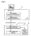
- Fig. 1 schematically illustrates a printing system to explain the general outline of the invention
- Fig. 2 illustrates the configuration of a computer as an image processing device of an embodiment
- Fig. 3 schematically illustrates the structure of a printer as an image output device of the embodiment
- Fig. 4 shows an arrangement of nozzles Nz on respective ink ejection heads
- Fig. 5 is a flowchart showing an image printing routine executed by the image processing device of a first embodiment
- Figs. 6(a) and 6(b) show resolution conversion of image data
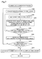
- Fig. 7 is a flowchart showing the details of a number data generation process executed in the first embodiment
- Fig. 8 shows part of a dither matrix
- Fig. 9 shows a process of determining dot on-off state of individual pixels by referring to the dither matrix
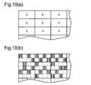
- Figs. 10(a) and 10(b) conceptually show a process of generating dot number data with regard to each pixel group
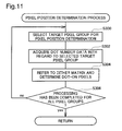
- Fig. 11 is a flowchart showing the details of a pixel position determination process executed in the first embodiment
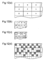
- Figs. 12(a) through 12(d) show a process of determining the positions of dot-on pixels according to the dot number data in the pixel position determination process of the first embodiment
- Figs. 13(a) through 13(c) show a process of generating dot number data in a number data generation process of a first modified example of the first embodiment
- Figs. 14(a) through 14(c) show a process of determining the positions of dot-on pixels according to the dot number data in a pixel position determination process of a second modified example of the first embodiment
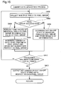
- Fig. 15 is a flowchart showing the details of a number data generation process executed in a second embodiment
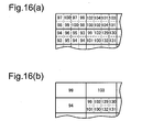
- Figs. 16(a) and 16(b) show replacement of tone values of individual pixels included in one pixel group with a mean tone value according to the presence or the absence of an edge in the pixel group;
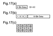
- Figs. 17(a) through 17(c) show data formats output from the computer in the second embodiment
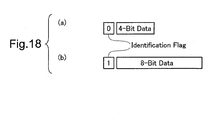
- Fig. 18 shows another data format output from the computer in the second embodiment
- Fig. 19 is a flowchart showing the details of a pixel position determination process executed in the second embodiment
- Fig. 20 is a flowchart showing an image printing routine executed in a third embodiment
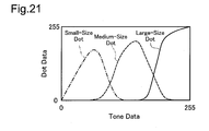
- Fig. 21 conceptually shows a conversion table referred to in a conversion process to large-size, medium-size, and small-size dot data in the third embodiment
- Figs. 22(a) and 22(b) show a process of generating dot number data from dot data in a number data generation process of the third embodiment
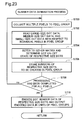
- Fig. 23 is a flowchart showing the details of the number data generation process executed in the third embodiment
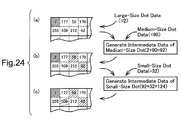
- Fig. 24 shows a process of determining the positions of dot-on pixels of respective size dots by referring to the dither matrix
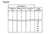
- Fig. 25 conceptually shows a conversion table referred to for encoding dot number data of the respective size dots
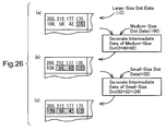
- Fig. 26 conceptually shows a process of determining the numbers of the respective size dots without specification of dot-on pixel positions in the number data generation process of the third embodiment
- Fig. 27 is a flowchart showing the details of a pixel position determination process executed in the third embodiment
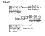
- Fig. 28 shows a process of determining the positions of dot-on pixels of the respective size dots according to the dot number data in the pixel position determination process of the third embodiment
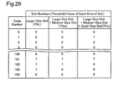
- Fig. 29 conceptually shows a decoding table referred to in the pixel position determination process of the third embodiment
- Fig. 30 is a flowchart showing the details of a number data generation process executed in an image printing process of a first modified example
- Fig. 31 shows a process of unequivocally determining the numbers of respective size dots according to a mean tone value in each pixel group
- Fig. 32 is a flowchart showing the details of a number data generation process executed in an image printing process of a second modified example
- Fig. 33 is a flowchart showing the details of a pixel position determination process executed in an image printing process of a third modified example.
- Fig. 34 shows storage of multiple priority orders for individual pixels included in each pixel group.
- Fig. 1 schematically illustrates the configuration of a printing system as one mode of an image output control system of the invention.
- the printing system includes a computer 10 as an image processing device and a printer 20 as an image output device.
- the computer 10 loads and executes preset programs and works in combination with the printer 20 as the integral printing system.
- the printer 20 creates dots on a printing medium to print an image.
- the computer 10 makes image data, which represent an object image to be printed, subjected to a preset series of image processing to generate and supply control data to the printer 20, which then controls dot formation in respective pixels according to the received control data.
- the computer converts image data into dot on-off state data representing the dot on-off state in respective pixels constituting an object image and supplies the dot on-off state data to the printer.
- the printer creates dots according to the received dot on-off state data to complete a printed image.
- An increasing number of pixels included in an object image to be printed naturally leads to an increasing volume of the dot on-off state data of the respective pixels.
- the increased data volume undesirably extends the time required for data transfer from the computer to the printer and thereby the total printing time.
- the computer 10 accordingly has a dot number specification module and a number data generation module to execute the following series of processing.
- the dot number specification module collects a predetermined number of plural pixels, among a large number of pixels constituting the image, to each pixel group and specifies the number of dots to be created in each pixel group according to image data.
- the dot number data in each pixel group is generated by dividing image data into pixel groups and determining the dot on-off state in each of the pixel groups. Another applicable procedure may convert image data into data representing the dot on-off state, collect every predetermined number of multiple pixels to one pixel group, and determine the number of dots to be created in each pixel group.
- the predetermined number of multiple pixels collected to one pixel group may not be mutually adjacent pixels.
- the number data generation module sends the dot number data generated with respect to each of the pixel groups to the printer 20.
- the printer 20 shown in Fig. 1 has a priority order storage module, a pixel position determination module, and a dot formation module.
- the priority order storage module stores multiple options for the priority order of pixels in each pixel group to create dots therein.
- the pixel position determination module refers to the priority order storage module and determines the positions of dot-on pixels, where dots are to be created, in each pixel group.
- a concrete procedure of the pixel position determination receives dot number data with respect to one pixel group and chooses one from the multiple options for the priority order of pixels stored in the priority order storage module. The procedure then selects a certain number of pixels specified by the dot number data as dot-on pixels according to the chosen priority order, among the predetermined number of multiple pixels included in the pixel group.
- the pixel position determination module receives the dot number data, chooses the priority order of pixels in each pixel group, and determines the positions of dot-on pixels.
- the dot formation module actually creates dots in the dot-on pixels thus determined.
- a resulting image is accordingly recorded on a printing medium.
- the computer 10 supplies the dot number data representing the number of dots to be created in each pixel group, instead of the dot on-off state data of individual pixels, to the printer 20.
- This arrangement desirably reduces the total volume of data supply, compared with the structure of supplying the dot on-off state data of individual pixels. Even when an image includes a large number of pixels, this arrangement ensures quick data supply from the computer 10 to the printer 20 and thereby enables high-speed printing of a resulting image.
- Fig. 2 illustrates the configuration of a computer 100 as an image processing device in a first embodiment.
- the computer 100 is a known computer including a CPU 102, a ROM 104, and a RAM 106 interconnected via a bus 116.
- the computer 100 has a disk controller DDC 109 to read data from, for example, a flexible disk 124 or a compact disc 126, a peripheral equipment interface PIF 108 to receive and send data from and to peripheral equipment, and a video interface VIF 112 to drive and actuate a CRT 114.
- the PIF 108 is connected with a color printer 200 described later and a hard disk unit 118. Connection of a digital camera 120 or a color scanner 122 with the PIF 108 enables printing of images taken by the digital camera 120 or the color scanner 122. Insertion of a network interface card NIC 110 to the computer 100 causes the computer 100 to connect with a communication line 300 and obtain data stored in a storage device 310 linked to the communication line 300.
- Fig. 3 schematically illustrates the structure of the color printer 200 in this embodiment.
- the color printer 200 is an inkjet printer that is capable of creating dots of four color inks, cyan, magenta, yellow, and black.
- the inkjet printer may be capable of creating dots of six color inks, cyan ink of a lower dye density (light cyan ink) and magenta ink of a lower dye density (light magenta ink), in addition to the above four color inks.
- cyan ink, magenta ink, yellow ink, black ink, light cyan ink, and light magenta ink may be expressed simply as C ink, M ink, Y ink, K ink, LC ink, and LM ink, respectively.
- the color printer 200 has a mechanism of actuating a print head 241 mounted on a carriage 240 to eject inks and create dots, a mechanism of activating a carriage motor 230 to move the carriage 240 back and forth along a shaft of a platen 236, a mechanism of activating a paper feed motor 235 to feed printing paper P, and a control circuit 260 that controls the formation of dots, the shift of the carriage 240, and the feed of the printing paper P.
- An ink cartridge 242 for storing the K ink and an ink cartridge 243 for storing the C, M, and Y inks are attached to the carriage 240.
- the respective inks in the ink cartridges 242 and 243 attached to the carriage 240 are supplied through non-illustrated ink conduits to corresponding ink ejection heads 244 through 247 of the respective colors formed on the bottom face of the print head 241.
- Fig. 4 shows an arrangement of inkjet nozzles Nz on the respective ink ejection heads 244 through 247.
- Four nozzle arrays for ejecting the C, M, Y, and K color inks are formed on the bottom face ofthe respective ink ejection heads 244 through 247.
- Each nozzle array includes 48 nozzles Nz arranged at a fixed nozzle pitch 'k'.
- the control circuit 260 includes a CPU, a ROM, and a RAM interconnected via a bus.
- the control circuit 260 controls the operations of the carriage motor 230 and the paper feed motor 235 to regulate main scans and sub-scans of the carriage 240, while controlling ejection of ink droplets from the respective nozzles at adequate timings according to print data supplied from the computer 100.
- the color printer 200 creates ink dots of the respective colors at adequate positions on a printing medium under control of the control circuit 260 and thereby prints a resulting color image.
- any of diverse methods may be applied to eject ink droplets from the ink ejection heads of the respective colors.
- Typical examples of the available technique include a method that uses piezoelectric elements for ejection of ink droplets and a method that uses heaters located in respective ink conduits to generate bubbles in the ink conduits for ejection of ink droplets.
- the technique of the invention is also applicable to printers that take advantage of thermal transfer to create ink dots on a printing medium and printers that take advantage of static electricity to make toners of respective colors adhere to a printing medium, in addition to the inkjet printers.
- the carriage motor 230 is driven to move the ink ejection heads 244 through 247 of the respective colors in a main scanning direction relative to the printing paper P, while the paper feed motor 235 is actuated to feed the printing paper P in a sub-scanning direction.
- the control circuit 260 repeats main scans and sub-scans of the carriage 240 and drives nozzles at adequate timings to eject ink droplets according to print data.
- the color printer 200 thus prints a resulting color image on the printing paper P.
- Fig. 5 is a flowchart showing an image printing routine executed by the computer 100 and the printer 200 in the system of the embodiment, so as to make object image data subjected to a preset series of image processing and print a processed image on a printing medium.
- the first half of the image printing routine is performed by the CPU of the computer 100, whereas the latter half is performed by the CPU of the control circuit 260 in the printer 200.
- the image printing process of the embodiment is described below with reference to the flowchart of Fig. 5.
- the computer 100 first reads object image data to be converted (step S100).
- the object image data are RGB color image data in this embodiment, although monochromatic image data may be replaced with the color image data.
- the input color image data goes through a color conversion process (step S102).
- the color conversion process converts the RGB color image data expressed by combinations of tone values of the colors R, G, and B into image data expressed by combinations of tone values of respective colors used for printing.
- the printer 20 prints an image with the four color inks C, M, Y, and K.
- the color conversion process of this embodiment accordingly converts the image data expressed by the tone values of the colors R, G, and B into image data expressed by the tone values of the four colors C, M, Y, and K.
- the procedure of color conversion refers to a three-dimensional numerical table called a color conversion table (LUT).
- the LUT stores a mapping of the tone values of the respective colors C, M, Y, and K to the RGB color image data and thus facilitates and accelerates the color conversion.
- the color-converted image data then goes through a resolution conversion process (step S104).
- the resolution conversion process converts the resolution of the image data into a resolution for printing with the printer 200 (printing resolution).
- size reduction of pixels to attain printing at the higher resolution effectively enhances the picture quality of resulting prints.
- the increased resolution of original image data is, however, not essential for the increased printing resolution.
- the dot printing technique takes only either of a dot-on state or a dot-off state with respect to each pixel. Even in the case of variable-size dot printing, only several tones are expressible in each pixel.
- the input image data of, for example, 1 byte, on the other hand, can express 256 tones with respect to each pixel.
- step S 104 in the flowchart of Fig. 5 converts the resolution of the input image data into the higher printing resolution.
- Figs. 6(a) and 6(b) show an example of the resolution conversion process executed in the first embodiment.
- the prior color conversion gives the image data of the C, M, Y, and K colors.
- the resolution conversion process discussed below is applied to the image data in any of these colors. For the simplicity of explanation, the color is not specified in the following description.
- Fig. 6(a) shows part of image data after color conversion.
- the color-converted image data has tone values allocated to the respective pixels arranged in lattice.
- Each rectangle in Fig. 6(a) represents a pixel, and the numeral in the rectangle denotes a tone value allocated to the pixel.
- One available method to increase the resolution of the image data creates new pixels by interpolation of existing pixels.
- the resolution conversion process of this embodiment adopts the simplest technique of dividing each pixel into smaller pixels.
- Fig. 6(b) shows division of pixels for conversion of the resolution.
- each pixel is divided into four in the main scanning direction (the horizontal direction in the drawing) and into two in the sub-scanning direction (the vertical direction in the drawing). Namely one pixel is divided into eight smaller pixels.
- the broken lines in each solid rectangle of Fig. 6(b) represent divisions of each pixel.
- the tone value given to the original pixel is allocated to all the smaller divisions of the pixel.
- Such division of pixels quadruples the resolution of the image data in the main scanning direction and doubles in the sub-scanning direction.
- the multiplication of resolution may be set arbitrarily according to the requirements.
- the computer 100 After conversion ofthe input resolution into the printing resolution, the computer 100 starts a number data generation process (step S106).
- the color-converted image data are tone data having tone values allocated to the respective pixels.
- the printer 200 creates dots at adequate densities on pixel positions to print an image.
- the required procedure accordingly converts the tone data into dot on-off state data of the respective pixels and transfers the dot on-off state data to the printer 200.
- Output of the dot on-off state data in units of individual pixels to the printer 200 undesirably extends the time required for data transfer with an increase in number of pixels and thereby impedes high-speed image printing.
- the image printing process of this embodiment collects every predetermined number of multiple pixels to one pixel group and transfers dot number data representing the number of dots to be created in each pixel group to the printer 200 in units of pixel groups.
- the dot number data representing the number of dots to be created in each pixel group may be obtained by converting image data into dot on-off state data of respective pixels and then collecting every predetermined number of multiple pixels to one pixel group.
- Another applicable procedure may first collect every predetermined number of multiple pixels to one pixel group and then determine the number of dots to be created in each pixel group as discussed later.
- the number data generation process of step S106 generates the dot number data representing the number of dots to be created in each pixel group and transfers the generated dot number data to the printer 20. The details of the number data generation process will be discussed later.
- the CPU of the control circuit 260 in the printer 200 receives the dot number data supplied from the computer 100 and starts a pixel position determination process (step S 108).
- the computer 100 supplies the dot number data that represent the number of dots to be created in each pixel group, instead of the dot on-off state data of respective pixels.
- the pixel position determination process determines the positions of dot-on pixels in each pixel group, based on the received dot number data with respect to the pixel group. The details of the pixel position determination process will be discussed later.
- the printer 200 After determination of the positions of dot-on pixels, the printer 200 actually creates dots at the dot-on pixel positions thus determined (step S110). As discussed previously with reference to Fig. 3, while repeating the main scans and the sub-scans of the carriage 240, the printer 200 drives and actuates the ink ejection heads to eject the ink droplets and thereby create ink dots on the printing paper. A resulting image corresponding to image data is thus printed on the printing paper.
- Fig. 7 is a flowchart showing the details of the number data generation process executed in the first embodiment. The details of the number data generation process are described with reference to this flowchart.
- the number data generation process first collects a predetermined number of multiple pixels to a pixel group (step S200).
- the precedent resolution conversion process has divided one pixel into eight smaller pixels.
- the eight smaller pixels obtained by division of one pixel are thus collected to one pixel group.
- one pixel on the upper left corner of Fig. 6(a) is divided into eight smaller pixels arranged vertically in four columns and horizontally in two rows on the upper left corner of Fig. 6(b). These eight smaller pixels constitute one pixel group.
- the predetermined number of multiple pixels collected to one pixel group may not be mutually adjacent pixels, but may be any pixels having a specified positional relation.
- the resolution conversion process may be omitted from the image printing routine of Fig. 5.
- the terminology 'pixel group' in the following description is to be replaced by 'the pixel prior to resolution conversion'.
- the number data generation process subsequently sets one object pixel for determination of the dot on-off state (target pixel) among the predetermined number of multiple pixels collected to one pixel group (step S202).
- the process compares the tone value allocated to the target pixel with a threshold value stored at the corresponding position in a dither matrix to determine the dot on-off state with respect to the target pixel (step S204).
- the dither matrix is a two-dimensional numerical table that stores multiple threshold values arranged in lattice. The procedure of determining the dot on-off state based on a dither matrix is described with reference to Figs. 8 and 9. Fig. 8 shows part of a dither matrix.
- This dither matrix stores threshold values, which are selected at random throughout a tone value range of 1 to 255 and are allocated to a total of 4096 pixels of 64 pixels in length and 64 pixels in width.
- the image data are 1-byte data and the tone value allocated to each pixel is in the range of 0 to 255, so that the threshold values in the dither matrix are selected in the tone value range of 1 to 255.
- the dither matrix is not restricted to the size of 64 pixels in both length and width as in the example of Fig. 8, but may have any desired size having different numbers of pixels in length and in width or having the same numbers of pixels in both length and width.
- Fig. 9 conceptually shows determination of the dot on-off state with respect to each target pixel, based on the dither matrix.
- the procedure of determining the dot on-off state first compares the tone value of each target pixel with a threshold value stored at the corresponding position in the dither matrix.
- Each arrow of thin broken line in Fig. 9 represents comparison between the tone value of each target pixel and a threshold value stored at the corresponding position in the dither matrix.
- the process determines formation of a dot in the target pixel.
- the process determines formation of no dot in the target pixel.
- the tone value allocated to a pixel on the upper left corner of image data is '97'
- the threshold value stored at the corresponding position in the dither matrix is '1'. Namely the process determines formation of a dot in this pixel.
- Each arrow of solid line in Fig. 9 represents a process of determining formation of a dot in a target pixel and writing the result of determination at a corresponding position in a memory.
- An adjacent pixel on the right side of the upper left pixel also has the tone value '97', while the corresponding threshold value in the dither matrix is '177'.
- the threshold value is greater than the tone value, so that the process determines formation of no dot in this pixel.
- the process refers to the dither matrix and determines formation or no-formation of a dot in the target pixel at step S204 in the flowchart of Fig. 7.
- the number data generation process determines whether the above series of processing has been completed with respect to all the pixels in the pixel group (step S206). When the pixel group still has any unprocessed pixel (step S206: no), the process returns to step S202 and repeats the subsequent series of processing.
- the process detects the number of dots to be created in the pixel group as dot number data and stores the dot number data with respect to the processed pixel group into the memory (step S208).
- three pixels are determined as dot-on pixels in the pixel group on the upper left corner of the image data. Namely the dot number data representing the dot number '3' is stored into the memory.
- the process After conclusion of the processing with regard to one pixel group, the process subsequently determines whether the processing has been completed with regard to all the pixels included in image data (step S210). When there is any unprocessed pixel, the process returns to step S200 to set a next pixel group, repeats the subsequent series of processing to generate dot number data with regard to the next pixel group, and stores the dot number data (step S208). When the processing has been completed with regard to all the pixels in the image data (step S210: yes), the process outputs the dot number data stored in units of pixel groups to the printer 200 (step S212). Here terminates the number data generation process shown in Fig. 7.
- Fig. 10(a) conceptually shows dot number data obtained by the number data generation process discussed above.
- Each of multiple rectangles represents a pixel group, and the numeral shown in each pixel group denotes storage of the number of dots to be created in the pixel group.
- the computer 100 converts color-converted image data into dot number data as shown in Fig. 10(a) and outputs only the dot number data stored with respect to each pixel group to the printer 200.
- Output of only the dot number data desirably reduces the data volume and thus ensures higher-speed data output, compared with the procedure of outputting the dot on-off state data of individual pixels, as discussed below.
- Fig. 10(b) shows the dot on-off state of respective pixels in multiple pixel groups.
- the thin broken lines in Fig. 10(b) show that each pixel group consists of multiple pixels.
- Each square filled with slant lines represents a dot-on pixel where a dot is to be created.
- the computer 100 outputs the dot on-off state data of individual pixels as shown in Fig. 10(b) to the printer 200.
- each pixel takes only either of the two states, that is, the dot-on state or the dot-off state.
- the data volume required for each pixel is accordingly 1 bit. Since each pixel group consists of eight pixels, the data volume output to the printer 200 is 8 bits with respect to each pixel group.
- the procedure of this embodiment outputs the dot number data representing the number of dots to be created in each pixel group.
- the number of dots to be created in one pixel group varies in the range of 0 to 8.
- the dot number data with respect to each pixel group thus requires only 4 bits. This desirably halves the data volume, compared with output of the dot on-off state data of individual pixels. Output of the dot number data in units of pixel groups thus attains high-speed data transfer to the printer 200.
- the dot number data transferred from the computer 100 go through the pixel position determination process executed by the printer 200 to be converted into the dot on-off state data of individual pixels, as discussed below.
- Fig. 11 is a flowchart showing the details of the pixel position determination process executed in the image printing routine of the first embodiment.
- the CPU of the control circuit 260 in the printer 200 receives the dot number data transferred in units of pixel groups from the computer 100 and executes the pixel position determination process.
- Fig. 12 conceptually shows conversion of the dot number data representing the number of dots to be created in each pixel group into the dot on-off state data of individual pixels by the pixel position determination process. The details of the pixel position determination process are described below with reference to Figs. 11 and 12.
- the pixel position determination process first selects a target pixel group as an object of processing (step S300 in the flowchart of Fig. 11) and acquires the dot number data representing the number of dots to be created in the selected target pixel group (step S302).
- Fig. 12(a) conceptually shows the dot number data transferred in units of pixel groups from the computer 100. In this illustrated example, a pixel group on the upper left corner is selected as a target pixel group going through the pixel position determination process. The process acquires the dot number data '3' as the number of dots to be created in the selected target pixel group at step S302 in Fig. 11.
- the process subsequently refers to a priority order of pixels in the target pixel group for dot formation and determines dot-on pixels (step S304).
- the dither matrix is used to set the priority order of dot formation.
- threshold values are set at respective pixel positions in the dither matrix. Determination of the dot on-off state in one pixel compares the tone value of image data allocated to the pixel with a threshold value at the corresponding position in the dither matrix. When the tone value is greater than the threshold value, the pixel is determined as a dot-on pixel. The pixel having the smaller setting of the threshold value in the dither matrix has the greater tendency of dot formation. The dither matrix is thus assumed to show the priority order of respective pixels for dot formation.
- the procedure of this embodiment takes advantage of the characteristics of the dither matrix and uses the dither matrix to set the priority order of pixels in the target pixel group for dot formation.
- the pixel group on the upper left corner is selected as the target pixel group to be processed.
- the procedure reads threshold values in the dither matrix stored at corresponding positions of the respective pixels included in the selected target pixel group.
- Fig. 12(b) shows threshold values read from the corresponding pixel positions in the dither matrix shown in Fig. 8. Dots are created in the order of pixels having the smaller threshold values. The number of dots to be created in the currently processed target pixel group is 3 as shown in Fig. 12(a). The positions of dot-on pixels are determined according to the priority order of pixels for dot formation as shown in Fig. 12(c). In this illustrated example of Fig.
- the pixel of the smallest threshold value surrounded by the solid line, the pixel of the second smallest threshold value surrounded by the broken line, and the pixel of the third smallest threshold value surrounded by the one-dot chain line are determined as dot-on pixels.
- step S306 After determination of the positions of dot-on pixels in the target pixel group selected as the object of processing, it is determined whether the processing has been completed with regard to all the pixel groups (step S306 in the flowchart of Fig. 11). When there is any unprocessed pixel group (step S306: no), the pixel position determination process returns to step S300 to set a next pixel group and repeats the subsequent series of processing with respect to the next pixel group.
- the dot number data representing the number of dots to be created in each pixel group as shown in Fig. 12(a) are accordingly converted to the dot on-off state data of individual pixels as shown in Fig. 12(d).
- the squares filled with slant lines in Fig. 12(d) represent the dot-on pixels.
- step S306: yes the program exits from the pixel position determination process shown in Fig. 11 and returns to the image printing routine of Fig. 5.
- the computer 100 transfers the dot number data representing the number of dots to be created in each pixel group to the printer 200, instead of the dot on-off state data of the individual pixels. This arrangement significantly reduces the total volume of data transfer. Even when an image includes a large number of pixels, the procedure of the first embodiment ensures quick data transfer and high-speed image printing.
- the dither matrix referred to in the number data generation process executed by the computer 100 is identical with the dither matrix referred to in the pixel position determination process executed by the printer 200.
- Such setting ensures complete restoration of the positions of dot-on pixels even in the case of transfer of only the dot number data from the computer 100 to the printer 200.
- the positions of dot-on pixels based on the determination of the dot on-off state of the individual pixels executed by the computer 100 are perfectly matched with the positions of dot-on pixels determined by the printer 200. This proves complete restoration of the positions of dot-on pixels.
- the arrangement of the first embodiment thus enables the printer 200 to accurately determine the positions of dot-on pixels, while ensuring quick transfer of the dot number data from the computer 100 to the printer 200. This leads to high-speed printing of a high-quality image.
- the procedure of the first embodiment may be modified in various ways. Some examples of possible modification are discussed briefly below.
- the number data generation process of the first embodiment converts image data into dot on-off state data of individual pixels, further converts the dot on-off state data into dot number data representing the number of dots to be created in each pixel group, and transfers the dot number data to the printer 200.
- the computer 100 determines the dot on-off state with specification of dot-on pixel positions.
- the information on specification of dot-on pixel positions is, however, omitted from the transferred data, and only the information on the number of dots to be created in each pixel group is transferred to the printer 200.
- the number data generation process executed in a first modified example thus generates only the dot number data representing the number of dots to be created in each pixel group without specification of dot-on pixel positions.
- Fig. 13 shows the outline of the number data generation process executed in the first modified example.
- Fig. 13 (a) shows a simplified dither matrix referred to in the number data generation process of the first modified example.
- the standard dither matrix referred to in the number data generation process of the first embodiment has the settings of threshold values corresponding to respective pixel positions (see Fig. 8).
- threshold values are not one-to-one mapped to the respective pixel positions but are collectively mapped to the respective pixel groups. Namely a set of multiple threshold values is one-to-one mapped to one pixel group.
- the number of multiple threshold values mapped to each pixel group is identical with the number of multiple pixels included in each pixel group.
- a set of eight threshold values ⁇ 255,212,177,170,109,58,42,1 ⁇ is mapped to a pixel group on the upper left corner of the simplified dither matrix.
- another set of eight threshold values ⁇ 242,223,186,161,79,70,48,5 ⁇ is mapped to an adjacent pixel group on the right side.
- the number data generation process of the first modified example compares the image data in each pixel group with a corresponding set of threshold values and thereby determines the number of dots to be created in each pixel without specification of dot-on pixel positions.
- target image data to be processed is identical with the example of image data processed in the first embodiment (see Fig. 6(b)).
- all the pixels have an identical tone value '97'.
- the pixel group at the corresponding position in the simplified dither matrix stores the set of eight threshold values ⁇ 255,212,177,170,109,58,42,1 ⁇ .
- threshold values ⁇ 58,42,1 ⁇ are smaller than the tone value '97' of the pixel group. Namely three dots are to be created in this pixel group. Part of the threshold values are surrounded by the broken line in Fig. 13(b). This shows that these threshold values are smaller than the tone value of the pixel group.
- the set of multiple threshold values are stored corresponding to each pixel group and are compared with the tone value of the pixel group. This procedure readily determines the number of dots to be created in the pixel group without specifying the dot-on pixel positions in the pixel group. This series of processing is repeated for all the pixel groups and determines the numbers of dots to be created in the respective pixel groups as shown in Fig. 13 (c).
- the simplified dither matrix referred to in the first modified example is equivalent to the standard dither matrix referred to in the first embodiment.
- Each set of multiple threshold values stored corresponding to each pixel group in the simplified dither matrix of Fig. 13 is obtained by gathering threshold values stored at respective pixel positions in the dither matrix of Fig. 8 to one pixel group.
- Such equivalency of the simplified dither matrix to the standard dither matrix gives the same result of the dot number specification based on the simplified dither matrix without specification of dot-on pixel positions as the result of the dot number specification based on the standard dither matrix with specification of dot-on pixel positions.
- the procedure of the first modified example determines the number of dots to be created in each pixel group by simple comparison between the set of multiple threshold values stored corresponding to each pixel group and the tone value of the image data in the pixel group. This arrangement does not require comparison between the threshold values and the tone values of the image data at individual pixel positions in each pixel group, thus more quickly generating the dot number data representing the number of dots to be created in each pixel group.
- the procedure of the first modified example specifies only the number of the threshold values that are smaller than the tone value of the image data in each pixel group. Arrangement of the threshold values in the order of magnitude in each pixel group further enhances the processing speed.
- the tone value of the image data is equal to '97', while the set of the threshold values are arranged in the order of magnitude ⁇ 255,212,177,170,109,58,42,1 ⁇ .
- These threshold values may be arranged either in a descending order or in an ascending order.
- the tone value of the image data varies in the range of 0 to 255, so that the tone value '97' is relatively small.
- This relatively small tone value is thus compared with the threshold values in the ascending order.
- the tone value '97' is first compared with the smallest threshold value '1' and is determined to be greater than the threshold value '1'.
- the tone value '97' is then compared with the adjacent second-smallest threshold value '42' and is also determined to be greater than the threshold value '42'.
- the tone value '97' is subsequently compared with the adjacent third-smallest threshold value '58'. In this manner, the tone value is successively compared with the threshold values in the ascending order.
- the tone value '97' is compared with the threshold value '109' and is determined to be smaller than the threshold value '109'.
- the threshold values in one pixel group are arranged in the order of magnitude, it is obvious that the subsequent threshold values are greater than the tone value once the threshold value exceeds the tone value. No further comparison is accordingly required.
- each pixel group stores eight threshold values, the dot number data is obtained by comparison of the tone value with only the four threshold values in this pixel group.
- the tone value of the image data is compared with the threshold values in the descending order. For example, when the tone value of the image data is '200' in the above example, the comparison with the tone value starts from the largest threshold value '255' and then goes to the adjacent second-largest threshold value '212', and the adjacent third-largest threshold value '177'.
- the dot number data in the pixel group is obtained by comparison of the tone value with only these three threshold values.
- storage of the threshold values in the order of magnitude in each pixel group ensures quick determination of the number of dots to be created in the pixel group.
- the pixel position determination process of the first embodiment discussed above receives the dot number data representing the number of dots to be created in each pixel group, refers to the dither matrix, and determines the positions of dot-on pixels in each pixel group (see Fig. 12).
- the threshold values of the individual pixels are, however, not essential for determination of the positions of dot-on pixels according to the dot number data.
- the only requirement is a priority order of the respective pixels in each pixel group for dot formation.
- the pixel position determination process in a second modified example refers to a matrix storing a priority order of pixels (hereafter referred to as the priority order matrix), instead of the dither matrix, to determine the positions of dot-on pixels.
- Fig. 14 conceptually shows determination of the positions of dot-on pixels according to a priority order matrix in the pixel position determination process of the second modified example.
- Fig. 14(a) shows a priority order matrix.
- Each rectangle of the thick solid line represents a pixel group.
- Each pixel group is divided into eight pixels as shown by the thin broken lines.
- the numerals shown in the respective pixels denote a priority order of the pixels in each pixel group for dot formation (that is, an order of dot formation).
- the dot number data used for the description of this example are those shown in Fig. 12(a) and are identical with the dot number data used for the description of the pixel position determination process in the first embodiment.
- the dot number data of Fig. 12(a) the number of dots to be created in a pixel group on the upper left corner is 3.
- the procedure of the second modified example accordingly selects three pixels having first to third priority numbers in the upper left pixel group of the priority order matrix shown in Fig. 14(a) and determines the positions of dot-on pixels.
- Fig. 14(b) shows such selection of three pixels to determine the positions of dot-on pixels.
- the solid lines surrounding the numerals in the pixels mean that the pixels are selected. This series of processing is repeated with regard to all the pixel groups to determine all the positions of dot-on pixels as shown in Fig. 14(c).
- the squares filled with slant lines in Fig. 14(c) represent dot-on pixels.
- the procedure of this modified example compares the priority number of each pixel included in a selected target pixel group with the dot number data representing the number of dots to be created in the pixel group. Selection of pixels having the priority numbers of not greater than the dot number data readily determines the positions of dot-on pixels in the pixel group. This method does not need to count up the number of pixels selected for dot formation according to the dot number data, thus facilitating determination of the positions of dot-on pixels.
- the largest value stored in the priority order matrix (that is, the largest priority number allocated to the pixel) is the number of pixels included in one pixel group and is thus significantly smaller than the threshold values stored in the dither matrix. Namely the priority order matrix occupies a remarkably smaller storage capacity than the dither matrix.
- the printer executing the pixel position determination process may not have a sufficient storage capacity.
- the use of the priority order matrix to determine the positions of dot-on pixels advantageously saves the storage capacity of the printer.
- the priority order matrix shown in Fig. 14(a) corresponds to the dither matrix referred to in the number data generation process for determination of the dot on-off state in the respective pixels.
- the threshold values set in the dither matrix represent the priority order of dot formation.
- the priority order set in the priority order matrix shown in Fig. 14(a) is identical with the ascending order of the threshold values in the dither matrix allocated to the respective pixels in the pixel group. Setting the priority order matrix corresponding to the dither matrix referred to in the number data generation process ensures adequate determination of the positions of dot-on pixels according to the priority order matrix.
- the positions of dot-on pixels determined according to the priority order matrix are completely matched with the positions of dot-on pixels according to the determination of the dot on-off state of the individual pixels. This proves adequate determination of the positions of dot-on pixels according to the priority order matrix.
- the number data generation process is required to specify only the number of dots to be created in each pixel group and does not demand information on the positions of dot-on pixels, that is, information regarding which pixels in each pixel group are dot-on pixels.
- the number data generation process may thus refer to the simplified dither matrix to generate the dot number data, instead of the standard dither matrix.
- the number data generation process based on the standard dither matrix specifies not only the number of dots to be created in each pixel group but the positions of dot-on pixels. Omission of the information on the positions of dot-on pixels from the standard dither matrix gives the simplified dither matrix.
- the modified number data generation process based on the simplified dither matrix thus specifies only the number of dots to be created in each pixel group.
- the pixel position determination process receives the dot number data representing the number of dots to be created in each pixel group and is required to determine only the positions of dot-on pixels.
- the pixel position determination process may thus refer to the priority order matrix to determine the positions of dot-on pixels, instead of the standard dither matrix. Omission of the information used for specification of the number of dots to be created in each pixel group from the dither matrix gives the priority order matrix.
- Both the simplified dither matrix and the priority order matrix have less information volumes than the standard dither matrix.
- the combination of the simplified dither matrix and the priority order matrix gives the equivalent volume of information to that of the standard dither matrix.
- a simplified dither matrix and a priority order matrix can be generated corresponding to an original standard dither matrix of any arrangement.
- the generation of the dot number data according to the simplified dither matrix and the subsequent determination of the positions of dot-on pixels according to the priority order matrix ensure formation of dots in the identical arrangement with the result of dot formation according to the original standard dither matrix.
- the procedure of the first embodiment discussed above divides one pixel into multiple smaller pixels and gathers the multiple smaller pixels as divisions of an identical original pixel to a pixel group. Division of one pixel into multiple smaller pixels is required, for example, when an image is printed at a higher resolution than the resolution of input image data.
- the respective pixels included in one pixel group have an identical tone value.
- the technique of the invention is, however, also applicable to a pixel group of multiple pixels having different tone values. For example, when the printing resolution is set identical with the resolution of the input image data and one pixel group includes multiple pixels of image data, the multiple pixels included in the pixel group may have different tone values.
- one pixel group may include smaller pixels as divisions of different original pixels.
- the multiple pixels included in one pixel group may have different tone values.
- Fig. 15 is a flowchart showing a number data generation process executed in the second embodiment. Like the number data generation process of the first embodiment, the number data generation process of the second embodiment is executed by the CPU of the computer 100 in the course of the image printing process shown in Fig. 5.
- the number data generation process of the second embodiment first collects a predetermined number of multiple pixels to one pixel group (step S400).
- each pixel group includes eight pixels, that is, two rows in the horizontal direction and four columns in the vertical direction. This is only illustrative and not restrictive at all, and each pixel group may include any number of rows and any number of columns.
- the number data generation process determines whether the pixel group includes an edge (step S402).
- the procedure of this embodiment determines that the pixel group includes an edge when a tone difference between a largest tone value and a smallest tone value among the tone values allocated to the multiple pixels included in the pixel group is not less than a preset level.
- This method is, however, not restrictive at all, and any other suitable method is applicable to detection of an edge.
- step S402 When it is determined that no edge is included in the pixel group (step S402: no), the process calculates a mean tone value of the pixel group and replaces the tone values of the respective pixels in the pixel group with the calculated mean tone value (step S404).
- the respective pixels included in one pixel group accordingly have an identical tone value.
- the number of dots to be created in the pixel group is thus determined according to the same procedure as the first embodiment described above.
- Fig. 16 shows replacement of the tone values of the respective pixels in each pixel group with the mean tone value in the case of detection of no edge in the pixel group.
- Fig. 16(a) shows tone values allocated to respective pixels in pixel groups.
- a pixel group on the upper left corner has a maximum tone value '100' and a minimum tone value '97'.
- a lower right pixel group on the other hand, has a maximum tone value '132' and a minimum tone value '99'.
- One concrete procedure presets an adequate threshold value (for example, a tone value '20') and detects the presence of an edge in one pixel group when the tone difference in the pixel group is greater than the preset threshold value.
- the procedure detects no edge in the pixel group when the tone difference in the pixel group is smaller than the preset threshold value.
- the procedure calculates the mean tone value of the pixel group and replaces the tone values of all the pixels included in the pixel group with the calculated mean tone value.
- Fig. 16(b) shows replacement of the tone values of the respective pixels included in one pixel group with the calculated mean tone value, in response to detection of no edge in the pixel group.
- the upper left pixel group, an adjacent pixel group on the right, and another adjacent pixel group immediately below have relatively small tone differences. All the pixels in the respective pixel groups are thus replaced by the individually calculated mean tone values '99', '103', and '94'.
- all the pixels in the pixel group have the identical tone value. The process thus determines the number of dots to be created in such a pixel group according to the procedure of the first embodiment discussed above (step S406 in the flowchart of Fig.
- the lower right pixel group has a relatively large tone difference of '33', which detects the presence of an edge.
- the process does not replace the tone values with the mean tone value in this pixel group but compares the tone values of the individual pixels in the pixel group with the corresponding threshold values in the dither matrix to determine the dot on-off state of the respective pixels (see Fig. 9) and stores the results of determination regarding the dot on-off state of the respective pixels (step S408 in Fig. 15).
- step S410 the process subsequently determines whether the processing has been completed with regard to all the pixels included in image data (step S410). When there is any unprocessed pixel (step S410: no), the process returns to step S400 to set a next target pixel group of multiple pixels and repeats the subsequent series of processing. When all the pixels have been collected to pixel groups and processed (step S410: yes), the process outputs the dot number data, which have been stored at step S406, with regard to the pixel groups with no edge to the printer 200, while outputting the dot on-off state data of individual pixels, which have been stored at step S408, with regard to the pixel groups with an edge to the printer 200 (step S412).
- the dot number data of the respective pixel groups and the dot on-off state data of the individual pixels in the pixel groups are simultaneously output to the printer 200.
- the number data generation process of the second embodiment outputs these data in the following formats to discriminate the dot number data from the dot on-off state data of the individual pixels.
- Fig. 17 shows the formats of the data output from the computer 100 to the printer 200 in the second embodiment.
- the dot number data representing the number of dots to be created in each pixel group are output as 4-bit data with regard to each pixel group as shown in Fig. 17(a).
- Each pixel group includes eight pixels, so that the dot number varies only in the range of 0 to 8.
- the data capacity of 4 bits is thus sufficient to express the number of dots.
- the dot on-off state data representing the dot on-off state of the individual pixels are output in the format shown in Fig. 17(b).
- the first four bits express a value selected in a range of 9 to 15 (the value '9' in the illustrated example of Fig.
- the subsequent eight bits express the settings of the dot on-off state of the individual pixels. Since the dot number varies only in the range of 0 to 8, setting the value of or over 9 in the 4-bit data head means that the subsequent 8-bit data does not show the dot number but represents the dot on-off state of the individual pixels.
- the respective bits of the 8-bit data may be allocated to the individual pixels, for example, in an order of Fig. 17(c).
- the dot on-off state data representing the dot on-off state of respective pixels in each pixel group are output in this format. In the case of application of the formats of Fig. 17 to the data output, 4-bit dot number data are transferred to the printer 200 with regard to the pixel groups with no edge, while 12-bit dot on-off state data are transferred to the printer 200 with regard to the pixel groups with an edge.
- the identification bit set equal to '0' means that subsequent 4-bit data is dot number data as shown in Fig. 18(a)
- the identification bit set equal to '1' means that subsequent 8-bit data is dot on-off state data of individual pixels as shown in Fig. 18(b).
- 5-bit dot number data are transferred to the printer 200 with regard to the pixel groups with no edge
- 9-bit dot on-off state data are transferred to the printer 200 with regard to the pixel groups with an edge.
- the volume of data transfer according to the method of Fig. 17 is less than that according to the method of Fig. 18.
- the volume of data transfer according to the method of Fig. 18 is less than that according to the method of Fig. 17.
- the method of Fig. 18 with the identification bit is suitable for the data transfer.
- the method of Fig. 17 is suitable for the data transfer.
- the pixel groups with an edge generally occupy a relatively low ratio, so that the method of Fig. 17 is preferable to attain the quicker data transfer.
- the dot number data of the respective pixel groups and the dot on-off state data of the individual pixels are simultaneously output to the printer 200 at step S412 in the flowchart of Fig. 15.
- the program exits from the number data generation process of the second embodiment shown in Fig. 15 and returns to the image printing routine.
- the dot number data and the dot on-off state data of the individual pixels are sent simultaneously from the computer 100.
- the printer 200 determines the positions of dot-on pixels according to the following method. In the description below, it is assumed that the formats of Fig. 17 are adopted for the data transfer.
- Fig. 19 is a flowchart showing a pixel position determination process executed in the second embodiment to determine the positions of dot-on pixels.
- the pixel position determination process first inputs data of the 4-bit volume (step S500) and determines whether the input 4-bit data represents a value of or over 9 (step S502).
- each pixel group includes eight pixels, and the dot number varies only in the range of 0 to 8.
- the input 4-bit data represents a value of or over 9
- it is determined that the input data is not the dot number data but the subsequent data is dot on-off state data of individual pixels.
- the input 4-bit data represents a value of or below 8
- it is determined that the input data is the dot number data representing the number of dots to be created in one pixel group.
- step S502 When the input 4-bit data does not represent a value of or over 9 (step S502: no), the process regards the input 4-bit data as dot number data and determines the positions of dot-on pixels in the pixel group according to the same procedure as that of the first embodiment (step S504).
- step S502: yes when the input 4-bit data represents a value of or over 9 (step S502: yes), on the other hand, the process reads the subsequent 8-bit data and regards the subsequent 8-bit data as the dot on-off state data of the individual pixels to determine the positions of dot-on pixels (step S506).
- step S508 After determination of the positions of dot-on pixels in one pixel group, it is determined whether the processing has been completed with regard to all the pixel groups (step S508). When there is any unprocessed pixel group, the pixel position determination process returns to step S500 and repeats the subsequent series of processing with respect to a next pixel group. The above series of processing is repeated until the positions of dot-on pixels are determined with regard to all the pixel groups. On conclusion of the processing with regard to all the pixel groups, the program exits from the pixel position determination process of the second embodiment shown in Fig. 19 and returns to the image printing routine.
- the image printing process of the second embodiment executes the number data generation process shown in Figs. 15 through 18 and the pixel position determination process shown in Fig. 19. Even when multiple pixels included in one pixel group have different tone values, the image printing process of the second embodiment transfers the dot number data with regard to the pixel groups with no edge. This arrangement ensures quick data transfer to the printer 200 and thereby high-speed image printing.
- the image printing process of the second embodiment transfers the dot on-off state data of the individual pixels with regard to the pixel groups with an edge.
- An increase in ratio of the pixel groups with an edge extends the time required for data transfer to the printer 200.
- One possible measure elevates the criterion for detection of edges and thereby reduces the potential for edge detection. This shortens the time required for data transfer and thereby enables high-speed image printing.
- the tone values of the individual pixels in the pixel group are replaced with the calculated mean tone value.
- the excessive elevation of the criterion for edge detection (the excessively reduced potential for edge detection) to shorten the time of data transfer may lead to deterioration of the printing quality.
- the printing resolution is typically set higher than the resolution of the input image data. Enhancement of the resolution is attained by division of original pixels into smaller pixels according to the resolution conversion process (step S104 in the flowchart of Fig. 5) or by interpolation for creation of additional pixels. In either case, the tone value gently varies in most pixel groups. In the image with the demand for the high printing quality, no edge is thus detected in most pixel groups even without elevation ofthe criterion for edge detection. This ensures quick data transfer with keeping the demanded high printing quality.
- each pixel takes only either of the two tone values corresponding to the dot-on state and the dot-off state.
- Some printers may, however, be capable of varying the size of dots or varying the density of ink used for dot formation to express a greater number of tone values in individual pixels.
- the technique of the invention is effectively applicable to such multi-valued printers.
- Application of the technique of the invention to a multi-valued printer is described below as a third embodiment.
- Fig. 20 is a flowchart showing an image printing routine executed in the third embodiment.
- the primary difference of the image printing process of the third embodiment from the image printing process of the first embodiment discussed above with reference to Fig. 5 is conversion of color-converted data into large-size, medium-size, and small-size dot data.
- the image printing process of the third embodiment is described below with the focus on such difference.
- the printer 200 is the multi-valued printer that is capable of varying the size of dots.
- the following description is, however, similarly applicable to the multi-valued printer that is capable of varying the density of ink instead of the dot size and to the multi-valued printer that is capable of varying both the dot size and the density of ink.
- the image printing routine of the third embodiment reads object image data to be converted (step S600) and makes the input image data subjected to color conversion (step S602).
- the color conversion process converts the input image data into tone data expressed by the tone values of the respective colors C, M, Y, and K.
- the printer 200 of the first embodiment discussed above is not capable of varying the dot size but takes only either of the two states, the dot-on state or the dot-off state, with regard to each color.
- the image printing process of the first embodiment thus determines the dot on-off state in the individual pixels immediately after the color conversion.
- the printer 200 of the third embodiment is capable of varying the dot size and creating three different size dots, that is, the large-size dot, the medium-size dot, and the small-size dot.
- the image printing process of the third embodiment thus converts the tone data obtained by the color conversion into large-size dot data, medium-size dot data, and small-size dot data with regard to each color (step S604).
- a conversion table shown in Fig. 21 is used for conversion of the tone data into the large-size dot data, the medium-size dot data, and the small-size dot data.
- the conversion table stores variations in large-size dot data, medium-size dot data, and small-size dot data against the tone data.
- the tone data after color conversion is further converted by referring to this conversion table.
- the large-size dot data, the medium-size dot data, and the small-size dot data respectively go through a resolution conversion process (step S606). Any of diverse methods is applicable to the resolution conversion process.
- the technique of dividing original pixels into smaller pixels is adopted for the resolution conversion like the first embodiment.
- the tone value allocated to each original pixel is set to all the smaller pixels as divisions of the original pixel.
- the printer 200 After conversion of the input resolution into the printing resolution, the resolution-converted data goes through a number data generation process (step S608).
- the printer 200 is capable of creating the three different size dots, that is, the large-size dot, the medium-size dot, and the small-size dot.
- the number data generation process of the third embodiment thus generates dot number data with regard to the three different size dots and outputs the generated dot number data to the printer 200.
- Fig. 22 shows a process of generating dot number data from dot data according to the number data generation process of the third embodiment.
- Fig. 22(a) shows settings of dot data with regard to the large-size, medium-size, and small-size dots to the individual pixels included in each pixel group.
- Each solid rectangle represents one pixel group.
- Each pixel group includes a predetermined number of multiple pixels, and dot data are actually set to each of the multiple pixels.
- the individual pixels are omitted from the illustration, and the dot data are set to each pixel group in the illustration.
- the expression of Data(L,M,S) (2,90,32) in a pixel group on the upper left corner of Fig.
- the large-size dot data '2', the medium-size dot data '90', and the small-size dot data '32' are set to the individual pixels included in this pixel group.
- the resolution conversion process may be omitted and the number data generation process may take charge of the substantial resolution conversion.
- the number data generation process of the third embodiment processes the dot data with regard to the respective size dots and generates dot number data as shown in Fig. 22(b).
- each solid rectangle in Fig. 22(b) represents a pixel group, which includes a predetermined number of multiple pixels. The individual pixels are omitted from the illustration, and the dot number data are generated with respect to each pixel group.
- Dot(L,M,S) (1,2,1) in the pixel group on the upper left corner of Fig.
- the dot number data '1', '2', and '1' are generated respectively as the dot numbers of the large-size dot, the medium-size dot, and the small-size dot to be created in this pixel group.
- the details of the number data generation process of the third embodiment will be discussed later.
- the printer 200 receives the dot number data output from the computer 100 and carries out a pixel position determination process (step S610). Since the structure of the third embodiment creates the three different size dots, that is, the large-size dot, the medium-size dot, and the small-size dot, the pixel position determination process determines the positions of dot-on pixels with regard to these three different size dots. The details of the pixel position determination process of the third embodiment will be discussed later.
- the printer 200 repeats the main scans and the sub-scans of the carriage 240 and drives the ink ejection heads to create the large-size dots, the medium-size dots, and the small-size dots on the printing paper (step S612). A resulting image corresponding to image data is thus printed on the printing paper.
- Fig. 23 is a flowchart showing the details of the number data generation process in the third embodiment executed by the CPU of the computer 100.
- the CPU first collects a predetermined number of multiple pixels in the input image data to one pixel group (step S700).
- the resolution conversion process (step S606 in the flowchart of Fig. 20) prior to the number data generation process has divided each original pixel into smaller pixels, as in the procedure of the first embodiment. Multiple smaller pixels as divisions of one identical pixel are thus gathered to one pixel group.
- the process then reads the large-size dot data, the medium-size dot data, and the small-size dot data with respect to the individual pixels in the pixel group (step S702).
- the individual pixels included in the pixel group are divisions of an identical original pixel and have an identical tone value.
- the process may thus read the dot data of only one pixel in the pixel group, instead of reading the dot data of all the individual pixels in the pixel group.
- Fig. 24 shows a method of determining the dot on-off state of the large-size dot, the medium-size dot, and the small-size dot in each target pixel by referring to the dither matrix.
- the dot data to be processed and the dither matrix referred to are respectively those shown in Fig. 22(a) and shown in Fig. 8.
- Fig. 24 shows a process of determining the dot on-off state of the three different size dots in a pixel group on the upper left corner of an image.
- Each rectangle of the thick solid line represents one pixel group, and the divisions of the pixel group by the thin broken lines represent multiple pixels constituting the pixel group.
- the numeral shown in each pixel is a threshold value set at the corresponding position in the dither matrix.
- the method of determining the dot on-off state first compares the large-size dot data with the threshold values set at the corresponding positions in the dither matrix. When the large-size dot data is greater than the corresponding threshold value in a target pixel, a large-size dot is to be created in the target pixel.
- Fig. 24(a) shows determination of the large-size dot on-off state with regard to the individual pixels in the pixel group.
- the large-size dot data is '2' in this pixel group. Only in the upper left pixel having the corresponding threshold value '1' of the dither matrix, the large-size dot data '2' is greater than the threshold value.
- the corresponding threshold values of the dither matrix are greater than the large-size dot data '2' in all the other pixels. Namely only one large-size dot is to be created in this pixel group.
- the pixel having the threshold value '1' of the dither matrix is filled with dense slant lines in Fig. 24(a). This expresses expected formation of a large-size dot in this pixel.
- the method subsequently determines the medium-size dot on-off state.
- the method adds the medium-size dot data to the large-size dot data to generate intermediate data of the medium-size dot and compares the intermediate data of the medium-size dot with the threshold values set at the corresponding positions in the dither matrix.
- the intermediate data of the medium-size dot is greater than the corresponding threshold value in a target pixel, a medium-size dot is to be created in the target pixel.
- the pixel specified for expected formation of a large-size dot is omitted from the object of determination of the medium-size dot on-off state.
- the method determines the small-size dot on-off state.
- the method adds the small-size dot data to the intermediate data of the medium-size dot to generate intermediate data of the small-size dot and compares the intermediate data of the small-size dot with the corresponding threshold values of the dither matrix with respect to the remaining pixels that have not been specified as dot-on pixels.
- the intermediate data of the small-size dot is greater than the corresponding threshold value in a target pixel, a small-size dot is to be created in the target pixel.
- the process determines the dot on-off state of the large-size dot, the medium-size dot, and the small-size dot with respect to the individual pixels in the pixel group in the above manner at step S704 in the flowchart of Fig. 23.
- the process stores the numbers of the respective size dots to be created in the pixel group (step S706).
- the numbers of the respective size dots to be created in the pixel group are stored as the numbers of the respective size dots to be created in the pixel group.
- the process determines whether the processing has been completed with regard to all the pixels included in the input image data (step S708). When there is any unprocessed pixel (step S708: No), the process returns to step S700 to set a next pixel group and repeats the subsequent series of processing. When the processing has been completed with regard to all the pixels included in the input image data (step S708: Yes), the process outputs the numbers of the respective size dots stored in units of pixel groups to the printer 200 (step S710). For further reduction of the data volume output to the printer 200, the dot number data of the respective size dots are encoded as discussed below.
- Fig. 25 conceptually shows a conversion table referred to for encoding the dot number data of the respective size dots.
- the conversion table stores settings of code numbers allocated to respective combinations of the numbers of the large-size dot, the medium-size dot, and the small-size dot. For example, a code number '0' is allocated to a combination of the numbers of the large-size dot, the medium-size dot, and the small-size dot all equal to 0. A code number '1' is allocated to a combination of the number of the small-size dot equal to 1 and the numbers of the large-size dot and the medium-size dot both equal to 0.
- Output of the code number representing the numbers of the respective size dots to the printer 200 desirably reduces the output data volume.
- the reason of data volume reduction is described briefly.
- Each pixel group consists of 8 pixels, and the maximum number of each size dot is accordingly 8.
- the dot number data of each size dot accordingly requires a 4-bit data volume.
- the code numbers range from 0 to 164 as shown in Fig. 25.
- Each pixel group accordingly requires only an 8-bit data volume for the encoded data. Such encoding thus readily reduces the required data volume to 2/3.
- the combinations of the numbers of the respective size dots include many unpractical combinations for actual printing. Allocation of code numbers to these unpractical combinations is naturally not required. Allocation of the code numbers to only practical combinations further reduces the required data volume of each pixel group to be less than 8 bits.
- the process encodes the dot number data of the respective size dots and outputs the encoded data to the printer 200 at step S710 in the flowchart of Fig. 23, on this account.
- the program terminates the number data generation process of the third embodiment and returns to the image printing routine of Fig. 20.
- the number data generation process of the third embodiment discussed above determines the dot on-off state of the respective size dots with specification of dot-on pixel positions.
- the information on specification of dot-on pixel positions is, however, omitted from the transferred data, and only the information on the numbers of the respective size dots to be created in each pixel group is transferred to the printer 200.
- the number data generation process may determine the numbers of the respective size dots without specification of dot-on pixel positions, like the first modified example of the first embodiment described above (see Fig. 13).
- Fig. 26 conceptually shows a process of determining the numbers of the respective size dots without specification of dot-on pixel positions.
- the process of Fig. 26 determines the numbers of the respective size dots without specification of the dot-on pixel positions in the pixel group of Fig. 24.
- a simplified dither matrix is applicable to determine the numbers of multiple different size dots, as in the case of determination of the number of a single size dot.
- the standard dither matrix stores the threshold values one-to-one mapped to the respective pixel positions
- the simplified dither matrix stores the threshold values that are not one-to-one mapped to the respective pixel positions but are collectively mapped to the respective pixel groups. Namely a set of multiple threshold values is one-to-one mapped to one pixel group in the simplified dither matrix.
- the threshold values in the dither matrix are one-to-one mapped to the respective pixels in the pixel group shown in Fig. 24.
- a set of threshold values ⁇ 255,212,177,170,109,58,42,1 ⁇ is one-to-one mapped to the pixel group. The following describes the method of determining the numbers of the respective size dots without specification of dot-on pixel positions according to the example of Fig. 26.
- This modified method sequentially determines the number of the large-size dot, the number of the medium-size dot, and the number of the small-size dot in this order.
- Fig. 26(a) shows determination of the number of the large-size dot
- Fig. 26(b) shows determination of the number of the medium-size dot
- Fig. 26(c) shows determination of the number of the small-size dot.
- the method first compares the large-size dot data with a set of threshold values mapped to a pixel group. The number of the threshold values smaller than the large-size dot data is given as the number of the large-size dot to be created in this pixel group. In the illustrated example of Fig.
- the large-size dot data is '2', and there is only one threshold value smaller than this large-size dot data '2'.
- the number of the large-size dot to be created in this pixel group is accordingly 1.
- the threshold value '1' is covered with dense slant line in Fig. 26(a). This expresses expected formation of a large-size dot for this threshold value.
- the method After determination of the number of the large-size dot, the method adds the medium-size dot data to the large-size dot data to generate intermediate data of the medium-size dot and compares the intermediate data of the medium-size dot with the set of threshold values.
- the number of the threshold values smaller than the intermediate data of the medium-size dot is given as the number of the medium-size dot to be created in this pixel group.
- the threshold value set for formation of the large-size dot is omitted from the object of such comparison.
- summation of the large-size dot data '2' and the medium-size dot data '90' gives the intermediate data '92' of the medium-size dot.
- the threshold value '1' set for formation of the large-size dot there are two threshold values smaller than the intermediate data '92' of the medium-size dot.
- the number of the medium-size dot to be created in this pixel group is accordingly 2.
- the threshold values '42' and '58' are covered with slant lines in Fig. 26(b). This expresses expected formation of medium-size dots for these threshold values.
- the method After determination of the number of the medium-size dot, the method adds the small-size dot data to the intermediate data of the medium-size dot to generate intermediate data of the small-size dot and compares the intermediate data of the small-size dot with the set of threshold values to determine the number of the small-size dot to be created in the pixel group.
- summation of the intermediate data '92' of the medium-size dot and the small-size dot data '32' gives the intermediate data '124' of the small-size dot.
- the number of the small-size dot to be created in this pixel group is accordingly 1.
- the threshold value '109' is covered with sparse slant lines in Fig. 26(c). This expresses expected formation of a small-size dot for this threshold value.
- This modified method refers to the simplified dither matrix and determines the numbers of the respective size dots without specification of dot-on pixel positions.
- the numbers of the respective size dots are determined by simple comparison of the dot data or the intermediate data with the set of threshold values. This method does not require comparison between the dot data with the individual threshold values allocated to the respective pixels. This ensures quicker generation of the dot number data with regard to the respective size dots.
- the number data generation process of the third embodiment generates the dot number data representing the numbers of the respective size dots to be created in each pixel group and transfers the dot number data to the printer 200.
- the printer 200 receives the transferred data, determines the positions of the dot-on pixels of the respective size dots, and creates the respective size dots to print a result image on the printing paper.
- the following describes the procedure of determining the positions of the dot-on pixels of the respective size dots according to the dot number data.
- Fig. 27 is a flowchart showing the details of the pixel position determination process in the third embodiment executed by the CPU of the control circuit 260 in the printer 200.
- the pixel position determination process of the third embodiment first selects a target pixel group as an object of pixel position determination (step S800) and extracts data of the selected target pixel group from the transferred data (step S802).
- the dot number data have been encoded prior to transfer as mentioned previously in relation to Fig. 25.
- the process accordingly decodes the encoded data to the dot number data representing the numbers of the respective size dots to be created in the target pixel group (step S804).
- the method refers to the conversion table shown in Fig. 25 and obtains the decoded data corresponding to the code number. For example, when the encoded data is '162', the dot numbers corresponding to the code number '162' are read from the conversion table. Namely the encoded data '162' is decoded to the dot number data representing seven large-size dots, zero medium-size dot, and one small-size dot.
- the process After obtaining the decoded dot number data representing the numbers of the respective size dots, the process refers to a dither matrix to determine the positions of the dot-on pixels of the respective size dots (step S806).
- a dither matrix to determine the positions of the dot-on pixels of the respective size dots. The concrete procedure of determination is discussed below with reference to Fig. 28.
- Fig. 28 shows a process of determining the positions of the dot-on pixels of the respective size dots according to given dot number data of the respective size dots in one pixel group by referring to the dither matrix.
- Each rectangle of the thick solid line represents one pixel group, and the divisions of the pixel group by the thin broken lines represent multiple pixels constituting the pixel group.
- the numeral shown in each pixel is a threshold value set at the corresponding position in the dither matrix.
- the dither matrix used here is identical with the dither matrix used for determination of the numbers of the respective size dots.
- the method first determines the positions of the large-size dot-on pixels. As mentioned previously, the threshold values in the dither matrix show the potential for dot formation. One large-size dot is thus to be created in the pixel having the smallest threshold value. The method determines the positions of the medium-size dot-on pixels after determination of the positions of the large-size dot-on pixels. Two medium-size dots are to be created, while the pixel having the smallest threshold value has already been set for formation of the large-size dot.
- Two medium-size dots are thus to be created in the pixels having the second smallest threshold value and the third smallest threshold value.
- the method determines the positions of the small-size dot-on pixels after determination of the positions of the medium-size dot-on pixels.
- One small-size dot is to be created, while the pixels having the smallest, the second smallest, and the third smallest threshold values have already been set for formation of the large-size dot and the medium-size dot.
- One small-size dot is thus to be created in the pixel having the fourth smallest threshold value.
- the positions of the dot-on pixels are determined in the order of the large-size dot, the medium-size dot, and the small-size dot.
- the pixel filled with dense slant lines denotes the pixel set for formation of a large-size dot.
- the pixels filled with slant lines denote the pixels set for formation of medium-size dots.
- the pixel filled with sparse slant lines denotes the pixel set for formation of a small-size dot.
- the process refers to the dither matrix and determines the positions of the dot-on pixels with regard to the respective size dots at step S806 in the flowchart of Fig. 27.
- the process determines whether the pixel position determination has been completed for the data of all the pixel groups received from the computer 100 (step S808). When there is any unprocessed pixel group (step S808: No), the process returns to step S800 to set a next pixel group and repeats the subsequent series of processing.
- the program terminates the pixel position determination process of Fig. 27 and goes back to the image printing routine.
- the printer 200 then creates the respective size dots on the printing paper to print a resulting processed image according to the image data.
- the image printing process of the third embodiment discussed above is effectively applied to the printer 200 as the multi-valued printer.
- the printer 200 receives the dot number data of the respective size dots transferred from the computer 100 and prints a resulting processed image according to the transferred data.
- This arrangement attains quicker data transfer, compared with the method of transferring the dot state data representing the dot on-off state of the individual pixels. Even when an image includes a large number of pixels, the procedure of the third embodiment thus ensures high-speed image printing.
- the number data generation process in any of the above embodiments applies the dither method to determine the dot on-off state. Any other technique may alternatively be adopted for determination of the dot number to attain the adequate density according to the tone values of the image data.
- one modified example may adopt a number data generation process shown in Fig. 30 to calculate a mean tone value of respective pixels included in each pixel group and unequivocally determine the numbers of respective size dots to be created in the pixel group according to the calculated mean tone value.
- the procedure of this modified example is briefly described with reference to the flowchart of Fig. 30.
- the number data generation process of this modified example first collects a predetermined number of multiple pixels to one pixel group (step S900) and calculates a mean tone value of the respective pixels included in the pixel group (step S902). The process then unequivocally determines the numbers of the respective size dots to be created in the pixel group according to the calculated mean tone value.
- a concrete procedure sets variations in numbers of the respective size dots to be created in one pixel group against the mean tone value as shown in the map of Fig. 31.
- the procedure reads the numbers of the respective size dots corresponding to the given mean tone value of the pixel group from this map.
- the map of Fig. 31 shows the variations in numbers of the three different size dots, but there may be a greater or less number of variable-size dots.
- the process stores the determined numbers of the respective size dots with respect to the pixel group (step S906) and determines whether the processing has been completed for all the pixels (step S908). When there is any unprocessed pixel, the process returns to step S900 and repeats the subsequent series of processing. When the processing of all the pixels has been completed, on the other hand, the process encodes the stored numbers of the respective size dots according to the method of Fig. 29 discussed above and outputs the encoded dot number data to the printer 200 (step S910).
- the printer 200 receives the dot number data output from the computer 100 and executes the pixel position determination process discussed above to print a resulting processed image.
- the procedure of this modified example readily generates the dot number data with regard to each pixel group. This arrangement ensures quick output of the dot number data and thereby high-speed image printing.
- the number data generation process first collects a predetermined number of multiple pixels to one pixel group and then determines the number of dots to be created in the pixel group.
- One modified procedure may first determine the dot on-off state of individual pixels and then collect every predetermined number of multiple pixels to one pixel group.
- a modified process shown in the flowchart of Fig. 32 applies an error diffusion method to determine the dot on-off state of all the pixels included in the input image data (step S950).
- the modified process then collects a predetermined number of multiple pixels to one pixel group (step S952), and counts and stores the number of dots to be created in the pixel group (step S954).
- the process determines whether the processing has been completed for all the pixels (step S956). When there is any unprocessed pixel, the process goes back to step S900 and repeats the above series of processing. When the processing of all the pixels has been completed, on the other hand, the process outputs the dot number data stored in units of pixel groups to the printer 200 (step S958).
- the printer 200 receives the dot number data output from the computer 100 and executes the pixel position determination process described above to determine the positions of the dot-on pixels in each pixel group.
- the modified procedure of Fig. 32 adopts the error diffusion method for determination of the number of dots to be created in each pixel group. This procedure may refer to the dither matrix to determine the positions of the dot-on pixels.
- the error diffusion method is especially effective for printing an image of the low dot formation density, for example, where pixel groups with dot formation are sparsely distributed among a large number of pixels groups with no dot formation. Determination of the number of dots to be created in each pixel group according to the error diffusion method enables the dots to be adequately distributed and gives a high-quality resulting image.
- any of the embodiments discussed above determines the positions of the dot-on pixels by referring to the dither matrix.
- the method of using the priority order matrix for the pixel position determination does not directly refer to the dither matrix but indirectly uses the dither matrix to determine the positions of the dot-on pixels, since the priority order matrix is prepared corresponding to the dither matrix.
- Such dependence on the dither matrix is, however, not essential as long as the positions of the dot-on pixels are determinable with different settings of the priority order to the respective pixel groups.
- a modified process shown in the flowchart of Fig. 33 stores multiple priority orders and selects an arbitrary priority order for each pixel group among the stored multiple priority orders to determine the positions of the dot-on pixels.
- the procedure of this modified example is briefly described with reference to the flowchart of Fig. 33.
- the CPU of the control circuit 260 in the printer 200 first selects a target pixel group as an object of the pixel position determination and obtains the dot number data of the selected target pixel group (step S970). The process then selects arbitrary one among multiple priority orders stored in advance (step S972). The multiple priority orders of respective pixels in each pixel group have been stored in the ROM of the control circuit 260. Fig. 34 shows multiple priority orders stored in the ROM. The process selects one of the multiple priority orders at step S972.
- the process refers to the selected priority order and determines the positions of the dot-on pixels in the target pixel group (step S974). After determination of the positions of the dot-on pixels in one pixel group, the process determines whether the processing has been completed for all the pixel groups (step S976). When there is any unprocessed pixel group, the process goes back to step S970 and repeats the above series of processing to determine the positions of the dot-on pixels in a next target pixel group. This series of processing is repeated until the processing of all the pixel groups has been completed.
- the procedure of this modified example determines the positions of the dot-on pixels according to the dot number data of each pixel group. Different priority orders are generally selected for the individual pixel groups to be referred to for determination of the positions of the dot-on pixels. This arrangement prevents dot formation in an identical pattern and thus desirably avoids potential deterioration of the picture quality.
- the software programs that attain the diverse functions discussed above may be supplied to the main memory of the computer system or to an external storage device via a communication line and be executed by the computer system.
- the software programs may otherwise be read from CD-ROMs or flexible disks to be executed.
- printers that create dots to print an image on printing paper.
- the technique of the invention is, however, not restricted to the printers but is also effectively applicable to liquid crystal display devices that disperse luminescent spots at an adequate density on a liquid crystal display screen to express an image of continuously varying tone.
Landscapes
- Engineering & Computer Science (AREA)
- Multimedia (AREA)
- Signal Processing (AREA)
- Image Processing (AREA)
- Facsimile Image Signal Circuits (AREA)
Abstract
In an image output control system of the invention, an image processing device
makes image data subjected to a preset series of image processing and supplies processed
image data to an image output device to output a resulting processed image. The image
processing device collects a predetermined number of plural pixels among a large number of
pixels constituting the image to one pixel group, specifies number of dots to be created in the
pixel group, and outputs dot number data representing the specified number of dots to be
created in the pixel group to the image output device. The image output device stores
multiple priority orders of pixels for dot formation in each pixel group. The image output
device receives the output dot number data, selects one priority order among the stored
multiple priority orders, determines position of each dot-on pixel in each pixel group, and
actually creates a dot at the determined position of each dot-on pixel, so as to output a
resulting image. In the image output control system of the invention, the image processing
device supplies the dot number data to the image output device. Even when an image
includes a large number of pixels, this arrangement ensures quick data supply and thereby
high-speed image output.
Description
The present invention relates to a technique of making image data subjected to a
preset series of image processing and outputting a processed image. More specifically the
invention pertains to a technique of quickly transferring processed image data to an image
output device, so as to attain high-speed image output.
Image output devices that create dots on various output media, for example,
printing media and liquid crystal screens, to express an image are widely used as the output
device of diverse imaging equipment. The image output device divides an image into a
number of small elements called pixels and creates dots in these pixels. Each pixel takes only
either of two states, that is, a dot-on state and a dot-off state. The image as a whole may have
areas of dense dot formation and areas of sparse dot formation. Each image is thus expressed
by varying the dot formation density. For example, in the case of formation of dots with
black ink on white printing paper, the areas of dense dot formation express dark areas,
whereas the areas of sparse dot formation express bright areas. As another example, in the
case of formation of luminescent spots as dots on a liquid crystal screen, the areas of dense
dot formation express bright areas, whereas the areas of sparse dot formation express dark
areas. Adequate regulation of the dot formation density enables output of a multi-tone
image.
Control data of the dot formation density is obtained by a preset series of image
processing of object image data, which represents an object image to be output. The
image-processed data is supplied to the image output device, which then creates dots in
pixels specified by the supplied data. Dots are accordingly created at adequate densities on
an output medium to express a resulting image.
The higher picture quality and the larger size of output images have been
demanded for such image output devices. One effective measure to the better-quality
demand divides an image into smaller pixels. Size reduction of pixels makes dots created in
these small pixels inconspicuous and thereby enhances the picture quality of a resulting
image (see, for example, Japanese Patent Laid-Open Gazette No. 2000-115716). The size
expansion demand is fulfilled, on the other hand, by increasing the total number of pixels.
Size expansion of individual pixels naturally expands the size of an output image, but
undesirably lowers the picture quality of the output image. The effective measure to the size
expansion demand thus increases the total number of pixels.
These measures to the better-quality demand and the size expansion demand of
the output image, however, hinder high-speed image output. Let alone the increased number
of pixels for the size expansion of the output image, the size reduction of individual pixels for
the enhanced picture quality of the output image results in increasing the total number of
pixels included in one image. As mentioned above, the image output device receives control
data of dot formation and outputs an image according to the received control data. The
increase in number of pixels included in one image thus undesirably extends the time
required for data supply and interferes with high-speed image output.
In view of the drawbacks of the prior art techniques, the object of the invention is
to provide a technique of accelerating supply of control data for dot formation to an image
output device and thereby attaining high-speed image output.
In order to attain at least part of the above and the other related objects, the
present invention is directed to an image output system having an image processing device
that makes image data subjected to a preset series of image processing and an image output
device that creates dots according to a result of the preset series of image processing to output
an image.
The image processing device includes: a pixel group setting module that collects a predetermined number of plural pixels, among a large number of pixels constituting the image, to each pixel group; a dot number specification module that causes image data of respective pixels in each pixel group to be represented uniformly by preset representative image data and specifies number of dots to be created in each pixel group according to the representative image data; and a number data output module that outputs dot number data representing the specified number of dots with regard to each pixel group to the image output device.
The image output device includes: a number data receiving module that receives the output dot number data with regard to each pixel group; a priority order specification module that specifies a priority order of pixels for dot formation in each pixel group; a pixel position determination module that determines position of each dot-on pixel included in each pixel group, based on the received dot number data and the specified priority order; and a dot formation module that actually creates a dot at the determined position of each dot-on pixel.
The image processing device includes: a pixel group setting module that collects a predetermined number of plural pixels, among a large number of pixels constituting the image, to each pixel group; a dot number specification module that causes image data of respective pixels in each pixel group to be represented uniformly by preset representative image data and specifies number of dots to be created in each pixel group according to the representative image data; and a number data output module that outputs dot number data representing the specified number of dots with regard to each pixel group to the image output device.
The image output device includes: a number data receiving module that receives the output dot number data with regard to each pixel group; a priority order specification module that specifies a priority order of pixels for dot formation in each pixel group; a pixel position determination module that determines position of each dot-on pixel included in each pixel group, based on the received dot number data and the specified priority order; and a dot formation module that actually creates a dot at the determined position of each dot-on pixel.
There is an image output method corresponding to the image output system
described above. The present invention is thus directed to an image output method that
makes image data subjected to a preset series of image processing and creates dots according
to a result of the preset series of image processing to output an image.
The image output method includes: a first step of collecting a predetermined number of plural pixels, among a large number of pixels constituting the image, to each pixel group; a second step of causing image data of respective pixels in each pixel group to be represented uniformly by preset representative image data and specifying number of dots to be created in each pixel group according to the representative image data; a third step of specifying a priority order of pixels for dot formation in each pixel group; a fourth step of determining position of each dot-on pixel included in each pixel group, based on the specified number of dots and the specified priority order; and a fifth step of actually creating a dot at the determined position of each dot-on pixel.
The image output method includes: a first step of collecting a predetermined number of plural pixels, among a large number of pixels constituting the image, to each pixel group; a second step of causing image data of respective pixels in each pixel group to be represented uniformly by preset representative image data and specifying number of dots to be created in each pixel group according to the representative image data; a third step of specifying a priority order of pixels for dot formation in each pixel group; a fourth step of determining position of each dot-on pixel included in each pixel group, based on the specified number of dots and the specified priority order; and a fifth step of actually creating a dot at the determined position of each dot-on pixel.
The image output system and the corresponding image output method of the
invention collect a predetermined number of plural pixels to each pixel group. Each pixel
group may be generated by gathering a plurality of existing pixels, by gathering a plurality of
smaller pixel divisions of one identical pixel, which is divided for resolution enhancement of
the image, or by gathering plural pixels generated for size expansion of the image. The
image output system and the image output method specify the number of dots to be created in
each pixel group, specify the priority order of pixels for dot formation in the pixel group,
determine the position of each dot-on pixel in the pixel group, based on the specified priority
order and the specified number of dots with regard to the pixel group, and actually create a
dot at the determined position of each dot-on pixel.
The image data of the respective pixels in each pixel group are represented
uniformly by the representative image data. This arrangement ensures extremely high-speed
specification of the dot number in each pixel group. The position of each dot-on pixel in each
pixel group is determined, based on the specified number of dots and the specified priority
order of the pixel group. This accordingly ensures high-speed determination of the dot-on
pixel positions. Selection of the priority order for dot formation with regard to each pixel
group desirably prevents appearance of any specific pattern and thus keeps the high picture
quality of an output image.
One preferable procedure processes each original pixel of the image to generate
multiple pixels having identical image data with image data of the original pixel, so as to
increase a total number of pixels in the image, and collects the multiple pixels generated from
an identical original pixel to one pixel group. This arrangement ensures output of a
high-quality image, because of the following reason. The position of each dot-on pixel in
each pixel group is determined, based on the specified number of dots and the specified
priority order of pixels in the pixel group. This pixel position determination technique does
not take into account the potential effects of different image data among the respective pixels
gathered to one pixel group. Determination of dot formation or no-dot formation in the
respective pixels of each pixel group is, however, affected by a variation in image data among
the respective pixels, as well as by the priority order of the respective pixels representing the
tendency of dot formation. A significant variation of the image data among the respective
pixels in one pixel group may hinder adequate determination of the dot-on pixel positions.
Collection of multiple pixels generated from an identical original pixel to one pixel group
enables all the multiple pixels to have identical image data in the pixel group. This
arrangement enables adequate determination of the dot-on pixel positions in each pixel group
based on the specified number of dots and the specified priority of pixels in the pixel group,
thus ensuring output of a high-quality image.
The dot number data representing the number of dots to be created in each pixel
group occupies a significantly smaller data capacity, compared with the dot on-off state data
representing the dot on-off state of individual pixels included in each pixel group.
Conversion of the image data into the dot number data of respective pixel groups thus
reduces the required volume of data transfer and attains quick data transfer. Even when an
object image has a large number of pixels, this arrangement completes data transfer within a
short time period and thus enables high-speed image output.
The positions of dot-on pixels in each pixel group are determined, based on the
specified number of dots and one priority order selected with regard to the pixel group among
stored multiple priority orders. Even when identical dot numbers are specified for a sequence
of adjacent pixel groups, this technique enables dots to be created at different pixel positions
in the respective pixel groups. This avoids dot formation in a regular pattern and thereby
prevents deterioration of the picture quality of a resulting image.
In the image output system and the corresponding image output method of the
invention, one preferable embodiment stores multiple mappings for conversion of the
representative image data of each pixel group into the number of dots to be created in the
pixel group. The embodiment selects one mapping for each pixel group among the stored
multiple mappings, and specifies the number of dots to be created in each pixel group, based
on the representative image data of the pixel group and the selected mapping.
This arrangement ensures output of a high-quality image, because of the
following reason. For example, in an area of multiple consecutive pixel groups having
identical image data, the image data of the respective pixel groups are converted into
different dot numbers. While respective pixel groups have only integral numbers of dots, the
average dot number of the area may be an integral value or non-integral value. The value
representing the average dot number may be varied continually according to the occurrence
frequencies of the dot numbers in the respective pixel groups. Adequate setting of the
multiple mappings thus enables conversion of the image data into the adequate dot number
data of the area, thus ensuring output of a high-quality image.
Another advantage of this arrangement based on the selected mapping is easy
specification of the number of dots to be created in each pixel group without identifying the
respective pixels included in the pixel group.
The multiple mappings applied for conversion of image data into dot number
data may be multiple threshold value sequences. Each threshold value sequence consists of
plural threshold values corresponding to the predetermined number of plural pixels included
in each pixel group. The procedure selects one threshold value sequence among the stored
multiple threshold value sequences, and sets the number of smaller threshold values in the
selected threshold value sequence that are smaller than the image data of each pixel group, to
the number of dots to be created in the pixel group.
Storage of the multiple threshold value sequences as the multiple mappings
advantageously requires only a small memory capacity.
The plural threshold values of each threshold value sequence may be stored
together with information on an order of magnitude of the respective threshold values in the
threshold value sequence. The procedure refers to the order of magnitude and compares the
image data of each pixel group with the plural threshold values of the selected threshold
value sequence, so as to specify the number of dots to be created in the pixel group.
Storage of the information on the order of magnitude of the respective threshold
values in each threshold value sequence enables quick specification of the number of smaller
threshold values than the image data of each pixel group. For example, the comparison
shows that a threshold value of an N-th ordinal number of magnitude in a threshold value
sequence is smaller than the image data of one pixel group and that a threshold value of an
(N+1)-th ordinal number of magnitude in the threshold value sequence is greater than the
image data of the pixel group. In this case, the procedure can specify the number N of
smaller threshold values in the threshold value sequence that are smaller than the image data
without further comparison of the image data with the remaining threshold values. This
means that N dots are to be created in the pixel group. When each threshold value sequence
includes a number of threshold values (for example, 20 threshold values), storage of the
information on the order of magnitude of the respective threshold values in each threshold
value sequence enables specification of the dot number according to the following procedure.
The procedure first compares the image data with a threshold value having a middle ordinal
number of magnitude (for example, a threshold value having a 10th ordinal number). When
the image data is smaller than this selected threshold value, there is no need of comparison
between the image data and larger threshold values than the threshold value having the 10th
ordinal number. The procedure then compares the image data with a threshold value having a
middle ordinal number of magnitude among the smaller threshold values than the threshold
value having the 10th ordinal number, for example, a threshold value having a 5th ordinal
number when a threshold value having a 1st ordinal number is the smallest threshold value.
When the image data is larger than this selected threshold value, there is no need of
comparison between the image data and smaller threshold values than the threshold value
having the 5th ordinal number. The image data is thus compared with threshold values having
6th to 9th ordinal numbers of magnitude. In this manner, the procedure performs the
comparison based on the information on the order of magnitude of the respective threshold
values in each threshold value sequence and thus quickly specifies the number of dots to be
created in each pixel group.
The information on the order of magnitude of the respective threshold values in
each threshold value sequence may be ordinal numbers of magnitude allocated to the
respective threshold values. In a simpler storage format, the plural threshold values of each
threshold value sequence may be arranged in the order of magnitude, for example, in an
ascending order or in a descending order.
This arrangement desirably ensures easy storage of the information on the order
of magnitude of the respective threshold values without consumption of any additional
memory capacity.
In the structure of storage of the information on the order of magnitude of the
respective threshold values in each threshold value sequence, the following procedure
enables quick specification of the dot number in each pixel group. When the image data of
one pixel group is greater than a preset first threshold value, comparison with the image data
of the pixel group may be performed in a descending order of the plural threshold values in
the selected threshold value sequence. When the image data of one pixel group is smaller
than a preset second threshold value, comparison with the image data of the pixel group may
be performed in an ascending order of the plural threshold values of the selected threshold
value sequence.
The procedure starts comparison from the largest threshold value for the large
image data, while starting comparison from the smallest threshold value for the small image
data. This arrangement ensures quick specification of the number of dots to be created in
each pixel group.
In the structure of storage of the information on the order of magnitude of the
respective threshold values in each threshold value sequence, comparison between the image
data of each pixel group and the plural threshold values of the selected threshold value
sequence may start from a threshold value having a selected ordinal number corresponding to
a most recently specified dot number.
In general images, image data varies gradually. In many cases, the number of
dots to be created in one pixel group is thus not significantly different from the number of
dots to be created in an adjacent pixel group. When N dots are to be created in one pixel
group, the number of dots to be created in a subsequently processed pixel group is generally
close to N. The start of comparison from a threshold value having an N-th ordinal number of
magnitude or an adjoining ordinal number desirably enables quick specification of the dot
number.
Another preferable embodiment stores a simplified dither matrix that includes
the multiple threshold value sequences arranged in a preset two-dimensional array, as the
multiple mappings, and selects one threshold value sequence corresponding to a position of
each pixel group in the image, among the multiple threshold value sequences stored in the
simplified dither matrix.
Adequate arrangement of the multiple threshold value sequences enables
adequate distribution of the dot numbers to be created in the respective pixel groups and thus
ensures output of a high-quality image.
Like the multiple mappings, the multiple priority orders representing the
tendency of dot formation in each pixel group may also be stored in the form of a matrix.
This embodiment stores a priority order matrix including the multiple priority orders of
pixels for dot formation in each pixel group in a preset two-dimensional array. It is desirable
that the simplified dither matrix and the priority order matrix have an identical number of
rows and an identical number of columns expressed by the number of pixels.
An image size is generally larger than the size of a matrix. One matrix is thus
gradually shifted in position on the image and is repeatedly applied to image processing.
Different sizes of the simplified dither matrix and the priority order matrix vary the positional
relation between the simplified dither matrix and the priority order matrix by each shift on the
image. This may lead to unstable image processing and worsen the picture quality. The
identical sizes of the simplified dither matrix and the priority order matrix, on the other hand,
keep the fixed positional relation by any shift on the image, thus ensuring stable image
processing and desirable picture quality.
In one preferable embodiment, the dot number specification process stores the
simplified dither matrix. The simplified dither matrix is generated by dividing a dither
matrix, which maps threshold values to respective pixels arranged in a two-dimensional array,
into multiple groups corresponding to multiple pixel groups, and includes the multiple
threshold value sequences arranged corresponding to the multiple groups. The pixel position
determination process stores the multiple priority orders representing the tendency of dot
formation in the form of a priority order matrix. The priority order matrix is generated by
dividing the dither matrix into the multiple groups corresponding to the multiple pixel groups
and includes the multiple priority orders arranged corresponding to the multiple groups.
Here the priority order is specified with regard to each pixel group based on a magnitude
order of respective threshold values included in a corresponding group. The pixel position
determination process selects one priority order corresponding to a position of each pixel
group in the image, among the multiple priority orders stored in the priority order matrix, and
determines the position of each dot-on pixel according to the selected priority order.
Application of the identical dither matrix by both the dot number specification
module and the pixel position determination module enables adequate determination of the
position of each dot-on pixel, thus ensuring output of a high-quality image.
In the image output system and the corresponding image output method of the
invention, both the dot number specification module and the pixel position determination
module may store the identical dither matrix and execute the respective processes according
to the dither matrix.
Another application to attain the object of the invention is an image processing
device that causes input image data representing an image to go through a preset series of
image processing and thereby generates control data, which is used for control of dot
formation by an image output device that creates dots and outputs a resulting processed
image.
The image processing device includes: a pixel group setting module that collects a predetermined number of plural pixels, among a large number of pixels constituting the image, to each pixel group; a dot number specification module that causes image data of respective pixels in each pixel group to be represented uniformly by preset representative image data and specifies number of dots to be created in each pixel group according to the representative image data; and a number data output module that outputs dot number data representing the specified number of dots with regard to each pixel group as the control data to the image output device.
The image processing device includes: a pixel group setting module that collects a predetermined number of plural pixels, among a large number of pixels constituting the image, to each pixel group; a dot number specification module that causes image data of respective pixels in each pixel group to be represented uniformly by preset representative image data and specifies number of dots to be created in each pixel group according to the representative image data; and a number data output module that outputs dot number data representing the specified number of dots with regard to each pixel group as the control data to the image output device.
There is an image processing method corresponding to the image processing
device described above. The present invention is thus directed to an image processing
method that causes input image data representing an image to go through a preset series of
image processing and thereby generates control data, which is used for control of dot
formation by an image output device that creates dots and outputs a resulting processed
image.
The image processing method includes the steps of: (A) collecting a predetermined number of plural pixels, among a large number of pixels constituting the image, to each pixel group; (B) causing image data of respective pixels in each pixel group to be represented uniformly by preset representative image data and specifying number of dots to be created in each pixel group according to the representative image data; and (C) outputting dot number data representing the specified number of dots with regard to each pixel group as the control data to the image output device.
The image processing method includes the steps of: (A) collecting a predetermined number of plural pixels, among a large number of pixels constituting the image, to each pixel group; (B) causing image data of respective pixels in each pixel group to be represented uniformly by preset representative image data and specifying number of dots to be created in each pixel group according to the representative image data; and (C) outputting dot number data representing the specified number of dots with regard to each pixel group as the control data to the image output device.
The image processing device and the corresponding image processing method of
the invention collect a predetermined number of plural pixels to each pixel group, specify the
number of dots to be created in each pixel group, and output dot number data representing the
specified number of dots as the control data.
The dot number data representing the number of dots to be created in each pixel
group occupies a significantly smaller data capacity, compared with the dot on-off state data
representing the dot on-off state of individual pixels included in each pixel group. Even
when an object image has a large number of pixels, this technique ensures quick data transfer
to the image output device and resulting high-speed image output.
Collection of multiple pixels generated from an identical original pixel to one
pixel group enables all the multiple pixels to have identical image data in the pixel group.
This arrangement enables adequate determination of the dot-on pixel positions in each pixel
group, thus ensuring output of a high-quality image, as discussed above.
In the same manner as the image output system and the corresponding image
output method discussed above, the image processing device and the corresponding image
processing method of the invention may store multiple mappings for conversion of image
data into the dot number and select one mapping with regard to each pixel group among the
stored multiple mappings to convert the image data of the pixel group into the number of dots
to be created in the pixel group.
Adequate setting of the multiple mappings enables adequate conversion of the
image data into the dot number data, thus ensuring output of a high-quality image.
The technique of the invention may be actualized by programs that are executed
by the computer to attain the image output method and the image processing method
described above, as well as by recording media in which such programs are recorded.
One application of the invention is a program corresponding to the image output method discussed above. The present invention is thus directed to an image output program that is executed by a computer to make image data subjected to a preset series of image processing, create dots according to a result of the preset series of image processing, and thereby output an image.
The image output program causes the computer to attain: a first function of collecting a predetermined number of plural pixels, among a large number of pixels constituting the image, to each pixel group; a second function of causing image data of respective pixels in each pixel group to be represented uniformly by preset representative image data and specifying number of dots to be created in each pixel group according to the representative image data; a third function of specifying a priority order of pixels for dot formation in each pixel group; a fourth function of determining position of each dot-on pixel included in each pixel group, based on the specified number of dots and the specified priority order; and a fifth function of actually creating a dot at the determined position of each dot-on pixel.
One application of the invention is a program corresponding to the image output method discussed above. The present invention is thus directed to an image output program that is executed by a computer to make image data subjected to a preset series of image processing, create dots according to a result of the preset series of image processing, and thereby output an image.
The image output program causes the computer to attain: a first function of collecting a predetermined number of plural pixels, among a large number of pixels constituting the image, to each pixel group; a second function of causing image data of respective pixels in each pixel group to be represented uniformly by preset representative image data and specifying number of dots to be created in each pixel group according to the representative image data; a third function of specifying a priority order of pixels for dot formation in each pixel group; a fourth function of determining position of each dot-on pixel included in each pixel group, based on the specified number of dots and the specified priority order; and a fifth function of actually creating a dot at the determined position of each dot-on pixel.
In one preferable embodiment of the image output program, the second function
has the functions of: storing multiple mappings for conversion of the representative image
data of each pixel group into the number of dots to be created in the pixel group; and selecting
one mapping for each pixel group among the stored multiple mappings. The second function
specifies the number of dots to be created in each pixel group, based on the representative
image data of the pixel group and the selected mapping.
Another application of the invention is a program corresponding to the image
processing method discussed above. The present invention is thus directed to an image
processing program that is executed by a computer to make image data of an image subjected
to a preset series of image processing and thereby generate control data, which is used for
control of dot formation by an image output device that creates dots and outputs a resulting
processed image.
The image processing program causes the computer to attain the functions of: (A) collecting a predetermined number of plural pixels, among a large number of pixels constituting the image, to each pixel group; (B) causing image data of respective pixels in each pixel group to be represented uniformly by preset representative image data and specifying number of dots to be created in each pixel group according to the representative image data; and (C) outputting dot number data representing the specified number of dots with regard to each pixel group as the control data to the image output device.
The image processing program causes the computer to attain the functions of: (A) collecting a predetermined number of plural pixels, among a large number of pixels constituting the image, to each pixel group; (B) causing image data of respective pixels in each pixel group to be represented uniformly by preset representative image data and specifying number of dots to be created in each pixel group according to the representative image data; and (C) outputting dot number data representing the specified number of dots with regard to each pixel group as the control data to the image output device.
The technique of the invention may also be actualized by recording media in
which such programs are recorded in a computer readable manner.
The computer reads any of such programs, which may be recorded in the
recording media, to attain the various functions described above. This ensures high-speed
image output even when an object image has a large number of pixels.
Fig. 1 schematically illustrates a printing system to explain the general outline of
the invention;
Fig. 2 illustrates the configuration of a computer as an image processing device
of an embodiment;
Fig. 3 schematically illustrates the structure of a printer as an image output
device of the embodiment;
Fig. 4 shows an arrangement of nozzles Nz on respective ink ejection heads;
Fig. 5 is a flowchart showing an image printing routine executed by the image
processing device of a first embodiment;
Figs. 6(a) and 6(b) show resolution conversion of image data;
Fig. 7 is a flowchart showing the details of a number data generation process
executed in the first embodiment;
Fig. 8 shows part of a dither matrix;
Fig. 9 shows a process of determining dot on-off state of individual pixels by
referring to the dither matrix;
Figs. 10(a) and 10(b) conceptually show a process of generating dot number data
with regard to each pixel group;
Fig. 11 is a flowchart showing the details of a pixel position determination
process executed in the first embodiment;
Figs. 12(a) through 12(d) show a process of determining the positions of dot-on
pixels according to the dot number data in the pixel position determination process of the first
embodiment;
Figs. 13(a) through 13(c) show a process of generating dot number data in a
number data generation process of a first modified example of the first embodiment;
Figs. 14(a) through 14(c) show a process of determining the positions of dot-on
pixels according to the dot number data in a pixel position determination process of a second
modified example of the first embodiment;
Fig. 15 is a flowchart showing the details of a number data generation process
executed in a second embodiment;
Figs. 16(a) and 16(b) show replacement of tone values of individual pixels
included in one pixel group with a mean tone value according to the presence or the absence
of an edge in the pixel group;
Figs. 17(a) through 17(c) show data formats output from the computer in the
second embodiment;
Fig. 18 shows another data format output from the computer in the second
embodiment;
Fig. 19 is a flowchart showing the details of a pixel position determination
process executed in the second embodiment;
Fig. 20 is a flowchart showing an image printing routine executed in a third
embodiment;
Fig. 21 conceptually shows a conversion table referred to in a conversion process
to large-size, medium-size, and small-size dot data in the third embodiment;
Figs. 22(a) and 22(b) show a process of generating dot number data from dot data
in a number data generation process of the third embodiment;
Fig. 23 is a flowchart showing the details of the number data generation process
executed in the third embodiment;
Fig. 24 shows a process of determining the positions of dot-on pixels of
respective size dots by referring to the dither matrix;
Fig. 25 conceptually shows a conversion table referred to for encoding dot
number data of the respective size dots;
Fig. 26 conceptually shows a process of determining the numbers of the
respective size dots without specification of dot-on pixel positions in the number data
generation process of the third embodiment;
Fig. 27 is a flowchart showing the details of a pixel position determination
process executed in the third embodiment;
Fig. 28 shows a process of determining the positions of dot-on pixels of the
respective size dots according to the dot number data in the pixel position determination
process of the third embodiment;
Fig. 29 conceptually shows a decoding table referred to in the pixel position
determination process of the third embodiment;
Fig. 30 is a flowchart showing the details of a number data generation process
executed in an image printing process of a first modified example;
Fig. 31 shows a process of unequivocally determining the numbers of respective
size dots according to a mean tone value in each pixel group;
Fig. 32 is a flowchart showing the details of a number data generation process
executed in an image printing process of a second modified example;
Fig. 33 is a flowchart showing the details of a pixel position determination
process executed in an image printing process of a third modified example; and
Fig. 34 shows storage of multiple priority orders for individual pixels included in
each pixel group.
Some modes of carrying out the invention are discussed below as preferred
embodiments in the following sequence to describe the objects, features, aspects, and
advantages of the present invention more apparently:
Some modes of carrying out the invention are discussed below as preferred embodiments in the following sequence to describe the objects, features, aspects, and advantages of the present invention more apparently.
Some modes of carrying out the invention are discussed below as preferred embodiments in the following sequence to describe the objects, features, aspects, and advantages of the present invention more apparently.
The general outline of a system embodying the invention is described with
reference to Fig. 1, prior to detailed description of respective embodiments. Fig. 1
schematically illustrates the configuration of a printing system as one mode of an image
output control system of the invention. The printing system includes a computer 10 as an
image processing device and a printer 20 as an image output device. The computer 10 loads
and executes preset programs and works in combination with the printer 20 as the integral
printing system. The printer 20 creates dots on a printing medium to print an image. The
computer 10 makes image data, which represent an object image to be printed, subjected to a
preset series of image processing to generate and supply control data to the printer 20, which
then controls dot formation in respective pixels according to the received control data.
In a general printing system, the computer converts image data into dot on-off
state data representing the dot on-off state in respective pixels constituting an object image
and supplies the dot on-off state data to the printer. The printer creates dots according to the
received dot on-off state data to complete a printed image. An increasing number of pixels
included in an object image to be printed naturally leads to an increasing volume of the dot
on-off state data of the respective pixels. The increased data volume undesirably extends the
time required for data transfer from the computer to the printer and thereby the total printing
time. In the printing system 10 of Fig. 1, the computer 10 accordingly has a dot number
specification module and a number data generation module to execute the following series of
processing.
The dot number specification module collects a predetermined number of plural
pixels, among a large number of pixels constituting the image, to each pixel group and
specifies the number of dots to be created in each pixel group according to image data. The
dot number data in each pixel group is generated by dividing image data into pixel groups
and determining the dot on-off state in each of the pixel groups. Another applicable
procedure may convert image data into data representing the dot on-off state, collect every
predetermined number of multiple pixels to one pixel group, and determine the number of
dots to be created in each pixel group. The predetermined number of multiple pixels
collected to one pixel group may not be mutually adjacent pixels. The number data
generation module sends the dot number data generated with respect to each of the pixel
groups to the printer 20.
The printer 20 shown in Fig. 1 has a priority order storage module, a pixel
position determination module, and a dot formation module. The priority order storage
module stores multiple options for the priority order of pixels in each pixel group to create
dots therein. The pixel position determination module refers to the priority order storage
module and determines the positions of dot-on pixels, where dots are to be created, in each
pixel group. A concrete procedure of the pixel position determination receives dot number
data with respect to one pixel group and chooses one from the multiple options for the
priority order of pixels stored in the priority order storage module. The procedure then
selects a certain number of pixels specified by the dot number data as dot-on pixels according
to the chosen priority order, among the predetermined number of multiple pixels included in
the pixel group. In this manner, the pixel position determination module receives the dot
number data, chooses the priority order of pixels in each pixel group, and determines the
positions of dot-on pixels. The dot formation module actually creates dots in the dot-on
pixels thus determined. A resulting image is accordingly recorded on a printing medium.
In the printing system of Fig. 1, the computer 10 supplies the dot number data
representing the number of dots to be created in each pixel group, instead of the dot on-off
state data of individual pixels, to the printer 20. This arrangement desirably reduces the total
volume of data supply, compared with the structure of supplying the dot on-off state data of
individual pixels. Even when an image includes a large number of pixels, this arrangement
ensures quick data supply from the computer 10 to the printer 20 and thereby enables
high-speed printing of a resulting image. Several embodiments of this printing system are
discussed below.
Fig. 2 illustrates the configuration of a computer 100 as an image processing
device in a first embodiment. The computer 100 is a known computer including a CPU 102,
a ROM 104, and a RAM 106 interconnected via a bus 116.
The computer 100 has a disk controller DDC 109 to read data from, for example,
a flexible disk 124 or a compact disc 126, a peripheral equipment interface PIF 108 to receive
and send data from and to peripheral equipment, and a video interface VIF 112 to drive and
actuate a CRT 114. The PIF 108 is connected with a color printer 200 described later and a
hard disk unit 118. Connection of a digital camera 120 or a color scanner 122 with the PIF
108 enables printing of images taken by the digital camera 120 or the color scanner 122.
Insertion of a network interface card NIC 110 to the computer 100 causes the computer 100
to connect with a communication line 300 and obtain data stored in a storage device 310
linked to the communication line 300.
Fig. 3 schematically illustrates the structure of the color printer 200 in this
embodiment. The color printer 200 is an inkjet printer that is capable of creating dots of four
color inks, cyan, magenta, yellow, and black. The inkjet printer may be capable of creating
dots of six color inks, cyan ink of a lower dye density (light cyan ink) and magenta ink of a
lower dye density (light magenta ink), in addition to the above four color inks. In the
description below, cyan ink, magenta ink, yellow ink, black ink, light cyan ink, and light
magenta ink may be expressed simply as C ink, M ink, Y ink, K ink, LC ink, and LM ink,
respectively.
As illustrated, the color printer 200 has a mechanism of actuating a print head
241 mounted on a carriage 240 to eject inks and create dots, a mechanism of activating a
carriage motor 230 to move the carriage 240 back and forth along a shaft of a platen 236, a
mechanism of activating a paper feed motor 235 to feed printing paper P, and a control circuit
260 that controls the formation of dots, the shift of the carriage 240, and the feed of the
printing paper P.
An ink cartridge 242 for storing the K ink and an ink cartridge 243 for storing the
C, M, and Y inks are attached to the carriage 240. The respective inks in the ink cartridges
242 and 243 attached to the carriage 240 are supplied through non-illustrated ink conduits to
corresponding ink ejection heads 244 through 247 of the respective colors formed on the
bottom face of the print head 241.
Fig. 4 shows an arrangement of inkjet nozzles Nz on the respective ink ejection
heads 244 through 247. Four nozzle arrays for ejecting the C, M, Y, and K color inks are
formed on the bottom face ofthe respective ink ejection heads 244 through 247. Each nozzle
array includes 48 nozzles Nz arranged at a fixed nozzle pitch 'k'.
The control circuit 260 includes a CPU, a ROM, and a RAM interconnected via a
bus. The control circuit 260 controls the operations of the carriage motor 230 and the paper
feed motor 235 to regulate main scans and sub-scans of the carriage 240, while controlling
ejection of ink droplets from the respective nozzles at adequate timings according to print
data supplied from the computer 100. The color printer 200 creates ink dots of the respective
colors at adequate positions on a printing medium under control of the control circuit 260 and
thereby prints a resulting color image.
Any of diverse methods may be applied to eject ink droplets from the ink ejection
heads of the respective colors. Typical examples of the available technique include a method
that uses piezoelectric elements for ejection of ink droplets and a method that uses heaters
located in respective ink conduits to generate bubbles in the ink conduits for ejection of ink
droplets. The technique of the invention is also applicable to printers that take advantage of
thermal transfer to create ink dots on a printing medium and printers that take advantage of
static electricity to make toners of respective colors adhere to a printing medium, in addition
to the inkjet printers.
In the color printer 200 having the hardware configuration discussed above, the
carriage motor 230 is driven to move the ink ejection heads 244 through 247 of the respective
colors in a main scanning direction relative to the printing paper P, while the paper feed motor
235 is actuated to feed the printing paper P in a sub-scanning direction. The control circuit
260 repeats main scans and sub-scans of the carriage 240 and drives nozzles at adequate
timings to eject ink droplets according to print data. The color printer 200 thus prints a
resulting color image on the printing paper P.
Fig. 5 is a flowchart showing an image printing routine executed by the computer
100 and the printer 200 in the system of the embodiment, so as to make object image data
subjected to a preset series of image processing and print a processed image on a printing
medium. The first half of the image printing routine is performed by the CPU of the
computer 100, whereas the latter half is performed by the CPU of the control circuit 260 in
the printer 200. The image printing process of the embodiment is described below with
reference to the flowchart of Fig. 5.
When the image printing routine starts, the computer 100 first reads object image
data to be converted (step S100). The object image data are RGB color image data in this
embodiment, although monochromatic image data may be replaced with the color image
data.
The input color image data goes through a color conversion process (step S102).
The color conversion process converts the RGB color image data expressed by combinations
of tone values of the colors R, G, and B into image data expressed by combinations of tone
values of respective colors used for printing. As mentioned above, the printer 20 prints an
image with the four color inks C, M, Y, and K. The color conversion process of this
embodiment accordingly converts the image data expressed by the tone values of the colors
R, G, and B into image data expressed by the tone values of the four colors C, M, Y, and K.
The procedure of color conversion refers to a three-dimensional numerical table called a
color conversion table (LUT). The LUT stores a mapping of the tone values of the respective
colors C, M, Y, and K to the RGB color image data and thus facilitates and accelerates the
color conversion.
The color-converted image data then goes through a resolution conversion
process (step S104). The resolution conversion process converts the resolution of the image
data into a resolution for printing with the printer 200 (printing resolution). As described
previously, size reduction of pixels to attain printing at the higher resolution effectively
enhances the picture quality of resulting prints. The increased resolution of original image
data is, however, not essential for the increased printing resolution. The dot printing
technique takes only either of a dot-on state or a dot-off state with respect to each pixel. Even
in the case of variable-size dot printing, only several tones are expressible in each pixel. The
input image data of, for example, 1 byte, on the other hand, can express 256 tones with
respect to each pixel. Namely the number of expressible tones by dot printing in each pixel is
significantly different from the number of expressible tones by the input image data. Setting
the higher printing resolution than the resolution of the input image data thus leads to
improvement in picture quality of resulting prints. On this ground, the process of step S 104
in the flowchart of Fig. 5 converts the resolution of the input image data into the higher
printing resolution.
Figs. 6(a) and 6(b) show an example of the resolution conversion process
executed in the first embodiment. The prior color conversion gives the image data of the C,
M, Y, and K colors. The resolution conversion process discussed below is applied to the
image data in any of these colors. For the simplicity of explanation, the color is not specified
in the following description.
Fig. 6(a) shows part of image data after color conversion. The color-converted
image data has tone values allocated to the respective pixels arranged in lattice. Each
rectangle in Fig. 6(a) represents a pixel, and the numeral in the rectangle denotes a tone value
allocated to the pixel. One available method to increase the resolution of the image data
creates new pixels by interpolation of existing pixels. The resolution conversion process of
this embodiment, however, adopts the simplest technique of dividing each pixel into smaller
pixels.
Fig. 6(b) shows division of pixels for conversion of the resolution. In the
illustrated example, each pixel is divided into four in the main scanning direction (the
horizontal direction in the drawing) and into two in the sub-scanning direction (the vertical
direction in the drawing). Namely one pixel is divided into eight smaller pixels. The broken
lines in each solid rectangle of Fig. 6(b) represent divisions of each pixel. The tone value
given to the original pixel is allocated to all the smaller divisions of the pixel. Such division
of pixels quadruples the resolution of the image data in the main scanning direction and
doubles in the sub-scanning direction. The multiplication of resolution may be set arbitrarily
according to the requirements.
After conversion ofthe input resolution into the printing resolution, the computer
100 starts a number data generation process (step S106). The color-converted image data are
tone data having tone values allocated to the respective pixels. The printer 200 creates dots at
adequate densities on pixel positions to print an image. The required procedure accordingly
converts the tone data into dot on-off state data of the respective pixels and transfers the dot
on-off state data to the printer 200. Output of the dot on-off state data in units of individual
pixels to the printer 200 undesirably extends the time required for data transfer with an
increase in number of pixels and thereby impedes high-speed image printing. The image
printing process of this embodiment collects every predetermined number of multiple pixels
to one pixel group and transfers dot number data representing the number of dots to be
created in each pixel group to the printer 200 in units of pixel groups. The dot number data
representing the number of dots to be created in each pixel group may be obtained by
converting image data into dot on-off state data of respective pixels and then collecting every
predetermined number of multiple pixels to one pixel group. Another applicable procedure
may first collect every predetermined number of multiple pixels to one pixel group and then
determine the number of dots to be created in each pixel group as discussed later. The
number data generation process of step S106 generates the dot number data representing the
number of dots to be created in each pixel group and transfers the generated dot number data
to the printer 20. The details of the number data generation process will be discussed later.
The CPU of the control circuit 260 in the printer 200 receives the dot number data
supplied from the computer 100 and starts a pixel position determination process (step S 108).
As mentioned above, the computer 100 supplies the dot number data that represent the
number of dots to be created in each pixel group, instead of the dot on-off state data of
respective pixels. The pixel position determination process determines the positions of
dot-on pixels in each pixel group, based on the received dot number data with respect to the
pixel group. The details of the pixel position determination process will be discussed later.
After determination of the positions of dot-on pixels, the printer 200 actually
creates dots at the dot-on pixel positions thus determined (step S110). As discussed
previously with reference to Fig. 3, while repeating the main scans and the sub-scans of the
carriage 240, the printer 200 drives and actuates the ink ejection heads to eject the ink
droplets and thereby create ink dots on the printing paper. A resulting image corresponding
to image data is thus printed on the printing paper.
Fig. 7 is a flowchart showing the details of the number data generation process
executed in the first embodiment. The details of the number data generation process are
described with reference to this flowchart.
The number data generation process first collects a predetermined number of
multiple pixels to a pixel group (step S200). The precedent resolution conversion process has
divided one pixel into eight smaller pixels. In this embodiment, the eight smaller pixels
obtained by division of one pixel are thus collected to one pixel group. For example, one
pixel on the upper left corner of Fig. 6(a) is divided into eight smaller pixels arranged
vertically in four columns and horizontally in two rows on the upper left corner of Fig. 6(b).
These eight smaller pixels constitute one pixel group. The predetermined number of multiple
pixels collected to one pixel group may not be mutually adjacent pixels, but may be any
pixels having a specified positional relation.
In the case of collecting multiple smaller pixels as divisions of one identical pixel
to one pixel group, the resolution conversion process may be omitted from the image printing
routine of Fig. 5. In the case of such omission, the terminology 'pixel group' in the following
description is to be replaced by 'the pixel prior to resolution conversion'.
The number data generation process subsequently sets one object pixel for
determination of the dot on-off state (target pixel) among the predetermined number of
multiple pixels collected to one pixel group (step S202). The process then compares the tone
value allocated to the target pixel with a threshold value stored at the corresponding position
in a dither matrix to determine the dot on-off state with respect to the target pixel (step S204).
The dither matrix is a two-dimensional numerical table that stores multiple threshold values
arranged in lattice. The procedure of determining the dot on-off state based on a dither
matrix is described with reference to Figs. 8 and 9. Fig. 8 shows part of a dither matrix. This
dither matrix stores threshold values, which are selected at random throughout a tone value
range of 1 to 255 and are allocated to a total of 4096 pixels of 64 pixels in length and 64
pixels in width. In this embodiment, the image data are 1-byte data and the tone value
allocated to each pixel is in the range of 0 to 255, so that the threshold values in the dither
matrix are selected in the tone value range of 1 to 255. The dither matrix is not restricted to
the size of 64 pixels in both length and width as in the example of Fig. 8, but may have any
desired size having different numbers of pixels in length and in width or having the same
numbers of pixels in both length and width.
Fig. 9 conceptually shows determination of the dot on-off state with respect to
each target pixel, based on the dither matrix. The procedure of determining the dot on-off
state first compares the tone value of each target pixel with a threshold value stored at the
corresponding position in the dither matrix. Each arrow of thin broken line in Fig. 9
represents comparison between the tone value of each target pixel and a threshold value
stored at the corresponding position in the dither matrix. When the tone value of the target
pixel is greater than the corresponding threshold value in the dither matrix, the process
determines formation of a dot in the target pixel. When the tone value of the target pixel is
smaller than the corresponding threshold value in the dither matrix, on the contrary, the
process determines formation of no dot in the target pixel. In the example of Fig. 9, the tone
value allocated to a pixel on the upper left corner of image data is '97', while the threshold
value stored at the corresponding position in the dither matrix is '1'. Namely the process
determines formation of a dot in this pixel. Each arrow of solid line in Fig. 9 represents a
process of determining formation of a dot in a target pixel and writing the result of
determination at a corresponding position in a memory. An adjacent pixel on the right side of
the upper left pixel also has the tone value '97', while the corresponding threshold value in the
dither matrix is '177'. The threshold value is greater than the tone value, so that the process
determines formation of no dot in this pixel. In this manner, the process refers to the dither
matrix and determines formation or no-formation of a dot in the target pixel at step S204 in
the flowchart of Fig. 7.
The number data generation process then determines whether the above series of
processing has been completed with respect to all the pixels in the pixel group (step S206).
When the pixel group still has any unprocessed pixel (step S206: no), the process returns to
step S202 and repeats the subsequent series of processing. When the dot on-off state has
been determined with respect to all the pixels in the pixel group (step S206: yes), the process
detects the number of dots to be created in the pixel group as dot number data and stores the
dot number data with respect to the processed pixel group into the memory (step S208). In
the illustrated example of Fig. 9, three pixels are determined as dot-on pixels in the pixel
group on the upper left corner of the image data. Namely the dot number data representing
the dot number '3' is stored into the memory.
After conclusion of the processing with regard to one pixel group, the process
subsequently determines whether the processing has been completed with regard to all the
pixels included in image data (step S210). When there is any unprocessed pixel, the process
returns to step S200 to set a next pixel group, repeats the subsequent series of processing to
generate dot number data with regard to the next pixel group, and stores the dot number data
(step S208). When the processing has been completed with regard to all the pixels in the
image data (step S210: yes), the process outputs the dot number data stored in units of pixel
groups to the printer 200 (step S212). Here terminates the number data generation process
shown in Fig. 7.
Fig. 10(a) conceptually shows dot number data obtained by the number data
generation process discussed above. Each of multiple rectangles represents a pixel group,
and the numeral shown in each pixel group denotes storage of the number of dots to be
created in the pixel group. In the system of this embodiment, the computer 100 converts
color-converted image data into dot number data as shown in Fig. 10(a) and outputs only the
dot number data stored with respect to each pixel group to the printer 200. Output of only the
dot number data desirably reduces the data volume and thus ensures higher-speed data output,
compared with the procedure of outputting the dot on-off state data of individual pixels, as
discussed below.
Fig. 10(b) shows the dot on-off state of respective pixels in multiple pixel groups.
The thin broken lines in Fig. 10(b) show that each pixel group consists of multiple pixels.
Each square filled with slant lines represents a dot-on pixel where a dot is to be created.
It is assumed that the computer 100 outputs the dot on-off state data of individual
pixels as shown in Fig. 10(b) to the printer 200. When there is only one type of dot, each
pixel takes only either of the two states, that is, the dot-on state or the dot-off state. The data
volume required for each pixel is accordingly 1 bit. Since each pixel group consists of eight
pixels, the data volume output to the printer 200 is 8 bits with respect to each pixel group.
The procedure of this embodiment, on the other hand, outputs the dot number
data representing the number of dots to be created in each pixel group. The number of dots to
be created in one pixel group varies in the range of 0 to 8. The dot number data with respect
to each pixel group thus requires only 4 bits. This desirably halves the data volume,
compared with output of the dot on-off state data of individual pixels. Output of the dot
number data in units of pixel groups thus attains high-speed data transfer to the printer 200.
The dot number data transferred from the computer 100 go through the pixel position
determination process executed by the printer 200 to be converted into the dot on-off state
data of individual pixels, as discussed below.
Fig. 11 is a flowchart showing the details of the pixel position determination
process executed in the image printing routine of the first embodiment. The CPU of the
control circuit 260 in the printer 200 receives the dot number data transferred in units of pixel
groups from the computer 100 and executes the pixel position determination process. Fig. 12
conceptually shows conversion of the dot number data representing the number of dots to be
created in each pixel group into the dot on-off state data of individual pixels by the pixel
position determination process. The details of the pixel position determination process are
described below with reference to Figs. 11 and 12.
The pixel position determination process first selects a target pixel group as an
object of processing (step S300 in the flowchart of Fig. 11) and acquires the dot number data
representing the number of dots to be created in the selected target pixel group (step S302).
Fig. 12(a) conceptually shows the dot number data transferred in units of pixel groups from
the computer 100. In this illustrated example, a pixel group on the upper left corner is
selected as a target pixel group going through the pixel position determination process. The
process acquires the dot number data '3' as the number of dots to be created in the selected
target pixel group at step S302 in Fig. 11.
The process subsequently refers to a priority order of pixels in the target pixel
group for dot formation and determines dot-on pixels (step S304). In this example, the dither
matrix is used to set the priority order of dot formation. As discussed previously with
reference to Fig. 8, threshold values are set at respective pixel positions in the dither matrix.
Determination of the dot on-off state in one pixel compares the tone value of image data
allocated to the pixel with a threshold value at the corresponding position in the dither matrix.
When the tone value is greater than the threshold value, the pixel is determined as a dot-on
pixel. The pixel having the smaller setting of the threshold value in the dither matrix has the
greater tendency of dot formation. The dither matrix is thus assumed to show the priority
order of respective pixels for dot formation. The procedure of this embodiment takes
advantage of the characteristics of the dither matrix and uses the dither matrix to set the
priority order of pixels in the target pixel group for dot formation.
In the illustrated example of Fig. 12(a), the pixel group on the upper left corner is
selected as the target pixel group to be processed. The procedure reads threshold values in
the dither matrix stored at corresponding positions of the respective pixels included in the
selected target pixel group. Fig. 12(b) shows threshold values read from the corresponding
pixel positions in the dither matrix shown in Fig. 8. Dots are created in the order of pixels
having the smaller threshold values. The number of dots to be created in the currently
processed target pixel group is 3 as shown in Fig. 12(a). The positions of dot-on pixels are
determined according to the priority order of pixels for dot formation as shown in Fig. 12(c).
In this illustrated example of Fig. 12(c), the pixel of the smallest threshold value surrounded
by the solid line, the pixel of the second smallest threshold value surrounded by the broken
line, and the pixel of the third smallest threshold value surrounded by the one-dot chain line
are determined as dot-on pixels.
After determination of the positions of dot-on pixels in the target pixel group
selected as the object of processing, it is determined whether the processing has been
completed with regard to all the pixel groups (step S306 in the flowchart of Fig. 11). When
there is any unprocessed pixel group (step S306: no), the pixel position determination
process returns to step S300 to set a next pixel group and repeats the subsequent series of
processing with respect to the next pixel group. The dot number data representing the
number of dots to be created in each pixel group as shown in Fig. 12(a) are accordingly
converted to the dot on-off state data of individual pixels as shown in Fig. 12(d). The squares
filled with slant lines in Fig. 12(d) represent the dot-on pixels. On conclusion of the
processing with regard to all the pixel groups (step S306: yes), the program exits from the
pixel position determination process shown in Fig. 11 and returns to the image printing
routine of Fig. 5.
The above description regards the image printing process executed in the first
embodiment, as well as the details of the number data generation process and the pixel
position determination process included in the image printing process. In the image printing
process of the first embodiment, the computer 100 transfers the dot number data representing
the number of dots to be created in each pixel group to the printer 200, instead of the dot
on-off state data of the individual pixels. This arrangement significantly reduces the total
volume of data transfer. Even when an image includes a large number of pixels, the
procedure of the first embodiment ensures quick data transfer and high-speed image printing.
As described above, the dither matrix referred to in the number data generation
process executed by the computer 100 is identical with the dither matrix referred to in the
pixel position determination process executed by the printer 200. Such setting ensures
complete restoration of the positions of dot-on pixels even in the case of transfer of only the
dot number data from the computer 100 to the printer 200. As clearly understood from the
comparison between Fig. 10(b) and Fig. 12(d), the positions of dot-on pixels based on the
determination of the dot on-off state of the individual pixels executed by the computer 100
are perfectly matched with the positions of dot-on pixels determined by the printer 200. This
proves complete restoration of the positions of dot-on pixels. The arrangement of the first
embodiment thus enables the printer 200 to accurately determine the positions of dot-on
pixels, while ensuring quick transfer of the dot number data from the computer 100 to the
printer 200. This leads to high-speed printing of a high-quality image.
The procedure of the first embodiment may be modified in various ways. Some
examples of possible modification are discussed briefly below.
As discussed above with reference to Figs. 7 through 10, the number data
generation process of the first embodiment converts image data into dot on-off state data of
individual pixels, further converts the dot on-off state data into dot number data representing
the number of dots to be created in each pixel group, and transfers the dot number data to the
printer 200. Namely the computer 100 determines the dot on-off state with specification of
dot-on pixel positions. The information on specification of dot-on pixel positions is, however,
omitted from the transferred data, and only the information on the number of dots to be
created in each pixel group is transferred to the printer 200. In view of such omission, the
number data generation process executed in a first modified example thus generates only the
dot number data representing the number of dots to be created in each pixel group without
specification of dot-on pixel positions.
Fig. 13 shows the outline of the number data generation process executed in the
first modified example. Fig. 13 (a) shows a simplified dither matrix referred to in the number
data generation process of the first modified example. The standard dither matrix referred to
in the number data generation process of the first embodiment has the settings of threshold
values corresponding to respective pixel positions (see Fig. 8). In the simplified dither
matrix referred to in the first modified example, on the other hand, threshold values are not
one-to-one mapped to the respective pixel positions but are collectively mapped to the
respective pixel groups. Namely a set of multiple threshold values is one-to-one mapped to
one pixel group. The number of multiple threshold values mapped to each pixel group is
identical with the number of multiple pixels included in each pixel group. In the illustrated
example of Fig. 13(a), a set of eight threshold values {255,212,177,170,109,58,42,1} is
mapped to a pixel group on the upper left corner of the simplified dither matrix. Similarly
another set of eight threshold values {242,223,186,161,79,70,48,5} is mapped to an adjacent
pixel group on the right side.
The number data generation process of the first modified example compares the
image data in each pixel group with a corresponding set of threshold values and thereby
determines the number of dots to be created in each pixel without specification of dot-on
pixel positions. For convenience of explanation, it is here assumed that target image data to
be processed is identical with the example of image data processed in the first embodiment
(see Fig. 6(b)). In the pixel group on the upper left corner of the image data, all the pixels
have an identical tone value '97'. The pixel group at the corresponding position in the
simplified dither matrix stores the set of eight threshold values
{255,212,177,170,109,58,42,1}. Among these eight threshold values, only three threshold
values {58,42,1} are smaller than the tone value '97' of the pixel group. Namely three dots
are to be created in this pixel group. Part of the threshold values are surrounded by the
broken line in Fig. 13(b). This shows that these threshold values are smaller than the tone
value of the pixel group. The set of multiple threshold values are stored corresponding to
each pixel group and are compared with the tone value of the pixel group. This procedure
readily determines the number of dots to be created in the pixel group without specifying the
dot-on pixel positions in the pixel group. This series of processing is repeated for all the pixel
groups and determines the numbers of dots to be created in the respective pixel groups as
shown in Fig. 13 (c).
The simplified dither matrix referred to in the first modified example is
equivalent to the standard dither matrix referred to in the first embodiment. Each set of
multiple threshold values stored corresponding to each pixel group in the simplified dither
matrix of Fig. 13 is obtained by gathering threshold values stored at respective pixel positions
in the dither matrix of Fig. 8 to one pixel group. Such equivalency of the simplified dither
matrix to the standard dither matrix gives the same result of the dot number specification
based on the simplified dither matrix without specification of dot-on pixel positions as the
result of the dot number specification based on the standard dither matrix with specification
of dot-on pixel positions. This is proved by the fact that the dot number data obtained by
processing the image data with the standard dither matrix (see Fig. 10(a)) are perfectly
matched with the dot number data obtained by processing the same image data with the
simplified dither matrix (see Fig. 13(c)).
The procedure of the first modified example determines the number of dots to be
created in each pixel group by simple comparison between the set of multiple threshold
values stored corresponding to each pixel group and the tone value of the image data in the
pixel group. This arrangement does not require comparison between the threshold values and
the tone values of the image data at individual pixel positions in each pixel group, thus more
quickly generating the dot number data representing the number of dots to be created in each
pixel group.
The procedure of the first modified example specifies only the number of the
threshold values that are smaller than the tone value of the image data in each pixel group.
Arrangement of the threshold values in the order of magnitude in each pixel group further
enhances the processing speed. In the illustrated example of Fig. 13, in the pixel group on the
upper left corner, the tone value of the image data is equal to '97', while the set of the
threshold values are arranged in the order of magnitude {255,212,177,170,109,58,42,1}.
These threshold values may be arranged either in a descending order or in an ascending order.
The tone value of the image data varies in the range of 0 to 255, so that the tone value '97' is
relatively small. This relatively small tone value is thus compared with the threshold values
in the ascending order. The tone value '97' is first compared with the smallest threshold value
'1' and is determined to be greater than the threshold value '1'. The tone value '97' is then
compared with the adjacent second-smallest threshold value '42' and is also determined to be
greater than the threshold value '42'. The tone value '97' is subsequently compared with the
adjacent third-smallest threshold value '58'. In this manner, the tone value is successively
compared with the threshold values in the ascending order. The tone value '97' is compared
with the threshold value '109' and is determined to be smaller than the threshold value '109'.
Since the threshold values in one pixel group are arranged in the order of magnitude, it is
obvious that the subsequent threshold values are greater than the tone value once the
threshold value exceeds the tone value. No further comparison is accordingly required.
Although each pixel group stores eight threshold values, the dot number data is obtained by
comparison of the tone value with only the four threshold values in this pixel group.
When the tone value of the image data is relatively large, on the other hand, the
tone value is compared with the threshold values in the descending order. For example, when
the tone value of the image data is '200' in the above example, the comparison with the tone
value starts from the largest threshold value '255' and then goes to the adjacent second-largest
threshold value '212', and the adjacent third-largest threshold value '177'. The dot number
data in the pixel group is obtained by comparison of the tone value with only these three
threshold values. As described above, storage of the threshold values in the order of
magnitude in each pixel group ensures quick determination of the number of dots to be
created in the pixel group.
The pixel position determination process of the first embodiment discussed
above receives the dot number data representing the number of dots to be created in each
pixel group, refers to the dither matrix, and determines the positions of dot-on pixels in each
pixel group (see Fig. 12). The threshold values of the individual pixels are, however, not
essential for determination of the positions of dot-on pixels according to the dot number data.
The only requirement is a priority order of the respective pixels in each pixel group for dot
formation. In view of such requirement, the pixel position determination process in a second
modified example refers to a matrix storing a priority order of pixels (hereafter referred to as
the priority order matrix), instead of the dither matrix, to determine the positions of dot-on
pixels.
Fig. 14 conceptually shows determination of the positions of dot-on pixels
according to a priority order matrix in the pixel position determination process of the second
modified example. Fig. 14(a) shows a priority order matrix. Each rectangle of the thick solid
line represents a pixel group. Each pixel group is divided into eight pixels as shown by the
thin broken lines. The numerals shown in the respective pixels denote a priority order of the
pixels in each pixel group for dot formation (that is, an order of dot formation).
Application of the priority order matrix facilitates determination of the positions
of dot-on pixels according to the dot number data. The dot number data used for the
description of this example are those shown in Fig. 12(a) and are identical with the dot
number data used for the description of the pixel position determination process in the first
embodiment. According to the dot number data of Fig. 12(a), the number of dots to be
created in a pixel group on the upper left corner is 3. The procedure of the second modified
example accordingly selects three pixels having first to third priority numbers in the upper
left pixel group of the priority order matrix shown in Fig. 14(a) and determines the positions
of dot-on pixels. Fig. 14(b) shows such selection of three pixels to determine the positions of
dot-on pixels. The solid lines surrounding the numerals in the pixels mean that the pixels are
selected. This series of processing is repeated with regard to all the pixel groups to determine
all the positions of dot-on pixels as shown in Fig. 14(c). The squares filled with slant lines in
Fig. 14(c) represent dot-on pixels.
The procedure of this modified example compares the priority number of each
pixel included in a selected target pixel group with the dot number data representing the
number of dots to be created in the pixel group. Selection of pixels having the priority
numbers of not greater than the dot number data readily determines the positions of dot-on
pixels in the pixel group. This method does not need to count up the number of pixels
selected for dot formation according to the dot number data, thus facilitating determination of
the positions of dot-on pixels.
The largest value stored in the priority order matrix (that is, the largest priority
number allocated to the pixel) is the number of pixels included in one pixel group and is thus
significantly smaller than the threshold values stored in the dither matrix. Namely the
priority order matrix occupies a remarkably smaller storage capacity than the dither matrix.
The printer executing the pixel position determination process may not have a sufficient
storage capacity. The use of the priority order matrix to determine the positions of dot-on
pixels advantageously saves the storage capacity of the printer.
The priority order matrix shown in Fig. 14(a) corresponds to the dither matrix
referred to in the number data generation process for determination of the dot on-off state in
the respective pixels. As mentioned previously with regard to the pixel position
determination process of the first embodiment, the threshold values set in the dither matrix
represent the priority order of dot formation. The priority order set in the priority order
matrix shown in Fig. 14(a) is identical with the ascending order of the threshold values in the
dither matrix allocated to the respective pixels in the pixel group. Setting the priority order
matrix corresponding to the dither matrix referred to in the number data generation process
ensures adequate determination of the positions of dot-on pixels according to the priority
order matrix. As clearly understood from the comparison between Fig. 14(c) and Fig. 10(b),
the positions of dot-on pixels determined according to the priority order matrix are
completely matched with the positions of dot-on pixels according to the determination of the
dot on-off state of the individual pixels. This proves adequate determination of the positions
of dot-on pixels according to the priority order matrix.
As mentioned above, the number data generation process is required to specify
only the number of dots to be created in each pixel group and does not demand information
on the positions of dot-on pixels, that is, information regarding which pixels in each pixel
group are dot-on pixels. The number data generation process may thus refer to the simplified
dither matrix to generate the dot number data, instead of the standard dither matrix. The
number data generation process based on the standard dither matrix specifies not only the
number of dots to be created in each pixel group but the positions of dot-on pixels. Omission
of the information on the positions of dot-on pixels from the standard dither matrix gives the
simplified dither matrix. The modified number data generation process based on the
simplified dither matrix thus specifies only the number of dots to be created in each pixel
group.
The pixel position determination process receives the dot number data
representing the number of dots to be created in each pixel group and is required to determine
only the positions of dot-on pixels. The pixel position determination process may thus refer
to the priority order matrix to determine the positions of dot-on pixels, instead of the standard
dither matrix. Omission of the information used for specification of the number of dots to be
created in each pixel group from the dither matrix gives the priority order matrix.
Both the simplified dither matrix and the priority order matrix have less
information volumes than the standard dither matrix. The combination of the simplified
dither matrix and the priority order matrix gives the equivalent volume of information to that
of the standard dither matrix. Namely a simplified dither matrix and a priority order matrix
can be generated corresponding to an original standard dither matrix of any arrangement.
The generation of the dot number data according to the simplified dither matrix and the
subsequent determination of the positions of dot-on pixels according to the priority order
matrix ensure formation of dots in the identical arrangement with the result of dot formation
according to the original standard dither matrix.
The procedure of the first embodiment discussed above divides one pixel into
multiple smaller pixels and gathers the multiple smaller pixels as divisions of an identical
original pixel to a pixel group. Division of one pixel into multiple smaller pixels is required,
for example, when an image is printed at a higher resolution than the resolution of input
image data. In the procedure of the first embodiment, the respective pixels included in one
pixel group have an identical tone value. The technique of the invention is, however, also
applicable to a pixel group of multiple pixels having different tone values. For example,
when the printing resolution is set identical with the resolution of the input image data and
one pixel group includes multiple pixels of image data, the multiple pixels included in the
pixel group may have different tone values. In another example, when additional pixels are
newly created for printing an image at a higher resolution than the resolution of input image
data and the tone values of the newly created pixels are specified by interpolation, multiple
pixels included in one pixel group have different tone values. In still another example, when
the printing resolution is only slightly higher than the resolution of input image data and one
pixel is divided into multiple smaller pixels, one pixel group may include smaller pixels as
divisions of different original pixels. In such cases, the multiple pixels included in one pixel
group may have different tone values. Application of the technique of the invention to such
cases is described below as a second embodiment.
Fig. 15 is a flowchart showing a number data generation process executed in the
second embodiment. Like the number data generation process of the first embodiment, the
number data generation process of the second embodiment is executed by the CPU of the
computer 100 in the course of the image printing process shown in Fig. 5.
The number data generation process of the second embodiment first collects a
predetermined number of multiple pixels to one pixel group (step S400). As in the
description of the first embodiment, each pixel group includes eight pixels, that is, two rows
in the horizontal direction and four columns in the vertical direction. This is only illustrative
and not restrictive at all, and each pixel group may include any number of rows and any
number of columns.
The number data generation process then determines whether the pixel group
includes an edge (step S402). The procedure of this embodiment determines that the pixel
group includes an edge when a tone difference between a largest tone value and a smallest
tone value among the tone values allocated to the multiple pixels included in the pixel group
is not less than a preset level. This method is, however, not restrictive at all, and any other
suitable method is applicable to detection of an edge.
When it is determined that no edge is included in the pixel group (step S402: no),
the process calculates a mean tone value of the pixel group and replaces the tone values of the
respective pixels in the pixel group with the calculated mean tone value (step S404). The
respective pixels included in one pixel group accordingly have an identical tone value. The
number of dots to be created in the pixel group is thus determined according to the same
procedure as the first embodiment described above.
Fig. 16 shows replacement of the tone values of the respective pixels in each
pixel group with the mean tone value in the case of detection of no edge in the pixel group.
Fig. 16(a) shows tone values allocated to respective pixels in pixel groups. A pixel group on
the upper left corner has a maximum tone value '100' and a minimum tone value '97'. There
is a relatively small tone difference of '3'. A lower right pixel group, on the other hand, has a
maximum tone value '132' and a minimum tone value '99'. There is a significantly large tone
difference of '33'. One concrete procedure presets an adequate threshold value (for example,
a tone value '20') and detects the presence of an edge in one pixel group when the tone
difference in the pixel group is greater than the preset threshold value. The procedure detects
no edge in the pixel group when the tone difference in the pixel group is smaller than the
preset threshold value. In response to detection of no edge, the procedure calculates the mean
tone value of the pixel group and replaces the tone values of all the pixels included in the
pixel group with the calculated mean tone value.
Fig. 16(b) shows replacement of the tone values of the respective pixels included
in one pixel group with the calculated mean tone value, in response to detection of no edge in
the pixel group. In the illustrated example, the upper left pixel group, an adjacent pixel group
on the right, and another adjacent pixel group immediately below have relatively small tone
differences. All the pixels in the respective pixel groups are thus replaced by the individually
calculated mean tone values '99', '103', and '94'. With regard to each pixel group having the
tone values of the respective pixels replaced with the mean tone value, all the pixels in the
pixel group have the identical tone value. The process thus determines the number of dots to
be created in such a pixel group according to the procedure of the first embodiment discussed
above (step S406 in the flowchart of Fig. 15). The lower right pixel group, on the other hand,
has a relatively large tone difference of '33', which detects the presence of an edge. The
process does not replace the tone values with the mean tone value in this pixel group but
compares the tone values of the individual pixels in the pixel group with the corresponding
threshold values in the dither matrix to determine the dot on-off state of the respective pixels
(see Fig. 9) and stores the results of determination regarding the dot on-off state of the
respective pixels (step S408 in Fig. 15).
After conclusion of the processing with regard to one pixel group, the process
subsequently determines whether the processing has been completed with regard to all the
pixels included in image data (step S410). When there is any unprocessed pixel (step S410:
no), the process returns to step S400 to set a next target pixel group of multiple pixels and
repeats the subsequent series of processing. When all the pixels have been collected to pixel
groups and processed (step S410: yes), the process outputs the dot number data, which have
been stored at step S406, with regard to the pixel groups with no edge to the printer 200,
while outputting the dot on-off state data of individual pixels, which have been stored at step
S408, with regard to the pixel groups with an edge to the printer 200 (step S412). Namely the
dot number data of the respective pixel groups and the dot on-off state data of the individual
pixels in the pixel groups are simultaneously output to the printer 200. The number data
generation process of the second embodiment outputs these data in the following formats to
discriminate the dot number data from the dot on-off state data of the individual pixels.
Fig. 17 shows the formats of the data output from the computer 100 to the printer
200 in the second embodiment. The dot number data representing the number of dots to be
created in each pixel group are output as 4-bit data with regard to each pixel group as shown
in Fig. 17(a). Each pixel group includes eight pixels, so that the dot number varies only in the
range of 0 to 8. The data capacity of 4 bits is thus sufficient to express the number of dots.
The dot on-off state data representing the dot on-off state of the individual pixels are output in
the format shown in Fig. 17(b). The first four bits express a value selected in a range of 9 to
15 (the value '9' in the illustrated example of Fig. 17(b)), and the subsequent eight bits
express the settings of the dot on-off state of the individual pixels. Since the dot number
varies only in the range of 0 to 8, setting the value of or over 9 in the 4-bit data head means
that the subsequent 8-bit data does not show the dot number but represents the dot on-off
state of the individual pixels. The respective bits of the 8-bit data may be allocated to the
individual pixels, for example, in an order of Fig. 17(c). The dot on-off state data
representing the dot on-off state of respective pixels in each pixel group are output in this
format. In the case of application of the formats of Fig. 17 to the data output, 4-bit dot
number data are transferred to the printer 200 with regard to the pixel groups with no edge,
while 12-bit dot on-off state data are transferred to the printer 200 with regard to the pixel
groups with an edge.
This method is, however, not restrictive at all, and any other suitable method may
be applied to output the dot number data and the dot on-off state data of the individual pixels
simultaneously. One applicable method may additionally use an identification bit. For
example, the identification bit set equal to '0' means that subsequent 4-bit data is dot number
data as shown in Fig. 18(a), whereas the identification bit set equal to '1' means that
subsequent 8-bit data is dot on-off state data of individual pixels as shown in Fig. 18(b). In
the case of application of the formats of Fig. 18 to the data output, 5-bit dot number data are
transferred to the printer 200 with regard to the pixel groups with no edge, while 9-bit dot
on-off state data are transferred to the printer 200 with regard to the pixel groups with an
edge.
As clearly understood from the comparison between the data transfer method of
Fig. 17 and the data transfer method of Fig. 18, with regard to pixel groups with no edge, the
volume of data transfer according to the method of Fig. 17 is less than that according to the
method of Fig. 18. With regard to pixel groups with an edge, on the other hand, the volume
of data transfer according to the method of Fig. 18 is less than that according to the method of
Fig. 17. In the case of a high ratio of pixel groups with an edge, the method of Fig. 18 with
the identification bit is suitable for the data transfer. In the case of a low ratio of pixel groups
with an edge, on the other hand, the method of Fig. 17 is suitable for the data transfer. The
pixel groups with an edge generally occupy a relatively low ratio, so that the method of Fig.
17 is preferable to attain the quicker data transfer.
As described above, the dot number data of the respective pixel groups and the
dot on-off state data of the individual pixels are simultaneously output to the printer 200 at
step S412 in the flowchart of Fig. 15. On completion of data output with regard to all the
pixel groups, the program exits from the number data generation process of the second
embodiment shown in Fig. 15 and returns to the image printing routine.
As described above, in the procedure of the second embodiment, the dot number
data and the dot on-off state data of the individual pixels are sent simultaneously from the
computer 100. The printer 200 determines the positions of dot-on pixels according to the
following method. In the description below, it is assumed that the formats of Fig. 17 are
adopted for the data transfer.
Fig. 19 is a flowchart showing a pixel position determination process executed in
the second embodiment to determine the positions of dot-on pixels. The pixel position
determination process first inputs data of the 4-bit volume (step S500) and determines
whether the input 4-bit data represents a value of or over 9 (step S502). As mentioned above,
each pixel group includes eight pixels, and the dot number varies only in the range of 0 to 8.
When the input 4-bit data represents a value of or over 9, it is determined that the input data is
not the dot number data but the subsequent data is dot on-off state data of individual pixels.
When the input 4-bit data represents a value of or below 8, on the other hand, it is determined
that the input data is the dot number data representing the number of dots to be created in one
pixel group.
When the input 4-bit data does not represent a value of or over 9 (step S502: no),
the process regards the input 4-bit data as dot number data and determines the positions of
dot-on pixels in the pixel group according to the same procedure as that of the first
embodiment (step S504). When the input 4-bit data represents a value of or over 9 (step
S502: yes), on the other hand, the process reads the subsequent 8-bit data and regards the
subsequent 8-bit data as the dot on-off state data of the individual pixels to determine the
positions of dot-on pixels (step S506).
After determination of the positions of dot-on pixels in one pixel group, it is
determined whether the processing has been completed with regard to all the pixel groups
(step S508). When there is any unprocessed pixel group, the pixel position determination
process returns to step S500 and repeats the subsequent series of processing with respect to a
next pixel group. The above series of processing is repeated until the positions of dot-on
pixels are determined with regard to all the pixel groups. On conclusion of the processing
with regard to all the pixel groups, the program exits from the pixel position determination
process of the second embodiment shown in Fig. 19 and returns to the image printing routine.
The image printing process of the second embodiment executes the number data
generation process shown in Figs. 15 through 18 and the pixel position determination process
shown in Fig. 19. Even when multiple pixels included in one pixel group have different tone
values, the image printing process of the second embodiment transfers the dot number data
with regard to the pixel groups with no edge. This arrangement ensures quick data transfer to
the printer 200 and thereby high-speed image printing.
The image printing process of the second embodiment transfers the dot on-off
state data of the individual pixels with regard to the pixel groups with an edge. An increase in
ratio of the pixel groups with an edge extends the time required for data transfer to the printer
200. One possible measure elevates the criterion for detection of edges and thereby reduces
the potential for edge detection. This shortens the time required for data transfer and thereby
enables high-speed image printing. With regard to the pixel groups with no edge, on the
other hand, the tone values of the individual pixels in the pixel group are replaced with the
calculated mean tone value. The excessive elevation of the criterion for edge detection (the
excessively reduced potential for edge detection) to shorten the time of data transfer may lead
to deterioration of the printing quality.
When the high picture quality is demanded for a resulting printed image, the
printing resolution is typically set higher than the resolution of the input image data.
Enhancement of the resolution is attained by division of original pixels into smaller pixels
according to the resolution conversion process (step S104 in the flowchart of Fig. 5) or by
interpolation for creation of additional pixels. In either case, the tone value gently varies in
most pixel groups. In the image with the demand for the high printing quality, no edge is thus
detected in most pixel groups even without elevation ofthe criterion for edge detection. This
ensures quick data transfer with keeping the demanded high printing quality.
When the demanded printing resolution is not so high but is substantially
equivalent to the resolution of the input image data, on the other hand, there is a high
potential for edge detection in respective pixel groups. Elevation of the criterion for the
reduced potential for edge detection is thus required to shorten the time of data transfer to the
printer 200. In the case of setting the printing resolution to a relatively low level, the user
generally gives preference to the high-speed printing over the printing quality. The relatively
poor picture quality due to the elevated criterion for edge detection accordingly does not
cause any significant problem.
In the first and the second embodiments discussed above, each pixel takes only
either of the two tone values corresponding to the dot-on state and the dot-off state. Some
printers may, however, be capable of varying the size of dots or varying the density of ink
used for dot formation to express a greater number of tone values in individual pixels. The
technique of the invention is effectively applicable to such multi-valued printers.
Application of the technique of the invention to a multi-valued printer is described below as a
third embodiment.
Fig. 20 is a flowchart showing an image printing routine executed in the third
embodiment. The primary difference of the image printing process of the third embodiment
from the image printing process of the first embodiment discussed above with reference to
Fig. 5 is conversion of color-converted data into large-size, medium-size, and small-size dot
data. The image printing process of the third embodiment is described below with the focus
on such difference. Here the printer 200 is the multi-valued printer that is capable of varying
the size of dots. The following description is, however, similarly applicable to the
multi-valued printer that is capable of varying the density of ink instead of the dot size and to
the multi-valued printer that is capable of varying both the dot size and the density of ink.
Like the image printing routine of the first embodiment, the image printing
routine of the third embodiment reads object image data to be converted (step S600) and
makes the input image data subjected to color conversion (step S602). The color conversion
process converts the input image data into tone data expressed by the tone values of the
respective colors C, M, Y, and K.
The printer 200 of the first embodiment discussed above is not capable of varying
the dot size but takes only either of the two states, the dot-on state or the dot-off state, with
regard to each color. The image printing process of the first embodiment thus determines the
dot on-off state in the individual pixels immediately after the color conversion. The printer
200 of the third embodiment, however, is capable of varying the dot size and creating three
different size dots, that is, the large-size dot, the medium-size dot, and the small-size dot.
The image printing process of the third embodiment thus converts the tone data obtained by
the color conversion into large-size dot data, medium-size dot data, and small-size dot data
with regard to each color (step S604).
A conversion table shown in Fig. 21 is used for conversion of the tone data into
the large-size dot data, the medium-size dot data, and the small-size dot data. The conversion
table stores variations in large-size dot data, medium-size dot data, and small-size dot data
against the tone data. The tone data after color conversion is further converted by referring to
this conversion table.
The large-size dot data, the medium-size dot data, and the small-size dot data
respectively go through a resolution conversion process (step S606). Any of diverse methods
is applicable to the resolution conversion process. For the simplicity of explanation, the
technique of dividing original pixels into smaller pixels is adopted for the resolution
conversion like the first embodiment. The tone value allocated to each original pixel is set to
all the smaller pixels as divisions of the original pixel.
After conversion of the input resolution into the printing resolution, the
resolution-converted data goes through a number data generation process (step S608). In the
structure of the third embodiment, the printer 200 is capable of creating the three different
size dots, that is, the large-size dot, the medium-size dot, and the small-size dot. The number
data generation process of the third embodiment thus generates dot number data with regard
to the three different size dots and outputs the generated dot number data to the printer 200.
Fig. 22 shows a process of generating dot number data from dot data according to
the number data generation process of the third embodiment. Fig. 22(a) shows settings of dot
data with regard to the large-size, medium-size, and small-size dots to the individual pixels
included in each pixel group. Each solid rectangle represents one pixel group. Each pixel
group includes a predetermined number of multiple pixels, and dot data are actually set to
each of the multiple pixels. For the graphic simplicity, however, the individual pixels are
omitted from the illustration, and the dot data are set to each pixel group in the illustration.
For example, the expression of Data(L,M,S) =(2,90,32) in a pixel group on the upper left
corner of Fig. 22(a) means that the large-size dot data '2', the medium-size dot data '90', and
the small-size dot data '32' are set to the individual pixels included in this pixel group. As
mentioned above in relation to the first embodiment, when all the pixels included in each
pixel group have an identical tone value, the resolution conversion process may be omitted
and the number data generation process may take charge of the substantial resolution
conversion.
The number data generation process of the third embodiment processes the dot
data with regard to the respective size dots and generates dot number data as shown in Fig.
22(b). As in the representation of Fig. 22(a), each solid rectangle in Fig. 22(b) represents a
pixel group, which includes a predetermined number of multiple pixels. The individual
pixels are omitted from the illustration, and the dot number data are generated with respect to
each pixel group. For example, the expression of Dot(L,M,S) = (1,2,1) in the pixel group on
the upper left corner of Fig. 22(b) means that the dot number data '1', '2', and '1' are generated
respectively as the dot numbers of the large-size dot, the medium-size dot, and the small-size
dot to be created in this pixel group. The details of the number data generation process of the
third embodiment will be discussed later.
The printer 200 receives the dot number data output from the computer 100 and
carries out a pixel position determination process (step S610). Since the structure of the third
embodiment creates the three different size dots, that is, the large-size dot, the medium-size
dot, and the small-size dot, the pixel position determination process determines the positions
of dot-on pixels with regard to these three different size dots. The details of the pixel position
determination process of the third embodiment will be discussed later.
After determination of the pixel positions for dot formation, the printer 200
repeats the main scans and the sub-scans of the carriage 240 and drives the ink ejection heads
to create the large-size dots, the medium-size dots, and the small-size dots on the printing
paper (step S612). A resulting image corresponding to image data is thus printed on the
printing paper.
The following describes the details of the number data generation process of the
third embodiment. Fig. 23 is a flowchart showing the details of the number data generation
process in the third embodiment executed by the CPU of the computer 100.
When the number data generation process of the third embodiment starts, the
CPU first collects a predetermined number of multiple pixels in the input image data to one
pixel group (step S700). The resolution conversion process (step S606 in the flowchart of
Fig. 20) prior to the number data generation process has divided each original pixel into
smaller pixels, as in the procedure of the first embodiment. Multiple smaller pixels as
divisions of one identical pixel are thus gathered to one pixel group.
The process then reads the large-size dot data, the medium-size dot data, and the
small-size dot data with respect to the individual pixels in the pixel group (step S702). The
individual pixels included in the pixel group are divisions of an identical original pixel and
have an identical tone value. The process may thus read the dot data of only one pixel in the
pixel group, instead of reading the dot data of all the individual pixels in the pixel group.
After reading the dot data regarding the respective size dots, the process refers to
a dither matrix to determine the dot on-off state with respect to the large-size dot, the
medium-size dot, and the small-size dot (step S704). Fig. 24 shows a method of determining
the dot on-off state of the large-size dot, the medium-size dot, and the small-size dot in each
target pixel by referring to the dither matrix. In the illustrated example of Fig. 24, the dot data
to be processed and the dither matrix referred to are respectively those shown in Fig. 22(a)
and shown in Fig. 8.
Fig. 24 shows a process of determining the dot on-off state of the three different
size dots in a pixel group on the upper left corner of an image. Each rectangle of the thick
solid line represents one pixel group, and the divisions of the pixel group by the thin broken
lines represent multiple pixels constituting the pixel group. The numeral shown in each pixel
is a threshold value set at the corresponding position in the dither matrix.
The method of determining the dot on-off state first compares the large-size dot
data with the threshold values set at the corresponding positions in the dither matrix. When
the large-size dot data is greater than the corresponding threshold value in a target pixel, a
large-size dot is to be created in the target pixel. Fig. 24(a) shows determination of the
large-size dot on-off state with regard to the individual pixels in the pixel group. The
large-size dot data is '2' in this pixel group. Only in the upper left pixel having the
corresponding threshold value '1' of the dither matrix, the large-size dot data '2' is greater than
the threshold value. The corresponding threshold values of the dither matrix are greater than
the large-size dot data '2' in all the other pixels. Namely only one large-size dot is to be
created in this pixel group. The pixel having the threshold value '1' of the dither matrix is
filled with dense slant lines in Fig. 24(a). This expresses expected formation of a large-size
dot in this pixel.
On completion of determination of the large-size dot on-off state, the method
subsequently determines the medium-size dot on-off state. The method adds the
medium-size dot data to the large-size dot data to generate intermediate data of the
medium-size dot and compares the intermediate data of the medium-size dot with the
threshold values set at the corresponding positions in the dither matrix. When the
intermediate data of the medium-size dot is greater than the corresponding threshold value in
a target pixel, a medium-size dot is to be created in the target pixel. The pixel specified for
expected formation of a large-size dot is omitted from the object of determination of the
medium-size dot on-off state. In the concrete example of Fig. 24(b), summation of the
large-size dot data '2' and the medium-size dot data '90' gives the intermediate data '92' of the
medium-size dot. This intermediate data '92' of the medium-size dot is compared with the
corresponding threshold values in the dither matrix. The upper left pixel in the pixel group
has been determined as the large-size dot-on pixel and is thus omitted from the object of
comparison. In the pixels having the corresponding threshold values '42' and '58' of the
dither matrix, the intermediate data '92' of the medium-size dot is greater than the respective
threshold values. Medium-size dots are thus to be created in these pixels. These pixels are
filled with slant lines in Fig. 24(b). This expresses expected formation of medium-size dots
in these pixels.
On completion of determination of the medium-size dot on-off state, the method
determines the small-size dot on-off state. The method adds the small-size dot data to the
intermediate data of the medium-size dot to generate intermediate data of the small-size dot
and compares the intermediate data of the small-size dot with the corresponding threshold
values of the dither matrix with respect to the remaining pixels that have not been specified as
dot-on pixels. When the intermediate data of the small-size dot is greater than the
corresponding threshold value in a target pixel, a small-size dot is to be created in the target
pixel. In the concrete example of Fig. 24(c), summation of the intermediate data '92' of the
medium-size dot and the small-size dot data '32' gives the intermediate data '124' of the
small-size dot. This intermediate data '124' of the small-size dot is compared with the
corresponding threshold values in the dither matrix. In the pixel having the corresponding
threshold value '109' of the dither matrix, the intermediate data '124' of the small-size dot is
greater than the threshold value. A small-size dot is thus to be created in this pixel, which is
filled with sparse slant lines in Fig. 24(c). This expresses expected formation of a small-size
dot in this pixel. The process determines the dot on-off state of the large-size dot, the
medium-size dot, and the small-size dot with respect to the individual pixels in the pixel
group in the above manner at step S704 in the flowchart of Fig. 23.
After determination of the dot on-off state with regard to the respective size dots,
the process stores the numbers of the respective size dots to be created in the pixel group (step
S706). In the illustrated example of Fig. 24, one large-size dot, two medium-size dots, and
one small-size dot are stored as the numbers of the respective size dots to be created in the
pixel group.
After storage of the numbers of the respective size dots to be created in the pixel
group having the predetermined number of multiple pixels, the process determines whether
the processing has been completed with regard to all the pixels included in the input image
data (step S708). When there is any unprocessed pixel (step S708: No), the process returns to
step S700 to set a next pixel group and repeats the subsequent series of processing. When the
processing has been completed with regard to all the pixels included in the input image data
(step S708: Yes), the process outputs the numbers of the respective size dots stored in units of
pixel groups to the printer 200 (step S710). For further reduction of the data volume output to
the printer 200, the dot number data of the respective size dots are encoded as discussed
below.
Fig. 25 conceptually shows a conversion table referred to for encoding the dot
number data of the respective size dots. The conversion table stores settings of code numbers
allocated to respective combinations of the numbers of the large-size dot, the medium-size
dot, and the small-size dot. For example, a code number '0' is allocated to a combination of
the numbers of the large-size dot, the medium-size dot, and the small-size dot all equal to 0.
A code number '1' is allocated to a combination of the number of the small-size dot equal to 1
and the numbers of the large-size dot and the medium-size dot both equal to 0.
Output of the code number representing the numbers of the respective size dots to
the printer 200 desirably reduces the output data volume. The reason of data volume
reduction is described briefly. Each pixel group consists of 8 pixels, and the maximum
number of each size dot is accordingly 8. The dot number data of each size dot accordingly
requires a 4-bit data volume. There are three different size dots, so that each pixel group
requires a 12-bit data volume. The code numbers range from 0 to 164 as shown in Fig. 25.
Each pixel group accordingly requires only an 8-bit data volume for the encoded data. Such
encoding thus readily reduces the required data volume to 2/3.
The combinations of the numbers of the respective size dots include many
unpractical combinations for actual printing. Allocation of code numbers to these
unpractical combinations is naturally not required. Allocation of the code numbers to only
practical combinations further reduces the required data volume of each pixel group to be
less than 8 bits.
The process encodes the dot number data of the respective size dots and outputs
the encoded data to the printer 200 at step S710 in the flowchart of Fig. 23, on this account.
After output of the encoded dot number data of the respective size dots in units of pixel
groups to the printer 200, the program terminates the number data generation process of the
third embodiment and returns to the image printing routine of Fig. 20.
The number data generation process of the third embodiment discussed above
determines the dot on-off state of the respective size dots with specification of dot-on pixel
positions. The information on specification of dot-on pixel positions is, however, omitted
from the transferred data, and only the information on the numbers of the respective size dots
to be created in each pixel group is transferred to the printer 200. In view of such omission,
the number data generation process may determine the numbers of the respective size dots
without specification of dot-on pixel positions, like the first modified example of the first
embodiment described above (see Fig. 13). Fig. 26 conceptually shows a process of
determining the numbers of the respective size dots without specification of dot-on pixel
positions.
The process of Fig. 26 determines the numbers of the respective size dots without
specification of the dot-on pixel positions in the pixel group of Fig. 24. A simplified dither
matrix is applicable to determine the numbers of multiple different size dots, as in the case of
determination of the number of a single size dot. As described previously, while the standard
dither matrix stores the threshold values one-to-one mapped to the respective pixel positions,
the simplified dither matrix stores the threshold values that are not one-to-one mapped to the
respective pixel positions but are collectively mapped to the respective pixel groups. Namely
a set of multiple threshold values is one-to-one mapped to one pixel group in the simplified
dither matrix. For example, the threshold values in the dither matrix are one-to-one mapped
to the respective pixels in the pixel group shown in Fig. 24. In the simplified dither matrix of
Fig. 26, on the other hand, a set of threshold values {255,212,177,170,109,58,42,1} is
one-to-one mapped to the pixel group. The following describes the method of determining
the numbers of the respective size dots without specification of dot-on pixel positions
according to the example of Fig. 26.
This modified method sequentially determines the number of the large-size dot,
the number of the medium-size dot, and the number of the small-size dot in this order. Fig.
26(a) shows determination of the number of the large-size dot, Fig. 26(b) shows
determination of the number of the medium-size dot, and Fig. 26(c) shows determination of
the number of the small-size dot. The method first compares the large-size dot data with a set
of threshold values mapped to a pixel group. The number of the threshold values smaller
than the large-size dot data is given as the number of the large-size dot to be created in this
pixel group. In the illustrated example of Fig. 26(a), the large-size dot data is '2', and there is
only one threshold value smaller than this large-size dot data '2'. The number of the
large-size dot to be created in this pixel group is accordingly 1. The threshold value '1' is
covered with dense slant line in Fig. 26(a). This expresses expected formation of a large-size
dot for this threshold value.
After determination of the number of the large-size dot, the method adds the
medium-size dot data to the large-size dot data to generate intermediate data of the
medium-size dot and compares the intermediate data of the medium-size dot with the set of
threshold values. The number of the threshold values smaller than the intermediate data of
the medium-size dot is given as the number of the medium-size dot to be created in this pixel
group. The threshold value set for formation of the large-size dot is omitted from the object
of such comparison. In the illustrated example of Fig. 26(b), summation of the large-size dot
data '2' and the medium-size dot data '90' gives the intermediate data '92' of the medium-size
dot. Except the threshold value '1' set for formation of the large-size dot, there are two
threshold values smaller than the intermediate data '92' of the medium-size dot. The number
of the medium-size dot to be created in this pixel group is accordingly 2. The threshold
values '42' and '58' are covered with slant lines in Fig. 26(b). This expresses expected
formation of medium-size dots for these threshold values.
After determination of the number of the medium-size dot, the method adds the
small-size dot data to the intermediate data of the medium-size dot to generate intermediate
data of the small-size dot and compares the intermediate data of the small-size dot with the
set of threshold values to determine the number of the small-size dot to be created in the pixel
group. In the illustrated example of Fig. 26(c), summation of the intermediate data '92' of the
medium-size dot and the small-size dot data '32' gives the intermediate data '124' of the
small-size dot. Among the remaining threshold values that have not been set for dot
formation, there is only one threshold value smaller than the intermediate data '124' of the
small-size dot. The number of the small-size dot to be created in this pixel group is
accordingly 1. The threshold value '109' is covered with sparse slant lines in Fig. 26(c). This
expresses expected formation of a small-size dot for this threshold value.
This modified method refers to the simplified dither matrix and determines the
numbers of the respective size dots without specification of dot-on pixel positions. The
numbers of the respective size dots are determined by simple comparison of the dot data or
the intermediate data with the set of threshold values. This method does not require
comparison between the dot data with the individual threshold values allocated to the
respective pixels. This ensures quicker generation of the dot number data with regard to the
respective size dots.
As described above, the number data generation process of the third embodiment
generates the dot number data representing the numbers of the respective size dots to be
created in each pixel group and transfers the dot number data to the printer 200. The printer
200 receives the transferred data, determines the positions of the dot-on pixels of the
respective size dots, and creates the respective size dots to print a result image on the printing
paper. The following describes the procedure of determining the positions of the dot-on
pixels of the respective size dots according to the dot number data.
Fig. 27 is a flowchart showing the details of the pixel position determination
process in the third embodiment executed by the CPU of the control circuit 260 in the printer
200.
The pixel position determination process of the third embodiment first selects a
target pixel group as an object of pixel position determination (step S800) and extracts data of
the selected target pixel group from the transferred data (step S802). The dot number data
have been encoded prior to transfer as mentioned previously in relation to Fig. 25. The
process accordingly decodes the encoded data to the dot number data representing the
numbers of the respective size dots to be created in the target pixel group (step S804).
The method refers to the conversion table shown in Fig. 25 and obtains the
decoded data corresponding to the code number. For example, when the encoded data is '162',
the dot numbers corresponding to the code number '162' are read from the conversion table.
Namely the encoded data '162' is decoded to the dot number data representing seven
large-size dots, zero medium-size dot, and one small-size dot.
After obtaining the decoded dot number data representing the numbers of the
respective size dots, the process refers to a dither matrix to determine the positions of the
dot-on pixels of the respective size dots (step S806). The concrete procedure of
determination is discussed below with reference to Fig. 28.
Fig. 28 shows a process of determining the positions of the dot-on pixels of the
respective size dots according to given dot number data of the respective size dots in one
pixel group by referring to the dither matrix. Each rectangle of the thick solid line represents
one pixel group, and the divisions of the pixel group by the thin broken lines represent
multiple pixels constituting the pixel group. The numeral shown in each pixel is a threshold
value set at the corresponding position in the dither matrix. The dither matrix used here is
identical with the dither matrix used for determination of the numbers of the respective size
dots.
In this illustrated example, it is assumed that one large-size dot, two medium-size
dots, and one small-size dot are to be created in the pixel group. The method first determines
the positions of the large-size dot-on pixels. As mentioned previously, the threshold values in
the dither matrix show the potential for dot formation. One large-size dot is thus to be created
in the pixel having the smallest threshold value. The method determines the positions of the
medium-size dot-on pixels after determination of the positions of the large-size dot-on pixels.
Two medium-size dots are to be created, while the pixel having the smallest threshold value
has already been set for formation of the large-size dot. Two medium-size dots are thus to be
created in the pixels having the second smallest threshold value and the third smallest
threshold value. The method determines the positions of the small-size dot-on pixels after
determination of the positions of the medium-size dot-on pixels. One small-size dot is to be
created, while the pixels having the smallest, the second smallest, and the third smallest
threshold values have already been set for formation of the large-size dot and the
medium-size dot. One small-size dot is thus to be created in the pixel having the fourth
smallest threshold value.
In the illustrated example of Fig. 28, the positions of the dot-on pixels are
determined in the order of the large-size dot, the medium-size dot, and the small-size dot.
The pixel filled with dense slant lines denotes the pixel set for formation of a large-size dot.
The pixels filled with slant lines denote the pixels set for formation of medium-size dots. The
pixel filled with sparse slant lines denotes the pixel set for formation of a small-size dot. The
process refers to the dither matrix and determines the positions of the dot-on pixels with
regard to the respective size dots at step S806 in the flowchart of Fig. 27.
After determination of the positions of the dot-on pixels with regard to the
respective size dots in one pixel group, the process determines whether the pixel position
determination has been completed for the data of all the pixel groups received from the
computer 100 (step S808). When there is any unprocessed pixel group (step S808: No), the
process returns to step S800 to set a next pixel group and repeats the subsequent series of
processing. When the dot-on pixel positions have been determined for all the pixel groups
(step S808: Yes), the program terminates the pixel position determination process of Fig. 27
and goes back to the image printing routine. The printer 200 then creates the respective size
dots on the printing paper to print a resulting processed image according to the image data.
The image printing process of the third embodiment discussed above is
effectively applied to the printer 200 as the multi-valued printer. The printer 200 receives the
dot number data of the respective size dots transferred from the computer 100 and prints a
resulting processed image according to the transferred data. This arrangement attains
quicker data transfer, compared with the method of transferring the dot state data
representing the dot on-off state of the individual pixels. Even when an image includes a
large number of pixels, the procedure of the third embodiment thus ensures high-speed image
printing.
The technique of the invention is not restricted to the embodiments or their
modified examples discussed above. There may be diversity of other modifications. Some
examples of possible modification are described briefly below.
The number data generation process in any of the above embodiments applies the
dither method to determine the dot on-off state. Any other technique may alternatively be
adopted for determination of the dot number to attain the adequate density according to the
tone values of the image data.
For example, one modified example may adopt a number data generation process
shown in Fig. 30 to calculate a mean tone value of respective pixels included in each pixel
group and unequivocally determine the numbers of respective size dots to be created in the
pixel group according to the calculated mean tone value. The procedure of this modified
example is briefly described with reference to the flowchart of Fig. 30.
The number data generation process of this modified example first collects a
predetermined number of multiple pixels to one pixel group (step S900) and calculates a
mean tone value of the respective pixels included in the pixel group (step S902). The process
then unequivocally determines the numbers of the respective size dots to be created in the
pixel group according to the calculated mean tone value. A concrete procedure sets
variations in numbers of the respective size dots to be created in one pixel group against the
mean tone value as shown in the map of Fig. 31. The procedure reads the numbers of the
respective size dots corresponding to the given mean tone value of the pixel group from this
map. The map of Fig. 31 shows the variations in numbers of the three different size dots, but
there may be a greater or less number of variable-size dots.
The process stores the determined numbers of the respective size dots with
respect to the pixel group (step S906) and determines whether the processing has been
completed for all the pixels (step S908). When there is any unprocessed pixel, the process
returns to step S900 and repeats the subsequent series of processing. When the processing of
all the pixels has been completed, on the other hand, the process encodes the stored numbers
of the respective size dots according to the method of Fig. 29 discussed above and outputs the
encoded dot number data to the printer 200 (step S910).
The printer 200 receives the dot number data output from the computer 100 and
executes the pixel position determination process discussed above to print a resulting
processed image. The procedure of this modified example readily generates the dot number
data with regard to each pixel group. This arrangement ensures quick output of the dot
number data and thereby high-speed image printing.
In any of the above embodiments, the number data generation process first
collects a predetermined number of multiple pixels to one pixel group and then determines
the number of dots to be created in the pixel group. One modified procedure may first
determine the dot on-off state of individual pixels and then collect every predetermined
number of multiple pixels to one pixel group.
For example, a modified process shown in the flowchart of Fig. 32 applies an
error diffusion method to determine the dot on-off state of all the pixels included in the input
image data (step S950). The modified process then collects a predetermined number of
multiple pixels to one pixel group (step S952), and counts and stores the number of dots to be
created in the pixel group (step S954).
After storage of the dot number data with regard to one pixel group, the process
determines whether the processing has been completed for all the pixels (step S956). When
there is any unprocessed pixel, the process goes back to step S900 and repeats the above
series of processing. When the processing of all the pixels has been completed, on the other
hand, the process outputs the dot number data stored in units of pixel groups to the printer
200 (step S958).
The printer 200 receives the dot number data output from the computer 100 and
executes the pixel position determination process described above to determine the positions
of the dot-on pixels in each pixel group. The modified procedure of Fig. 32 adopts the error
diffusion method for determination of the number of dots to be created in each pixel group.
This procedure may refer to the dither matrix to determine the positions of the dot-on pixels.
As is known in the art, application of the error diffusion method to determine the
dot on-off state gives the substantially noise-free, good picture quality in an area of the low
dot formation density. The error diffusion method is especially effective for printing an
image of the low dot formation density, for example, where pixel groups with dot formation
are sparsely distributed among a large number of pixels groups with no dot formation.
Determination of the number of dots to be created in each pixel group according to the error
diffusion method enables the dots to be adequately distributed and gives a high-quality
resulting image.
Any of the embodiments discussed above determines the positions of the dot-on
pixels by referring to the dither matrix. The method of using the priority order matrix for the
pixel position determination does not directly refer to the dither matrix but indirectly uses the
dither matrix to determine the positions of the dot-on pixels, since the priority order matrix is
prepared corresponding to the dither matrix. Such dependence on the dither matrix is,
however, not essential as long as the positions of the dot-on pixels are determinable with
different settings of the priority order to the respective pixel groups.
For example, a modified process shown in the flowchart of Fig. 33 stores
multiple priority orders and selects an arbitrary priority order for each pixel group among the
stored multiple priority orders to determine the positions of the dot-on pixels. The procedure
of this modified example is briefly described with reference to the flowchart of Fig. 33.
When the pixel position determination process of this modified example starts,
the CPU of the control circuit 260 in the printer 200 first selects a target pixel group as an
object of the pixel position determination and obtains the dot number data of the selected
target pixel group (step S970). The process then selects arbitrary one among multiple
priority orders stored in advance (step S972). The multiple priority orders of respective
pixels in each pixel group have been stored in the ROM of the control circuit 260. Fig. 34
shows multiple priority orders stored in the ROM. The process selects one of the multiple
priority orders at step S972.
The process refers to the selected priority order and determines the positions of
the dot-on pixels in the target pixel group (step S974). After determination of the positions of
the dot-on pixels in one pixel group, the process determines whether the processing has been
completed for all the pixel groups (step S976). When there is any unprocessed pixel group,
the process goes back to step S970 and repeats the above series of processing to determine
the positions of the dot-on pixels in a next target pixel group. This series of processing is
repeated until the processing of all the pixel groups has been completed.
The procedure of this modified example determines the positions of the dot-on
pixels according to the dot number data of each pixel group. Different priority orders are
generally selected for the individual pixel groups to be referred to for determination of the
positions of the dot-on pixels. This arrangement prevents dot formation in an identical
pattern and thus desirably avoids potential deterioration of the picture quality.
The embodiments and their modified examples discussed above are to be
considered in all aspects as illustrative and not restrictive. There may be many other
modifications, changes, and alterations without departing from the scope or spirit of the main
characteristics of the present invention. For example, the software programs (application
programs) that attain the diverse functions discussed above may be supplied to the main
memory of the computer system or to an external storage device via a communication line
and be executed by the computer system. The software programs may otherwise be read
from CD-ROMs or flexible disks to be executed.
The embodiments and the modified examples discussed above regard the printers
that create dots to print an image on printing paper. The technique of the invention is,
however, not restricted to the printers but is also effectively applicable to liquid crystal
display devices that disperse luminescent spots at an adequate density on a liquid crystal
display screen to express an image of continuously varying tone.
Claims (29)
- An image output control system comprising an image processing device that makes image data subjected to a preset series of image processing and an image output device that creates dots according to a result of the preset series of image processing to output an image,
said image processing device comprising:said image output device comprising:a pixel group setting module that collects a predetermined number of plural pixels, among a large number of pixels constituting the image, to each pixel group;a dot number specification module that causes image data of respective pixels in each pixel group to be represented uniformly by preset representative image data and specifies number of dots to be created in each pixel group according to the representative image data; anda number data output module that outputs dot number data representing the specified number of dots with regard to each pixel group to said image output device,a number data receiving module that receives the output dot number data with regard to each pixel group;a priority order specification module that specifies a priority order of pixels for dot formation in each pixel group;a pixel position determination module that determines position of each dot-on pixel included in each pixel group, based on the received dot number data and the specified priority order; anda dot formation module that actually creates a dot at the determined position of each dot-on pixel. - An image output control system in accordance with claim 1, wherein said image processing device further comprises:wherein said pixel group setting module collects the multiple pixels generated from an identical original pixel to one pixel group.a pixel number increase module that processes each original pixel of the image to generate multiple pixels having identical image data with image data of the original pixel, so as to increase a total number of pixels in the image,
- An image output control system in accordance with claim 1, wherein said priority order specification module selects one priority order for each pixel group, among multiple priority orders prepared in advance.
- An image output control system in accordance with claim 1, wherein said dot number specification module comprises:a mapping storage module that stores multiple mappings for conversion of the representative image data of each pixel group into the number of dots to be created in the pixel group; anda mapping selection module that selects one mapping for each pixel group among the stored multiple mappings,said dot number specification module specifying the number of dots to be created in each pixel group, based on the representative image data of the pixel group and the selected mapping.
- An image output control system in accordance with claim 4, wherein said mapping storage module stores multiple threshold value sequences, each consisting of plural threshold values corresponding to the predetermined number of plural pixels included in each pixel group, as the multiple mappings,
said mapping selection module selects one threshold value sequence among the stored multiple threshold value sequences, and
said dot number specification module sets number of smaller threshold values in the selected threshold value sequence that are smaller than the image data of each pixel group, to the number of dots to be created in the pixel group. - An image output control system in accordance with claim 5, wherein said mapping storage module stores the plural threshold values of each threshold value sequence together with information on an order of magnitude of the respective threshold values in the threshold value sequence, and
said dot number specification module refers to the order of magnitude and compares the image data of each pixel group with the plural threshold values of the selected threshold value sequence, so as to specify the number of dots to be created in the pixel group. - An image output control system in accordance with claim 6, wherein said mapping storage module stores the plural threshold values of each threshold value sequence arranged in the order of magnitude as storage of the information on the order of magnitude.
- An image output control system in accordance with either one of claims 6 and 7,
wherein when the image data of one pixel group is greater than a preset first threshold value, said dot number specification module performs comparison with the image data of the pixel group in a descending order of the plural threshold values of the selected threshold value sequence, so as to specify the number of dots to be created in the pixel group. - An image output control system in accordance with either one of claims 6 and 7,
wherein when the image data of one pixel group is smaller than a preset second threshold value, said dot number specification module performs comparison with the image data of the pixel group in an ascending order of the plural threshold values of the selected threshold value sequence, so as to specify the number of dots to be created in the pixel group. - An image output control system in accordance with claim 6, wherein said dot number specification module start comparison between the image data of each pixel group and the plural threshold values of the selected threshold value sequence from a threshold value having a selected ordinal number corresponding to a most recently specified dot number, so as to specify the number of dots to be created in the pixel group.
- An image output control system in accordance with claim 5, wherein said mapping storage module stores a simplified dither matrix that includes the multiple threshold value sequences arranged in a preset two-dimensional array, as the multiple mappings,
said mapping selection module selects one threshold value sequence corresponding to a position of each pixel group in the image, among the multiple threshold value sequences stored in the simplified dither matrix, and
said dot number specification module specifies the number of dots to be created in each pixel group, based on comparison between the image data of the plural pixels included in the pixel group and the corresponding plural threshold values of the selected threshold value sequence. - An image output control system in accordance with claim 11, wherein said priority order specification module comprises:a priority order storage module that stores a priority order matrix including the multiple priority orders of pixels for dot formation in each pixel group in a preset two-dimensional array, andthe simplified dither matrix and the priority order matrix have an identical number of rows and an identical number of columns expressed by the number of pixels.
- An image output control system in accordance with claim 11, wherein said mapping storage module stores the simplified dither matrix that is generated by dividing a dither matrix, which maps threshold values to respective pixels arranged in a two-dimensional array, into multiple groups corresponding to multiple pixel groups and includes the multiple threshold value sequences arranged corresponding to the multiple groups, and
said priority order specification module comprises:a priority order storage module that stores a priority order matrix that is generated by dividing the dither matrix into the multiple groups corresponding to the multiple pixel groups and includes the multiple priority orders arranged corresponding to the multiple groups, where the priority order is specified with regard to each pixel group based on a magnitude order of respective threshold values included in a corresponding group; anda priority order selection module that selects one priority order corresponding to a position of each pixel group in the image, among the multiple priority orders stored in the priority order matrix. - An image output control system in accordance with claim 1, wherein said dot number specification module comprises:a dither matrix storage module that stores a dither matrix, which maps threshold values to respective pixels arranged in a two-dimensional array,said dot number specification module compares the representative image data of each pixel group with a threshold value stored at a corresponding position in the dither matrix, so as to specify the number of dots to be created in the pixel group,said priority order specification module selects a set of plural threshold values stored at positions in the dither matrix corresponding to respective pixels of each pixel group as the priority order specified for the pixel group, andsaid pixel position determination module determines the position of each dot-on pixel, based on the dot number data and the selected set of plural threshold values.
- An image processing device that causes input image data representing an image to go through a preset series of image processing and thereby generates control data, which is used for control of dot formation by an image output device that creates dots and outputs a resulting processed image, said image processing device comprising:a pixel group setting module that collects a predetermined number of plural pixels, among a large number of pixels constituting the image, to each pixel group;a dot number specification module that causes image data of respective pixels in each pixel group to be represented uniformly by preset representative image data and specifies number of dots to be created in each pixel group according to the representative image data; anda number data output module that outputs dot number data representing the specified number of dots with regard to each pixel group as the control data to said image output device.
- An image processing device in accordance with claim 15, said image processing device further comprising:wherein said pixel group setting module collects the multiple pixels generated from an identical original pixel to one pixel group.a pixel number increase module that processes each original pixel of the image to generate multiple pixels having identical image data with image data of the original pixel, so as to increase a total number of pixels in the image,
- An image processing device in accordance with claim 15, wherein said dot number specification module comprises:a mapping storage module that stores multiple mappings for conversion of the representative image data of each pixel group into the number of dots to be created in the pixel group; anda mapping selection module that selects one mapping for each pixel group among the stored multiple mappings,said dot number specification module specifying the number of dots to be created in each pixel group, based on the representative image data of the pixel group and the selected mapping.
- An image output control method that makes image data subjected to a preset series of image processing and creates dots according to a result of the preset series of image processing to output an image,
said image output control method comprising:a first step of collecting a predetermined number of plural pixels, among a large number of pixels constituting the image, to each pixel group;a second step of causing image data of respective pixels in each pixel group to be represented uniformly by preset representative image data and specifying number of dots to be created in each pixel group according to the representative image data;a third step of specifying a priority order of pixels for dot formation in each pixel group;a fourth step of determining position of each dot-on pixel included in each pixel group, based on the specified number of dots and the specified priority order; anda fifth step of actually creating a dot at the determined position of each dot-on pixel. - An image output control method in accordance with claim 18, wherein said first step comprises the step of:processing each original pixel of the image to generate multiple pixels having identical image data with image data of the original pixel, so as to increase a total number of pixels in the image.
- An image output control method in accordance with claim 18, wherein said second step comprises the steps of:storing multiple mappings for conversion of the representative image data of each pixel group into the number of dots to be created in the pixel group; andselecting one mapping for each pixel group among the stored multiple mappings,said second step specifying the number of dots to be created in each pixel group, based on the representative image data of the pixel group and the selected mapping.
- An image processing method that causes input image data representing an image to go through a preset series of image processing and thereby generates control data, which is used for control of dot formation by an image output device that creates dots and outputs a resulting processed image, said image processing method comprising the steps of:(A) collecting a predetermined number of plural pixels, among a large number of pixels constituting the image, to each pixel group;(B) causing image data of respective pixels in each pixel group to be represented uniformly by preset representative image data and specifying number of dots to be created in each pixel group according to the representative image data; and(C) outputting dot number data representing the specified number of dots with regard to each pixel group as the control data to said image output device.
- An image processing method in accordance with claim 21, wherein said step (A) comprises the steps of:processing each original pixel of the image to generate multiple pixels having identical image data with image data of the original pixel, so as to increase a total number of pixels in the image; andcollecting the multiple pixels generated from an identical original pixel to one pixel group.
- An image output control program that is executed by a computer to make image data subjected to a preset series of image processing, create dots according to a result of the preset series of image processing, and thereby output an image,
said image output control program causing the computer to attain:a first function of collecting a predetermined number of plural pixels, among a large number of pixels constituting the image, to each pixel group;a second function of causing image data of respective pixels in each pixel group to be represented uniformly by preset representative image data and specifying number of dots to be created in each pixel group according to the representative image data;a third function of specifying a priority order of pixels for dot formation in each pixel group;a fourth function of determining position of each dot-on pixel included in each pixel group, based on the specified number of dots and the specified priority order; anda fifth function of actually creating a dot at the determined position of each dot-on pixel. - An image output control program in accordance with claim 23, wherein said first function comprises the function of:processing each original pixel of the image to generate multiple pixels having identical image data with image data of the original pixel, so as to increase a total number of pixels in the image.
- An image output control program in accordance with claim 23, wherein said second function comprises the functions of:storing multiple mappings for conversion of the representative image data of each pixel group into the number of dots to be created in the pixel group; andselecting one mapping for each pixel group among the stored multiple mappings,said second function specifying the number of dots to be created in each pixel group, based on the representative image data of the pixel group and the selected mapping.
- An image processing program that is executed by a computer to make image data of an image subjected to a preset series of image processing and thereby generate control data, which is used for control of dot formation by an image output device that creates dots and outputs a resulting processed image, said image processing program causing the computer to attain the functions of:(A) collecting a predetermined number of plural pixels, among a large number of pixels constituting the image, to each pixel group;(B) causing image data of respective pixels in each pixel group to be represented uniformly by preset representative image data and specifying number of dots to be created in each pixel group according to the representative image data; and(C) outputting dot number data representing the specified number of dots with regard to each pixel group as the control data to said image output device.
- An image processing program in accordance with claim 26, wherein said function (A) comprises the functions of:processing each original pixel of the image to generate multiple pixels having identical image data with image data of the original pixel, so as to increase a total number of pixels in the image; andcollecting the multiple pixels generated from an identical original pixel to one pixel group.
- An image output control system comprising an image processing device that makes image data subjected to a preset series of image processing and an image output device that creates dots according to a result of the preset series of image processing to output an image,
said image processing device comprising:said image output device comprising:a generator that collects a predetermined number of plural pixels, among a large number of pixels constituting the image, to each pixel group;a number specification unit that causes image data of respective pixels in each pixel group to be represented uniformly by preset representative image data and specifies number of dots to be created in each pixel group according to the representative image data; anda data transmitter that outputs dot number data representing the specified number of dots with regard to each pixel group to said image output device,a data receiver that receives the output dot number data with regard to each pixel group;a selector that selects a priority order of pixels for dot formation in each pixel group;an operator that determines position of each dot-on pixel included in each pixel group, based on the received dot number data and the selected priority order; anda dot formation unit that actually creates a dot at the determined position of each dot-on pixel. - An image processing device that causes input image data representing an image to go through a preset series of image processing and thereby generates control data, which is used for control of dot formation by an image output device that creates dots and outputs a resulting processed image, said image processing device comprising:a generator that collects a predetermined number of plural pixels, among a large number of pixels constituting the image, to each pixel group;a number specification unit that causes image data of respective pixels in each pixel group to be represented uniformly by preset representative image data and specifies number of dots to be created in each pixel group according to the representative image data; anda data transmitter that outputs dot number data representing the specified number of dots with regard to each pixel group as the control data to said image output device.
Applications Claiming Priority (3)
| Application Number | Priority Date | Filing Date | Title |
|---|---|---|---|
| JP2003087190 | 2003-03-27 | ||
| JP2003087190 | 2003-03-27 | ||
| PCT/JP2004/004474 WO2004086749A1 (en) | 2003-03-27 | 2004-03-29 | Image output control system, image processing apparatus, and method thereof |
Publications (2)
| Publication Number | Publication Date |
|---|---|
| EP1608143A1 true EP1608143A1 (en) | 2005-12-21 |
| EP1608143A4 EP1608143A4 (en) | 2007-10-17 |
Family
ID=33095091
Family Applications (1)
| Application Number | Title | Priority Date | Filing Date |
|---|---|---|---|
| EP04724126A Withdrawn EP1608143A4 (en) | 2003-03-27 | 2004-03-29 | IMAGE OUTPUT CONTROL SYSTEM, IMAGE PROCESSING APPARATUS, AND METHOD |
Country Status (5)
| Country | Link |
|---|---|
| US (2) | US7929183B2 (en) |
| EP (1) | EP1608143A4 (en) |
| JP (1) | JP4225319B2 (en) |
| CN (1) | CN1765118A (en) |
| WO (1) | WO2004086749A1 (en) |
Families Citing this family (9)
| Publication number | Priority date | Publication date | Assignee | Title |
|---|---|---|---|---|
| JP4561049B2 (en) * | 2003-06-20 | 2010-10-13 | セイコーエプソン株式会社 | Printing system for printing an image based on information on the number of dots formed in a predetermined area |
| JP4297033B2 (en) * | 2004-09-30 | 2009-07-15 | セイコーエプソン株式会社 | Image processing apparatus that performs multi-value conversion for each pixel |
| JP5225106B2 (en) * | 2006-12-19 | 2013-07-03 | キヤノン株式会社 | Image processing apparatus and image processing method |
| JP4757210B2 (en) * | 2007-02-09 | 2011-08-24 | 大日本スクリーン製造株式会社 | Threshold matrix generation method, threshold matrix generation apparatus, and threshold matrix |
| JP2013258570A (en) | 2012-06-13 | 2013-12-26 | Brother Ind Ltd | Print controller and computer program |
| JP2013258621A (en) * | 2012-06-14 | 2013-12-26 | Brother Ind Ltd | Print controller and computer program |
| JP6613597B2 (en) | 2015-04-06 | 2019-12-04 | セイコーエプソン株式会社 | Image processing apparatus, printing apparatus, image processing method, and printing method |
| US10015366B2 (en) * | 2016-03-04 | 2018-07-03 | Esko Software Bvba | Variable resolution lookup table for accelerated color conversion |
| JP2019061099A (en) * | 2017-09-27 | 2019-04-18 | キヤノン株式会社 | Liquid crystal drive device and image display device |
Family Cites Families (20)
| Publication number | Priority date | Publication date | Assignee | Title |
|---|---|---|---|---|
| JPS59205874A (en) * | 1983-05-10 | 1984-11-21 | Canon Inc | Picture data compressor |
| JPS6173477A (en) | 1984-09-19 | 1986-04-15 | Minolta Camera Co Ltd | Picture processing method |
| JPS62176371A (en) * | 1986-01-30 | 1987-08-03 | Toshiba Corp | Transmission system for dither halftone |
| JPS63182973A (en) | 1987-01-23 | 1988-07-28 | Sharp Corp | Pseudo half-tonal image transmission method for facsimile equipment |
| JPH03159372A (en) | 1989-11-16 | 1991-07-09 | Ricoh Co Ltd | Image signal processing device |
| US5124803A (en) | 1991-02-25 | 1992-06-23 | Ecrm | Method and apparatus for generating digital, angled halftone screens using pixel candidate lists and screen angle correction to prevent moire patterns |
| EP0564868A3 (en) | 1992-04-06 | 1993-11-10 | Konishiroku Photo Ind | Image forming apparatus |
| JPH05292273A (en) | 1992-04-07 | 1993-11-05 | Konica Corp | Image forming device |
| JPH05292297A (en) | 1992-04-06 | 1993-11-05 | Konica Corp | Image forming device |
| JPH06152986A (en) | 1992-11-10 | 1994-05-31 | Fuji Xerox Co Ltd | Picture compressing method and device |
| JPH0865511A (en) * | 1994-08-22 | 1996-03-08 | Murata Mach Ltd | Method for transmitting half tone picture data |
| JPH08116440A (en) * | 1994-10-17 | 1996-05-07 | Fuji Xerox Co Ltd | Multilevel image binarizing device |
| JP3374551B2 (en) | 1994-10-28 | 2003-02-04 | ミノルタ株式会社 | Image processing device |
| JP3581460B2 (en) | 1995-10-31 | 2004-10-27 | キヤノン株式会社 | Image processing method and apparatus |
| US5771105A (en) | 1996-03-04 | 1998-06-23 | Hewlett-Packard Company | High speed system for grey level image scaling, threshold matrix alignment and tiling, and creation of a binary half-tone image |
| JP2000071439A (en) | 1998-08-31 | 2000-03-07 | Seiko Epson Corp | Image processing apparatus and method, and recording medium |
| JP4135229B2 (en) | 1998-09-29 | 2008-08-20 | ソニー株式会社 | Video signal conversion device and conversion method, and image display device and television receiver using the same |
| JP2000350022A (en) | 1999-03-30 | 2000-12-15 | Canon Inc | Image processing method and apparatus |
| JP3859122B2 (en) | 2001-03-05 | 2006-12-20 | セイコーエプソン株式会社 | Halftone processing apparatus and halftone processing method |
| JP2002271623A (en) | 2001-03-13 | 2002-09-20 | Fuji Xerox Co Ltd | Image processor and image processing program |
-
2004
- 2004-03-29 EP EP04724126A patent/EP1608143A4/en not_active Withdrawn
- 2004-03-29 WO PCT/JP2004/004474 patent/WO2004086749A1/en not_active Ceased
- 2004-03-29 CN CNA2004800083297A patent/CN1765118A/en active Pending
- 2004-03-29 JP JP2005504134A patent/JP4225319B2/en not_active Expired - Fee Related
- 2004-03-29 US US10/550,900 patent/US7929183B2/en not_active Expired - Fee Related
-
2011
- 2011-03-02 US US13/039,116 patent/US20110149304A1/en not_active Abandoned
Also Published As
| Publication number | Publication date |
|---|---|
| US7929183B2 (en) | 2011-04-19 |
| US20110149304A1 (en) | 2011-06-23 |
| JP4225319B2 (en) | 2009-02-18 |
| EP1608143A4 (en) | 2007-10-17 |
| WO2004086749A1 (en) | 2004-10-07 |
| CN1765118A (en) | 2006-04-26 |
| JPWO2004086749A1 (en) | 2006-06-29 |
| US20070188777A1 (en) | 2007-08-16 |
Similar Documents
| Publication | Publication Date | Title |
|---|---|---|
| US8023154B2 (en) | Image output system for outputting image based on information of number of dots to be formed in predetermined area | |
| US20110149304A1 (en) | Image Output Control System, Image Processing Device, and Image Processing Method | |
| CN100379250C (en) | Image processing apparatus and image processing method for performing color image data conversion | |
| JP4296999B2 (en) | An image output system that outputs images while performing multi-value conversion for each pixel. | |
| JP4297033B2 (en) | Image processing apparatus that performs multi-value conversion for each pixel | |
| US6903747B2 (en) | Image processing apparatus, print control apparatus, method of image processing, and recording medium | |
| JP4241823B2 (en) | Dot data processing apparatus, image output system and methods thereof | |
| US20070041054A1 (en) | Image output control system, image output device, and image processing device | |
| US7796303B2 (en) | Image processing system, image processing device, dot data processing device, and method and program product therefor | |
| US20060132849A1 (en) | Technique for image data recording | |
| JPWO2005104525A1 (en) | Image processing apparatus that performs multi-value conversion for each pixel | |
| US20070121135A1 (en) | High-image-quality halftone process | |
| EP1574941A1 (en) | Print system printing data while storing under compressed state, and printer for use therein | |
| JP4561049B2 (en) | Printing system for printing an image based on information on the number of dots formed in a predetermined area | |
| EP1608144A1 (en) | Image output control system, image output device, and image processing device | |
| JP2011044821A (en) | Image processing apparatus | |
| US7554691B2 (en) | Printer for printing an image according to presence/absence of dot formation and printing control device thereof | |
| JP6659174B2 (en) | Image processing apparatus, image processing method, and program | |
| CN100440920C (en) | Image output control system, image output apparatus, and image processing apparatus | |
| JP2005138421A (en) | Image output device that performs image processing on compressed image data and outputs an image | |
| JP2005039491A (en) | Image display system for displaying image based on information of the number of dots to be formed in prescribed area | |
| JP2005086660A (en) | Printing system for printing an image based on information on the number of dots formed in a predetermined area |
Legal Events
| Date | Code | Title | Description |
|---|---|---|---|
| PUAI | Public reference made under article 153(3) epc to a published international application that has entered the european phase |
Free format text: ORIGINAL CODE: 0009012 |
|
| 17P | Request for examination filed |
Effective date: 20051013 |
|
| AK | Designated contracting states |
Kind code of ref document: A1 Designated state(s): AT BE BG CH CY CZ DE DK EE ES FI FR GB GR HU IE IT LI LU MC NL PL PT RO SE SI SK TR |
|
| AX | Request for extension of the european patent |
Extension state: AL LT LV MK |
|
| DAX | Request for extension of the european patent (deleted) | ||
| A4 | Supplementary search report drawn up and despatched |
Effective date: 20070919 |
|
| STAA | Information on the status of an ep patent application or granted ep patent |
Free format text: STATUS: THE APPLICATION IS DEEMED TO BE WITHDRAWN |
|
| 18D | Application deemed to be withdrawn |
Effective date: 20071219 |