EP1608097A2 - Optical add/drop multiplexer having a banded channel configuration - Google Patents
Optical add/drop multiplexer having a banded channel configuration Download PDFInfo
- Publication number
- EP1608097A2 EP1608097A2 EP05253423A EP05253423A EP1608097A2 EP 1608097 A2 EP1608097 A2 EP 1608097A2 EP 05253423 A EP05253423 A EP 05253423A EP 05253423 A EP05253423 A EP 05253423A EP 1608097 A2 EP1608097 A2 EP 1608097A2
- Authority
- EP
- European Patent Office
- Prior art keywords
- channels
- port
- optical
- optical signals
- oadm
- Prior art date
- Legal status (The legal status is an assumption and is not a legal conclusion. Google has not performed a legal analysis and makes no representation as to the accuracy of the status listed.)
- Granted
Links
Images





Classifications
-
- H—ELECTRICITY
- H04—ELECTRIC COMMUNICATION TECHNIQUE
- H04J—MULTIPLEX COMMUNICATION
- H04J14/00—Optical multiplex systems
- H04J14/02—Wavelength-division multiplex systems
- H04J14/0201—Add-and-drop multiplexing
- H04J14/0202—Arrangements therefor
- H04J14/0204—Broadcast and select arrangements, e.g. with an optical splitter at the input before adding or dropping
-
- H—ELECTRICITY
- H04—ELECTRIC COMMUNICATION TECHNIQUE
- H04J—MULTIPLEX COMMUNICATION
- H04J14/00—Optical multiplex systems
- H04J14/02—Wavelength-division multiplex systems
- H04J14/0201—Add-and-drop multiplexing
- H04J14/0202—Arrangements therefor
- H04J14/0205—Select and combine arrangements, e.g. with an optical combiner at the output after adding or dropping
-
- H—ELECTRICITY
- H04—ELECTRIC COMMUNICATION TECHNIQUE
- H04J—MULTIPLEX COMMUNICATION
- H04J14/00—Optical multiplex systems
- H04J14/02—Wavelength-division multiplex systems
- H04J14/0201—Add-and-drop multiplexing
- H04J14/0202—Arrangements therefor
- H04J14/0208—Interleaved arrangements
-
- H—ELECTRICITY
- H04—ELECTRIC COMMUNICATION TECHNIQUE
- H04J—MULTIPLEX COMMUNICATION
- H04J14/00—Optical multiplex systems
- H04J14/02—Wavelength-division multiplex systems
- H04J14/0201—Add-and-drop multiplexing
- H04J14/0202—Arrangements therefor
- H04J14/0213—Groups of channels or wave bands arrangements
-
- H—ELECTRICITY
- H04—ELECTRIC COMMUNICATION TECHNIQUE
- H04J—MULTIPLEX COMMUNICATION
- H04J14/00—Optical multiplex systems
- H04J14/02—Wavelength-division multiplex systems
- H04J14/0201—Add-and-drop multiplexing
- H04J14/0215—Architecture aspects
- H04J14/0219—Modular or upgradable architectures
Definitions
- the present invention relates to optical communication equipment and, more specifically, to optical add/drop multiplexers.
- Modem optical communication systems e.g., long-haul and metro networks, employ dense wavelength division multiplexed (DWDM) channels adapted to carry optical signals having a bit rate of 10 Gb/s. It is envisioned that future optical communication systems will employ DWDM channels adapted to carry signals having a bit rate of 40 Gb/s. 40-Gb/s optical signals, based on conventional and/or advanced modulation formats, are likely to be used together with 10-Gb/s optical signals and/or gradually displace the latter.
- DWDM dense wavelength division multiplexed
- an optical add/drop multiplexer adapted to route optical signals having at least two different bit rates.
- the OADM has at least two sets of DWDM channels, e.g., with channels in a first set having a first bandwidth value suitable for the transmission of 10-Gb/s signals and channels in a second set having a second bandwidth value suitable for the transmission of 40-Gb/s signals.
- the first and second sets occupy two different spectral bands and the first set has .two subsets of interleaved channels.
- the OADM has first and second optical branches adapted to process optical signals corresponding to first and second groups of channels, respectively.
- the first group includes a first subset from the first set while the second group includes the second set and a second subset from the first set.
- OADMs of the invention may be used to create independent processing paths for different groups of channels.
- a communication system having those OADMs can be upgraded, e.g., to add a new 40-Gb/s service and/or to populate additional 10-Gb/s channels substantially without interrupting the 10-Gb/s service already in place.
- the present invention is an optical apparatus, comprising a plurality of ports having first, second, and third ports, which apparatus is adapted to route optical signals between different ports based on wavelength, wherein: the optical signals correspond to two or more sets of channels, each set having one or more channels with a corresponding bandwidth value; at least two different sets of channels have different bandwidth values; and the optical apparatus comprises a routing device adapted to: route optical signals corresponding to a first group of channels between the first port and the second port; and route optical signals corresponding to a second group of channels between the first port and the third port.
- the present invention is a method of transmitting optical signals, comprising: routing optical signals corresponding to a first group of channels between a first port and a second port of an optical routing device; and routing optical signals corresponding to a second group of channels between the first port and a third port of said optical routing device, wherein: the optical signals correspond to two or more sets of channels, each set having one or more channels with a corresponding bandwidth value; and at least two different sets of channels have different bandwidth values.
- the present invention is an apparatus, comprising: means for routing optical signals corresponding to a first group of channels between a first port and a second port of an optical routing device; and means for routing optical signals corresponding to a second group of channels between the first port and a third port of said optical routing device, wherein: the optical signals correspond to two or more sets of channels, each set having one or more channels with a corresponding bandwidth value; and at least two different sets of channels have different bandwidth values.
- the present invention is a communication network, comprising a plurality of nodes adapted to exchange communication signals, wherein at least one node includes an optical apparatus having a plurality of ports including first, second, and third ports, which apparatus is adapted to route optical signals between different ports based on wavelength, wherein: the optical signals correspond to two or more sets of channels, each set having one or more channels with a corresponding bandwidth value; at least two different sets of channels have different bandwidth values; and the optical apparatus comprises a routing device adapted to: route optical signals corresponding to a first group of channels between the first port and the second port; and route optical signals corresponding to a second group of channels between the first port and the third port.
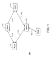
- Fig. 1 shows a block diagram of an optical communication system 100, in which the present invention can be practiced.
- System 100 has a network of nodes 102 coupled by bi-directional links 104 , where each of the nodes is adapted to process optical signals carried via the links.
- Signal processing at each node 102 includes, but is not limited to, routing optical signals between adjacent nodes, extracting (i.e., dropping) from the network traffic optical signals designated for local receivers, and inserting (i.e., adding) into the network traffic optical signals generated by local transmitters.
- Each link 104 may include one or more optical fibers, optical amplifiers (not shown), signal regenerators (not shown), and other customary components.
- Fig. 2 shows an optical add/drop multiplexer (OADM) 200 that can be used in any node 102 of system 100.
- OADM 200 has at least four ports including a main input port 202, a main output port 204, a drop port 206, and an add port 208.
- DWDM signals applied to main input port 202 are directed to either drop port 206 , e.g., for distribution to local receivers, or main output port 204, e.g., for further transmission over the network of system 100.
- the dropped signals are typically blocked from reaching main output port 204 .
- Some or all of the previously unused DWDM channels and/or DWDM channels corresponding to the dropped signals may then be used to transmit optical signals applied to add port 208 , e.g., from local transmitters. These optical signals are multiplexed with the optical signals received at main input port 202 that are not dropped at drop port 206, and the multiplexed signal is output at main output port 204.
- Fig. 3 shows a block diagram of an OADM 300 that can be used to implement OADM 200 according to one embodiment of the invention.
- OADM 300 is a six-port device having a main input port 302 , a main output port 304 , two drop ports 306a-b , and two add ports 308a-b .
- OADM 300 operates by directing DWDM signals applied to main input port 302 to either drop ports 306a-b , e.g., for distribution to local receivers, or main output port 304 , e.g., for further transmission over the network.
- the signals dropped at drop ports 306a-b are blocked from reaching main output port 304.
- Some or all of the previously unused DWDM channels and/or DWDM channels corresponding to the dropped signals may then be used to transmit optical signals applied to add ports 308a-b , e.g., from local transmitters. These optical signals are multiplexed with the optical signals received at main input port 302 that are not dropped at drop ports 306a-b , and the multiplexed signal is output at main output port 304.
- This functionality is realized in OADM 300 using a de-multiplexer (DMUX) 312, a multiplexer (MUX) 332 , two wavelength blockers 316a-b, two splitters 314a-b, and two combiners 334a-b, each of which is described in more detail below.
- DMUX de-multiplexer
- MUX multiplexer
- DMUX 312 is a three-port device having an input port labeled I, which is coupled to main input port 302, and two output ports labeled II and III. DMUX 312 is adapted to direct the optical signals applied to port I to one of its two output ports based on wavelength or DWDM channel number. More specifically, in one embodiment, DMUX 312 directs optical signals corresponding to a first group of DWDM channels to output port II, while directing optical signals corresponding to a second group of DWDM channels to output port III.
- MUX 332 is a three-port device having two input ports labeled II and III and an output port labeled I, which output port is coupled to main output port 304. MUX 332 is adapted to essentially perform a reverse function of that performed by DMUX 312. More specifically, MUX 332 multiplexes the optical signals applied to its input ports and directs the multiplexed signal to the output port.
- each of DMUX 312 and MUX 332 is implemented using a substantially identical bi-directional optical element. More specifically, this optical element is designed to route (i) optical signals corresponding to the first group of DWDM channels between ports I and II and (ii) optical signals corresponding to the second group of DWDM channels between ports I and III.
- this optical element is designed to route (i) optical signals corresponding to the first group of DWDM channels between ports I and II and (ii) optical signals corresponding to the second group of DWDM channels between ports I and III.
- DMUX 312 an input signal is applied to port I, and two corresponding output signals emerge at ports II and III.
- MUX 332 two input signals are applied to ports II and III, and a corresponding output signal emerges at port I.
- Each of wavelength blockers 316a-b is a configurable device, which transmits optical signals intended for main output port 304 and blocks optical signals intended for the corresponding drop port 306. As such, wavelength blockers 316a-b are adapted to handle optical signals corresponding to the first and second groups of DWDM channels, respectively. Based on appropriate control signals (not shown), each of wavelength blockers 316a-b can at different times block/transmit different sub-groups belonging to the corresponding group of DWDM channels.
- Each of splitters 314a-b is a passive three-port device adapted to split the signal received from DMUX 312 between the corresponding drop port 306 and wavelength blocker 316 .
- each of combiners 334a-b is a passive three-port device adapted to combine the signals received from the corresponding add port 308 and wavelength blocker 316 and direct the combined signal to MUX 332 .
- each of splitters 314a-b and combiners 334a-b is implemented using a substantially identical bi-directional optical element that, depending on the light-propagation direction, can operate as either a power splitter or power combiner.
- OADM 300 can route an optical signal applied to main input port 302 , for example, as follows. Suppose that this optical signal corresponds to the first group of DWDM channels. Then, DMUX 312 directs the signal to its output port II. Power splitter 314a then produces two signal copies and directs the first copy to drop port 306a and the second copy to wavelength blocker 316a . If the optical signal is intended to be dropped at drop port 306a , then wavelength blocker 316a is configured to block the second signal copy from propagating beyond the wavelength blocker. At the same time, a local receiver (not shown) coupled to drop port 306a receives the first signal copy, thereby accomplishing a drop function.
- a local transmitter (not shown) can now apply a different optical signal corresponding to the same DWDM channel to add port 308a without causing signal interference.
- Power combiner 334a then combines that signal with the signals transmitted by wavelength blocker 316a and directs the combined signal to input port II of MUX 332, which routes it to main output port 304, thereby accomplishing an add function.
- wavelength blocker 316a is configured to pass the second signal copy produced by power splitter 314a .
- a local receiver coupled to drop port 306a is configured to ignore the first signal copy. Since, in this situation, the corresponding DWDM channel is not vacant beyond wavelength blocker 316a, a local transmitter does not apply a different optical signal corresponding to the same DWDM channel to add port 308a to avoid signal interference.
- an optical signal corresponding to the second group of DWDM channels is processed in OADM 300 in a similar fashion, but using a different OADM branch, i.e., that including output port III of DMUX 312, the corresponding power splitter 314b , drop port 306b, wavelength blocker 316b , the corresponding power combiner 334b , add port 308b, and input port III of MUX 332.
- Fig. 4 shows a block diagram of a wavelength blocker 416 that can be used as either wavelength blocker 316 of Fig. 3 according to one embodiment of the invention.
- Wavelength blocker 416 has a circulator 410 , which directs a DWDM signal applied to the wavelength blocker, e.g., by power splitter 314 (Fig. 3), to a grating 420 .
- Grating 420 then disperses the signal in wavelength and directs it to an on/off switch 430 .
- the plurality of arrows between grating 420 and switch 430 represents light corresponding to different DWDM channels.
- Switch 430 has an array of rotatable MEMS mirrors, one mirror per DWDM channel.
- the corresponding mirror in switch 430 When an optical signal corresponding to a particular DWDM channel needs to pass through wavelength blocker 416 , the corresponding mirror in switch 430 is rotated to reflect the signal back to grating 420 , where it is recombined with other reflected signals and directed back to circulator 410 , which outputs it from the wavelength blocker, e.g., toward power combiner 334 (Fig. 3).
- the corresponding mirror in switch 430 is rotated to reflect the signal toward a signal dump 440 as shown by the dashed lines in Fig. 4, where the signal is absorbed.
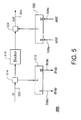
- Fig. 5 shows a block diagram of an OADM 500 that can be used to implement OADM 200 (Fig. 2) according to another embodiment of the invention. Similar to OADM 300 (Fig. 3), OADM 500 has a main input port 502 , a main output port 504 , two drop ports 506a-b , and two add ports 508a-b . OADM 500 operates similar to OADM 300 (Fig. 3) by directing optical signals applied to main input port 502 to either drop ports 506a-b or main output port 504.
- Some or all of the DWDM channels corresponding to the dropped signals and/or any unoccupied channels may be reused to transmit optical signals applied to add ports 508a-b , which are multiplexed with the optical signals received at main input port 502 that are not dropped at drop ports 506a-b .
- the multiplexed signal is then output at main output port 504 .
- OADM 500 has a DMUX 312 and a MUX 332 .
- OADM 500 also employs a power splitter 514 and a power combiner 534 that are similar to power splitter 314 and a power combiner 334 , respectively, of OADM 300 .
- a wavelength blocker 516 employed in OADM 500 is somewhat different from either one of wavelength blockers 316a-b of OADM 300 . More specifically, each of wavelength blockers 316a-b is adapted to process optical signals corresponding to only one group of DWDM channels. For example, wavelength blockers 316a and 316b process optical signals corresponding to the first and second groups of DWDM channels, respectively. In contrast, wavelength blocker 516 is adapted to process optical signals corresponding to both groups of DWDM channels.
- OADM 500 can route an optical signal applied to main input port 502 , for example, as follows.
- Power splitter 514 produces two signal copies and directs the first copy to DMUX 312 and the second copy to wavelength blocker 516 . If the optical signal is intended to be dropped at one of drop ports 506a-b , then wavelength blocker 516 is configured to block the second signal copy from propagating beyond the wavelength blocker.
- DMUX 312 directs the first signal copy to the corresponding one of drop ports 506a-b depending on whether the optical signal is in the first or second group of channels, and a local receiver (not shown) coupled to that drop port receives that signal copy, thereby accomplishing a drop function.
- a local transmitter (not shown) can now apply a different optical signal corresponding to the same DWDM channel to the appropriate one of add ports 508a-b without causing signal interference.
- MUX 332 then directs that signal to power combiner 534 , where the signals output by the MUX and the signals transmitted by wavelength blocker 516 are combined and directed to main output port 504 , thereby accomplishing an add function.
- wavelength blocker 516 is configured to pass the second signal copy produced by power splitter 514 .
- the local receiver coupled to the corresponding one of drop ports 506a-b is configured to ignore the first signal copy. Since, in this situation, the corresponding DWDM channel is not vacant beyond wavelength blocker 516 , a local transmitter does not apply a different optical signal corresponding to the same DWDM channel to the corresponding one of add ports 508a-b to avoid signal interference at power combiner 534 .
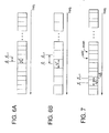
- Figs. 6A-B graphically show two representative DWDM channel configurations that can be used in certain embodiments of OADMs 200, 300, and 500. More specifically, in Figs. 6A-B, each DWDM channel is represented by a box having a base (e.g., center) frequency f i and a width ⁇ f (Fig. 6A) or ⁇ f' (Fig. 6B) corresponding to the bandwidth allocated to that channel, where i is the DWDM channel number.
- Each of the configurations shown in Figs. 6A-B utilizes an ITU (International Telecommunication Union) frequency grid, which provides that the base frequencies of two adjacent DWDM channels be separated by a frequency interval of mx 50 GHz, where m is a positive integer.
- ITU International Telecommunication Union
- each of the shown channel configurations allocates equal bandwidth to each DWDM channel.
- a typical prior-art communication system has all DWDM channels with the same uniform bandwidth, e.g., channels with a 50-GHz bandwidth only or, alternatively, channels with a 100-GHz bandwidth only.
- Each of the 100-GHz channels of Fig. 6B has a sufficient bandwidth for the transmission of either 10- or 40-Gb/s signals, while each of the 50-GHz channels of Fig. 6A has a sufficient bandwidth for the transmission of 10-Gb/s signals, but not for the transmission of conventional 40-Gb/s signals. More specifically, if used for the transmission of 40-Gb/s signals, the 50-GHz channels of Fig. 6A would, due to their limited bandwidth, cause signal distortions that would render the transmitted signals substantially un-decodable at the receiver. On the other hand, the use of the 100-GHz channels of Fig. 6B for the transmission of 10-Gb/s signals would cause the available spectral resources to be utilized relatively inefficiently.
- Fig. 7 graphically shows a DWDM channel configuration that can be used in OADMs 200 , 300 , and 500 according to one embodiment of the invention.
- Fig. 7 has two sets of channels, with the channels in one set having a bandwidth of ⁇ f 1 and the channels in the other set having a bandwidth of ⁇ f 2 , where ⁇ f 1 + ⁇ f 2 ⁇ 100 GHz .
- Channels in the two sets are interleaved as shown in Fig. 7 such that each odd channel has a bandwidth of ⁇ f 1 and each even channel has a bandwidth of ⁇ f 2 .
- ⁇ f 1 ⁇ 2 ⁇ f 2 ⁇ 66.7 GHz .
- the channel configuration illustrated in Fig. 7 is referred to as an example of an alternated channel configuration.
- the alternated channel configuration of Fig. 7 has the same maximum supportable channel density, about 1 channel per 50 GHz, as the configuration of Fig. 6A. However, unlike the latter, the alternated channel configuration is suitable for the transmission of both 10- and 40-Gb/s signals.
- each of the odd channels of Fig. 7 can be used for the transmission of 40-Gb/s signals, while each of the even channels can be used for the transmission of 10-Gb/s signals.
- the extra bandwidth allocated to each odd channel compared to that in Fig. 6A is such that the corresponding signal distortions induced due to the bandwidth limitations become acceptable for successfully decoding 40-Gb/s signals at the receiver. Of course, the extra bandwidth is added to odd channels at the expense of even channels.
- a populated 40-Gb/s channel may not be adjacent to a populated 10-Gb/s channel in communication systems configured for long-distance transmissions, e.g., greater than about 800 km.
- the relative bandwidths of the odd and even channels in the alternated channel configuration are selected such that the penalty on the transmission of 10-Gb/s signals and the improvement in the transmission of 40-Gb/s signals with respect to the configuration of Fig. 6A are balanced to achieve an optimum overall transmission quality.
- the alternated channel configuration has certain advantages over the configuration of Fig. 6B because it uses the available spectral resources more efficiently and has a higher spectral density of channels.
- OADM 300 (Fig. 3) can be adapted to process optical signals corresponding to the alternated channel configuration of Fig. 7, for example, as follows.
- the first group of channels, which is routed through the OADM branch coupled between port II of DMUX 312 and port II of MUX 332 includes the even channels of Fig. 7.
- the second group of channels, which is routed through the OADM branch coupled between port III of DMUX 312 and port III of MUX 332 includes the odd channels of Fig. 7.
- OADM 500 (Fig. 5) can be adapted to process optical signals corresponding to the alternated channel configuration of Fig. 7, for example, as follows.
- the first group of channels, which is routed between main input port 502 , drop port 506a , add port 508a , and main output port 504 includes the even channels of Fig. 7; and the second group of channels, which is routed between main input port 502 , drop port 506b , add port 508b , and main output port 504 includes the odd channels of Fig. 7.
- wavelength blocker 516 needs to be adapted to handle channels of both bandwidths, as discussed in more detail below.
- Fig. 8 graphically illustrates properties of a bi-directional optical interleaver 800 that can be used to implement DMUX 312 and/or MUX 332 in each of OADMs 300 and 500 according to one embodiment of the invention. More specifically, the top and bottom panels in Fig. 8 graphically show the group-delay (GD) and attenuation profiles, respectively, of optical interleaver 800 .
- curve 810 in Fig. 8 corresponds to light attenuation (i) in DMUX 312 between ports I and III and, also, (ii) in MUX 332 between ports III and I.
- curve 810 corresponds to light attenuation (i) in DMUX 312 between ports I and II and, also, (ii) in MUX 332 between ports II and I.
- curve 810 has a plurality of transmission bands each having (i) a base frequency on a 100-GHz grid with grid lines located at 0, 100, 200 GHz, etc. and (ii) a 3-dB bandwidth of about 65 GHz.
- Transmission ripples located at about 50, 150, 250 GHz, etc. between the transmission bands are primarily due to the interference effects in optical interleaver 800 . These transmission ripples are neither substantially beneficial nor substantially detrimental to the operation of the interleaver in an OADM of the invention.
- curve 820 has a plurality of transmission bands each having (i) a base frequency on a 100-GHz grid with grid lines located at 50, 150, 250 GHz, etc. and (ii) a 3-dB bandwidth of about 35 GHz.
- optical interleaver 800 is fabricated using the planar waveguide technology, the application of which to the fabrication of optical interleavers, multiplexers, and de-multiplexers is known in the art and described, for example, in U.S. Patent Nos. 6,591,038 and 6,560,380, the teachings of both of which are incorporated herein by reference.
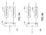
- Figs. 9A-B show block diagrams of a DMUX 912 and a MUX 932 that can be used as DMUX 312 and MUX 332 , respectively, according to one embodiment of the invention.
- curve 830 indicates that the amplitude of peak-to-peak GD ripples in optical interleaver 800 is on the order of 20 ps, i.e., about 80% of the duration of a 40-Gb/s signaling interval.
- Each of DMUX 912 and MUX 932 addresses this problem by having a pair of dispersion compensators 930a-b coupled to interleaver 800 of Fig. 8.
- Each of dispersion compensators 930a-b serves to reduce the amplitude of peak-to-peak GD ripples down to a desired level.
- dispersion compensators 930a-b are configured to compensate for the group delay already induced in optical interleaver 800 , which is located upstream from the compensators.
- dispersion compensators 930a-b are configured to pre-compensate for the group delay that will be induced in optical interleaver 800 , which is located downstream from the compensator.
- each of dispersion compensators 930a-b is a compensator disclosed in commonly owned U.S. Patent No. 6,631,246, the teachings of which are incorporated herein by reference.
- wavelength blocker 416 can be designed to implement wavelength blocker 316 (Fig. 3) for the alternated channel configuration in a relatively straightforward fashion. Namely, when wavelength blocker 416 implements wavelength blocker 316a, the array of rotatable MEMS mirrors in switch 430 has gaps between adjacent mirrors, with each gap centered at about the wavelength of the corresponding even channel. Similarly, when wavelength blocker 416 implements wavelength blocker 316b, the array of rotatable MEMS mirrors in switch 430 has gaps between adjacent mirrors with each gap centered at about the wavelength of the corresponding odd channel.
- wavelength blocker 416 can be designed to implement wavelength blocker 516 (Fig. 5) as follows.
- the array of rotatable MEMS mirrors in switch 430 has mirrors of two different widths. More specifically, the relative mirror widths in switch 430 correspond to the relative DWDM channel bandwidths. For example, a relatively wide mirror corresponding to an odd DWDM channel is followed by a relatively narrow mirror corresponding to an even DWDM channel, which is followed by a next relatively wide mirror corresponding to an odd DWDM channel, etc.
- Communication system 100 (Fig. 1) employing the alternated channel configuration can increase its capacity by, e.g., replacing the transmission of 10-Gb/s signals in some odd bands of Fig. 7 with the transmission of 40-Gb/s signals, while leaving the transmission of 10-Gb/s signals in some even bands of Fig. 7 substantially undisrupted.
- a corresponding system upgrade includes upgrading only the system components coupled to drop ports 306b and 506b and add ports 308b and 508b of OADMs 300 and 500, respectively.
- this upgrade achieves a desired purpose of adding a 40-Gb/s service while minimizing disruptions to the 10-Gb/s service already in place.
- Other beneficial options might be available to the operator of communication system 100 if, at the time of the upgrade, the system did not operate at full capacity. For example, if only odd channels were occupied with the transmission of 10-Gb/s signals while the even channels were vacant, the 10-Gb/s signals can be rolled over into the even channels. Then, the freed odd channels can be populated with new 40-Gb/s services.
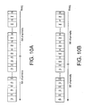
- FIGs. 10A-B graphically illustrate two possible DWDM channel-population schemes in communication system 100 (Fig. 1), which employs an alternated channel configuration having 64 odd channels and 64 even channels, for the total of 128 channels.
- communication system 100 employing, in each node 102 , an OADM analogous to OADM 300 (Fig. 3) can increase its capacity by (1) starting with the transmission of 10-Gb/s signals, (2) at some point, adding the transmission of 40-Gb/s signals, and (3) then increasing the number of 10-Gb/s signals.
- each OADM uses only one branch (e.g., including ports analogous to drop port 306a and add port 308a ) while the other branch (e.g., including ports analogous to drop port 306b and add port 308b ) remains substantially unutilized.
- an operator of system 100 may increase the system capacity by populating 32 odd DWDM channels in the second 64 channels with the transmission of 40-Gb/s signals.
- these additionally populated channels are labeled with the letter " ⁇ ". With the ⁇ - and ⁇ -channels populated, each OADM uses both of its optical branches.
- the operator of system 100 may increase the system capacity even further by populating the 32 remaining odd DWDM channels in the first 64 channels with the transmission of 10-Gb/s signals.
- the channels populated during this upgrade are labeled with the letter " ⁇ ". With the ⁇ -channels populated, each OADM reaches a capacity of 64 10-Gb/s channels and 32 40-Gb/s channels, for a total of 96 populated channels.
- the operator of system 100 may increase the system capacity still further by populating the remaining unpopulated DWDM channels with the transmission of 10-Gb/s signals.
- these additionally populated channels are labeled with the letter " ⁇ ".
- DPSK differential phase-shift keying
- the ⁇ -channels can be populated with 40-Gb/s signals when bandwidth-efficient modulation formats, such as optical duobinary or differential-quadrature phase-shift keying (DQPSK) are used.
- bandwidth-efficient modulation formats such as optical duobinary or differential-quadrature phase-shift keying (DQPSK) are used.
- DQPSK differential-quadrature phase-shift keying
- other bandwidth-efficient signals e.g. 80-Gb/s DQPSK signals
- 80-Gb/s DQPSK signals can also be used to populate various channels of Fig. 10A.
- FIG. 10B An upgrade scheme similar to that just described in the context of Fig. 10A is shown in Fig. 10B. Accordingly, the ⁇ -, ⁇ -, ⁇ -, and ⁇ -channels shown in Fig. 10B correspond to the upgrade stages analogous to those which populated the similarly labeled channels in Fig. 10A.
- an important difference between the schemes of Figs. 10A and 10B is in the distribution of channels with different data rates (and modulation formats), the number of populated channels of each type after each upgrade and, therefore, in the realized system capacity. This difference can readily be discerned in the table, which follows. Number of Populated Channels in the Course of System Upgrades Upgrade Stage Fig. 10A Fig.
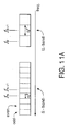
- Fig. 11A graphically shows a DWDM channel configuration that can be in OADMs 200, 300, and 500 according to one embodiment of the invention.
- Fig. 11A is analogous to Figs. 6 and 7 in the graphical depiction of DWDM channels. Similar to the alternated channel configuration of Fig. 7, the configuration of Fig. 11A has two sets of channels, wherein the channels in one set have a bandwidth of ⁇ f and the channels in the other set have a bandwidth of ⁇ f ' different from ⁇ f . However, channels in the two sets are not interleaved as in Fig. 7, but instead, are bundled into two separate spectral bands labeled as "S-band" and "L-band", respectively.
- the S- and L-bands correspond to different amplification bands of an erbium-doped fiber amplifier (EDFA).
- EDFA erbium-doped fiber amplifier
- the channel configuration illustrated in Fig. 11A is referred to as an example of a banded channel configuration. Note that a guard spectral band may need to be present between the S-band and L-band to avoid band-edge distortions.
- the banded channel configuration of Fig. 11A is suitable for the transmission of both 10- and 40-Gb/s signals.
- each of the channels in the L-band can be used for the transmission 40-Gb/s signals
- each of the channels in the S-band can be used for the transmission 10-Gb/s signals.
- the banded channel configuration enables a simultaneous existence in the system of 10-Gb/s and 40-Gb/s channels with good individual performances.
- the bandwidth allocations for the 10-Gb/s and 40-Gb/s channels can be flexible or adjustable, as shown in more detail below.
- Fig. 11B illustrates properties of a DMUX 1112 that can be used as DMUX 312 according to one embodiment of the invention.
- DMUX 1112 has three ports (labeled I, II, and III), which are analogous to the similarly labeled ports of DMUX 312.
- Fig. 11B which is analogous to Fig. 11A in the graphical depiction of DWDM channels, graphically illustrates a channel-routing scheme implemented in DMUX 1112.
- optical signals corresponding to odd DWDM channels of the S-band are routed from port I to port II
- optical signals corresponding to even DWDM channels of the S-band are routed from port I to port III
- optical signals corresponding to all DWDM channels of the L-band are routed from port I to port III.
- Fig. 11B also illustrates properties of a MUX 1132 that can be used as MUX 332 according to one embodiment of the present invention.
- MUX 1132 has three ports (labeled I, II, and III), which are analogous to the similarly labeled ports of MUX 332 .
- the channel-routing scheme implemented in MUX 1132 is as follows. Optical signals corresponding to odd DWDM channels of the S-band are routed from port II to port I, optical signals corresponding to even DWDM channels of the S-band are routed from port III to port I, and optical signals corresponding to all DWDM channels of the L-band are routed from port III to port I.
- An OADM analogous to OADM 300 (Fig. 3) and having DMUX 1112 and MUX 1132 of Fig. 11B in place of DMUX 312 and MUX 332, respectively, is adapted to process optical signals corresponding to the banded channel configuration of Fig. 11A as follows.
- the first group of channels, which is routed through the OADM branch coupled between port II of DMUX 1112 and port II of MUX 1132, includes odd DWDM channels of the S-band of Fig. 11A.
- the second group of channels, which is routed through the OADM branch coupled between port III of DMUX 1112 and port III of MUX 1132, includes even DWDM channels of the S-band and all DWDM channels of the L-band of Fig.
- an OADM analogous to OADM 500 (Fig. 5) and having DMUX 1112 and MUX 1132 of Fig. 11B in place of DMUX 312 and MUX 332, respectively, is adapted to process optical signals corresponding to the banded channel configuration of Fig. 11 A as follows.
- the first group of channels, which is routed between main input port 502 , drop port 506a , add port 508a , and main output port 504 includes odd DWDM channels of the S-band of Fig. 11A.
- the second group of channels which is routed between main input port 502 , drop port 506b , add port 508b , and main output port 504 includes even DWDM channels of the S-band and all DWDM channels of the L-band of Fig. 11A.
- Fig. 12 shows a block diagram of a DMUX 1212 that can be used to implement DMUX 1112 illustrated in Fig. 11B according to one embodiment of the invention.
- DMUX 1212 routes optical signals as follows.
- An optical signal applied to port I is directed to a band splitter 1202 having a characteristic wavelength (or characteristic frequency f C ).
- Band splitter 1202 serves to separate light having wavelengths shorter and longer than the characteristic wavelength into two different beams and direct one beam toward a de-interleaver 1204 and the other beam toward a power combiner 1206 .
- Band splitter 1202 can, for example, be implemented using a glass plate oriented at 45 degrees with respect to the light propagation direction and having a dielectric coating, which transmits light with wavelengths longer than the characteristic wavelength and reflects light with wavelengths shorter than the characteristic wavelength.
- the characteristic wavelength is preferably such that the corresponding characteristic frequency is located between the S- and L-bands (see Figs. 11 A and 11B).
- band splitter 1202 is a tunable element, which allows one to change the characteristic wavelength/frequency.
- the tuning can, for example, be accomplished by changing the orientation angle of the glass plate or changing its temperature. This feature enables flexible and/or adjustable bandwidth allocation for the S- and L-bands, which enables selection of a desired relative quantity of 10- and 40-Gb/s channels in the system.
- De-interleaver 1204 is adapted to sort optical signals based on wavelength or DWDM channel number. For example, optical signals corresponding to odd DWDM channels of the S-band are directed toward port II while optical signals corresponding to even DWDM channels of the S-band are directed toward power combiner 1206 .
- De-interleavers similar to de-interleaver 1204 are well known in the art and are disclosed, for example, in U.S. Patent No. 6,560,380, the teachings of which are incorporated herein by reference.
- Power combiner 1206 is analogous to, e.g., power combiner 334 of Fig. 3. As such, it combines the signals received from band splitter 1202 and de-interleaver 1204 and directs the combined signal to port III.
- Fig. 13 shows a block diagram of a MUX 1332 that can be used to implement MUX 1132 illustrated in Fig. 11B according to one embodiment of the invention.
- MUX 1332 routes optical signals as follows.
- An optical signal applied to port III is directed to a band splitter 1302, which serves to separate light corresponding to the S- and L-bands into two different beams. More specifically, optical signals corresponding to the S-band are directed toward an interleaver 1304 while optical signals corresponding to the L-band are directed toward a band combiner 1306 .
- band splitter 1302 is similar to band splitter 1202 of Fig. 12.
- Interleaver 1304 is adapted to essentially perform a reverse function of that performed by de-interleaver 1204 .
- interleaver 1304 multiplexes the optical signals received from port II and band splitter 1302 and directs the multiplexed signal to a power combiner 1306 .
- power combiner 1306 is analogous to, e.g., power combiner 334 of Fig. 3. As such, it combines the signals received from band splitter 1302 and interleaver 1304 and directs the combined signal to port I.
- each of DMUX 1212 and MUX 1332 can be implemented using different instances of the same bi-directional optical assembly.
- an optical assembly having a first bi-directional optical element analogous to band splitter 1202 , a second bi-directional optical element analogous to band splitter 1202 , and a bi-directional optical interleaver in place of, e.g., band splitter 1202 , power combiner 1206 , and de-interleaver 1204 (Fig. 2), respectively, can serve, depending on the light propagation direction, as either DMUX 1212 or MUX 1332 .
- wavelength blocker 416 can be designed to implement wavelength blocker 316a (Fig. 3) for the banded channel configuration in a relatively straightforward fashion. Namely, when wavelength blocker 416 implements wavelength blocker 316a, the array of rotatable MEMS mirrors in switch 430 has mirrors corresponding to odd DWDM channels of the S-band of Fig. 11A. This wavelength blocker has gaps between adjacent mirrors, each of which gaps is centered at about the wavelength of the corresponding even channel of the S-band. Wavelength blocker 416 can be designed to implement wavelength blocker 316b , for example, as follows.
- the array of rotatable MEMS mirrors in switch 430 has two groups of mirrors. More specifically, the first group has mirrors corresponding to even DWDM channels of the S-band, and the second group has mirrors corresponding to DWDM channels of the L-band. As such, mirrors in the first group are narrower than mirrors in the second group. In addition, mirrors in the first group have gaps between adjacent mirrors, each of which gaps is centered at about the wavelength of the corresponding odd channel of the S-band.
- wavelength blocker 416 can be designed to implement wavelength blocker 516 (Fig. 5) for the banded channel configuration as follows.
- the array of rotatable MEMS mirrors in switch 430 has two groups of mirrors. More specifically, the first group has mirrors corresponding to (both odd and even) DWDM channels of the S-band, and the second group has mirrors corresponding to DWDM channels of the L-band. As such, mirrors in the first group are narrower than mirrors in the second group. In addition, mirrors in the first and second groups have relatively narrow gaps between adjacent mirrors to accommodate all channels of the S- and L-bands, respectively.
- Figs. 14A-B graphically illustrate two DWDM channel-population schemes in communication system 100 (Fig. 1), which employs the banded channel configuration. More specifically, Fig. 14A shows a situation in which (i) the total bandwidth allocated to the S-band is substantially equal to the total bandwidth allocated to the L-band and (ii) the S- and L-bands accommodate 64 and 32 DWDM channels, respectively. Similarly, Fig. 14B shows a situation in which (i) the total bandwidth allocated to the S-band is substantially three times larger than the total bandwidth allocated to the L-band and (ii) the S- and L-bands accommodate 96 and 16 DWDM channels, respectively.
- communication system 100 (Fig. 1) employing, in each node 102 , an OADM analogous to OADM 300 (Fig. 3), which OADM has DMUX 1212 (Fig. 12) and MUX 1332 (Fig. 13), can increase its capacity by (1) increasing the number of transmitted 10-Gb/s signals and (2) at some point, adding the transmission of 40-Gb/s signals and then increasing their number as well.
- OADM analogous to OADM 300
- OADM OADM has DMUX 1212 (Fig. 12) and MUX 1332 (Fig. 13)
- each OADM uses only one branch (e.g., including ports analogous to drop port 306a and add port 308a ) while the other branch (e.g., including ports analogous to drop port 306b and add port 308b) remains substantially unutilized (also see Figs. 11A-11B).
- an operator of system 100 may increase the system capacity by populating 16 additional DWDM channels in the S-band for the transmission of additional 10-Gb/s signals.
- these additionally populated channels are labeled with the letter " ⁇ ".
- ⁇ a preferred spacing between the base frequencies of adjacent ⁇ - and ⁇ -channels.
- ⁇ -channels in the S-band are employed for the transmission of 10-Gb/s signals
- ⁇ -channels in the L-band can be employed for the transmission of 40-Gb/s signals.
- this upgrade can achieve a desired purpose of adding a 40-Gb/s service without disrupting the 10-Gb/s service already in place.
- the current traffic volume of the 10-Gb/s service is increased.
- the operator of system 100 may increase the system capacity even further by populating the 16 remaining DWDM channels in the S-band and the 16 remaining DWDM channels in the L-band.
- the channels populated during this upgrade are labeled with the letter " ⁇ ". With the ⁇ -channels populated, each OADM reaches its full capacity of 64 10-Gb/s channels and 32 40-Gb/s channels, for a total of 96 channels.
- FIG. 14A An upgrade scheme similar to that just described in the context of Fig. 14A may also be implemented for the S- and L-bands of Fig. 14B. Accordingly, the ⁇ -, ⁇ -, ⁇ -, and ⁇ -channels shown in Fig. 14B correspond to the upgrade stages analogous to those which populated the similarly labeled channels in Fig. 14A.
- an important difference between the schemes of Figs. 14A and 14B is in the number of populated channels of each type after each upgrade and, therefore, in the realized system capacity. This difference can readily be discerned in the table, which follows. Number of Populated Channels in the Course of System Upgrades Upgrade Stage Fig. 14A Fig.
- a hybrid DWDM channel configuration may be realized by having channels similar to those of the alternated channel configuration of Fig. 7 in the S-band of the banded channel configuration of Fig. 11A.
- the channels of the first and second sets are interleaved with each other and occupy the S-band, and the channels of the third set occupy the L-band.
- wavelength blocker 416 (Fig. 4)
- switch 430 and signal dump 440 can be replaced with an array of fixed mirrors and a segmented LC (liquid-crystal) mask positioned between grating 420 and that array of fixed mirrors.
- Each segment of the LC mask can then be turned on or off to block or pass, respectively, light traveling between the grating and the fixed mirror corresponding to the segment.
- Different DWDM channel-population schemes can be implemented without departing from the principles of the invention.
- multiplexers and de-multiplexers of the invention have been described in the context of their use in OADMs, one skilled in the art will understand that these multiplexers and de-multiplexers can also be used in other optical routing devices.
- OADMs of the invention can be designed to process more than two sets of channels. Consequently, each of such OADMs has a corresponding number of branches, each adapted to process DWDM channels of the corresponding set of channels.
Landscapes
- Engineering & Computer Science (AREA)
- Computer Networks & Wireless Communication (AREA)
- Signal Processing (AREA)
- Optical Communication System (AREA)
- Time-Division Multiplex Systems (AREA)
Abstract
Description
| Number of Populated Channels in the Course of System Upgrades | ||||||
| Upgrade Stage | Fig. 10A | Fig. 10B | ||||
| Even | Odd | Total | Even | Odd | Total | |
| α | 32 | - | 32 | 48 | - | 48 |
| α+ | 32 | 32 | 64 | 48 | 16 | 64 |
| α+β+γ | 32 | 64 | 96 | 48 | 64 | 112 |
| α+β+γ+ | 64 | 64 | 128 | 64 | 64 | 128 |
| Number of Populated Channels in the Course of System Upgrades | ||||||
| Upgrade Stage | Fig. 14A | Fig. 14B | ||||
| S-band | L-band | Total | S-band | L-band | Total | |
| α | 16 | - | 16 | 24 | - | 24 |
| α+β | 32 | - | 32 | 48 | - | 48 |
| α+β+γ | 48 | 16 | 64 | 72 | 8 | 80 |
| α+β+γ+ | 64 | 32 | 96 | 96 | 16 | 112 |
Claims (10)
- An optical apparatus, comprising a plurality of ports having first, second, and third ports, which apparatus is adapted to route optical signals between different ports based on wavelength, wherein:
the optical signals correspond to two or more sets of channels, each set having one or more channels with a corresponding bandwidth value;
at least two different sets of channels have different bandwidth values; and the optical apparatus comprises a routing device adapted to:route optical signals corresponding to a first group of channels between the first port and the second port; androute optical signals corresponding to a second group of channels between the first port and the third port. - The invention of claim 1, wherein:the two or more sets of channels include first and second sets of channels;each channel in the first set has a first bandwidth value;each channel in the second set has a second bandwidth value;the channels of the first set occupy a first spectral band;the channels of the second set occupy a second spectral band; andthe first and second spectral bands are continuous bands distinct from each other.
- The invention of claim 1, wherein:the two or more sets of channels include first, second, and third sets of channels;each channel in the first set has a first bandwidth value;each channel in the second set has a second bandwidth value;each channel in the third set has a third bandwidth value;the channels of the first and second sets occupy a first spectral band;the channels of the third set occupy a second spectral band;the first and second spectral bands are continuous bands distinct from each other; andthe channels of the first set are interleaved with the channels of the second set.
- The invention of claim 1, wherein:
the first group of channels is a first subset of the first set of channels;
the second group of channels includes the second set of channels and a second subset of the first set of channels;
channels from the first set occupy a first spectral band, wherein channels from the first subset are interleaved with channels from the second subset; and
channels from the second set occupy a second spectral band distinct from the first spectral band. - The invention of claim 4, wherein the routing device comprises:a band splitter coupled to the first port and adapted to divide an optical beam applied to the first port into first and second beams, wherein the first beam corresponds to the first spectral band and the second beam corresponds to the second spectral band;a de-interleaver adapted to receive the first optical beam and divide said beam into first and second sub-beams, wherein (i) the first sub-beam corresponds to the first subset and is directed to the second port and (ii) the second sub-beam corresponds to the second subset and is directed to a combiner; andthe combiner adapted to combine the second sub-beam with the second beam and direct the combined beam to the third port.
- The invention of claim 4, wherein the routing device comprises:a band splitter coupled to the third port and adapted to divide an optical beam applied to the third port into first and second sub-beams, wherein the first sub-beam corresponds to the first spectral band and the second sub-beam corresponds to the second spectral band;an interleaver adapted to receive the first sub-beam, combine said sub-beam with an optical beam applied to the second port, and direct the combined beam to a combiner;the combiner adapted to further combine the combined beam with the second beam and direct the resulting beam to the first port;the optical beam applied to the second port has optical signals corresponding to the first group of channels; andthe optical beam applied to the third port has optical signals corresponding to the second group of channels.
- The invention of claim 1, wherein the optical apparatus comprises an optical add/drop multiplexer (OADM) and the routing device is a part of said OADM, wherein the OADM comprises first and second optical branches, both coupled between a DMUX and a MUX, wherein:the DMUX is coupled to a main input port and adapted to route (i) optical signals corresponding to the first group of channels via the first optical branch and (ii) optical signals corresponding to the second group of channels via the second optical branch;the MUX is coupled to a main output port and adapted to route optical signals received via the first and second optical branches to said main output port; andeach optical branch includes:a wavelength blocker adapted to block one or more selected channels belonging to a corresponding group of channels;a splitter coupled between the DMUX and the wavelength blocker, wherein the splitter is adapted to (i) split a signal received from the DMUX into first and second split signals and (ii) direct the first slit signal to the wavelength blocker and the second split signal to a drop port; anda combiner coupled between the wavelength blocker and the MUX, wherein the combiner is adapted to (i) combine signals received from the wavelength blocker and an add port and (ii) direct the combined signal to the MUX.
- The invention of claim 1, wherein:
the optical apparatus comprises an optical add/drop multiplexer (OADM) and the routing device is a part of said OADM; and
the OADM comprises:a wavelength blocker coupled between a main input port and a main output port and adapted to block one or more selected channels;a signal splitter coupled between the main input port and the wavelength blocker and adapted to direct signals received from the main input port to the wavelength blocker and a DMUX;the DMUX coupled the signal splitter and adapted to direct (i) optical signals corresponding to the first group of channels to a first drop port and (ii) optical signals corresponding to the second group of channels to a second drop port;a signal combiner coupled between the wavelength blocker and the main output port and adapted to combine signals received from the wavelength blocker and a MUX and direct the combine signal to the main output port; andthe MUX adapted to direct optical signals applied to first and second add ports to the signal combiner. - A method of transmitting optical signals, comprising:routing optical signals corresponding to a first group of channels between a first port and a second port of an optical routing device; androuting optical signals corresponding to a second group of channels between the first port and a third port of said optical routing device, wherein:
the optical signals correspond to two or more sets of channels, each set having one or more channels with a corresponding bandwidth value; and
at least two different sets of channels have different bandwidth values. - The invention of claim 9, wherein:
the two or more sets of channels include first and second sets of channels;
each channel in the first set has a first bandwidth value;
each channel in the second set has a second bandwidth value;
the channels of the first set occupy a first spectral band;
the channels of the second set occupy a second spectral band; and
the first and second spectral bands are continuous bands distinct from each other.
Applications Claiming Priority (2)
| Application Number | Priority Date | Filing Date | Title |
|---|---|---|---|
| US869663 | 1978-01-16 | ||
| US10/869,663 US7286763B2 (en) | 2004-06-16 | 2004-06-16 | Optical add/drop multiplexer having a banded channel configuration |
Publications (3)
| Publication Number | Publication Date |
|---|---|
| EP1608097A2 true EP1608097A2 (en) | 2005-12-21 |
| EP1608097A3 EP1608097A3 (en) | 2006-03-22 |
| EP1608097B1 EP1608097B1 (en) | 2014-12-17 |
Family
ID=34941565
Family Applications (1)
| Application Number | Title | Priority Date | Filing Date |
|---|---|---|---|
| EP05253423.7A Expired - Fee Related EP1608097B1 (en) | 2004-06-16 | 2005-06-03 | Optical add/drop multiplexer having a banded channel configuration |
Country Status (4)
| Country | Link |
|---|---|
| US (1) | US7286763B2 (en) |
| EP (1) | EP1608097B1 (en) |
| JP (1) | JP4571020B2 (en) |
| CN (1) | CN1713558B (en) |
Cited By (4)
| Publication number | Priority date | Publication date | Assignee | Title |
|---|---|---|---|---|
| WO2008067747A1 (en) | 2006-12-07 | 2008-06-12 | Huawei Technologies Co., Ltd. | Method and system for band blocking in an optical telecommunication network |
| CN100433834C (en) * | 2006-01-04 | 2008-11-12 | 天津大学 | Multi-point video transmitting system with single optical fiber |
| CN111487723A (en) * | 2014-03-07 | 2020-08-04 | 艾易珀尼斯公司 | Method and system for wavelength tunable optical components and subsystems |
| US11336386B2 (en) | 2017-09-28 | 2022-05-17 | Nec Corporation | Submarine branching apparatus, optical submarine cable system, and optical communication method |
Families Citing this family (23)
| Publication number | Priority date | Publication date | Assignee | Title |
|---|---|---|---|---|
| JP4530821B2 (en) * | 2004-08-16 | 2010-08-25 | 富士通株式会社 | Optical add / drop device |
| JP4445373B2 (en) * | 2004-10-29 | 2010-04-07 | 富士通株式会社 | Light switch |
| WO2008035753A1 (en) * | 2006-09-21 | 2008-03-27 | Nippon Telegraph And Telephone Corporation | Wavelength blocker |
| US20080131130A1 (en) * | 2006-12-05 | 2008-06-05 | Electronics And Telecommunications Research Institute | Optical network node device |
| US20080226227A1 (en) * | 2007-03-13 | 2008-09-18 | Tenvera, Inc. | Privacy in an Optical Fiber Link |
| US8965220B2 (en) * | 2007-05-30 | 2015-02-24 | Tellabs Operations, Inc. | Reconfigurable optical add/drop multiplexer and procedure for outputting optical signals from such multiplexer |
| TWI353741B (en) * | 2007-10-31 | 2011-12-01 | Ind Tech Res Inst | Prevention of collision for time division multiple |
| US8064768B2 (en) * | 2007-12-19 | 2011-11-22 | Nec Laboratories America, Inc. | Intra-channel equalizing optical interleaver |
| US7664348B2 (en) * | 2007-12-21 | 2010-02-16 | Teledyne Scientific & Imaging, Llc | Optical switch with reconfigurable broadcasting and combining capabilities |
| JP4937983B2 (en) * | 2008-10-16 | 2012-05-23 | 日本電信電話株式会社 | Optical transmission equipment |
| US8670664B2 (en) * | 2010-02-26 | 2014-03-11 | Fujitsu Limited | System and method for managing the selection of ghost channels for mitigating polarization hole burning |
| US8811822B2 (en) * | 2010-02-26 | 2014-08-19 | Fujitsu Limited | System and method for selection of ghost channels for mitigating polarization hole burning |
| US8542992B2 (en) | 2010-02-26 | 2013-09-24 | Fujitsu Limited | System and method for mitigating polarization hole burning |
| JP5614126B2 (en) | 2010-06-28 | 2014-10-29 | 富士通株式会社 | Transmission apparatus and transmission system |
| US20120183292A1 (en) * | 2011-01-14 | 2012-07-19 | Tellabs Operations, Inc. | Method and apparatus for trafficking wavelengths of different spacings within an optical node |
| US20140226939A1 (en) * | 2011-09-22 | 2014-08-14 | OFS Fitel ,LLC | Optical fiber distribution cables |
| JP5312553B2 (en) * | 2011-10-28 | 2013-10-09 | 日本電信電話株式会社 | Optical add / drop multiplexer |
| WO2013162433A1 (en) * | 2012-04-24 | 2013-10-31 | Telefonaktiebolaget L M Ericsson (Publ) | Method for split spectrum signalling in an optical network |
| JP5911104B2 (en) * | 2012-12-26 | 2016-04-27 | Necエンジニアリング株式会社 | Optical demultiplexing transmission apparatus, control method, and optical demultiplexing transmission control system |
| US9414134B2 (en) * | 2013-10-02 | 2016-08-09 | Nec Corporation | Secure wavelength selective switch-based reconfigurable branching unit for submarine network |
| US20150256908A1 (en) * | 2014-03-05 | 2015-09-10 | Oplink Communications, Inc. | N-degree cdc wsx roadm |
| JP2019015833A (en) * | 2017-07-06 | 2019-01-31 | 日本電信電話株式会社 | Wavelength selective switch module |
| US10680737B1 (en) * | 2019-04-09 | 2020-06-09 | Ciena Corporation | Bundling capacity changes in channel holder based optical links |
Family Cites Families (26)
| Publication number | Priority date | Publication date | Assignee | Title |
|---|---|---|---|---|
| SE514658C2 (en) | 1994-12-21 | 2001-03-26 | Ericsson Telefon Ab L M | Node Architecture for Application of Optical Optimization (OADM) |
| US5953141A (en) | 1996-10-03 | 1999-09-14 | International Business Machines Corporation | Dynamic optical add-drop multiplexers and wavelength-routing networks with improved survivability and minimized spectral filtering |
| US6404525B1 (en) * | 1997-07-31 | 2002-06-11 | Nec Corporation | Optical add-drop multiplexer |
| JP4011187B2 (en) | 1998-03-20 | 2007-11-21 | 富士通株式会社 | Optical multiplexer / demultiplexer |
| US6631246B2 (en) | 1999-06-14 | 2003-10-07 | Lucent Technologies Inc. | Wavelength division multiplexed optical communication system having tunable multi-channel dispersion compensating filters |
| WO2001018573A1 (en) | 1999-09-08 | 2001-03-15 | Corning Incorporated | Hybrid integrated optical add-drop multiplexer |
| EP1126650A3 (en) | 2000-02-18 | 2007-01-03 | Ericsson AB | Optical communication system |
| CA2337598A1 (en) * | 2000-03-31 | 2001-09-30 | Magaly Spector | Apparatus for demultiplexing/multiplexing optical signals modulated with different data rates in wdm systems |
| JP4647074B2 (en) * | 2000-10-04 | 2011-03-09 | 富士通株式会社 | WDM optical communication system |
| CN100407602C (en) * | 2001-01-05 | 2008-07-30 | 富士通株式会社 | A Control Scheme for Long Wavelength Channels in Wideband WDM Optical Fiber Transmission Systems |
| TW496975B (en) | 2001-03-02 | 2002-08-01 | Ind Tech Res Inst | Planar lightwave circuit interleaver |
| JP4588234B2 (en) * | 2001-03-15 | 2010-11-24 | 富士通株式会社 | Optical device and wavelength division multiplexing communication system using the same |
| US6591038B1 (en) | 2001-04-03 | 2003-07-08 | Jds Uniphase Corporation | Optical interleaver and demultiplexing apparatus for wavelength division multiplexed optical communications |
| US6597842B2 (en) | 2001-05-21 | 2003-07-22 | Copley Networks, Inc. | Optical interleaver with image transfer element |
| TW550409B (en) | 2001-06-07 | 2003-09-01 | Ind Tech Res Inst | Optical signal interlace de-multiplexer |
| US6950609B2 (en) | 2001-06-22 | 2005-09-27 | Lucent Technologies Inc. | Tunable, multi-port optical add-drop multiplexer |
| US6657770B2 (en) | 2001-06-22 | 2003-12-02 | Lucent Technologies Inc. | Programmable optical multiplexer/demultiplexer |
| US7203421B2 (en) | 2001-09-28 | 2007-04-10 | Optical Research Associates | Littrow grating based OADM |
| GB0126168D0 (en) * | 2001-10-31 | 2002-01-02 | Cit Alcatel | A branching unit |
| US6999681B2 (en) * | 2002-01-23 | 2006-02-14 | Pts Corporation | Method of seamless migration from static to agile optical networking |
| US6842562B2 (en) * | 2002-05-30 | 2005-01-11 | Fujitsu Network Communications, Inc. | Optical add/drop node and method |
| US6920277B2 (en) | 2002-06-04 | 2005-07-19 | Marvin R. Young | Optical bypass method and architecture |
| JP4020809B2 (en) * | 2003-03-26 | 2007-12-12 | 富士通株式会社 | Wavelength division multiplexing transmission system |
| US7483636B2 (en) * | 2003-07-28 | 2009-01-27 | Fujitsu Limited | Optical network with sub-band rejection and bypass |
| JP2005065019A (en) | 2003-08-18 | 2005-03-10 | Fujitsu Ltd | Wavelength division multiplexing transmission system |
| US20050281295A1 (en) * | 2004-06-16 | 2005-12-22 | Fishman Daniel A | Optical add/drop multiplexer having an alternated channel configuration |
-
2004
- 2004-06-16 US US10/869,663 patent/US7286763B2/en not_active Expired - Fee Related
-
2005
- 2005-06-03 EP EP05253423.7A patent/EP1608097B1/en not_active Expired - Fee Related
- 2005-06-16 JP JP2005175918A patent/JP4571020B2/en not_active Expired - Fee Related
- 2005-06-16 CN CN2005100789140A patent/CN1713558B/en not_active Expired - Fee Related
Cited By (6)
| Publication number | Priority date | Publication date | Assignee | Title |
|---|---|---|---|---|
| CN100433834C (en) * | 2006-01-04 | 2008-11-12 | 天津大学 | Multi-point video transmitting system with single optical fiber |
| WO2008067747A1 (en) | 2006-12-07 | 2008-06-12 | Huawei Technologies Co., Ltd. | Method and system for band blocking in an optical telecommunication network |
| EP2090007A4 (en) * | 2006-12-07 | 2010-01-13 | Huawei Tech Co Ltd | METHOD AND SYSTEM FOR BANDBANDING IN AN OPTICAL TELECOMMUNICATION NETWORK |
| US8861966B2 (en) | 2006-12-07 | 2014-10-14 | Futurewei Technologies, Inc. | Method and system for band blocking in an optical telecommunication network |
| CN111487723A (en) * | 2014-03-07 | 2020-08-04 | 艾易珀尼斯公司 | Method and system for wavelength tunable optical components and subsystems |
| US11336386B2 (en) | 2017-09-28 | 2022-05-17 | Nec Corporation | Submarine branching apparatus, optical submarine cable system, and optical communication method |
Also Published As
| Publication number | Publication date |
|---|---|
| US7286763B2 (en) | 2007-10-23 |
| JP4571020B2 (en) | 2010-10-27 |
| CN1713558A (en) | 2005-12-28 |
| EP1608097B1 (en) | 2014-12-17 |
| EP1608097A3 (en) | 2006-03-22 |
| CN1713558B (en) | 2012-02-08 |
| US20050281557A1 (en) | 2005-12-22 |
| JP2006005938A (en) | 2006-01-05 |
Similar Documents
| Publication | Publication Date | Title |
|---|---|---|
| US7286763B2 (en) | Optical add/drop multiplexer having a banded channel configuration | |
| US6661973B1 (en) | Optical transmission systems, apparatuses, and methods | |
| US7343097B2 (en) | Optical transmission systems including optical amplifiers and methods of use therein | |
| US7519296B2 (en) | Optical demultiplexing method and optical multiplexing method, and optical transmission apparatus using same | |
| US7609969B2 (en) | Method and system for compensating for optical dispersion in an optical signal | |
| US7181095B1 (en) | Low loss, noise filtering multiplexer/demultiplexer for reconfigurable OADMs | |
| US6559988B1 (en) | Optical wavelength add/drop multiplexer for dual signal transmission rates | |
| US7480459B2 (en) | Wavelength division multiplexing transmission system | |
| EP1608098A1 (en) | Optical add/drop multiplexer having an alternated channel configuration | |
| US7068938B1 (en) | Band optical add/drop multiplexing | |
| US20050002671A1 (en) | Wavelength division multiplexed optical transmission systems, apparatuses, and methods | |
| US20090047012A1 (en) | Optical bypass method and architecture | |
| US20040028319A1 (en) | Optical communication system and method | |
| US6920277B2 (en) | Optical bypass method and architecture | |
| US7254337B1 (en) | Band optical add/drop multiplexing | |
| CA2414458C (en) | Optical transmission systems including optical amplifiers and methods of use therein | |
| AU2001276858A1 (en) | Optical transmission systems including optical amplifiers and methods of use therein | |
| HK1057427B (en) | Optical transmission systems including optical amplifiers and methods of use therein |
Legal Events
| Date | Code | Title | Description |
|---|---|---|---|
| PUAI | Public reference made under article 153(3) epc to a published international application that has entered the european phase |
Free format text: ORIGINAL CODE: 0009012 |
|
| 17P | Request for examination filed |
Effective date: 20050613 |
|
| AK | Designated contracting states |
Kind code of ref document: A2 Designated state(s): AT BE BG CH CY CZ DE DK EE ES FI FR GB GR HU IE IS IT LI LT LU MC NL PL PT RO SE SI SK TR |
|
| AX | Request for extension of the european patent |
Extension state: AL BA HR LV MK YU |
|
| PUAL | Search report despatched |
Free format text: ORIGINAL CODE: 0009013 |
|
| AK | Designated contracting states |
Kind code of ref document: A3 Designated state(s): AT BE BG CH CY CZ DE DK EE ES FI FR GB GR HU IE IS IT LI LT LU MC NL PL PT RO SE SI SK TR |
|
| AX | Request for extension of the european patent |
Extension state: AL BA HR LV MK YU |
|
| RIC1 | Information provided on ipc code assigned before grant |
Ipc: H04J 14/02 20060101AFI20050727BHEP |
|
| AKX | Designation fees paid |
Designated state(s): DE FR GB |
|
| RAP3 | Party data changed (applicant data changed or rights of an application transferred) |
Owner name: LUCENT TECHNOLOGIES INC. |
|
| RAP1 | Party data changed (applicant data changed or rights of an application transferred) |
Owner name: ALCATEL-LUCENT USA INC. |
|
| 111Z | Information provided on other rights and legal means of execution |
Free format text: DE FR GB Effective date: 20130410 |
|
| GRAP | Despatch of communication of intention to grant a patent |
Free format text: ORIGINAL CODE: EPIDOSNIGR1 |
|
| INTG | Intention to grant announced |
Effective date: 20140708 |
|
| GRAS | Grant fee paid |
Free format text: ORIGINAL CODE: EPIDOSNIGR3 |
|
| D11X | Information provided on other rights and legal means of execution (deleted) | ||
| GRAA | (expected) grant |
Free format text: ORIGINAL CODE: 0009210 |
|
| AK | Designated contracting states |
Kind code of ref document: B1 Designated state(s): DE FR GB |
|
| RAP1 | Party data changed (applicant data changed or rights of an application transferred) |
Owner name: ALCATEL LUCENT |
|
| REG | Reference to a national code |
Ref country code: GB Ref legal event code: FG4D |
|
| REG | Reference to a national code |
Ref country code: DE Ref legal event code: R096 Ref document number: 602005045444 Country of ref document: DE Effective date: 20150205 |
|
| REG | Reference to a national code |
Ref country code: DE Ref legal event code: R097 Ref document number: 602005045444 Country of ref document: DE |
|
| PLBE | No opposition filed within time limit |
Free format text: ORIGINAL CODE: 0009261 |
|
| STAA | Information on the status of an ep patent application or granted ep patent |
Free format text: STATUS: NO OPPOSITION FILED WITHIN TIME LIMIT |
|
| 26N | No opposition filed |
Effective date: 20150918 |
|
| REG | Reference to a national code |
Ref country code: DE Ref legal event code: R119 Ref document number: 602005045444 Country of ref document: DE |
|
| GBPC | Gb: european patent ceased through non-payment of renewal fee |
Effective date: 20150603 |
|
| REG | Reference to a national code |
Ref country code: FR Ref legal event code: ST Effective date: 20160229 |
|
| PG25 | Lapsed in a contracting state [announced via postgrant information from national office to epo] |
Ref country code: DE Free format text: LAPSE BECAUSE OF NON-PAYMENT OF DUE FEES Effective date: 20160101 Ref country code: GB Free format text: LAPSE BECAUSE OF NON-PAYMENT OF DUE FEES Effective date: 20150603 |
|
| PG25 | Lapsed in a contracting state [announced via postgrant information from national office to epo] |
Ref country code: FR Free format text: LAPSE BECAUSE OF NON-PAYMENT OF DUE FEES Effective date: 20150630 |