EP1608090A2 - System and method for improving wireless measurements on a vehicle - Google Patents
System and method for improving wireless measurements on a vehicle Download PDFInfo
- Publication number
- EP1608090A2 EP1608090A2 EP05253143A EP05253143A EP1608090A2 EP 1608090 A2 EP1608090 A2 EP 1608090A2 EP 05253143 A EP05253143 A EP 05253143A EP 05253143 A EP05253143 A EP 05253143A EP 1608090 A2 EP1608090 A2 EP 1608090A2
- Authority
- EP
- European Patent Office
- Prior art keywords
- test
- probe
- probes
- measurements
- vehicle
- Prior art date
- Legal status (The legal status is an assumption and is not a legal conclusion. Google has not performed a legal analysis and makes no representation as to the accuracy of the status listed.)
- Withdrawn
Links
Images

Classifications
-
- H—ELECTRICITY
- H04—ELECTRIC COMMUNICATION TECHNIQUE
- H04W—WIRELESS COMMUNICATION NETWORKS
- H04W24/00—Supervisory, monitoring or testing arrangements
- H04W24/06—Testing, supervising or monitoring using simulated traffic
-
- H—ELECTRICITY
- H04—ELECTRIC COMMUNICATION TECHNIQUE
- H04B—TRANSMISSION
- H04B17/00—Monitoring; Testing
- H04B17/30—Monitoring; Testing of propagation channels
- H04B17/309—Measuring or estimating channel quality parameters
Definitions
- This invention relates to improving wireless measurements and more particularly to systems and methods for increasing deployment of wireless measurement probes.
- probes mounted in (or on) vehicles are used.
- a mobile probe often will have a sampling policy that is triggered by a) if moving fast, after a certain amount of distance has been traversed, trigger the next measurement, or b) if moving slow or not at all, after a certain amount of time has elapsed, trigger the next measurement.
- Measurement problems typically involve the following steps: data acquisition, scaling and conversion, analysis, storage and presentation. Many traditional instruments are available that perform one or more (and typically all) of these functions within a single device. An operator interacts with these traditional instruments via a "front panel" or via a PC to configure the measurement conditions and view the measurement results.
- the measurement probe can be located at a location remote from a user with measurement results steaming across the RF link to the user.
- This approach can be expanded to large-scale measurement problems with many probes communicating over RF and/or fixed-line links to a central data center.
- the wireless probe would be permanently mounted in a vehicle (taxi, bus, company truck, etc.). This involves mounting RF, and possibly GPS, antennas on the roof of the vehicle, mounting the probe electronics in a secure location, such as in a trunk, then running coax from the antenna(s) to the probe, tapping into the vehicle's power supply (so that the probe knows if the vehicle ignition is turned on,) and sometimes tapping into the vehicle's transmission pulse circuit to assist with GPS dead-reckoning, etc.
- vehicle tilt, bus, company truck, etc.
- the present invention seeks to provide improved wireless communication test measurements.
- test probe according to claim 1.
- the test probe is a low cost test probe.
- a system and method is arranged so that less expensive probes are designed for simple installation. Since both probe cost and installation cost are reduced more probes can be deployed thereby improving wireless measurements across a system.
- a self-contained probe is designed using internally generated power and vehicle speed information thereby eliminating the need for connecting into a vehicle's power. The low-cost design of each probe allows the electronics to be externally mounted in a quick and easy manner. The resulting large number of deployed probes then allows for different measurements being sent from different probes thereby further reducing the cost per probe.
- FIGURE 1 shows one embodiment of self-contained probe 10 designed to reduce the installation costs of a wireless measurement probe for mobile applications.
- the probe in one embodiment is contained within weather-proof packaging 11 and contains a non-invasive latching mechanism, such as magnetic (or velcro, etc.) base 15, which allows installation to be as simple as placing the probe on metal roof 101 of vehicle 104.
- Integrated RF (and GPS, if required) antennas 16 are integral in housing 11 thereby eliminating the need to run antenna cables to a separate control device.
- Power is self-generated by using photovoltaic solar cells 19 and/or wind-powered micro turbine generator 18, either separately or together.
- integrated rechargeable batteries 14 connected to solar cells 19 or micro turbine 18 eliminate the need to run power cables to tap into the vehicle's power supply.
- Power management is integrated into electronics 17 to maximize useful measurements in a power efficient manner.
- the sample rate may be increased because power is available.
- the probe would change its behavior by slowing down measurements (i.e. increasing temporal or spatial thresholds) in order to decrease power requirements.
- the micro-wind turbine should be designed to minimize vibration and noise transmitted through the vehicle roof. With the power available from the wind being proportional to the collection area (i.e. the square of the rotor diameter in a conventional wind generator), an efficient design would be to maximize the frontal area of the turbine. As shown, a squirrel cage design is envisioned because it can be safely recessed into a plastic weather-proof housing. Input air slot 23 (FIGURE 2) may be flared to create inlet and outlet ports to maximize air flow 102 across the turbine. Also, the region above the turbine may be enclosed to create a wind tunnel for both safety and efficiency reasons. Alternate turbine designs may follow a typical jet engine or gas turbine where the rotational axis is parallel to the wind flow.
- wind energy is a significant power source on a rapidly moving vehicle (e.g. 80 km/hr or greater). For example, about four times more wind energy is available when traveling at 80 km/hr (50 mph) compared to 50 km/hr (30mph). Of course at high speeds, measurement sampling rates are also high (short duration), so this extra power is put to good use.
- measurement electronics 17 should be partitioned between the measurement front/end (i.e. STIM) and measurement backend (i.e. NCAP) as outlined in the IEEE 1451.2 standard.
- STIM measurement front/end
- NCAP measurement backend
- Measurement of the speed of rotation of wind-powered micro turbine generator 18 is used to estimate the vehicle speed (and thus location) during periods of no GPS signal. This internally generated speed generation capability is integrated into the GPS dead-reckoning mechanism and eliminates the need to run a cable to the vehicle's transmission pulse detection circuit.
- Probe housing 11 in one embodiment, has air slot 21 (FIGURE 2) arranged such that squirrel cage type fan 18 has its blades exposed to the slot. Wind energy 102 is captured by the squirrel cage and the resulting shaft 13 rotation is transferred to a simple generator.
- the probe control is designed to suspend operation and enter a low-power sleep state where measurements are not required.
- the probe wakes up and performs the measurement function. For this wake-sleep function to perform correctly, some subsection of the electronics may need to remain powered.
- a low frequency (e.g. 32 kHz) clock that can record elapsed time can be used for this control.
- it may be desired for the GPS receiver to remain powered during sleep periods to track elapsed distance (and decrease the startup time to acquire GPS lock). If the probe is measuring the cellular network, some section of the communication electronics may also need to stay powered as well.
- FIGURE 2 is a top view of embodiment 10 showing air 102 flowing onto slot 21 formed by sides 201, 202 via flared portion 23. This air causes squirrel cage 12 of turbine 18 to rotate shaft 13 in proportion to the speed of the air, which, in turn, is roughly proportional to the speed of the vehicle. Shaft 13 turns generator(s) 22 to produce power.
- FIGURE 3 shows another embodiment having probe.30 in which the turbine axis is in-line with the air flow.
- each probe Because of the relatively low cost of each probe and the low (almost non-existent) installation cost, there can be a large number of measurement probes deployed in a system so each probe only needs to satisfy only a small part of the overall measurement task. Accordingly, the overall measurement task is divided into small pieces with lots of probes working to acquire the necessary total task measurements. In addition, the probes are designed to interact with higher-level servers at a control location, not with local users. Therefore, local keyboards and displays are eliminated, further simplifying the design.
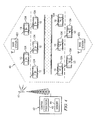
- FIGURE 4 shows one embodiment 40 of an RF system being tested by a plurality of mobile probes, such as probes 10 mounted on a plurality of vehicles 104.
- RF is shown being transmitted to/from tower 41 (or via a base station 401) under control of control system 42 (which could be at a base-station).
- Processor 43 and memory 44 monitor and control the test measurements.
- the signals from each probe can be sent on the cellular signals to the tower or they can be communicated via different protocol.
- the probe signals could, for example, be sent from each vehicle 104 to various control points, such as points 401, and then gathered by control 42, if desired. Points 401 could be fixed, or mobile, or a combination thereof.
- each probe When attacking this problem with 100s or 1000s of inexpensive probes, each probe would measure and record only a few handoff measurement artifacts.
- network bandwidth is available, (or when a mobile probe comes within range of a collection point) that probe transmits its stored measurements to a higher-level server.
- the higher-level source such as control 42, can aggregate the data from a large number probes and analyze that data for signal problems.
- One problem is how to configure each probe to make the measurement of interest.
- An approach is to use a statistical system such that each probe only measures a sub-set of the possible test measurements, but taken together over all of probes, all the desired test measurements are obtained.
- One system for implementing such an approach is to have every probe generate a random number (e.g. between 0 and 1) via, for example, random number generator (RNG) 103 (FIGURE 1), and then have that probe compare that number to some probability threshold for a given measurement type.
- the probability threshold could be built into each probe or could be downloaded from time to time dependent upon what measurements are desired over the entire measurement area. For example, as the probe transitions between cell sectors (i.e.
- the probe tests its random number (say 0.345) against a threshold (say 0.05). If the random number is below that threshold, then the probe proceeds with acquiring and storing the measurement. In this example, the probe would not perform the measurement because it's random number 0.345 is above the threshold. This same "lottery" approach can be followed for each possible measurement. Because of the random statistically based nature of the results, and the large number of probes, a sufficient number of tests of each type will be performed.
- the probe Once the probe is simplified, its energy efficiency improves. The goal is to get the probe's energy requirements below the energy available from the integrated photovoltaic and/or micro-turbine wind generator. Rechargeable batteries allow the probe to operate during periods when generated power is not available.
- one or more probes can function as a data recorder and the test results stored, for example, in a flash memory that can be removed for uploading to a database for processing.
- the vehicle or the test probe
- the vehicle can be physically linked (by wire or IR, etc.) for the upload of its information.
- the "routine" test results could be communicated in this manner while the critical data could be transmitted to a control location.
- the system and method discussed herein can, in addition to use for testing an RF signal, can be employed for any number of testing scenarios.
- the device can have an opening for receiving air-borne substances, such as pollen, toxic material, radiation, etc., or any other type of input, such as sunlight, noise, vibration, images etc., for testing.
- air-borne substances such as pollen, toxic material, radiation, etc.
- any other type of input such as sunlight, noise, vibration, images etc.
Landscapes
- Engineering & Computer Science (AREA)
- Computer Networks & Wireless Communication (AREA)
- Signal Processing (AREA)
- Quality & Reliability (AREA)
- Physics & Mathematics (AREA)
- Electromagnetism (AREA)
- Arrangements For Transmission Of Measured Signals (AREA)
- Mobile Radio Communication Systems (AREA)
Abstract
Description
Claims (10)
- A method of performing wireless communication test measurements; said method including the steps of:deploying a large number of test probes (10), each probe being deployed on a mobile vehicle (104) and each probe containing the ability to test a wide variety of wireless communication parameters;obtaining from time to time any specific one of said test probes at a location external to all of said test probes the results of a specific one of said tested parameters, said specific tested parameter being randomly selected, said obtaining occurring while said mobile vehicle to which said specific test probe is deployed is moving from place to place; andwherein said deploying is accomplished without invasive attachment of said test probes to said vehicles.
- A method according to claim 1, including the step of generating within each said test probe power for controlling said test measurements.
- A method according to claim 2, including the step of generating within said test probes mobile vehicle location signals which are independent from said vehicles' electrical systems.
- A method according to claim 2 or 3, wherein said deploying step includes attaching each said test probe using a non-invasive latching mechanism (15).
- A method according to claim 2 or 3, including the step of processing at said external location the test results from a plurality of specific ones of said test probes so as to generate an understanding of said test results from said wide variety or wireless communication parameters.
- A test probe (10) for performing wireless communication test measurements; said test probe including:a housing (11);a non-invasive latching mechanism (15) for temporarily affixing said housing to an outside surface of a mobile vehicle (104);a self-generating power source (18) within said housing;an antenna (16) for receiving and transmitting RF signals;a processor (17) for controlling the performance of test measurements with respect to RF;a geographical position determination system (14); andtransmit control (17) for enabling said transmitter to send to a location external to said test probe any results from the performance of test measurements performed under control of said processor, said test results having associated therewith a location of said test probe as determined by said geographical position determination system.
- A test probe according to claim 6, including means (43) for determining which tests are performed by a particular device at a particular time.
- A test probe according to claim 7, wherein each said test measurement has associated therewith a desired probability of being activated at a particular time; and
wherein said determining means comprises a random number of generator (103) comparison with said probability for each possible test measurement to determine which test measurements will be activated at any particular time. - A test probe according to claim 6, 7 or 8, wherein the number of test measurements performed at any given time is controlled, at least in part, by the available power at said given time.
- A test probe according to claim 6, 7, 8 or 9, wherein the number of test measurements performed at any given time is controlled, at least in part, by the speed of the vehicle to which said device is attached at said given time.
Applications Claiming Priority (2)
| Application Number | Priority Date | Filing Date | Title |
|---|---|---|---|
| US869695 | 1992-04-16 | ||
| US10/869,695 US20050282537A1 (en) | 2004-06-16 | 2004-06-16 | System and method for improving wireless measurements |
Publications (2)
| Publication Number | Publication Date |
|---|---|
| EP1608090A2 true EP1608090A2 (en) | 2005-12-21 |
| EP1608090A3 EP1608090A3 (en) | 2007-10-03 |
Family
ID=35124481
Family Applications (1)
| Application Number | Title | Priority Date | Filing Date |
|---|---|---|---|
| EP05253143A Withdrawn EP1608090A3 (en) | 2004-06-16 | 2005-05-20 | System and method for improving wireless measurements on a vehicle |
Country Status (2)
| Country | Link |
|---|---|
| US (1) | US20050282537A1 (en) |
| EP (1) | EP1608090A3 (en) |
Families Citing this family (2)
| Publication number | Priority date | Publication date | Assignee | Title |
|---|---|---|---|---|
| ES2314761T3 (en) * | 2006-02-03 | 2009-03-16 | Siemens Aktiengesellschaft | METHOD FOR SOFTENING ALTERNATE ELECTRIC CURRENT FROM A SERIES OF ENERGY GENERATION UNITS AND WIND PLANT THAT INCLUDES A SERIES OF WIND MILLS WITH VARIABLE ROTATION SPEED. |
| US7551130B2 (en) * | 2007-11-21 | 2009-06-23 | General Electric Company | Wind turbine with data receiver |
Family Cites Families (15)
| Publication number | Priority date | Publication date | Assignee | Title |
|---|---|---|---|---|
| US4397041A (en) * | 1980-03-03 | 1983-08-02 | Pioneer Electronic Corporation | Complex antenna system and FM/AM receiver |
| US4535333A (en) * | 1982-09-23 | 1985-08-13 | Chamberlain Manufacturing Corporation | Transmitter and receiver for controlling remote elements |
| US4611320A (en) * | 1984-05-21 | 1986-09-09 | Siemens Corporate Research And Support, Inc. | Programmable testing analyzer |
| US5251815A (en) * | 1992-12-18 | 1993-10-12 | American Standard Inc. | Self powered and balancing air damper |
| NO940977L (en) * | 1993-04-06 | 1994-10-05 | Alcatel Str Ag | Method and apparatus for ensuring the quality of service in a mobile radio system |
| FI106589B (en) * | 1996-09-27 | 2001-02-28 | Nokia Networks Oy | Adaptive frequency planning in a cellular network |
| US6480718B1 (en) * | 1999-07-12 | 2002-11-12 | Nortel Networks Limited | Automatic frequency planning for a wireless network |
| GB2360173B (en) * | 2000-03-07 | 2004-04-07 | Hewlett Packard Co | Distributed telemetry method and system |
| CN1426510A (en) * | 2000-03-08 | 2003-06-25 | 里索国家实验室 | Method of operating turbine |
| US6757543B2 (en) * | 2001-03-20 | 2004-06-29 | Keynote Systems, Inc. | System and method for wireless data performance monitoring |
| WO2003030416A1 (en) * | 2001-10-01 | 2003-04-10 | Summitek Instruments, Inc. | Portable device used to measure passive intermodulation in radio frequency communication systems |
| US7123876B2 (en) * | 2001-11-01 | 2006-10-17 | Motia | Easy set-up, vehicle mounted, in-motion tracking, satellite antenna |
| US20030162539A1 (en) * | 2002-02-28 | 2003-08-28 | Fiut Brian D. | System and method for remote monitoring of basestations |
| US7315739B2 (en) * | 2002-11-27 | 2008-01-01 | Agilent Technologies, Inc. | Systems and methods for measurement and/or control using mobile probes |
| JP2005150824A (en) * | 2003-11-11 | 2005-06-09 | Hitachi Ltd | Sensor with wireless function |
-
2004
- 2004-06-16 US US10/869,695 patent/US20050282537A1/en not_active Abandoned
-
2005
- 2005-05-20 EP EP05253143A patent/EP1608090A3/en not_active Withdrawn
Also Published As
| Publication number | Publication date |
|---|---|
| EP1608090A3 (en) | 2007-10-03 |
| US20050282537A1 (en) | 2005-12-22 |
Similar Documents
| Publication | Publication Date | Title |
|---|---|---|
| Kaivonen et al. | Real-time air pollution monitoring with sensors on city bus | |
| US10580232B2 (en) | Apparatus and method that diagnose vehicle health condition | |
| JP6408535B2 (en) | Emission measurement device | |
| CN112179487B (en) | Automatic detection system and monitoring method for airport environmental noise | |
| EP3025926B1 (en) | Condition monitoring system for monitoring a condition of a bearing unit for a vehicle | |
| US8130103B2 (en) | Method of reducing power consumption of a radio badge in a boundary detection localization system | |
| Lin et al. | Wireless communication performance based on IEEE 802.11 p R2V field trials | |
| Rubio-Aparicio et al. | An embedded crowdsensing unit for mobile urban pollution monitoring | |
| Molisch et al. | Millimeter-wave V2X channel measurements in urban environments | |
| EP4471522A1 (en) | Method for capturing voltage-based events in motor vehicles | |
| CN102506016A (en) | Wind power station equipment status inspection device | |
| US20050282537A1 (en) | System and method for improving wireless measurements | |
| CN107103653A (en) | A kind of vehicle intelligent terminal system | |
| CN104717609A (en) | LTE network detection method, device and system for railway | |
| US11619673B2 (en) | Lifetime battery tracking using a wireless interface | |
| RU2505861C1 (en) | Apparatus for controlling and recording fuel consumption on vehicle | |
| US20050288009A1 (en) | Method and apparatus for objective measurement of wireless service performance and coverage | |
| Pei et al. | Critical design parameters and operating conditions of wireless sensor units for structural health monitoring | |
| CN106950893A (en) | Logistic transportation supervision system and method | |
| Xhafka et al. | Mobile environmental sensing and sustainable public transportation using ICT Tools | |
| CN106714282A (en) | Wireless network system | |
| JP2002152975A (en) | Windmill power generation system | |
| Liu et al. | Measurement and analysis of LoRa transmission performance in subway station | |
| Haldar et al. | An IoT based battery condition monitoring system for electric vehicles | |
| CN213522372U (en) | Anti-collision system and positioning alarm equipment in closed coal bunker |
Legal Events
| Date | Code | Title | Description |
|---|---|---|---|
| PUAI | Public reference made under article 153(3) epc to a published international application that has entered the european phase |
Free format text: ORIGINAL CODE: 0009012 |
|
| AK | Designated contracting states |
Kind code of ref document: A2 Designated state(s): AT BE BG CH CY CZ DE DK EE ES FI FR GB GR HU IE IS IT LI LT LU MC NL PL PT RO SE SI SK TR |
|
| AX | Request for extension of the european patent |
Extension state: AL BA HR LV MK YU |
|
| RAP1 | Party data changed (applicant data changed or rights of an application transferred) |
Owner name: AGILENT TECHNOLOGIES, INC. |
|
| PUAL | Search report despatched |
Free format text: ORIGINAL CODE: 0009013 |
|
| AK | Designated contracting states |
Kind code of ref document: A3 Designated state(s): AT BE BG CH CY CZ DE DK EE ES FI FR GB GR HU IE IS IT LI LT LU MC NL PL PT RO SE SI SK TR |
|
| AX | Request for extension of the european patent |
Extension state: AL BA HR LV MK YU |
|
| 17P | Request for examination filed |
Effective date: 20080327 |
|
| AKX | Designation fees paid |
Designated state(s): DE FR GB |
|
| 17Q | First examination report despatched |
Effective date: 20080910 |
|
| STAA | Information on the status of an ep patent application or granted ep patent |
Free format text: STATUS: THE APPLICATION IS DEEMED TO BE WITHDRAWN |
|
| 18D | Application deemed to be withdrawn |
Effective date: 20090121 |