EP1608036A2 - Earphone antenna, composite coil used therefor, coaxial cable, and radio device with the earphone antenna - Google Patents
Earphone antenna, composite coil used therefor, coaxial cable, and radio device with the earphone antenna Download PDFInfo
- Publication number
- EP1608036A2 EP1608036A2 EP04710473A EP04710473A EP1608036A2 EP 1608036 A2 EP1608036 A2 EP 1608036A2 EP 04710473 A EP04710473 A EP 04710473A EP 04710473 A EP04710473 A EP 04710473A EP 1608036 A2 EP1608036 A2 EP 1608036A2
- Authority
- EP
- European Patent Office
- Prior art keywords
- audio
- frequency
- signal lines
- earphone
- signals
- Prior art date
- Legal status (The legal status is an assumption and is not a legal conclusion. Google has not performed a legal analysis and makes no representation as to the accuracy of the status listed.)
- Withdrawn
Links
Images



Classifications
-
- H—ELECTRICITY
- H01—ELECTRIC ELEMENTS
- H01Q—ANTENNAS, i.e. RADIO AERIALS
- H01Q1/00—Details of, or arrangements associated with, antennas
- H01Q1/44—Details of, or arrangements associated with, antennas using equipment having another main function to serve additionally as an antenna, e.g. means for giving an antenna an aesthetic aspect
-
- H—ELECTRICITY
- H01—ELECTRIC ELEMENTS
- H01Q—ANTENNAS, i.e. RADIO AERIALS
- H01Q1/00—Details of, or arrangements associated with, antennas
- H01Q1/12—Supports; Mounting means
- H01Q1/22—Supports; Mounting means by structural association with other equipment or articles
- H01Q1/24—Supports; Mounting means by structural association with other equipment or articles with receiving set
- H01Q1/241—Supports; Mounting means by structural association with other equipment or articles with receiving set used in mobile communications, e.g. GSM
- H01Q1/242—Supports; Mounting means by structural association with other equipment or articles with receiving set used in mobile communications, e.g. GSM specially adapted for hand-held use
-
- H—ELECTRICITY
- H01—ELECTRIC ELEMENTS
- H01P—WAVEGUIDES; RESONATORS, LINES, OR OTHER DEVICES OF THE WAVEGUIDE TYPE
- H01P5/00—Coupling devices of the waveguide type
- H01P5/08—Coupling devices of the waveguide type for linking dissimilar lines or devices
- H01P5/10—Coupling devices of the waveguide type for linking dissimilar lines or devices for coupling balanced lines or devices with unbalanced lines or devices
-
- H—ELECTRICITY
- H01—ELECTRIC ELEMENTS
- H01Q—ANTENNAS, i.e. RADIO AERIALS
- H01Q1/00—Details of, or arrangements associated with, antennas
- H01Q1/12—Supports; Mounting means
- H01Q1/22—Supports; Mounting means by structural association with other equipment or articles
- H01Q1/24—Supports; Mounting means by structural association with other equipment or articles with receiving set
-
- H—ELECTRICITY
- H01—ELECTRIC ELEMENTS
- H01Q—ANTENNAS, i.e. RADIO AERIALS
- H01Q1/00—Details of, or arrangements associated with, antennas
- H01Q1/27—Adaptation for use in or on movable bodies
- H01Q1/273—Adaptation for carrying or wearing by persons or animals
-
- H—ELECTRICITY
- H01—ELECTRIC ELEMENTS
- H01Q—ANTENNAS, i.e. RADIO AERIALS
- H01Q1/00—Details of, or arrangements associated with, antennas
- H01Q1/44—Details of, or arrangements associated with, antennas using equipment having another main function to serve additionally as an antenna, e.g. means for giving an antenna an aesthetic aspect
- H01Q1/46—Electric supply lines or communication lines
-
- H—ELECTRICITY
- H01—ELECTRIC ELEMENTS
- H01Q—ANTENNAS, i.e. RADIO AERIALS
- H01Q9/00—Electrically-short antennas having dimensions not more than twice the operating wavelength and consisting of conductive active radiating elements
- H01Q9/04—Resonant antennas
- H01Q9/16—Resonant antennas with feed intermediate between the extremities of the antenna, e.g. centre-fed dipole
-
- H—ELECTRICITY
- H04—ELECTRIC COMMUNICATION TECHNIQUE
- H04R—LOUDSPEAKERS, MICROPHONES, GRAMOPHONE PICK-UPS OR LIKE ACOUSTIC ELECTROMECHANICAL TRANSDUCERS; ELECTRIC HEARING AIDS; PUBLIC ADDRESS SYSTEMS
- H04R1/00—Details of transducers, loudspeakers or microphones
- H04R1/10—Earpieces; Attachments therefor ; Earphones; Monophonic headphones
- H04R1/1033—Cables or cables storage, e.g. cable reels
Definitions
- the present invention relates to a so-called earphone antenna in which earphones are connected to wireless equipment for reproducing audio (emitting sound), and cords of which are used as an antenna.
- the invention relates to an earphone antenna, a composite coil used therefor, likewise, a coaxial cable used for the earphone antenna, and a wireless device provided with the earphone antenna, which are capable of obtaining a high receiving sensitivity over a wide range of frequencies without performing sensitivity adjusting operation or receiving frequency switching operation, and which are not subject to negative influence from the human body through the earphones.
- an antenna for a wireless device that receives high-frequency electrical waves
- one using earphones themselves, one formed by arranging conductor lines within a housing of the wireless device, and the like have typically been used. It has been difficult to obtain a sufficient receiving sensitivity with these antennas.
- a loop antenna introduced in Japanese Patent Application Publication No. 10-84209 has been developed. Antennas of this type have a configuration that a loop antenna is attached to a neck strap of a small-sized wireless device, and that an inductance element is connected in parallel to the loop antenna in such an orientation that a plane of its aperture faces perpendicularly to the surface of the human body.
- an earphone antenna disclosed in Japanese Patent Application Publication No. 6-22331, has been developed, for example, in which signal lines to earphones are assembled with an antenna for integration into a helmet.
- the antenna of the type introduced by, e.g., Japanese Patent Application Publication No. 10-84209 mentioned above and the like has addressed an issue, first of all, that no consideration is given to the integration of earphones thereinto.
- the earphone antenna in which audio signal lines to earphones are integrated with an antenna has addressed an issue that the human body exerts serious influence upon a wireless device through the antenna due to the earphones directly touching the human body, and that stability of reception is greatly compromised. Furthermore, the fact that a matching section of the antenna and an equipment section such as a tuner are placed within the same equipment has imposed another problem that the earphone antenna is susceptible to noises of the equipment.
- so-called portable liquid-crystal TVs needs to receive high-frequency signals over a very wide band of 90 to 770 MHz.
- usable frequencies include 90-108 MHz (1-3 channels), 170-220 MHz (4-12 channels) in the VHF band, and usable frequencies include 470-770 MHz (13-62 channels) in the UHF band.
- a sensitivity adjusting means For example, a sensitivity adjusting component into which a magnetic substance is movably inserted is provided to adjust the amount of insertion of the magnetic substance in accordance with a frequency for reception.
- a sensitivity adjusting means there has been an inconvenience that sensitivity adjustment must be made every time the frequency for reception is switched.
- the present invention has been made in order to overcome such problems, and an object thereof is to provide an earphone antenna which can eliminate high frequency-derived negative influence exerted upon a receiver side from the human body via earphones, and further, which can remove influence of noises of the equipment by isolating an antenna section from the receiving equipment, ensure a receiving sensitivity required for a wide band of frequencies without involving sensitivity adjusting operation, and also transmit audio signals of a television receiver to earphone units, and a composite coil and a coaxial cable used therefore, and a wireless device provided with the earphone antenna.
- An earphone antenna as claimed in Claim 1 has a balun for converting a balanced mode into an unbalanced mode, and has a pair of audio/high-frequency dual-function signal lines for connection to a left earphone unit and a pair of audio/high-frequency dual-function signal lines for connection to a right earphone unit, connected to terminals on a balanced-mode side of the above-mentioned balun.
- the earphone antenna is characterized by being configured such that the above-mentioned two pairs of audio/high-frequency dual-function signal lines function as a receiving antenna for high-frequency signals, and the above-mentioned two pairs of audio/high-frequency dual-function signal lines function as audio signal transmission means to the above-mentioned left and right earphone units for audio signals.
- the above-mentioned balun performs impedance conversion from the balanced mode into the unbalanced mode, and further, the above-mentioned two pairs of audio/high-frequency dual-function signal lines are caused to function as a receiving antenna for high-frequency signals, and as audio signal transmission means for audio signals.
- integration of the high-frequency receiving antenna with the earphones can be implemented.
- a wireless device as claimed in Claim 3 is characterized by including the above-mentioned earphone antenna as claimed in Claim 1, and a receiving apparatus connected to a terminal on an unbalanced side of the above-mentioned balun of the above-mentioned earphone antenna via a cable.
- An earphone antenna as claimed in Claim 4 is characterized by having a balun for converting a balanced mode into an unbalanced mode, having a pair of audio/high-frequency dual-function signal lines corresponding to the above-mentioned left earphone unit and a pair of audio/high-frequency dual-function signal lines corresponding to a right earphone unit, connected to terminals on a balanced-mode side of the above-mentioned balun, and having terminals on a non-balun side of each of the above-mentioned pairs of audio/high-frequency dual-function signal lines connected to a corresponding one of the above-mentioned earphone units via respective loading coils.
- the above-mentioned respective loading coils are configured to have high impedance for signals having a specific frequency (e.g., 200 MHz) having a frequency higher than a pre-set fundamental frequency (e.g., 100 MHz) for isolation from the above-mentioned two pairs of audio/high-frequency dual-function signal lines in terms of high frequency to cause the above-mentioned signal lines to function as a dipole antenna, and have low impedance for signals having the above-mentioned fundamental frequency (e.g., 100 MHz) to combine the above-mentioned respective loading coils with the above-mentioned two pairs of audio/high-frequency dual-function signal lines in terms of high frequency by connection so as to function as a dipole antenna formed from both.
- the above-mentioned respective pairs of audio/high-frequency dual-function signal lines are configured to function as audio signal transmission means for audio signals to the above-mentioned left and right earphone units.
- a high-frequency signal can be mode-converted from the balanced mode into the unbalanced mode at the above-mentioned balun, and also the loading coils have high impedance for signals having a specific frequency (e.g., 200 MHz) higher than a fundamental frequency (e.g., 100 MHz) for isolation from the above-mentioned two pairs of audio/high-frequency dual-function signal lines whereby to cause the above-mentioned two pairs of audio/high-frequency dual-function signal lines to function as a dipole antenna for resonance.
- a specific frequency e.g. 200 MHz
- a fundamental frequency e.g. 100 MHz
- the above-mentioned loading coils have low impedance for a signal having the fundamental frequency (e.g., 100 MHz) to cause the above-mentioned two pairs of audio/high-frequency dual-function signal lines and the respective loading connected thereto to function as a dipole antenna for resonance.
- a signal having the fundamental frequency e.g. 100 MHz
- a dipole antenna that resonates at the fundamental frequency e.g., 100 MHz
- its harmonics a third harmonic at, e.g., 300 MHz
- a dipole antenna that resonates with signals having a specific frequency e.g., 200 MHz
- a pre-set frequency e.g., 100 MHz
- the loading coils shorten an antenna length required for resonance at the fundamental frequency (e.g., 100 MHz), to allow resonance to occur with signals having long wavelengths even with a short antenna length.
- the receiving sensitivity to low-frequency signals can be enhanced without unreasonably increasing the antenna length. This is an advantage that is not negligible.
- a sensitivity characteristic that exhibits relatively small variations in receiving sensitivity can be obtained over a wide frequency band, and thus no sensitivity adjustment of the earphone antenna is required at all in order to obtain the sensitivity characteristic.
- the above-mentioned respective pairs of audio/high-frequency dual-function signal lines and the above-mentioned loading coils are configured to function as audio signal transmission means for audio signals of the above-mentioned left and right earphone units.
- integration of the earphone units with the antenna can be implemented.
- the antenna can be used for reception of high-frequency signals over a wide frequency band, and used also as means for transmitting audio signals to the earphone units, whereby integration of the high-sensitivity, wide-band antenna with the earphone units becomes possible.
- a composite coil as claimed in Claim 11 is characterized by winding a plurality of conductor lines around a single core to form a plurality of coils, each of the above-mentioned coils having the same number of turns and the same impedance.
- a plurality of coils can be formed in a size substantially equal to that of a single coil, whereby it contributes to downsizing and weight reduction of devices, equipment using a plurality of coils.
- the above-mentioned respective coils constituting each of the above-mentioned composite coils are to be used as the respective loading coils in each of the above-mentioned left and right pairs of loading coils of the earphone antenna, they contribute to downsizing and weight reduction of the earphone antenna, and thus inconvenience at the time of use of the earphone antenna can be reduced.
- a wireless device as claimed in Claim 14 is characterized by including the above-mentioned earphone antenna as claimed in Claim 4, 5, 6, 7, 9, 10, 12 or 13, and a receiving apparatus connected to a terminal on an unbalanced-mode side of the above-mentioned balun.
- a coaxial cable as claimed in Claim 15 is characterized by having a central conductor for passing high-frequency signals therethrough, a first insulator for enclosing the above-mentioned central conductor, a shielding wire for enclosing the above-mentioned first insulator, a second insulator for enclosing the above-mentioned shielding wire, and a pair of audio signal lines, wound around an outer side of the above-mentioned second insulator, for transmitting left and right audio signals therethrough.
- high-frequency signals e.g., 100 MHz to 700 MHz
- left and right audio signals e.g., several tens to 20,000 Hz
- a single coaxial cable can be used for transmission of both the high-frequency signals and the left and right audio signals.
- the coaxial cable can be used in both the high-frequency signals and the left and right audio signals, and thus is most suitable as a connection means of a wireless device in which each of the above-mentioned various earphone antennas is connected to the receiving apparatus.
- An earphone antenna of the present invention basically includes a balun, and two pairs of audio/high-frequency dual-function signal lines corresponding to left and right earphones connected to terminals on a balanced-mode side of the balun.
- the two pairs of audio/high-frequency dual-function signal lines are configured to function, for high-frequency signals, as a receiving antenna, and, for audio signals, as audio signal transmission means to the left and right earphone units.
- two pairs of audio/high-frequency dual-function signal lines configured as follows.
- the two pairs of signal lines, each pair having two 15 cm-long and 11 cm-long lines that are 5 or more millimeters spaced apart from each other, are secured symmetrically to form an opening angle of 90° for connection to the balun.
- This allows a dipole antenna to be formed which can receive high-frequency signals in the entire UHF band covered by digital terrestrial broadcasting, even with no trouble in transmitting audio signals.
- high-frequency cutting means e.g., inductance elements (coils) between terminals on a non-balun side of the dipole antenna and the earphones.
- the high-frequency cutting means present high impedance for high-frequency signals (e.g., UHF waves) to cut the high-frequency signals, and present low impedance for audio signals to permit transmission of the audio signals.
- high-frequency signals e.g., UHF waves
- an earphone antenna which includes a balun and a pair of loading coils added to each of two left and right pairs of audio/high-frequency dual-function signal lines for connection to left and right earphones.
- the loading coils present high impedance or low impedance in accordance with different frequency bands, whereby the above-mentioned two pairs of audio/high-frequency dual-function signal lines function as a dipole antenna resonating with high-frequency signals having the above-mentioned specific frequency (200 MHz), and the earphone antenna formed by adding the above-mentioned pair of loading coils to each of the above-mentioned two pairs of audio/high-frequency dual-function signal lines functions also as a dipole antenna resonating at the above-mentioned fundamental frequency (100 MHz).
- a folded dipole antenna may be configured which includes one and the other of one of the two pairs of dual-function high-frequency signal lines corresponding to the left earphone unit, and one and the other of the other of the two pairs of dual-function high-frequency signal lines corresponding to the right earphone unit.
- the impedance by the antenna becomes four times, thereby permitting easy impedance matching at the
- high-frequency cutting means e.g., ferrite beads (or choke coils) between the respective pairs of audio/high-frequency dual-function signal lines in the loading coils and the above-mentioned earphones to prevent the human body exerting negative influence on reception of high-frequency signals.
- ferrite beads or choke coils
- band-expanding capacitors between the above-mentioned audio/high-frequency dual-function signal lines paired for the left and right sides, respectively. The reason is that this can expand the receiving frequency band.
- high-frequency cutting means e.g., ferrite beads (choke coils) that present high impedance for high-frequency signals
- audio signal transmission lines for transmitting audio signals in the respective pairs of audio/high-frequency dual-function signal lines of the above-mentioned dipole antenna, whereby entrance of unnecessary high-frequency signals into the audio signal lines can be prevented.
- the loading coils may be formed from separate and independent components, respectively.
- such a configuration increases the area occupied by the loading coils and hence of the loading coils having them, which would then potentially increase the size and weight of the earphone antenna.
- the earphone antenna of the present invention transmits high-frequency signals to a receiving apparatus of a wireless device that is remotely located, and receives audio signals from the receiving apparatus.
- a coaxial cable for transmission/reception of the high-frequency signals, the audio signals to/from the receiving apparatus from the viewpoint of preventing entrance of noise, enhancing stability of reception, and the like.
- coaxial cable it may be preferred to use one provided with a central conductor that passes high-frequency signals therethrough, an insulator enclosing the central conductor, a shielding wire enclosing the above-mentioned insulator, an insulator for enclosing the above-mentioned shielding wire, and left and right audio signal lines on the outer side of the above-mentioned insulator.
- a single coaxial cable can be used for transmission of both the high-frequency signals and the left and right audio signals, and thus is most suitable as a coaxial cable for connection to the receiving apparatus of a wireless device.
- it may be configurable to transmit left and right sounds using a pair of audio signal lines and the above-mentioned shielding line, it may otherwise be configurable such that, besides the above-mentioned pair of audio signal lines, a common audio signal line is wound around the outer side of the second insulator to transmit the left and right audio signals through these three common audio signal lines.
- Each of the above-mentioned signal lines may preferably be made by stranding a plurality of wires so as to impart thereto conductivity, mechanical flexibility, and the like.
- As its material for example, annealed copper is suitable.
- the two pairs of audio/high-frequency dual-function signal lines function as a U-shaped dipole antenna for signals having the above-mentioned specific frequency (e.g., 200 MHz).
- the angle may also be acceptable to set the angle to a value smaller than approximately 180°.
- the two pairs of audio/high-frequency dual-function signal lines function as a V-shaped dipole antenna for signals having the above-mentioned specific frequency (e.g., 200 MHz).
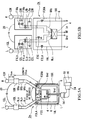
- Figs. 1A, 1B show a first embodiment of an earphone antenna of the present invention, in which Fig. 1A is a principle-illustrating configurational diagram, and Fig. 1B is an equivalent circuit diagram.
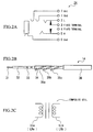
- Figs. 2A to 2C show individual components for use in the earphone antenna, in which Fig. 2A is a diagram showing a pin-jack connector; Fig. 2B is a configurational diagram of a coaxial cable; and Fig. 2C is a configurational diagram of a composite coil.
- reference symbol 2 denotes the present earphone antennal (the first embodiment of the earphone antenna of the present invention), which includes a matching box 6 for housing a balun 4 and the like, audio/high-frequency dual-function signal lines 8La, 8Lb, 8Ra, 8Rb as earphone cords connected to terminals on a balanced side of the above-mentioned balun 4, and a pair of loading boxes 10L, 10R connected to terminals on a non-balun side of the above-mentioned audio/high-frequency dual-function signal lines 8La, 8Lb, 8Ra, 8Rb.
- each of the above-mentioned audio/high-frequency dual-function signal lines 8La, 8Lb, 8Ra, 8Rb is formed by stranding a plurality of wires having conductivity, mechanical flexibility, and the like; they are made from, e.g., annealed copper. Further, as stranded wires, insulated litz wires may otherwise be used.
- the above-mentioned balun 4 converts a balanced mode into an unbalanced mode, and performs impedance conversion. From one side of the balanced-side terminal extend the left-side audio/high-frequency dual-function signal lines 8La, 8Lb, and from the other side extend the right-side audio/high-frequency dual-function signal lines 8Ra, 8Rb at a fixed angle of 30° or more (90° in the present example), for connection such that they can function as a V-shaped dipole antenna (a portion forming this V-shaped dipole is machined so as to maintain a comparatively high rigidity).
- Their length from the balun 4 to the impedance boxes 10L, 10R is set to, e.g., 37 cm or more.
- the reason for forming one side from two signal lines (8La, 8Lb on the left side and 8Ra, 8Rb on the right side) in this way is to cause these audio/high-frequency dual-function signal lines 8La, 8Lb, 8Ra, 8Rb to function not only as a receiving antenna for high-frequency signals, but also as audio signal transmission means that transmits audio signals to the respective left and right earphone units 12L, 12R.
- auxiliary antennas 8Lc, 8Rc may also be acceptable to provide auxiliary antennas 8Lc, 8Rc to supplement the characteristics. It is preferable to set the length of each of the above-mentioned auxiliary antennas 8Lc, 8Rc to, e.g., 50 mm, and provide them at least 5 mm spaced apart from corresponding ones of the audio/high-frequency dual-function signal lines 8La, 8Lb, 8Ra, 8Rb, respectively.
- the signal lines 8La, 8Lb, 8Ra, 8Rb (and 8Lc, 8Rc) having such a size and shape as shown in Fig. 1A have a function as a V-shaped dipole antenna in which resonance occurs at a 200-MHz high-frequency signal, and excites with its harmonics (a third harmonic, a fifth harmonic, a seventh harmonic).
- Terminals on an unbalanced side of the above-mentioned balun 4 are connected to, e.g., a liquid crystal TV (television receiver) 16 via a coaxial cable 14.
- the above-mentioned balun 4 used in the present embodiment is one that performs mode conversion and impedance conversion of a 200 ⁇ balanced input into a 75 ⁇ unbalanced output.
- connection between the above-mentioned coaxial cable 14 and the above-mentioned liquid-crystal TV 16 is made using a pin-jack connector having a pin arrangement shown in Fig. 2A.
- the above-mentioned coaxial cable 14 is, as shown in Fig. 2B, an integrated coaxial cable in which signal lines for high-frequency signals and signal lines for audio signals are integrated with each other, and performs transmission of high-frequency signals and transmission of left and right audio signals through the single coaxial cable. It is not necessarily essential to transmit the signal lines for high-frequency signals and the signal lines for audio signals through a single coaxial cable. Although it may be acceptable to transmit the signals through different cables, it would be preferable to transmit high-frequency signals and audio signals through a single coaxial cable because the number of cables used is small and a downsized, weight-reduced, and inexpensive cable can be implemented.
- the above-mentioned coaxial cable 14 connects between the present earphone antenna 2 and a receiving circuit (receiving apparatus) 19 of a wireless device, e.g., the liquid-crystal TV (television receiver) 16, and has a structure such as shown in Fig. 2B.
- a wireless device e.g., the liquid-crystal TV (television receiver) 16
- a wireless device e.g., the liquid-crystal TV (television receiver) 16
- the present coaxial cable 14 is formed by using, as a cable conductor, a central conductor 31 that passes high-frequency signals therethrough, and by sheathing the central conductor 31 with an insulator 32, sheathing the above-mentioned insulator 32 with a shielding wire (e.g., formed from a bare annealed copper wire) 33, sheathing the above-mentioned shielding wire 33 by winding the outer side thereof with, e.g., a tape 34, winding three audio signal lines 35a, 35b, 35c isolated from each other on the outer side of the tape 34, and covering the outer side thereof with an insulating jacket 36.
- a shielding wire e.g., formed from a bare annealed copper wire
- One of the above-mentioned three audio signal lines 35a, 35b, 35c is a left-side audio signal line, another one is a right-side audio signal line, with the rest being a common audio signal line (ground line). However, in the present embodiment, it is configured to transmit audio signals through the left and right audio signal lines and the shielding wire, while leaving the common audio signal line idle.
- left and right loading boxes 10L, 10R are inserted between the audio/high-frequency dual-function signal lines 8La, 8Lb, 8Ra, 8Rb and the left and right earphone units 12L, 12R, respectively.
- the above-mentioned loading box 10L has loading coils LLa, LLb arranged such as shown in Fig. 2C, and has ferrite beads F1La, F1Lb, as high-frequency cutting means, which are connected at one end thereof to the above-mentioned loading coils LLa, LLb, and at the other end of the ferrite beads F1La, F1Lb to the left earphone unit 12L.
- the loading box 10R has loading coils LRa, LRb, and ferrite beads F1Ra, F1Rb, as high-frequency cutting means, which are connected at one end thereof to the above-mentioned loading coils LRa, LRb, and at the other end of the ferrite beads F1Ra, F1Rb to the right earphone unit 12R.
- F1Ra, F1Rb present low impedance for audio signals ranging from 50 to 20,000 Hz, permitting transmission of audio signals between the loading coils LLa, LLb, LRa, LRb and the earphone units 12L, 12R. Further, they present high impedance for high-frequency signals to cut the signals therebetween. Therefore, they can prevent compromising stability of reception due to a high-frequency signal entering from the human body to the receiving apparatus 19 side via the earphone units 12L, 12R and the audio/high-frequency dual-function signal lines 8La, 8Lb, 8Ra, 8Rb, and the like.
- Reference symbols C2L and C2R denote band-expanding capacitors connected between terminals of the earphone units 12L and 12R, respectively, each of which has a capacitance of, e.g., 10 pF.
- Fig. 1B which is a circuit diagram, the neck strap 20 is shown by a two-dot chain line.
- Reference symbols 18L, 18R denote audio signal transmission lines, which are connected to the audio/high-frequency dual-function signal lines 8La, 8Ra via ferrite beads F2LA, F2RA (e.g., BLM18HD102SN1 (1608 SIZE) manufactured by Murata Manufacturing Co., Ltd.). And the audio/high-frequency dual-function signal lines 8Rb, 8Rb are grounded via ferrite beads F2LC, F2RC having the same property as that of the above-mentioned ferrite beads F2LA, F2RA.
- F2LA ferrite beads
- F2RA e.g., BLM18HD102SN1 (1608 SIZE) manufactured by Murata Manufacturing Co., Ltd.
- These ferrite beads F2LA, F2RA, F2LC, F2RC serve to prevent leakage of high-frequency signals into the audio signal paths.
- they present high impedance e.g., 1k ⁇ or higher
- Reference symbols C1L, C1R denote capacitors (a capacitance of, e.g., 10 pF) inserted between the audio/high-frequency dual-function signal lines 8La, 8Ra and the balanced terminals of the balun 4, respectively, for isolation of the audio/high-frequency dual-function signal lines 8La, 8Ra from the audio/high-frequency dual-function signal lines 8Lb, 8Rb, respectively.
- Reference symbols C3L, C3R denote band-expanding capacitors inserted between the audio/high-frequency dual-function signal lines 8La, 8Lb, and between the audio/high-frequency dual-function signal lines 8Ra, 8Rb, for expansion of the receiving frequency band of the antenna. However, isolation is achieved between the signal lines in the frequency band of audio signals.
- a 100-MHz resonant V-shaped dipole antenna, a 200-MHz resonant V-shaped dipole antenna, and the audio signal lines coexist. That is, it has a function as the 100-MHz resonant V-shaped dipole antenna, a function as the 200-MHz resonant U-shaped dipole antenna, and a function of transmitting the left and right audio signals to the left and right earphone units 12L, 12R.
- a V-shaped dipole antenna formed from the audio/high-frequency dual-function signal lines 8La, 8Lb, 8Ra, 8Rb and the loading coils LLa, LLb, LRa, LRb functions as a receiving antenna for resonance.
- the loading coils LLa, LLb, LRa, LRb have a resonant antenna length reducing function that reduces the antenna length required for resonance at a fundamental frequency (e.g., 100 MHz), to play the role of enhancing the receiving sensitivity for low-frequency signals even with the short antenna length.
- a fundamental frequency e.g. 100 MHz
- a dipole antenna typically requires an antenna length of as long as 0.753 meters on one side thereof for resonance at 100 MHz. This is unpractical for a portable wireless device (liquid crystal TV).
- the present earphone antenna 2 includes the loading coils LLa, LLb, LRa, LRb, and the above-mentioned resonant antenna length reducing function mentioned above permits reception of low-frequency signals at a sufficient sensitivity even with its short antenna length.
- the inductances of the loading coils LLa, LLb each are approximately 1.4 ⁇ H at 100 MHz, and this makes it possible to produce resonance with a practical antenna length suitable for hanging around the neck for signals belonging to a low frequency band (having relatively long wavelengths) within a frequency band of 100 MHz usable for television broadcasting.
- a 100-MHz resonant dipole antenna is formed with a practical antenna length, and thus resonance occurs at 100 MHz, and resonance occurs further with its harmonics (a third harmonic, a fifth harmonic, a seventh harmonic).
- the above-mentioned loading coils LLa, LLb, LRa, LRb exhibit an insertion loss of as high as 50dB (gain: -50dB) for signals having a frequency of 200 MHz, substantially isolating themselves from the audio/high-frequency dual-function signal lines 8La, 8Lb, 8Ra, 8Rb, to cause only the audio/high-frequency dual-function signal lines 8La, 8Lb, 8Ra, 8Rb to function as an antenna.
- a dipole antenna formed from only the audio/high-frequency dual-function signal lines 8La, 8Lb, 8Ra, 8Rb has an antenna length of 37 cm on one side thereof, and thus resonates with signals having the frequency of 200-MHz. Consequently, a 200-MHz resonant V-shaped dipole antenna exists which resonates with signals having the frequency of 200-MHz and excites with harmonics of 200 MHz (a third harmonic, a fifth harmonic, a seventh harmonic).
- Left and right audio signals transmitted via the cable 14 from the receiving apparatus 19 of the wireless device body 16 are transmitted to the audio/high-frequency dual-function signal lines 8La, 8Lb, 8Ra, 8Rb via the left and right signal lines 18L, 18R and an earth line, and further transmitted to the earphone units 12L, 12R via the loading boxes 10L, 10R, for reproduction of sounds at the above-mentioned earphone units 12L, 12R.
- the present earphone antenna 2 can integrate the antenna with the earphones.
- the present earphone antenna 2 functions both as a 100-MHz resonant dipole antenna and a 200-MHz resonant dipole antenna, without any sensitivity adjusting operation, and thus can obtain a sufficiently high receiving sensitivity over a wide range that sufficiently covers the frequency band usable for television broadcasting through its resonance at 100 MHz and 200 MHz and its excitation with harmonics of 100 MHz and 200 MHz (a third harmonic, a fifth harmonic, a seventh harmonic). Further, it can also transmit the left and right audio signals from the receiving apparatus 19 of the wireless device body 16 to the earphone units 12L, 12R.
- the ferrite beads F1La, F1Lb, F1Ra, F1Rb can prevent high frequency-derived negative influence exerted upon the earphone antenna 2 from the human body through the earphone units 12L, 12R, and can prevent compromising stability of reception on the side of the wireless device body 16 due to the human body.
- the loading coils LLa, LLb, LRa, LRb can even be eliminated, at the cost of some compromising receiving sensitivity.
- the band-expanding capacitors C3L, C3R are eliminated, and the audio/high-frequency dual-function signal lines 8La, 8Lb, and 8Ra, 8Rb are directly connected to the ferrite beads F1La, F1Lb, and F1Ra, F1Rb, respectively.
- an antenna can be implemented which resonates at 200 MHz with ⁇ /4, and at 100 MHz with ⁇ /8, and resonates with harmonics (a third harmonic, a fifth harmonic, a seventh harmonic) in the UHF band (470 MHz to 770 MHz).
- harmonics a third harmonic, a fifth harmonic, a seventh harmonic
- an advantage is provided which the number of components is smaller, at the cost of some lower sensitivity, than in Embodiment 1.
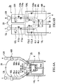
- Figs. 5A, 5B show a second embodiment 2a of an earphone antenna of the present invention, in which Fig. 5A is a configurational diagram, and Fig. 5B is a circuit diagram of the antenna.
- the present embodiment 2a is configured such that the audio/high-frequency dual-function signal lines 8Lb and 8Rb are connected to each other, and not connected to the terminals on the balanced side of the balun 4 to have a modified folded dipole antenna configuration. And a ferrite bead FBC is connected between the audio/high-frequency dual-function signal lines 8Lb, 8Rb and a ground.
- the audio signal isolating capacitors C1L, C1R are eliminated, and the terminals on the balun side of the audio/high-frequency dual-function signal lines 8Lb, 8Rb and the terminals which is on the balun side of the audio/high-frequency dual-function signal lines 8Lb, 8Rb and to which the capacitors C1L, C1R were connected are integrated with each other.
- the present embodiment 2a differs from the first embodiment 2 at these three points, but is the same save these points.
- the present embodiment 2a since it has a modified folded dipole antenna configuration, its impedance is four times that of a typical dipole antenna configuration. Therefore, there is an advantage that impedance matching at the balun 4 is made easier. Further, it has another advantage that the band is wider than with the dipole antenna.
- Figs. 6A, 6B show a third embodiment 2b of an earphone antenna of the present invention, in which Fig. 6A is a configurational diagram, and Fig. 6B is a circuit diagram of an antenna.
- the present embodiment 2b is an embodiment in which the present invention is applied to an antenna that receives digital terrestrial waves, and thus it suffices that the antenna can receive the UHF (470-770 MHz) frequencies.
- the length of each of the audio/high-frequency dual-function signal lines 8La, 8Lb, 8Ra, 8Rb is set to 15 cm, and in addition thereto, wires 8Lc, 8Rc, which are 11 cm long each, extend from lands on the balun side of the lines 8La, 8Ra. These wires 8Lc, 8Rc are 5 mm or more spaced apart from each other, and so are the lines 8Lb, 8Rb.
- the audio/high-frequency dual-function signal lines 8La, 8Lb, and 8Ra, 8Rb extend from the balun 4 so as to form an angle of, e.g., 90°, and that angle is fixed.
- ferrite beads F1La, F1Lb, F1Ra, F2Rb are connected at one end thereof to terminals on the non-balun side of the audio/high-frequency dual-function signal lines 8La, 8Lb, 8Ra, 8Rb, and at the other end of the above-mentioned ferrite beads F1La, F1Lb, F1Ra, F1Rb to the earphone units 12L, 12R.
- Reference symbols C2L, C2R denote band-expanding capacitors.
- ferrite beads F1La, F1Lb, F1Ra, F1Rb and the band-expanding capacitors C2L, C2R are accommodated within ferrite bead/capacitor boxes 40L, 40R, respectively, and the neck strap 20 is joined between the above-mentioned boxes 40L, 40R so that the antenna can be hung around the neck.
- the audio/high-frequency dual-function signal lines 8La, 8Lb, and 8Ra, 8Rb extend so as to form an angle of, e.g., 90° from the balun 4, to implement a V-shaped dipole antenna configuration, in each of the above-mentioned embodiments.
- the present invention may alternatively be embodied in such a mode as to set the angle to approximately 180° to implement a U-shaped dipole antenna configuration.
- the balun performs impedance conversion from the balanced mode into the unbalanced mode, and further, the above-mentioned two pairs of audio/high-frequency dual-function signal lines are caused to function as a receiving antenna for high-frequency signals, and as audio signal transmission means for audio signals.
- the high frequency receiving antenna with the earphones can be implemented.
- high-frequency signal cutting means are provided between the earphones and the audio/high-frequency dual-function signal lines, the high-frequency signal cutting means presenting high impedance for high-frequency signals to substantially cut the high-frequency signals, and low impedance for audio signals to permit transmission of the signals.
- a high-frequency signal can be mode-converted from the balanced mode into the unbalanced mode at the balun, and also the loading coils present high impedance for signals having a specific frequency (e.g., 200 MHz) higher than a fundamental frequency (e.g., 100 MHz) for isolation from the above-mentioned two pairs of audio/high-frequency dual-function signal lines whereby to cause the above-mentioned audio/high-frequency dual-function signal lines to function as a dipole antenna for resonance.
- a specific frequency e.g. 200 MHz
- a fundamental frequency e.g. 100 MHz
- the above-mentioned loading coils present low impedance for signals having the fundamental frequency (e.g., 100 MHz) to cause the above-mentioned two pairs of audio/high-frequency dual-function signal lines and the respective loading connected thereto to function as a dipole antenna for resonance.
- the fundamental frequency e.g. 100 MHz
- a dipole antenna that resonates at the fundamental frequency e.g., 100 MHz
- its harmonics a third harmonic at, e.g., 300 MHz
- a dipole antenna that resonates with signals having a specific frequency e.g., 200 MHz
- a pre-set frequency e.g., 100 MHz
- excites with its harmonics a third harmonic at, e.g., 600 MHz, and the like
- the loading coils shorten an antenna length required for resonance at the fundamental frequency (e.g., 100 MHz), to allow resonance to occur with signals having long wavelengths even with a short antenna length.
- the receiving sensitivity to low-frequency signals can be enhanced without unreasonably increasing the antenna length. This is an advantage that is not negligible.
- a sensitivity characteristic that exhibits relatively small variations in receiving sensitivity can be obtained over a wide frequency band, and thus no sensitivity adjustment of the earphone antenna is required at all in order to obtain the sensitivity characteristic.
- the above-mentioned respective pairs of audio/high-frequency dual-function signal lines and the above-mentioned loading coils are configured to function as audio signal transmission means for audio signals of the above-mentioned left and right earphone units.
- integration of the earphone units with the antenna can be implemented.
- the antenna can be used for reception of high-frequency signals over a wide frequency band, and used also as means for transmitting audio signals to the earphone units, whereby integration of the high-sensitivity, wide-band antenna with the earphones becomes possible.
- the earphone antenna as claimed in Claim 5 it is configured to form a folded dipole antenna.
- its impedance becomes four times that of a typical dipole antenna configuration. Therefore, there is an advantage that impedance matching at the balun is made easier.
- one and the other of the two pairs of audio/high-frequency dual-function signal lines form an angle of approximately 180°, the one and the other of the two pairs being in portions of the two pairs which are on a side connected to the terminals on the balanced-mode side of the balun.
- the two pairs of audio/high-frequency dual-function signal lines function as a U-shaped dipole antenna for the high-frequency signals having the above-mentioned specific frequency.
- one and the other of the two pairs of audio/high-frequency dual-function signal lines form an angle smaller than 180°, the one and the other of the two pairs being in portions of the two pairs which are on a side connected to the terminals on the balanced-mode side of the balun.
- the two pairs of audio/high-frequency dual-function signal lines function as a V-shaped dipole antenna for the high-frequency signals having the above-mentioned specific frequency.
- a high-frequency cutting means is provided between the audio/high-frequency dual-function signal lines and each of the earphone units, the high-frequency cutting means presenting high impedance for high-frequency signals for isolation therebetween in terms of high frequency, and presenting low impedance for audio signals to permit transmission of the audio signals.
- a band-expanding capacitor is connected between audio/high-frequency dual-function signal lines in each of the left and right pairs, and thus frequency characteristics in receiving sensitivity as an antenna can be expanded toward the lower frequency side.
- a high-frequency cutting means presenting high impedance for high-frequency signals is inserted into a audio signal line for transmitting a audio signal to the audio/high-frequency dual-function signal lines, and thus leakage of received high-frequency signals from the audio/high-frequency dual-function signal lines to the audio signal lines can be prevented.
- a plurality of conductor lines are wound around a single core to form a plurality of coils, each of the coils having the same number of turns and the same impedance.
- a plurality of coils can be formed by occupying an area and a volume substantially as small as one coil, and consequently, devices and the like using a plurality of coils can be downsized and weight-reduced.
- the above-mentioned composite coil is used as each of the left and right pairs of loading coils, and thus the size of four loading coils can be reduced to that for two coils.
- the above-mentioned earphone antenna is used, and thus advantages provided by the above-mentioned earphone antenna can be enjoyed.
- both high-frequency signals and the pair of left and right audio signal lines can be transmitted by a single cable.
- a plurality of cables i.e., a cable for transmitting the high-frequency signal and a cable for transmitting a pair of left and right audio signals, any longer.
- the coaxial cable is used for connection between the balun and the receiving apparatus.
- a cable for transmitting the high-frequency signal and a cable for transmitting a pair of left and right audio signals, any longer. Consequently, only one coaxial cable would do.
Landscapes
- Engineering & Computer Science (AREA)
- Computer Networks & Wireless Communication (AREA)
- Details Of Aerials (AREA)
- Input Circuits Of Receivers And Coupling Of Receivers And Audio Equipment (AREA)
- Headphones And Earphones (AREA)
- Support Of Aerials (AREA)
- Transceivers (AREA)
Abstract
Description
Claims (16)
- An earphone antenna having a balun for converting a balanced mode into an unbalanced mode, and a pair of audio/high-frequency dual-function signal lines for connection to a left earphone unit and a pair of audio/high-frequency dual-function signal lines for connection to a right earphone unit, connected to terminals on a balanced-mode side of said balun, said earphone antenna characterized by being configured such that:said two pairs of audio/high-frequency dual-function signal lines function as a receiving antenna for high-frequency signals, and said two pairs of audio/high-frequency dual-function signal lines function as audio signal transmission means to said left and right earphone units for audio signals.
- The earphone antenna according to claim 1, characterized by:a high-frequency signal cutting means provided between said left and right earphone units and said respective audio/high-frequency dual-function signal lines connected thereto, having high impedance against high-frequency signals to substantially cut the high-frequency signals, and low impedance for audio signals to permit transmission of the signals.
- A wireless device characterized by an earphone antenna having a balun for converting a balanced mode into an unbalanced mode, a pair of audio/high-frequency dual-function signal lines for connection to a left earphone unit and a pair of audio/high-frequency dual-function signal lines for connection to a right earphone unit, connected to terminals on a balanced-mode side of said balun, and configured such that said two pairs of audio/high-frequency dual-function signal lines function as a receiving antenna for high-frequency signals, and said two pairs of audio/high-frequency dual-function signal lines function as audio signal transmission means to said left and right earphone units for audio signals; and a receiving apparatus connected to a terminal on an unbalanced side of said balun of said earphone antenna via a cable.
- An earphone antenna having a balun for converting a balanced mode into an unbalanced mode, a pair of audio/high-frequency dual-function signal lines corresponding to said left earphone unit and a pair of audio/high-frequency dual-function signal lines corresponding to a right earphone unit, connected to terminals on a balanced-mode side of said balun, and terminals on a non-balun side of each of said pairs of audio/high-frequency dual-function signal lines connected to a corresponding one of said earphone units via respective loading coils;
wherein said respective loading coils are configured to have high impedance for signals having a specific frequency higher than a pre-set fundamental frequency for isolation from said two pairs of audio/high-frequency dual-function signal lines in terms of high frequency to cause said signal lines to function as a dipole antenna, and have low impedance for signals having said fundamental frequency to combine said respective loading coils with said two pairs of audio/high-frequency dual-function signal lines in terms of high frequency by connection to cause a dipole antenna formed from both to function; and
further, said respective pairs of audio/high-frequency dual-function signal lines are configured to function as audio signal transmission means for audio signals to said left and right earphone units. - The earphone antenna according to claim 4, characterized by being configured to:connect only one among the pair of audio/high-frequency dual-function signal lines for connection to said left and right earphone units, to a terminal on the balanced side of said balun;connect together the others of said pair of audio/high-frequency dual-function signal lines in terms of high frequency; andto form a folded dipole antenna from said one and other of the pair of audio/high-frequency dual-function signal lines corresponding to said left earphone unit, and said one and other of the pair of audio/high-frequency dual-function signal lines corresponding to said right earphone unit.
- The earphone antenna according to claim 1, 2, 4, or 5, characterized in that:one and other of said two pairs of audio/high-frequency dual-function signal lines form an angle of approximately 180°, wherein said one and other of said two pairs are in portions of said two pairs which are on a side connected to the terminals on the balanced-mode side of said balun, and said two pairs of audio/high-frequency dual-function signal lines function as a U-shaped dipole antenna for the signals having said specific frequency.
- The earphone antenna according to claim 1, 2, 4, or 5, characterized in that:one and other of said two pairs of audio/high-frequency dual-function signal lines form an angle smaller than 180°, wherein said one and other of said two pairs are in portions of said two pairs which are on a side connected to the terminals on the balanced-mode side of said balun, and said two pairs of audio/high-frequency dual-function signal lines function as a V-shaped dipole antenna for the signals having said specific frequency.
- The earphone antenna according to claim 4, 5, 6 or 7, characterized in that:a high-frequency cutting means is provided between said pair of audio/high-frequency dual-function signal lines corresponding to each of said pair of left and right loading coils, and each of said earphone units, wherein said high-frequency cutting means has high impedance for high-frequency signals to isolate therebetween in terms of high frequency, and has low impedance for audio signals to permit transmission of the audio signals.
- The earphone antenna according to claim 1, 2, 4, 5, 6, 7 or 8, characterized by connecting:a band-expanding capacitor between audio/high-frequency dual-function signal lines in each of said left and right pairs.
- The earphone antenna according to claim 1, 2, 4, 5, 6, 7, 8 or 9, characterized by having:an audio signal transmission path for transmitting a audio signal to said audio/high-frequency dual-function signal lines of said dipole antenna; andinserting a high-frequency cutting means having high impedance for high-frequency signals, into said audio signal transmission path.
- A composite coil characterized by having a plurality of conductor lines wound around a single core to form a plurality of coils having a same number of turns and same impedance.
- The earphone antenna according to claim 4, 5, 6, 7, 8, 9 or 10 characterized by two composite coils, each having a plurality of coils formed on a single core and having a same number of turns and same impedance, and
using each of said coils constituting said composite coils as respective loading coils of each of said left and right pairs. - The earphone antenna according to claim 1, 2, 4, 5, 6, 7, 8, 9, 10 or 12, characterized by joining a neck strap between portions each provided with said pair of loading coils.
- A wireless device characterized by:said earphone antenna according to claim 4, 5, 6, 7, 9, 10, 12 or 13; anda receiving apparatus connected to a terminal on an unbalanced-mode side of said balun.
- A coaxial cable characterized by:a central conductor for passing high-frequency signals therethrough;a first insulator for enclosing said central conductor;a shielding wire for enclosing said first insulator;a second insulator for enclosing said shielding wire; anda pair of audio signal lines, wound around an outer side of said second insulator, for transmitting left and right audio signals therethrough.
- A wireless device according to claim 3 or 14, characterized by:using a coaxial cable for connection between said balun and said receiving apparatus, wherein said coaxial cable has a central conductor for passing high-frequency signals therethrough, a first insulator for enclosing said central conductor, a shielding wire for enclosing said first insulator, a second insulator for enclosing said shielding wire, and a pair of audio signal lines, wound around an outer side of said second insulator, for transmitting left and right audio signals therethrough, andusing said central conductor and said shielding wire of said coaxial cable for transmission of the high-frequency signal, and said respective audio signal lines for transmission of the audio signals.
Applications Claiming Priority (3)
| Application Number | Priority Date | Filing Date | Title |
|---|---|---|---|
| JP2003052874 | 2003-02-28 | ||
| JP2003052874A JP4363865B2 (en) | 2003-02-28 | 2003-02-28 | Earphone antenna and radio |
| PCT/JP2004/001485 WO2004077606A2 (en) | 2003-02-28 | 2004-02-12 | Earphone antenna, composite coil used therefor, coaxial cable, and radio device with the earphone antenna |
Publications (2)
| Publication Number | Publication Date |
|---|---|
| EP1608036A2 true EP1608036A2 (en) | 2005-12-21 |
| EP1608036A4 EP1608036A4 (en) | 2014-03-26 |
Family
ID=32923418
Family Applications (1)
| Application Number | Title | Priority Date | Filing Date |
|---|---|---|---|
| EP04710473.2A Withdrawn EP1608036A4 (en) | 2003-02-28 | 2004-02-12 | HEADPHONE ANTENNA, USED COMPOUND COIL, COAXIAL CABLE AND RADIO EQUIPMENT WITH HEADPHONE ANTENNA |
Country Status (6)
| Country | Link |
|---|---|
| US (1) | US7236137B2 (en) |
| EP (1) | EP1608036A4 (en) |
| JP (1) | JP4363865B2 (en) |
| KR (3) | KR20060015461A (en) |
| CN (1) | CN100550515C (en) |
| WO (1) | WO2004077606A2 (en) |
Cited By (1)
| Publication number | Priority date | Publication date | Assignee | Title |
|---|---|---|---|---|
| WO2008040399A1 (en) * | 2006-10-06 | 2008-04-10 | Sony Ericsson Mobile Communications Ab | Integrated television antenna for a portable communication device |
Families Citing this family (42)
| Publication number | Priority date | Publication date | Assignee | Title |
|---|---|---|---|---|
| JP4003671B2 (en) * | 2003-03-07 | 2007-11-07 | ソニー株式会社 | Earphone antenna and radio equipped with the same |
| JP3880571B2 (en) * | 2003-10-29 | 2007-02-14 | Necアクセステクニカ株式会社 | Antenna device |
| JP4026648B2 (en) * | 2004-04-19 | 2007-12-26 | ソニー株式会社 | Earphone antenna and portable radio equipped with the earphone antenna |
| JP3933148B2 (en) * | 2004-06-04 | 2007-06-20 | ソニー株式会社 | Earphone antenna and portable radio equipped with the earphone antenna |
| TWI277355B (en) * | 2004-07-08 | 2007-03-21 | Sony Corp | Earphone antenna connecting device and portable wireless device |
| JP2006041826A (en) * | 2004-07-26 | 2006-02-09 | Matsushita Electric Ind Co Ltd | Mobile phone equipment |
| DE602005006016T2 (en) * | 2004-12-02 | 2009-05-07 | Koninklijke Philips Electronics N.V. | MOBILE TELEPHONE WITH BUILT-IN PLANAR TELEVISION ANTENNA FOR THE REMOVAL OF RADIO PHONE SIGNALS |
| JP4961125B2 (en) * | 2005-03-01 | 2012-06-27 | パナソニック株式会社 | Antenna device and wireless device |
| TWM277119U (en) * | 2005-05-10 | 2005-10-01 | Prime Electronics & Satellitics Inc | Neck-hanging antenna |
| JP4123262B2 (en) | 2005-10-07 | 2008-07-23 | ソニー株式会社 | Earphone antenna |
| JP4569449B2 (en) | 2005-11-22 | 2010-10-27 | ソニー株式会社 | Receiving machine |
| JP3851339B1 (en) * | 2005-12-19 | 2006-11-29 | 株式会社エーディープラン | Antenna with earphone and earphone |
| US20090252348A1 (en) * | 2006-05-17 | 2009-10-08 | Aerielle Technologies, Inc | Antenna implementations in interconnecting cables |
| JP4918702B2 (en) * | 2007-01-17 | 2012-04-18 | 学校法人立命館 | Human-mounted antenna device, earphone antenna, and portable terminal |
| JP2008199323A (en) * | 2007-02-13 | 2008-08-28 | Sharp Corp | An antenna, an earphone antenna, and a broadcast receiving apparatus including the earphone antenna. |
| JP4924126B2 (en) * | 2007-03-19 | 2012-04-25 | ソニー株式会社 | Receiver and antenna |
| US8428670B2 (en) * | 2007-04-11 | 2013-04-23 | Sony Corporation | Reception device, antenna, and junction cable |
| JP4962106B2 (en) * | 2007-04-11 | 2012-06-27 | ソニー株式会社 | Antenna cable |
| US8934984B2 (en) | 2007-05-31 | 2015-01-13 | Cochlear Limited | Behind-the-ear (BTE) prosthetic device with antenna |
| ES2443918T5 (en) * | 2007-12-27 | 2017-06-06 | Oticon A/S | Hearing device and procedure for receiving and / or sending wireless data |
| US8867765B2 (en) | 2008-02-06 | 2014-10-21 | Starkey Laboratories, Inc. | Antenna used in conjunction with the conductors for an audio transducer |
| KR101056414B1 (en) * | 2009-01-09 | 2011-08-11 | (주)클라셋 | Antenna device of portable receiver for terrestrial TV broadcasting |
| JP5195768B2 (en) * | 2010-01-12 | 2013-05-15 | ソニー株式会社 | Signal separation device |
| JP2011172122A (en) * | 2010-02-19 | 2011-09-01 | Sony Corp | High frequency receiving/transmitting cable and receiving apparatus |
| JP5685823B2 (en) * | 2010-03-19 | 2015-03-18 | ソニー株式会社 | High frequency receiving transmission cable and receiving device |
| EP2458675B1 (en) | 2010-10-12 | 2017-12-06 | GN Hearing A/S | A hearing aid with an antenna |
| EP2725655B1 (en) | 2010-10-12 | 2021-07-07 | GN Hearing A/S | A behind-the-ear hearing aid with an improved antenna |
| CN102544696B (en) * | 2010-11-08 | 2016-07-06 | 深圳富泰宏精密工业有限公司 | Earphone antenna and apply Headphone device and the broadcast receiver of this earphone antenna |
| US9509044B2 (en) | 2012-02-29 | 2016-11-29 | Htc Corporation | Headset, circuit structure of mobile apparatus, and mobile apparatus |
| US9554219B2 (en) | 2012-07-06 | 2017-01-24 | Gn Resound A/S | BTE hearing aid having a balanced antenna |
| DK201270411A (en) | 2012-07-06 | 2014-01-07 | Gn Resound As | BTE hearing aid having two driven antennas |
| DK201270410A (en) | 2012-07-06 | 2014-01-07 | Gn Resound As | BTE hearing aid with an antenna partition plane |
| EP2874232B1 (en) * | 2012-07-13 | 2020-11-04 | Sony Corporation | Antenna |
| US9237404B2 (en) | 2012-12-28 | 2016-01-12 | Gn Resound A/S | Dipole antenna for a hearing aid |
| US9883295B2 (en) | 2013-11-11 | 2018-01-30 | Gn Hearing A/S | Hearing aid with an antenna |
| US9686621B2 (en) | 2013-11-11 | 2017-06-20 | Gn Hearing A/S | Hearing aid with an antenna |
| US9237405B2 (en) | 2013-11-11 | 2016-01-12 | Gn Resound A/S | Hearing aid with an antenna |
| US9408003B2 (en) | 2013-11-11 | 2016-08-02 | Gn Resound A/S | Hearing aid with an antenna |
| US10595138B2 (en) | 2014-08-15 | 2020-03-17 | Gn Hearing A/S | Hearing aid with an antenna |
| JP6595487B2 (en) * | 2014-08-26 | 2019-10-23 | ソニーセミコンダクタソリューションズ株式会社 | antenna |
| KR101684174B1 (en) * | 2015-07-21 | 2016-12-07 | 한양대학교 산학협력단 | Stereotype FM Radio Antenna for Wireless Headset |
| JP6103005B2 (en) * | 2015-09-01 | 2017-03-29 | オンキヨー株式会社 | Music player |
Family Cites Families (16)
| Publication number | Priority date | Publication date | Assignee | Title |
|---|---|---|---|---|
| US4044303A (en) * | 1975-11-10 | 1977-08-23 | John Reindel | Microwave radiation detector |
| JPS5714505U (en) * | 1980-06-26 | 1982-01-25 | ||
| DE3244461A1 (en) | 1982-12-01 | 1984-06-07 | Siemens AG, 1000 Berlin und 8000 München | INTEGRATED SEMICONDUCTOR CIRCUIT WITH A CONTACT LAYER LEVEL consisting of an ALUMINUM / SILICON ALLOY |
| JPS59108348U (en) * | 1983-01-10 | 1984-07-21 | 松下電器産業株式会社 | radio receiver |
| JPH04200047A (en) * | 1990-11-29 | 1992-07-21 | Matsushita Electric Ind Co Ltd | Portable telephone system |
| JPH0688015A (en) | 1991-12-31 | 1994-03-29 | Union Carbide Chem & Plast Technol Corp | Polyurethane low-profile additive for polyester-based molding composition |
| JPH0622331A (en) | 1992-07-03 | 1994-01-28 | Pioneer Electron Corp | Picture synthesizer |
| JPH0688015U (en) * | 1993-06-07 | 1994-12-22 | 沖電線株式会社 | Coaxial cable and composite cable with coaxial |
| JPH07298384A (en) * | 1994-04-26 | 1995-11-10 | Sony Corp | headphone |
| GB9601250D0 (en) * | 1996-01-23 | 1996-03-27 | Symmetricom Inc | An antenna |
| JPH1084209A (en) | 1996-07-15 | 1998-03-31 | Seiko Epson Corp | Antenna device and small radio device provided with the same |
| JPH1056325A (en) | 1996-08-09 | 1998-02-24 | Casio Comput Co Ltd | Antenna unit and navigation system |
| US5949383A (en) * | 1997-10-20 | 1999-09-07 | Ericsson Inc. | Compact antenna structures including baluns |
| JP3197530B2 (en) | 1998-02-27 | 2001-08-13 | ティーディーケイ株式会社 | Surface mount components using pot type core |
| AU2979700A (en) * | 1999-02-02 | 2000-08-25 | Qualcomm Incorporated | Wireless phone design for improving radiation performance |
| JP4026648B2 (en) * | 2004-04-19 | 2007-12-26 | ソニー株式会社 | Earphone antenna and portable radio equipped with the earphone antenna |
-
2003
- 2003-02-28 JP JP2003052874A patent/JP4363865B2/en not_active Expired - Fee Related
-
2004
- 2004-02-12 WO PCT/JP2004/001485 patent/WO2004077606A2/en not_active Ceased
- 2004-02-12 KR KR1020057014909A patent/KR20060015461A/en not_active Ceased
- 2004-02-12 KR KR1020107021777A patent/KR20100111327A/en not_active Ceased
- 2004-02-12 KR KR1020107021783A patent/KR101089685B1/en not_active Expired - Fee Related
- 2004-02-12 US US10/546,449 patent/US7236137B2/en not_active Expired - Fee Related
- 2004-02-12 EP EP04710473.2A patent/EP1608036A4/en not_active Withdrawn
- 2004-02-12 CN CNB2004800051953A patent/CN100550515C/en not_active Expired - Fee Related
Cited By (4)
| Publication number | Priority date | Publication date | Assignee | Title |
|---|---|---|---|---|
| WO2008040399A1 (en) * | 2006-10-06 | 2008-04-10 | Sony Ericsson Mobile Communications Ab | Integrated television antenna for a portable communication device |
| CN101548430A (en) * | 2006-10-06 | 2009-09-30 | 索尼爱立信移动通讯有限公司 | Integrated television antenna for a portable communication device |
| US7701398B2 (en) | 2006-10-06 | 2010-04-20 | Sony Ericsson Mobile Communications Ab | Antenna for portable communication device |
| CN101548430B (en) * | 2006-10-06 | 2013-06-19 | 索尼爱立信移动通讯有限公司 | Integrated television antenna for a portable communication device |
Also Published As
| Publication number | Publication date |
|---|---|
| KR101089685B1 (en) | 2011-12-07 |
| KR20100111327A (en) | 2010-10-14 |
| KR20100111328A (en) | 2010-10-14 |
| KR20060015461A (en) | 2006-02-17 |
| JP4363865B2 (en) | 2009-11-11 |
| CN1762071A (en) | 2006-04-19 |
| WO2004077606A2 (en) | 2004-09-10 |
| EP1608036A4 (en) | 2014-03-26 |
| US20060071869A1 (en) | 2006-04-06 |
| JP2004266434A (en) | 2004-09-24 |
| US7236137B2 (en) | 2007-06-26 |
| CN100550515C (en) | 2009-10-14 |
| WO2004077606A3 (en) | 2004-11-04 |
Similar Documents
| Publication | Publication Date | Title |
|---|---|---|
| US7236137B2 (en) | Earphone antenna, composite coil and coaxial cable used therefor, and wireless device provided with the earphone antenna | |
| KR101021672B1 (en) | Earphone antenna and radio with it | |
| EP1589609B1 (en) | Earphone antenna and portable radio equipment provided with earphone antenna | |
| EP1605545B1 (en) | Earphone antenna and portable radio equipment provided with earphone antenna | |
| JP4904895B2 (en) | Antenna device | |
| US7840242B2 (en) | Earphone antenna | |
| KR101120198B1 (en) | Earphone antenna | |
| US8437411B2 (en) | Receiving apparatus | |
| WO2005122326A1 (en) | Earphone cable antenna device, connection cable, and broadcast receiving apparatus | |
| CN100452531C (en) | Headphone Antennas and Portable Radio Equipment Equipped with Headphone Antennas | |
| JP4297180B2 (en) | Earphone antenna for television receiver and television receiver | |
| GB2382722A (en) | Portable radio device with antenna contained in headphone lead | |
| JP2011172122A (en) | High frequency receiving/transmitting cable and receiving apparatus |
Legal Events
| Date | Code | Title | Description |
|---|---|---|---|
| PUAI | Public reference made under article 153(3) epc to a published international application that has entered the european phase |
Free format text: ORIGINAL CODE: 0009012 |
|
| 17P | Request for examination filed |
Effective date: 20050817 |
|
| AK | Designated contracting states |
Kind code of ref document: A2 Designated state(s): AT BE BG CH CY CZ DE DK EE ES FI FR GB GR HU IE IT LI LU MC NL PT RO SE SI SK TR |
|
| AX | Request for extension of the european patent |
Extension state: AL LT LV MK |
|
| DAX | Request for extension of the european patent (deleted) | ||
| RBV | Designated contracting states (corrected) |
Designated state(s): DE FR GB |
|
| A4 | Supplementary search report drawn up and despatched |
Effective date: 20140226 |
|
| RIC1 | Information provided on ipc code assigned before grant |
Ipc: H04R 1/10 20060101ALI20140220BHEP Ipc: H01Q 1/27 20060101ALI20140220BHEP Ipc: H01Q 9/16 20060101ALI20140220BHEP Ipc: H01Q 1/24 20060101ALI20140220BHEP Ipc: H01Q 1/44 20060101AFI20140220BHEP Ipc: H01Q 1/46 20060101ALI20140220BHEP |
|
| STAA | Information on the status of an ep patent application or granted ep patent |
Free format text: STATUS: THE APPLICATION IS DEEMED TO BE WITHDRAWN |
|
| 18D | Application deemed to be withdrawn |
Effective date: 20140527 |