EP1607960A2 - Cassette tape eject mechanism - Google Patents
Cassette tape eject mechanism Download PDFInfo
- Publication number
- EP1607960A2 EP1607960A2 EP05104304A EP05104304A EP1607960A2 EP 1607960 A2 EP1607960 A2 EP 1607960A2 EP 05104304 A EP05104304 A EP 05104304A EP 05104304 A EP05104304 A EP 05104304A EP 1607960 A2 EP1607960 A2 EP 1607960A2
- Authority
- EP
- European Patent Office
- Prior art keywords
- cassette
- chassis
- tape
- locking
- eject lever
- Prior art date
- Legal status (The legal status is an assumption and is not a legal conclusion. Google has not performed a legal analysis and makes no representation as to the accuracy of the status listed.)
- Withdrawn
Links
Images



Classifications
-
- G—PHYSICS
- G11—INFORMATION STORAGE
- G11B—INFORMATION STORAGE BASED ON RELATIVE MOVEMENT BETWEEN RECORD CARRIER AND TRANSDUCER
- G11B15/00—Driving, starting or stopping record carriers of filamentary or web form; Driving both such record carriers and heads; Guiding such record carriers or containers therefor; Control thereof; Control of operating function
- G11B15/60—Guiding record carrier
- G11B15/66—Threading; Loading; Automatic self-loading
- G11B15/67—Threading; Loading; Automatic self-loading by extracting end of record carrier from container or spool
-
- G—PHYSICS
- G11—INFORMATION STORAGE
- G11B—INFORMATION STORAGE BASED ON RELATIVE MOVEMENT BETWEEN RECORD CARRIER AND TRANSDUCER
- G11B15/00—Driving, starting or stopping record carriers of filamentary or web form; Driving both such record carriers and heads; Guiding such record carriers or containers therefor; Control thereof; Control of operating function
- G11B15/60—Guiding record carrier
- G11B15/66—Threading; Loading; Automatic self-loading
- G11B15/665—Threading; Loading; Automatic self-loading by extracting loop of record carrier from container
- G11B15/6653—Threading; Loading; Automatic self-loading by extracting loop of record carrier from container to pull the record carrier against drum
- G11B15/6656—Threading; Loading; Automatic self-loading by extracting loop of record carrier from container to pull the record carrier against drum using two-sided extraction, i.e. "M-type"
-
- G—PHYSICS
- G11—INFORMATION STORAGE
- G11B—INFORMATION STORAGE BASED ON RELATIVE MOVEMENT BETWEEN RECORD CARRIER AND TRANSDUCER
- G11B15/00—Driving, starting or stopping record carriers of filamentary or web form; Driving both such record carriers and heads; Guiding such record carriers or containers therefor; Control thereof; Control of operating function
- G11B15/675—Guiding containers, e.g. loading, ejecting cassettes
- G11B15/67563—Guiding containers, e.g. loading, ejecting cassettes with movement of the cassette perpendicular to its main side, i.e. top loading
- G11B15/67565—Guiding containers, e.g. loading, ejecting cassettes with movement of the cassette perpendicular to its main side, i.e. top loading of the cassette with holder
-
- G—PHYSICS
- G11—INFORMATION STORAGE
- G11B—INFORMATION STORAGE BASED ON RELATIVE MOVEMENT BETWEEN RECORD CARRIER AND TRANSDUCER
- G11B15/00—Driving, starting or stopping record carriers of filamentary or web form; Driving both such record carriers and heads; Guiding such record carriers or containers therefor; Control thereof; Control of operating function
- G11B15/675—Guiding containers, e.g. loading, ejecting cassettes
- G11B15/67581—Guiding containers, e.g. loading, ejecting cassettes with pivoting movement of the cassette holder
Definitions
- the present invention relates to a cassette tape deck comprising a chassis, a cassette housing moveable between loaded and tape ejection positions, means for retaining the cassette housing in its loaded position and an eject lever for releasing the cassette housing from its loaded position.
- VCRs video tape cassette recorders
- DVCs digital versatile camcorders
- the deck of the conventional magnetic recording/reproducing apparatus includes a main chassis 10, a sub chassis 20 slidably installed on the main chassis 10 and a cassette housing 30 movably installed on the sub chassis 20, on which a tape cassette C is mounted.
- a head drum 11, a loading motor 12, a capstan motor 13 and a plurality of guide rollers 14 and guide poles 15, constituting a tape running system are disposed on the main chassis 10.
- a pair of reel tables 21, 22 for driving the tape reels (not shown) of the tape cassette C are disposed on the sub chassis 20.
- the cassette housing 30 can be moved between a loaded position and an ejection position.
- the deck of the magnetic recording/reproducing apparatus includes a tape cassette ejecting apparatus 40 (see Figures 2A and 2B) for locking the cassette housing 30 on the sub chassis 20, when it is in the loaded position, and unlocking the cassette housing 30 and transferring it to the ejection position for ejection of the tape cassette C.
- the tape cassette ejecting apparatus 40 includes a locking lever 41, installed on the cassette housing 30, an eject lever 43, installed on the sub chassis 20, and a cassette switch 45.
- the locking lever 41 has a locking protrusion 41 a and an unlocking protrusion 41b.
- the locking protrusion 41 a is received a locking slot 20a formed on the sub chassis 20.
- the eject lever 43 is installed on the sub chassis 20 for rotation by a pin 42 back and forth through a predetermined angle.
- the eject lever 43 includes an operation portion 43a, contacting the unlocking protrusion 41b of the locking lever 41, a pressing portion 43b and an elastic portion 43c.
- a washer 44 for preventing separation of the eject lever 43 is coupled onto the pin 42.
- a cassette switch 45 is installed on one side of the sub chassis 20 for being opened and closed by the back and forth rotation of the eject lever 43.
- the locking protrusion 41a of the locking lever 41 of the cassette housing 30 is hooked in the locking slot 20a of the sub chassis 20, thereby locking the cassette housing 30.
- the pressing portion 43b of the eject lever 43 presses a contact point of the cassette switch 45, to close the cassette switch 45.
- the eject lever 43 When the user presses an eject button (not shown) to eject the tape cassette C, the eject lever 43 is rotated in the anticlockwise direction, as viewed in the drawing (arrowed direction in Figure 2a) to push the unlocking protrusion 41b of the locking lever 41, thereby freeing the locking protrusion 41a. Accordingly, the cassette housing 30 is unlocked and transferred to the ejection position. The cassette switch 45 is separated from the pressing portion 43b of the eject lever 43 and is thus opened.
- this known tape cassette ejecting apparatus requires subsidiary components such as the pin 42 for coupling the eject lever 43 to the chassis 20 and the washer 44 for preventing separation of the eject lever 43, which inevitably increases the number of assembly components and the number of assembly process steps resulting in lower productivity and higher costs.
- a tape cassette deck is characterised in that the pivot of the eject lever comprises a projection integrally formed with the chassis.
- the projection may be is a shaft.
- the eject lever is preferably clipped onto the projection.
- the eject lever may comprise a hook member which extends through a hole in the chassis and engages the chassis to retain the eject lever on said projection.
- a switch may be included for detecting whether the cassette housing is in its loaded or tape ejection positions. This switch may be mounted on the opposite side of the chassis to the cassette holder and the eject lever may be configured for operating the switch.
- the chassis 100 of a cassette deck has a base surface 101 and four sides 102, 103, 104, 105, which are bent up from the edges of the base surface 101.
- the chassis 100 houses and supports a pair of reel tables 110, 120 for rotating tape reels (not shown) of a tape cassette C, a loading motor 130, a capstan motor 140, a plurality of guide rollers 150 and guide poles 160 constituting a tape running system, and a head drum assembly 170.
- the cassette housing 200 is installed on the chassis 100 for movement between a loaded position and a tape ejection position by an X lever 400.
- the tape cassette C is mounted in the cassette housing 200. Therefore, the tape cassette C can be stably positioned on the reel tables 110, 120 of the chassis 100.
- the tape cassette ejecting apparatus 300 locks the cassette housing 200 on the chassis 100, when the cassette housing 200 is transferred to the loaded position, and unlocks the cassette housing 200 and transfers the cassette housing 200 to the ejection position for ejection the tape cassette C.
- the tape cassette ejecting apparatus 300 comprises, on the chassis 100, a pin boss 101a, a hook hole 101b and a locking slot 102a which are formed in a single body, a locking lever 310, installed on the cassette housing 200, an eject lever 320, installed on the chassis 100, and a cassette switch 330.
- the pin boss 101a is incorporated in the chassis 100 by deep-drawing.
- the eject lever 320 is rotatable back and forth around the pin boss 101a through a predetermined angle.
- the hook hole 101b is formed on the chassis 100 adjacently to the pin boss 101a.
- the locking slot 102a is formed on one side 102 of the chassis 100. The hook hole 101b and the locking slot 102a are explained below in more detail.
- the locking lever 310 has a locking protrusion 311 hooked in the locking slot 102a when the cassette housing 200 is transferred to the loaded position and an unlocking protrusion 312, contacting the eject lever 320, which is explained below in more detail.
- the locking lever 310 is installed on the cassette housing 200 for rotation about an axle 313 so that the locking protrusion 311 can be elastically biased in the insertion direction into the locking slot 102a by a spring 314.
- the eject lever 320 is installed on the chassis 100 for rotation back and forth about the pin boss 101a through a predetermined angle.
- the eject lever 320 comprises a hook portion 321, hooked in the hook hole 101b of the chassis 100 to prevent separation of the chassis 100. Therefore, the eject lever 320 can be coupled to the chassis 100 to be fully operated, without using subsidiary materials, such as a pin or a washer.
- the eject lever 320 comprises a body 322 having a pin hole 322a for housing the pin boss 101a of the chassis 100, an operation portion 323 and a pressing portion 324.
- the operation portion 323 contacts the unlocking protrusion 312 of the locking lever 310 and the pressing portion 324 controls a contact point 331 of the cassette switch 330 which is described below in more detail.
- the pressing portion 324 is elastically formed on the body 322. Even if an excessive external force is applied to the eject lever 320, the pressing portion 324 buffers the force and efficiently operates the contact point 331 (as shown in Figure 4) of the cassette switch 330.
- the cassette switch 330 is opened and closed by the back and forth rotation of the eject lever 320, for providing "locked” and “unlock” signals for the cassette housing 200 to a control portion (not shown).
- the cassette switch 330 is installed on the bottom surface of the chassis 100 to efficiently use the inside space of the chassis 100.
- the cassette housing 200 when the cassette housing 200, on which the tape cassette C has been mounted, is moved to the loaded position, the cassette housing 200 is locked. With the cassette housing 200 locked, in order to eject the tape cassette C, the eject lever 320 is rotated in the anticlockwise direction, as shown in Figure 4, thereby pushing the unlocking protrusion 312 of the locking lever 310. Thus, the cassette housing 200 is unlocked and moved to the tape ejection position.
- the locking and unlocking operations of the cassette housing 200 are performed in the same manner as those of the conventional apparatus.
- the tape cassette ejecting apparatus 300 can easily couple the eject lever 320 to the chassis 100 by using the pin boss 101a incorporated with the chassis 100 and the hook portion 321 formed on the eject lever 320, instead of being required to use subsidiary materials, such as a pin or a washer.
- a number of assembly process steps can be reduced by decreasing a number of assembly components. That is, the process step for installing the pin on the chassis and a process for assembling the eject lever to the pin and coupling the washer onto the pin can be omitted.
- the tape cassette ejecting apparatus can couple the eject lever to the chassis to be rotated in the forward/backward directions though a predetermined angle, by using the pin boss formed on the chassis and the hook portion formed on the eject lever. That is, the tape cassette ejecting apparatus can reduce the number of the assembly components by omitting the subsidiary materials such as the pin or the washer, which results in lower costs and higher productivity.
Landscapes
- Feeding And Guiding Record Carriers (AREA)
- Automatic Tape Cassette Changers (AREA)
Abstract
Description
- The present invention relates to a cassette tape deck comprising a chassis, a cassette housing moveable between loaded and tape ejection positions, means for retaining the cassette housing in its loaded position and an eject lever for releasing the cassette housing from its loaded position.
- Cassette tape decks are well-known and can be found in, for example, video tape cassette recorders (VCRs) and digital versatile camcorders (DVCs).
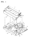
- Referring to Figure 1, the deck of the conventional magnetic recording/reproducing apparatus includes a
main chassis 10, asub chassis 20 slidably installed on themain chassis 10 and acassette housing 30 movably installed on thesub chassis 20, on which a tape cassette C is mounted. - A
head drum 11, aloading motor 12, acapstan motor 13 and a plurality ofguide rollers 14 andguide poles 15, constituting a tape running system are disposed on themain chassis 10. A pair of reel tables 21, 22 for driving the tape reels (not shown) of the tape cassette C are disposed on thesub chassis 20. - The
cassette housing 30 can be moved between a loaded position and an ejection position. The deck of the magnetic recording/reproducing apparatus includes a tape cassette ejecting apparatus 40 (see Figures 2A and 2B) for locking thecassette housing 30 on thesub chassis 20, when it is in the loaded position, and unlocking thecassette housing 30 and transferring it to the ejection position for ejection of the tape cassette C. - As illustrated in Figures 1, 2A and 2B, the tape
cassette ejecting apparatus 40 includes alocking lever 41, installed on thecassette housing 30, aneject lever 43, installed on thesub chassis 20, and acassette switch 45. - The
locking lever 41 has alocking protrusion 41 a and anunlocking protrusion 41b. When thecassette housing 30 is transferred to the loaded position, thelocking protrusion 41 a is received alocking slot 20a formed on thesub chassis 20. - The
eject lever 43 is installed on thesub chassis 20 for rotation by apin 42 back and forth through a predetermined angle. Theeject lever 43 includes anoperation portion 43a, contacting the unlockingprotrusion 41b of thelocking lever 41, apressing portion 43b and anelastic portion 43c. Awasher 44 for preventing separation of theeject lever 43 is coupled onto thepin 42. - A
cassette switch 45 is installed on one side of thesub chassis 20 for being opened and closed by the back and forth rotation of theeject lever 43. - In the tape
cassette ejecting apparatus 40, when thecassette housing 30, on which the tape cassette C has been mounted, is transferred to the loaded position, thelocking protrusion 41a of thelocking lever 41 of thecassette housing 30 is hooked in thelocking slot 20a of thesub chassis 20, thereby locking thecassette housing 30. The pressingportion 43b of theeject lever 43 presses a contact point of thecassette switch 45, to close thecassette switch 45. - When the user presses an eject button (not shown) to eject the tape cassette C, the
eject lever 43 is rotated in the anticlockwise direction, as viewed in the drawing (arrowed direction in Figure 2a) to push theunlocking protrusion 41b of thelocking lever 41, thereby freeing thelocking protrusion 41a. Accordingly, thecassette housing 30 is unlocked and transferred to the ejection position. Thecassette switch 45 is separated from thepressing portion 43b of theeject lever 43 and is thus opened. - However, this known tape cassette ejecting apparatus requires subsidiary components such as the
pin 42 for coupling theeject lever 43 to thechassis 20 and thewasher 44 for preventing separation of theeject lever 43, which inevitably increases the number of assembly components and the number of assembly process steps resulting in lower productivity and higher costs. - A tape cassette deck, according to the present invention, is characterised in that the pivot of the eject lever comprises a projection integrally formed with the chassis.
- The projection may be is a shaft.
- The eject lever is preferably clipped onto the projection. For example, the eject lever may comprise a hook member which extends through a hole in the chassis and engages the chassis to retain the eject lever on said projection.
- A switch may be included for detecting whether the cassette housing is in its loaded or tape ejection positions. This switch may be mounted on the opposite side of the chassis to the cassette holder and the eject lever may be configured for operating the switch.
- An embodiment of the present invention will now be described, by way of example, with reference to Figures 3 to 6 of the accompanying drawings, in which:
- Figure 1 is a schematic perspective view of a deck of a conventional magnetic recording/reproducing apparatus;
- Figure 2a and 2b are an exploded perspective view and an assembly cross-sectional view of the structure and operation of a tape cassette ejecting apparatus installed on the deck of Figure 1 respectively;
- Figure 3 is a perspective view of a deck of a magnetic recording/reproducing apparatus using a tape cassette ejecting apparatus according to the present invention;
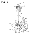
- Figure 4 is an exploded perspective view of the tape cassette ejecting apparatus in Figure 3;
- Figure 5 is an assembly cross-sectional view of Figure 4; and
- Figure 6 is a front view of an eject lever of the tape cassette ejecting apparatus in Figure 3.
-
- Referring to Figure 3, the
chassis 100 of a cassette deck has abase surface 101 and foursides base surface 101. Thechassis 100 houses and supports a pair of reel tables 110, 120 for rotating tape reels (not shown) of a tape cassette C, aloading motor 130, acapstan motor 140, a plurality ofguide rollers 150 andguide poles 160 constituting a tape running system, and ahead drum assembly 170. - The
cassette housing 200 is installed on thechassis 100 for movement between a loaded position and a tape ejection position by anX lever 400. The tape cassette C is mounted in thecassette housing 200. Therefore, the tape cassette C can be stably positioned on the reel tables 110, 120 of thechassis 100. - The tape
cassette ejecting apparatus 300 locks thecassette housing 200 on thechassis 100, when thecassette housing 200 is transferred to the loaded position, and unlocks thecassette housing 200 and transfers thecassette housing 200 to the ejection position for ejection the tape cassette C. - As shown in Figures 3 to 6, the tape
cassette ejecting apparatus 300 comprises, on thechassis 100, apin boss 101a, ahook hole 101b and alocking slot 102a which are formed in a single body, alocking lever 310, installed on thecassette housing 200, aneject lever 320, installed on thechassis 100, and acassette switch 330. - As depicted in Figures 4 and 5, the
pin boss 101a is incorporated in thechassis 100 by deep-drawing. Theeject lever 320 is rotatable back and forth around thepin boss 101a through a predetermined angle. Thehook hole 101b is formed on thechassis 100 adjacently to thepin boss 101a. Thelocking slot 102a is formed on oneside 102 of thechassis 100. Thehook hole 101b and thelocking slot 102a are explained below in more detail. - The
locking lever 310 has alocking protrusion 311 hooked in thelocking slot 102a when thecassette housing 200 is transferred to the loaded position and anunlocking protrusion 312, contacting theeject lever 320, which is explained below in more detail. Thelocking lever 310 is installed on thecassette housing 200 for rotation about anaxle 313 so that thelocking protrusion 311 can be elastically biased in the insertion direction into thelocking slot 102a by aspring 314. - As mentioned above, the
eject lever 320 is installed on thechassis 100 for rotation back and forth about thepin boss 101a through a predetermined angle. Theeject lever 320 comprises ahook portion 321, hooked in thehook hole 101b of thechassis 100 to prevent separation of thechassis 100. Therefore, theeject lever 320 can be coupled to thechassis 100 to be fully operated, without using subsidiary materials, such as a pin or a washer. - The
eject lever 320 comprises abody 322 having apin hole 322a for housing thepin boss 101a of thechassis 100, anoperation portion 323 and apressing portion 324. Theoperation portion 323 contacts theunlocking protrusion 312 of thelocking lever 310 and the pressingportion 324 controls acontact point 331 of thecassette switch 330 which is described below in more detail. In theeject lever 320 as shown in Figure 6, thepressing portion 324 is elastically formed on thebody 322. Even if an excessive external force is applied to theeject lever 320, thepressing portion 324 buffers the force and efficiently operates the contact point 331 (as shown in Figure 4) of thecassette switch 330. - As described above, the
cassette switch 330 is opened and closed by the back and forth rotation of theeject lever 320, for providing "locked" and "unlock" signals for thecassette housing 200 to a control portion (not shown). - Preferably, the
cassette switch 330 is installed on the bottom surface of thechassis 100 to efficiently use the inside space of thechassis 100. - In the tape cassette ejecting apparatus described above, when the cassette housing 200, on which the tape cassette C has been mounted, is moved to the loaded position, the
cassette housing 200 is locked. With thecassette housing 200 locked, in order to eject the tape cassette C, theeject lever 320 is rotated in the anticlockwise direction, as shown in Figure 4, thereby pushing the unlockingprotrusion 312 of thelocking lever 310. Thus, thecassette housing 200 is unlocked and moved to the tape ejection position. - The locking and unlocking operations of the
cassette housing 200 are performed in the same manner as those of the conventional apparatus. However, the tapecassette ejecting apparatus 300 can easily couple theeject lever 320 to thechassis 100 by using thepin boss 101a incorporated with thechassis 100 and thehook portion 321 formed on theeject lever 320, instead of being required to use subsidiary materials, such as a pin or a washer. - A number of assembly process steps can be reduced by decreasing a number of assembly components. That is, the process step for installing the pin on the chassis and a process for assembling the eject lever to the pin and coupling the washer onto the pin can be omitted.
- As discussed earlier, the tape cassette ejecting apparatus can couple the eject lever to the chassis to be rotated in the forward/backward directions though a predetermined angle, by using the pin boss formed on the chassis and the hook portion formed on the eject lever. That is, the tape cassette ejecting apparatus can reduce the number of the assembly components by omitting the subsidiary materials such as the pin or the washer, which results in lower costs and higher productivity.
Claims (16)
- A cassette tape deck comprising:characterised in that the pivot (101a) of the eject lever (320) comprises a projection integrally formed with the chassis (100).a chassis (100);a cassette housing (200) moveable between loaded and tape ejection positions;means (102a, 311) for retaining the cassette housing (200) in its loaded position; andan eject lever (320) for releasing the cassette housing (200) from its loaded position,
- A deck according to claim 1, wherein said projection (101a) is a shaft.
- A deck according to claim 1 or 2, wherein the eject lever (320) comprises a hook member (321) which extends through a hole (101b) in the chassis (100) and engages the chassis (100) to retain the eject lever (320) on said projection (101a).
- A deck according to claim 1, 2 or 3, including a switch (330) for detecting whether the cassette housing (200) is in its loaded or tape ejection positions,
wherein the switch (330) is mounted on the opposite side of the chassis (100) to the cassette holder (200) and the eject lever (320) is configured for operating the switch (330). - A cassette tape ejecting apparatus of a magnetic recording/reproducing apparatus, comprising:a chassis having a pin boss, a hook hole and a locking groove which are formed as a single body;a cassette housing installed on the chassis to be transferred to a tape insertion position and a tape ejection position, a cassette tape being mounted thereon;a locking lever being installed on the cassette housing, and having a locking protrusion hooked on the locking groove when the cassette housing is transferred to the tape insertion position; andan eject lever installed on the chassis to be rotated through the pin boss in the forward/backward direction at a predetermined angle, for unlocking the locking protrusion from the locking groove to eject the cassette tape.
- The apparatus as claimed in claim 5, comprising a cassette switch, which is turned on/off by the forward/backward rotation, respectively of the eject lever, for detecting the ejection of the cassette tape,
wherein the locking lever comprises an unlocking protrusion contacting the eject lever, and the eject lever comprises a body having a pin hole for housing the pin boss, an operation portion contacting the unlocking protrusion of the locking lever, and a pressing portion for operating the cassette switch. - The apparatus as claimed in claim 5, wherein the eject lever comprises a hook portion hooked on the hook hole of the chassis, for preventing separation.
- The apparatus as claimed in claim 5, wherein the pin boss is formed by deep-drawing.
- The apparatus as claimed in claim 6, wherein the pressing portion has elasticity to the body.
- The apparatus as claimed in claim 6, wherein the cassette switch is installed on the bottom surface of the chassis.
- A magnetic recording/reproducing apparatus comprising:wherein the cassette tape ejecting apparatus comprises:a chassis for supporting reel tables, a tape running system and a head drum;a cassette housing installed on the chassis to be transferred to a tape insertion position and a tape ejection position, a cassette tape being mounted thereon; anda cassette tape ejecting apparatus for locking the cassette housing on the chassis when the cassette housing is transferred to the tape insertion position, and unlocking the cassette housing and transferring the cassette housing to the tape ejection position to eject the cassette tape,a pin boss, a hook hole and a locking groove which are formed as a single body with the chassis;a locking lever being installed on the cassette housing, and having a locking protrusion hooked on the looking groove when the cassette housing is transferred to the tape insertion position, and an unlocking protrusion;an eject lever installed on the chassis to be rotated through the pin boss in the forward/backward direction at a predetermined angle, for unlocking the locking protrusion from the locking groove to eject the cassette tape; anda cassette switch turned on/off by the forward/backward rotation of the eject lever, for sensing ejection of the cassette tape.
- The apparatus as claimed in claim 11, wherein the eject lever comprises a body having a pin hole for housing the pin boss, an operation portion contacting the unlocking protrusion of the locking lever, and a pressing portion for operating the cassette switch.
- The apparatus as claimed in claim 12, wherein the eject lever comprises a hook portion hooked on the hook hole of the chassis, for preventing separation.
- The apparatus as claimed in claim 12, wherein the pin boss is formed by deep-drawing.
- The apparatus as claimed in claim 12, wherein the pressing portion has elasticity to the body.
- The apparatus as claimed in claim 12, wherein the cassette switch is installed on the bottom surface of the chassis.
Applications Claiming Priority (2)
| Application Number | Priority Date | Filing Date | Title |
|---|---|---|---|
| KR1020040045821A KR20050120462A (en) | 2004-06-19 | 2004-06-19 | Cassette tape ejecting apparatus and magnetic recording/reproducing apparatus having the same |
| KR2004045821 | 2004-06-19 |
Publications (2)
| Publication Number | Publication Date |
|---|---|
| EP1607960A2 true EP1607960A2 (en) | 2005-12-21 |
| EP1607960A3 EP1607960A3 (en) | 2007-01-03 |
Family
ID=34979830
Family Applications (1)
| Application Number | Title | Priority Date | Filing Date |
|---|---|---|---|
| EP05104304A Withdrawn EP1607960A3 (en) | 2004-06-19 | 2005-05-20 | Cassette tape eject mechanism |
Country Status (5)
| Country | Link |
|---|---|
| US (1) | US7312948B2 (en) |
| EP (1) | EP1607960A3 (en) |
| JP (1) | JP2006004602A (en) |
| KR (1) | KR20050120462A (en) |
| CN (1) | CN1710651A (en) |
Citations (1)
| Publication number | Priority date | Publication date | Assignee | Title |
|---|---|---|---|---|
| US20010012173A1 (en) | 2000-01-25 | 2001-08-09 | Kiyoshi Kumagai | Cassette loading apparatus |
Family Cites Families (9)
| Publication number | Priority date | Publication date | Assignee | Title |
|---|---|---|---|---|
| JPH0229968A (en) * | 1988-07-19 | 1990-01-31 | Sankyo Seiki Mfg Co Ltd | Tape cassette ejector |
| JPH02148456A (en) | 1988-11-30 | 1990-06-07 | Pioneer Electron Corp | Cassette eject device for tape player |
| US5233200A (en) | 1991-12-23 | 1993-08-03 | At&T Bell Laboratories | Method and apparatus for contactless monitoring of tension in a moving fiber |
| KR0136629Y1 (en) | 1992-11-04 | 1999-05-01 | 이헌조 | Cassette Housing Locking Device for Camcorders |
| US6038100A (en) * | 1994-08-06 | 2000-03-14 | Canon Kabushiki Kaisha | Recording and/or reproducing apparatus with variably damped cassette loading mechanism |
| KR200187925Y1 (en) | 1997-12-04 | 2000-07-15 | 구자홍 | Cassette ejector of magnetic recording player |
| JP3075806U (en) * | 2000-08-23 | 2001-03-06 | 船井電機株式会社 | Magnetic tape unit |
| JP3075807U (en) * | 2000-08-23 | 2001-03-06 | 船井電機株式会社 | Magnetic tape unit |
| KR100465166B1 (en) * | 2002-10-08 | 2005-01-13 | 삼성전자주식회사 | Locking device of tape cassette housing for tape recorder |
-
2004
- 2004-06-19 KR KR1020040045821A patent/KR20050120462A/en not_active Withdrawn
-
2005
- 2005-02-22 US US11/061,521 patent/US7312948B2/en not_active Expired - Fee Related
- 2005-05-20 EP EP05104304A patent/EP1607960A3/en not_active Withdrawn
- 2005-05-23 CN CNA2005100728113A patent/CN1710651A/en active Pending
- 2005-05-23 JP JP2005149721A patent/JP2006004602A/en active Pending
Patent Citations (1)
| Publication number | Priority date | Publication date | Assignee | Title |
|---|---|---|---|---|
| US20010012173A1 (en) | 2000-01-25 | 2001-08-09 | Kiyoshi Kumagai | Cassette loading apparatus |
Also Published As
| Publication number | Publication date |
|---|---|
| CN1710651A (en) | 2005-12-21 |
| US7312948B2 (en) | 2007-12-25 |
| KR20050120462A (en) | 2005-12-22 |
| US20050280930A1 (en) | 2005-12-22 |
| EP1607960A3 (en) | 2007-01-03 |
| JP2006004602A (en) | 2006-01-05 |
Similar Documents
| Publication | Publication Date | Title |
|---|---|---|
| NL8301144A (en) | OPERATING MODE FOR CHANGEOVER. | |
| JPH09223348A (en) | Disk unit | |
| EP1607960A2 (en) | Cassette tape eject mechanism | |
| US4704651A (en) | Cassette tape deck operating mechanism | |
| US5038236A (en) | Magnetic tape cassette ejecting device | |
| US6512656B1 (en) | Recording and/or reproducing apparatus for a magnetic tape | |
| JP3697911B2 (en) | Magnetic tape recording / reproducing device | |
| EP1548729B1 (en) | Stack type optical disk changer | |
| KR100207743B1 (en) | Tlub locking release apparatus of tape recorder | |
| JP3042767B2 (en) | Automotive tape recorder | |
| US7487518B2 (en) | Disk loading apparatus and method | |
| JPH056589Y2 (en) | ||
| KR100207706B1 (en) | Reel disk break device of tape recorder | |
| US7375919B2 (en) | Recording and reproducing apparatus | |
| JPH08171768A (en) | Cartridge changer | |
| KR830002732Y1 (en) | Tape recorder | |
| EP0376287A2 (en) | Cassette loading apparatus with single switch control | |
| JPH01144282A (en) | Pickup protection mechanism for optical disk driving device | |
| JPH0454590Y2 (en) | ||
| JPH0823955B2 (en) | Cassette mounting device | |
| JPS6125076Y2 (en) | ||
| JP2579378Y2 (en) | Recording medium transport device | |
| JPS6124052A (en) | Disc device | |
| JP2001052396A (en) | Magnetic recording / reproducing device | |
| JPH0212646A (en) | Recording or playback device |
Legal Events
| Date | Code | Title | Description |
|---|---|---|---|
| PUAI | Public reference made under article 153(3) epc to a published international application that has entered the european phase |
Free format text: ORIGINAL CODE: 0009012 |
|
| AK | Designated contracting states |
Kind code of ref document: A2 Designated state(s): AT BE BG CH CY CZ DE DK EE ES FI FR GB GR HU IE IS IT LI LT LU MC NL PL PT RO SE SI SK TR |
|
| AX | Request for extension of the european patent |
Extension state: AL BA HR LV MK YU |
|
| PUAL | Search report despatched |
Free format text: ORIGINAL CODE: 0009013 |
|
| AK | Designated contracting states |
Kind code of ref document: A3 Designated state(s): AT BE BG CH CY CZ DE DK EE ES FI FR GB GR HU IE IS IT LI LT LU MC NL PL PT RO SE SI SK TR |
|
| AX | Request for extension of the european patent |
Extension state: AL BA HR LV MK YU |
|
| 17P | Request for examination filed |
Effective date: 20070219 |
|
| AKX | Designation fees paid |
Designated state(s): DE GB NL |
|
| 17Q | First examination report despatched |
Effective date: 20071213 |
|
| GRAP | Despatch of communication of intention to grant a patent |
Free format text: ORIGINAL CODE: EPIDOSNIGR1 |
|
| STAA | Information on the status of an ep patent application or granted ep patent |
Free format text: STATUS: THE APPLICATION IS DEEMED TO BE WITHDRAWN |
|
| 18D | Application deemed to be withdrawn |
Effective date: 20090303 |