EP1607780B1 - Optical cable having an improved compression strength characteristic - Google Patents
Optical cable having an improved compression strength characteristic Download PDFInfo
- Publication number
- EP1607780B1 EP1607780B1 EP05011462A EP05011462A EP1607780B1 EP 1607780 B1 EP1607780 B1 EP 1607780B1 EP 05011462 A EP05011462 A EP 05011462A EP 05011462 A EP05011462 A EP 05011462A EP 1607780 B1 EP1607780 B1 EP 1607780B1
- Authority
- EP
- European Patent Office
- Prior art keywords
- optical cable
- tension member
- central tension
- tube
- optical
- Prior art date
- Legal status (The legal status is an assumption and is not a legal conclusion. Google has not performed a legal analysis and makes no representation as to the accuracy of the status listed.)
- Expired - Lifetime
Links
Images


Classifications
-
- G—PHYSICS
- G02—OPTICS
- G02B—OPTICAL ELEMENTS, SYSTEMS OR APPARATUS
- G02B6/00—Light guides; Structural details of arrangements comprising light guides and other optical elements, e.g. couplings
- G02B6/44—Mechanical structures for providing tensile strength and external protection for fibres, e.g. optical transmission cables
- G02B6/4401—Optical cables
- G02B6/4429—Means specially adapted for strengthening or protecting the cables
-
- G—PHYSICS
- G02—OPTICS
- G02B—OPTICAL ELEMENTS, SYSTEMS OR APPARATUS
- G02B6/00—Light guides; Structural details of arrangements comprising light guides and other optical elements, e.g. couplings
- G02B6/44—Mechanical structures for providing tensile strength and external protection for fibres, e.g. optical transmission cables
- G02B6/4401—Optical cables
- G02B6/4429—Means specially adapted for strengthening or protecting the cables
- G02B6/44384—Means specially adapted for strengthening or protecting the cables the means comprising water blocking or hydrophobic materials
-
- B—PERFORMING OPERATIONS; TRANSPORTING
- B05—SPRAYING OR ATOMISING IN GENERAL; APPLYING FLUENT MATERIALS TO SURFACES, IN GENERAL
- B05D—PROCESSES FOR APPLYING FLUENT MATERIALS TO SURFACES, IN GENERAL
- B05D3/00—Pretreatment of surfaces to which liquids or other fluent materials are to be applied; After-treatment of applied coatings, e.g. intermediate treating of an applied coating preparatory to subsequent applications of liquids or other fluent materials
- B05D3/06—Pretreatment of surfaces to which liquids or other fluent materials are to be applied; After-treatment of applied coatings, e.g. intermediate treating of an applied coating preparatory to subsequent applications of liquids or other fluent materials by exposure to radiation
- B05D3/061—Pretreatment of surfaces to which liquids or other fluent materials are to be applied; After-treatment of applied coatings, e.g. intermediate treating of an applied coating preparatory to subsequent applications of liquids or other fluent materials by exposure to radiation using U.V.
- B05D3/065—After-treatment
- B05D3/067—Curing or cross-linking the coating
-
- G—PHYSICS
- G02—OPTICS
- G02B—OPTICAL ELEMENTS, SYSTEMS OR APPARATUS
- G02B1/00—Optical elements characterised by the material of which they are made; Optical coatings for optical elements
- G02B1/10—Optical coatings produced by application to, or surface treatment of, optical elements
- G02B1/14—Protective coatings, e.g. hard coatings
-
- G—PHYSICS
- G02—OPTICS
- G02B—OPTICAL ELEMENTS, SYSTEMS OR APPARATUS
- G02B6/00—Light guides; Structural details of arrangements comprising light guides and other optical elements, e.g. couplings
- G02B6/44—Mechanical structures for providing tensile strength and external protection for fibres, e.g. optical transmission cables
- G02B6/4401—Optical cables
- G02B6/4429—Means specially adapted for strengthening or protecting the cables
- G02B6/4434—Central member to take up tensile loads
-
- H—ELECTRICITY
- H01—ELECTRIC ELEMENTS
- H01B—CABLES; CONDUCTORS; INSULATORS; SELECTION OF MATERIALS FOR THEIR CONDUCTIVE, INSULATING OR DIELECTRIC PROPERTIES
- H01B11/00—Communication cables or conductors
- H01B11/22—Cables including at least one electrical conductor together with optical fibres
Definitions
- the present invention relates to an optical cable, and more particularly to an optical cable having an improved compression strength characteristic as compared to conventional optical cables.
- optical cables may be classified according to the installation method of the optical cable. For example, duct line optical cables are installed in ducts that have been buried in the ground; buried optical cables are directly buried in the ground; and aerial optical cables are installed in the air using poles.
- FIG. 1 shows a typical buried optical cable.
- the optical cable 100 includes a central tension member 110, a plurality of tubes 140, a binder 150, a first sheath 160, a tension member 170, and a second sheath 180.
- the central tension member 110 is positioned in the center of the optical cable 100. It may be a rod type member having a circular sectional shape. It provides the optical cable 100 with tensile strength.
- the tubes 140 are positioned around the central tension member 110. They are oriented parallel to the central tension member 110 and have a hole in the center thereof. A plurality of optical fibers 120 is positioned in the hole of the tubes 140. The space within the tubes 140 is filled with jelly 130. The jelly 130 absorbs moisture that has penetrated into the tubes 140.
- the binder 150 is positioned around the plurality of tubes 140. It is of a tape type and surrounds the tubes 140 to hold them.
- the first sheath 160 is positioned around the tubes by an extrusion process.
- the tension member 170 is positioned around the first sheath 160. It may be helically wound around the first sheath 160.
- the tension member 170 provides the optical cable 100 with tensile strength and may include a number of aramid yarns.
- the second sheath 180 is positioned around the tension member 170 by an extrusion process.
- the conduct line optical cable and the buried optical cable have low compression strength and cannot be installed on the ground while being directly exposed to external environment.
- an optical cable that has improved compression strength and can be installed on the ground, e.g., on the ballasts near railroads.
- Such an optical cable must be able to withstand a certain loads, e.g., a load from a track vehicle for railroad maintenance.
- one aspect of the present relates to an optical cable having improved compression strength so that it can be directly installed on the ground.
- One embodiment of the present invention is directed to an optical cable comprising: a central tension member positioned in the center of the optical cable and having at least one groove; at least one metal tube seated in the groove and containing at least one optical fiber; a strength member positioned around the central tension member and the tube; a sheath positioned around the strength member and a j elly is applied on an outer peripheral surface of the strength member so that the strength member does not adhere to the sheath.
- the optical cable 200 includes a central tension member 210, first and second tubes 240 and 245, a binder 250, a strength member 260, and a sheath 270.
- the central tension member 210 is substantially positioned in the center of the optical cable 200.
- the central tension member 210 has first and second grooves 212 and 214 that may be positioned symmetrically about the central axis of the optical cable 200. It is noted that other positions for the grooves are possible.
- the central tension member 210 may be made of metallic material, e.g., an aluminum material. It is noted that other non-metallic materials are possible that provide similar strength characteristics.
- the central tension member 210 provides the optical cable 200 with tensile strength.
- the central tension member 210 may be twisted in clockwise direction, in counterclockwise direction, or in a combination thereof (i.e., a portion of the central tension member is twisted in clockwise direction and another portion thereof in counterclockwise, and these portions intersect) about the central axis thereof (i.e., the central axis of the optical cable).
- the first and second grooves 212 and 214 are wound about the central axis helically or in S-Z mode.
- the central tension member 210 which is made of materials noted above, can withstand an improved compression load as compared to conventional members.
- the central tension member 210 maintains the linearity of the optical cable 200. It may also provide flame retardancy.
- the central tension member 210 has an outer diameter of 7.54 mm.
- the S-Z mode is disclosed in U.S. Patent No. 4,828,352 of Heinrich A. Kraft , entitled "S-Z stranded optical cable” (the contents of which are hereby incorporated by reference), and detailed description thereof will be omitted.
- the first and second grooves 212 and 214 have a depth that is smaller than the diameter of the tubes 240 and 245 and a width that is larger than the diameter of the tubes 240 and 245. This is for the purpose of minimizing the influence of deformation of the tubes 240 and 245, due to external impact, by giving the first and second grooves 212 and 214 a concave shape.
- the first and second tubes 240 and 245 are seated within the first and second grooves 212 and 214 and are twisted around the central tension member 210 helically or in S-Z mode.
- the tubes 240 and 245 may have the shape of a hollow cylinder. It is noted that other shapes are possible, e.g., a hollow oval.
- a plurality of optical fibers 220 and 225 is contained in the hole of the tubes 240 and 245.
- the space within the tubes 240 and 245 is filled with jelly 230 and 235 for absorbing the moisture that has penetrated into the tubes 240 and 245.
- the first and second tubes 240 and 245 are made of metallic material, e.g., a steel material. It is noted that other non-metallic materials are possible that provide similar strength characteristics.
- the tubes 240 and 245 have an outer diameter of 2.5 mm.
- the binder 250 surrounds the central tension member 210 and the first and second tubes 240 and 245.
- the grooves 212 and 214, which are sealed by the binder 250, may be filled with UV-curable material and then cured by UV irradiation.
- the binder 250 includes a waterproof tape, which prevents moisture from penetrating into the interior thereof.
- the strength member 260 which is positioned around the binder 250, provides the optical cable 200 with improved compression strength as compared to conventional members.
- the strength member 260 is made of metallic material, e.g., a steel material. It is noted that other non-metallic materials are possible that provide similar strength characteristics.
- the strength member 260 may be wound helically around the binder 250. Jelly is applied on the outer peripheral surface of the strength member 260 so that the strength member 260 does not adhere to the sheath 270. This makes it easy to peel the sheath 270 off.
- the strength member 260 includes a number of steel rods, and jelly is applied on the outer peripheral surface of the steel rods. In one embodiment, the steel rods have an outer diameter of 2.55 mm.
- the sheath 270 may be positioned around the strength member 260 by an extrusion process.
- the sheath 270 prevents the danger of electric shock by insulating the strength member 260, when it is made of a metallic material, from electric contact.
- the sheath 270 provides high compression strength.
- the sheath 270 is made of plastic material, preferably of flame retardant material. When the sheath 270 is made of flame retardant material, it prevents a fire from spreading.
- the flame retardant material may be formed of a substance, such as PE (polyethylene) and EVA (ethylene vinylacetate copolymer), and an additive, such as aluminum oxide and magnesium oxide.
- an optical cable 310 is interposed between upper and lower steel plates 320 and 330, and a load is applied to the upper steel plate 330.
- the optical cable 310 has at least one optical fiber mounted thereon.
- An optical signal is input to an end of the optical fiber, and an optical loss is measured from the optical signal, which is output from the other end of the optical fiber.
- the upper and lower steel plates 320 and 330 have an area of 100 x 100 mm 2 .
- FIG. 4 shows a compression strength curve 410 of a typical duct line optical cable, a compression strength curve 420 of a typical buried optical cable, and a compression strength curve 430 of the optical cable 200 shown in FIG. 2 .
- the optical cable 200 has an improved compression strength compared with typical optical cables.
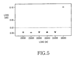
- FIG. 5 the compression strength of the optical cable shown in FIG. 2 is illustrated in detail.
- a compression strength test is performed as disclosed with reference to FIG. 3 .
- Each target load (20,000, 25,000,..., 38,000N) is maintained for one minute while an optical loss is measured.
- the jelly 230 and 235 and the optical fibers 220 and 225 within the tubes 240 and 245 of the optical cable 200 have not been damaged at all, but the jelly 130 and the optical fiber 120 within the tube 140 of the typical buried optical cable 100 have been damaged.
Landscapes
- Physics & Mathematics (AREA)
- General Physics & Mathematics (AREA)
- Optics & Photonics (AREA)
- Engineering & Computer Science (AREA)
- Plasma & Fusion (AREA)
- Communication Cables (AREA)
Description
- The present invention relates to an optical cable, and more particularly to an optical cable having an improved compression strength characteristic as compared to conventional optical cables.
- Conventional optical cables may be classified according to the installation method of the optical cable. For example, duct line optical cables are installed in ducts that have been buried in the ground; buried optical cables are directly buried in the ground; and aerial optical cables are installed in the air using poles.
-
FIG. 1 shows a typical buried optical cable. Theoptical cable 100 includes acentral tension member 110, a plurality oftubes 140, abinder 150, afirst sheath 160, atension member 170, and asecond sheath 180. - The
central tension member 110 is positioned in the center of theoptical cable 100. It may be a rod type member having a circular sectional shape. It provides theoptical cable 100 with tensile strength. - The
tubes 140 are positioned around thecentral tension member 110. They are oriented parallel to thecentral tension member 110 and have a hole in the center thereof. A plurality ofoptical fibers 120 is positioned in the hole of thetubes 140. The space within thetubes 140 is filled withjelly 130. Thejelly 130 absorbs moisture that has penetrated into thetubes 140. - The
binder 150 is positioned around the plurality oftubes 140. It is of a tape type and surrounds thetubes 140 to hold them. - The
first sheath 160 is positioned around the tubes by an extrusion process. - The
tension member 170 is positioned around thefirst sheath 160. It may be helically wound around thefirst sheath 160. Thetension member 170 provides theoptical cable 100 with tensile strength and may include a number of aramid yarns. - The
second sheath 180 is positioned around thetension member 170 by an extrusion process. - Use of such a typical buried
optical cable 100 requires that a trench be dug in the ground for installation, which is a costly procedure considering both time and money. In the case of using a duct line optical cable, the ground must also be dug before installing conduct lines. - The conduct line optical cable and the buried optical cable have low compression strength and cannot be installed on the ground while being directly exposed to external environment.
- Accordingly, there is a need in the art for an optical cable that has improved compression strength and can be installed on the ground, e.g., on the ballasts near railroads. Such an optical cable must be able to withstand a certain loads, e.g., a load from a track vehicle for railroad maintenance.
- Accordingly, one aspect of the present relates to an optical cable having improved compression strength so that it can be directly installed on the ground.
- One embodiment of the present invention is directed to an optical cable comprising: a central tension member positioned in the center of the optical cable and having at least one groove; at least one metal tube seated in the groove and containing at least one optical fiber; a strength member positioned around the central tension member and the tube; a sheath positioned around the strength member and a j elly is applied on an outer peripheral surface of the strength member so that the strength member does not adhere to the sheath.
- The above and other aspects, features and embodiments of the present invention will be more apparent from the following detailed description taken in conjunction with the accompanying drawings, in which:
-
FIG. 1 shows a typical buried optical cable; -
FIG. 2 shows an optical cable according to one embodiment of the present invention; -
FIG. 3 illustrates a method for testing the compression strength of optical cables; -
FIG. 4 shows the comparison in compression strength between the optical cable shown inFIG. 2 and typical optical cables; and -
FIG. 5 shows in detail the compression strength of the optical cable shown inFIG. 2 . - Hereinafter, embodiments of the present invention will be described with reference to the accompanying drawings. For the purposes of clarity and simplicity, a detailed description of known functions and configurations incorporated herein will be omitted as it may make the subject matter of the present invention unclear.
- Referring to
FIG. 2 , an optical cable according to one embodiment of the present invention is shown. Theoptical cable 200 includes acentral tension member 210, first andsecond tubes binder 250, astrength member 260, and asheath 270. - The
central tension member 210 is substantially positioned in the center of theoptical cable 200. Thecentral tension member 210 has first andsecond grooves optical cable 200. It is noted that other positions for the grooves are possible. Thecentral tension member 210 may be made of metallic material, e.g., an aluminum material. It is noted that other non-metallic materials are possible that provide similar strength characteristics. Thecentral tension member 210 provides theoptical cable 200 with tensile strength. - In various embodiments, the
central tension member 210 may be twisted in clockwise direction, in counterclockwise direction, or in a combination thereof (i.e., a portion of the central tension member is twisted in clockwise direction and another portion thereof in counterclockwise, and these portions intersect) about the central axis thereof (i.e., the central axis of the optical cable). As a result, the first andsecond grooves central tension member 210, which is made of materials noted above, can withstand an improved compression load as compared to conventional members. Thecentral tension member 210 maintains the linearity of theoptical cable 200. It may also provide flame retardancy. In one embodiment, thecentral tension member 210 has an outer diameter of 7.54 mm. The S-Z mode is disclosed inU.S. Patent No. 4,828,352 of Heinrich A. Kraft , entitled "S-Z stranded optical cable" (the contents of which are hereby incorporated by reference), and detailed description thereof will be omitted. - The first and
second grooves tubes tubes tubes second grooves 212 and 214 a concave shape. - The first and
second tubes second grooves central tension member 210 helically or in S-Z mode. Thetubes optical fibers tubes tubes jelly tubes second tubes tubes optical cable 200. Accordingly, theoptical fibers tubes tubes - The
binder 250 surrounds thecentral tension member 210 and the first andsecond tubes grooves binder 250, may be filled with UV-curable material and then cured by UV irradiation. Thebinder 250 includes a waterproof tape, which prevents moisture from penetrating into the interior thereof. - The
strength member 260, which is positioned around thebinder 250, provides theoptical cable 200 with improved compression strength as compared to conventional members. Thestrength member 260 is made of metallic material, e.g., a steel material. It is noted that other non-metallic materials are possible that provide similar strength characteristics. Thestrength member 260 may be wound helically around thebinder 250. Jelly is applied on the outer peripheral surface of thestrength member 260 so that thestrength member 260 does not adhere to thesheath 270. This makes it easy to peel thesheath 270 off. Thestrength member 260 includes a number of steel rods, and jelly is applied on the outer peripheral surface of the steel rods. In one embodiment, the steel rods have an outer diameter of 2.55 mm. - The
sheath 270 may be positioned around thestrength member 260 by an extrusion process. Thesheath 270 prevents the danger of electric shock by insulating thestrength member 260, when it is made of a metallic material, from electric contact. Thesheath 270 provides high compression strength. Thesheath 270 is made of plastic material, preferably of flame retardant material. When thesheath 270 is made of flame retardant material, it prevents a fire from spreading. For example, the flame retardant material may be formed of a substance, such as PE (polyethylene) and EVA (ethylene vinylacetate copolymer), and an additive, such as aluminum oxide and magnesium oxide. - Referring to
FIG. 3 , a method for testing the compression strength of optical cables is illustrated. In this method, anoptical cable 310 is interposed between upper andlower steel plates upper steel plate 330. Theoptical cable 310 has at least one optical fiber mounted thereon. An optical signal is input to an end of the optical fiber, and an optical loss is measured from the optical signal, which is output from the other end of the optical fiber. The upper andlower steel plates - Referring to
FIG. 4 , the comparison in compression strength between the optical cable shown inFIG. 2 and typical optical cables is illustrated. A compression strength test is performed as disclosed with reference toFIG. 3 . According to general international standards regarding the compression strength of optical cables, a crush load, which corresponds to a reference optical loss of 0.02dB, is indicated as compression strength.FIG. 4 shows acompression strength curve 410 of a typical duct line optical cable, acompression strength curve 420 of a typical buried optical cable, and acompression strength curve 430 of theoptical cable 200 shown inFIG. 2 . As shown, it is clear that theoptical cable 200 has an improved compression strength compared with typical optical cables. - Referring to
FIG. 5 , the compression strength of the optical cable shown inFIG. 2 is illustrated in detail. A compression strength test is performed as disclosed with reference toFIG. 3 . Each target load (20,000, 25,000,..., 38,000N) is maintained for one minute while an optical loss is measured. - As a result of performing a fire test on the
optical cable 200 shown inFIG. 2 and theoptical cable 100 shown inFIG, 1 , thejelly optical fibers tubes optical cable 200 have not been damaged at all, but thejelly 130 and theoptical fiber 120 within thetube 140 of the typical buriedoptical cable 100 have been damaged. - While the invention has been shown and described with reference to certain embodiments thereof, it will be understood by those skilled in the art that various changes in form and details may be made therein without departing from the scope of the invention as defined by the appended claims.
Claims (12)
- An optical cable (200) comprising:a central tension member (210) substantially positioned at the center of the optical cable, and the central tension member having at least one groove (212, 214) formed therein;at least one tube (240, 245) seated in the groove and containing at least one optical fiber (220, 225), wherein the central tension member being formed to at least partially surround the at least one tube;a strength member (260) positioned around the central tension member and the at least one tube; anda sheath (270) positioned around the strength member, characterized in that jelly is applied on an outer peripheral surface of the strength member so that the strength member does not adhere to the sheath.
- The optical cable as claimed in claim 1 further comprising a binder (250) interposed between the central tension member (210) and the strength member (260), as well as between the at least one tube (240, 245) and the strength member (260), to surround the central tension member and the at least one tube.
- The optical cable as claimed in claim 2, wherein the binder (250) includes a waterproof tape.
- The optical cable as claimed in claim 1, wherein the at least one groove (212, 214) of the central tension member (210) is filled with UV-curable material.
- The optical cable as claimed in claim 1, wherein the interior of the at least one tube (240, 245) is filled with jelly (230, 235).
- The optical cable as claimed in claim 1, wherein the central tension member (210), the at least one tube (240, 245), and the strength member (260) are made of metallic materials.
- The optical cable as claimed in claim 6, wherein the central tension member is made of aluminum material.
- The optical cable as claimed in claim 6, wherein the at least one tube and the strength member (210) are made of steel material.
- The optical cable as claimed in claim 6, wherein the strength member (260) includes a number of steel rods, and jelly is applied on the outer peripheral surface of the steel rods.
- The optical cable as claimed in claim 1, wherein the central tension member (210) has a plurality of grooves (212, 214) positioned symmetrically about the central axis thereof, the optical cable has a plurality of metal tubes (240, 245), and each of the at least one tubes is seated in each of the grooves.
- The optical cable as claimed in claim 1, wherein the at least one groove (212, 214) has a depth which is smaller than the diameter of the at least one tube (240, 245) and a width which is larger than the diameter of the at least one tube.
- The optical cable as claimed in claim 1, wherein the optical cable has an optical loss equal to or less than 0.02dB when a load of 35,000N is applied to the optical cable for one minute.
Applications Claiming Priority (2)
| Application Number | Priority Date | Filing Date | Title |
|---|---|---|---|
| KR1020040040404A KR100617746B1 (en) | 2004-06-03 | 2004-06-03 | Optical cable with high compressive strength |
| KR2004040404 | 2004-06-03 |
Publications (2)
| Publication Number | Publication Date |
|---|---|
| EP1607780A1 EP1607780A1 (en) | 2005-12-21 |
| EP1607780B1 true EP1607780B1 (en) | 2012-12-26 |
Family
ID=35004149
Family Applications (1)
| Application Number | Title | Priority Date | Filing Date |
|---|---|---|---|
| EP05011462A Expired - Lifetime EP1607780B1 (en) | 2004-06-03 | 2005-05-27 | Optical cable having an improved compression strength characteristic |
Country Status (4)
| Country | Link |
|---|---|
| US (1) | US7177508B2 (en) |
| EP (1) | EP1607780B1 (en) |
| KR (1) | KR100617746B1 (en) |
| CN (1) | CN100397130C (en) |
Cited By (1)
| Publication number | Priority date | Publication date | Assignee | Title |
|---|---|---|---|---|
| WO2018231675A1 (en) | 2017-06-12 | 2018-12-20 | Corning Research & Development Corporation | In-road interface protected cable |
Families Citing this family (3)
| Publication number | Priority date | Publication date | Assignee | Title |
|---|---|---|---|---|
| US8885999B2 (en) | 2010-03-19 | 2014-11-11 | Corning Cable Systems Llc | Optical USB cable with controlled fiber positioning |
| EP2416196A1 (en) * | 2010-08-02 | 2012-02-08 | British Telecommunications public limited company | Optical fibre securing device |
| CN104123987A (en) * | 2014-07-17 | 2014-10-29 | 安徽易奇软件科技有限公司 | Novel cable |
Family Cites Families (12)
| Publication number | Priority date | Publication date | Assignee | Title |
|---|---|---|---|---|
| CA2004470A1 (en) * | 1988-12-01 | 1990-06-01 | Paul Frederick Wettengel | Drop cable |
| KR100207818B1 (en) * | 1995-11-27 | 1999-07-15 | 윤종용 | Structure and manufacturing method of optical fiber composite processing wire using loose tube |
| US5651082A (en) * | 1996-06-17 | 1997-07-22 | Siecor Corporation | Optical ribbon cables and stranding method |
| US5822484A (en) * | 1996-06-21 | 1998-10-13 | Lucent Technologies Inc. | Lightweight optical groundwire |
| KR100217717B1 (en) * | 1996-09-16 | 1999-09-01 | 윤종용 | Optical cable |
| DE19811772A1 (en) * | 1998-03-18 | 1999-09-23 | Cit Alcatel | Flame retardant optical cable |
| US6584251B1 (en) * | 2000-05-23 | 2003-06-24 | Alcatel | Solid stranding flextube unit |
| US6671441B1 (en) * | 2000-08-22 | 2003-12-30 | Fitel Usa Corp. | Optical cabling apparatus having improved dry filling compound and method for making |
| KR20030034570A (en) * | 2001-10-26 | 2003-05-09 | 주식회사 머큐리 | Ribbon-tubed optical cable |
| US7184365B2 (en) * | 2002-12-26 | 2007-02-27 | Pgs Americas, Inc. | Unitary multi-cable towing system |
| US7421169B2 (en) * | 2003-06-20 | 2008-09-02 | Fujikura Ltd. | Optical fiber cable |
| US7095930B2 (en) * | 2003-07-17 | 2006-08-22 | Draka Comteq B.V. | Groove cable |
-
2004
- 2004-06-03 KR KR1020040040404A patent/KR100617746B1/en not_active Expired - Fee Related
- 2004-11-18 US US10/991,613 patent/US7177508B2/en not_active Expired - Lifetime
- 2004-12-22 CN CNB2004101020719A patent/CN100397130C/en not_active Expired - Fee Related
-
2005
- 2005-05-27 EP EP05011462A patent/EP1607780B1/en not_active Expired - Lifetime
Cited By (1)
| Publication number | Priority date | Publication date | Assignee | Title |
|---|---|---|---|---|
| WO2018231675A1 (en) | 2017-06-12 | 2018-12-20 | Corning Research & Development Corporation | In-road interface protected cable |
Also Published As
| Publication number | Publication date |
|---|---|
| CN100397130C (en) | 2008-06-25 |
| KR20050115111A (en) | 2005-12-07 |
| KR100617746B1 (en) | 2006-08-28 |
| CN1704785A (en) | 2005-12-07 |
| EP1607780A1 (en) | 2005-12-21 |
| US7177508B2 (en) | 2007-02-13 |
| US20050271337A1 (en) | 2005-12-08 |
Similar Documents
| Publication | Publication Date | Title |
|---|---|---|
| CA2338142C (en) | Hybrid electrical-optical cable for overhead installations | |
| US7242831B2 (en) | Low strain optical fiber cable | |
| US5131064A (en) | Cable having lightning protective sheath system | |
| DE3876176T2 (en) | COMBINING SERVICE AND COMMUNICATION DISTRIBUTION BODIES. | |
| US7218821B2 (en) | Optical fiber cables | |
| EP2075605A1 (en) | Optical cable | |
| US6836603B1 (en) | Optical fiber cables | |
| WO1996023239A3 (en) | Polypropylene-polyethylene copolymer buffer tubes for optical fiber cables and method for making the same | |
| KR20210081956A (en) | Marine cable | |
| KR102941747B1 (en) | Optical cable | |
| US9323019B1 (en) | Long span all dielectric self-supporting (ADSS) fiber optic cable | |
| US20140140670A1 (en) | Small-diameter high bending-resistance fiber optic cable | |
| US7177508B2 (en) | Optical cable having an improved compression strength characteristic | |
| EP1343040A2 (en) | Compact lightweight optical cable with pad | |
| US10048459B2 (en) | Optical broadband node cable | |
| EP4276508A1 (en) | Hybrid drop cable | |
| EP3213134B1 (en) | Self-supporting overhead telecommunication/power cable | |
| KR20240102408A (en) | Cable capable of motion detection and system for detecting motion of the same | |
| CN211628723U (en) | Power cable for large mechanical engine | |
| CN222530062U (en) | An irradiated low-smoke halogen-free flame-retardant compression-resistant cable | |
| EP3614187A1 (en) | Hybrid round cable | |
| CN220872723U (en) | High flame retardant buried loose sleeve layer stranded optical cable | |
| US6141473A (en) | Optical fiber composite ground wire | |
| KR20060059288A (en) | Slotted optical cable with high compressive strength | |
| RU2784837C1 (en) | Lightning protection cable with integrated fiber-optic communication cable (options) |
Legal Events
| Date | Code | Title | Description |
|---|---|---|---|
| PUAI | Public reference made under article 153(3) epc to a published international application that has entered the european phase |
Free format text: ORIGINAL CODE: 0009012 |
|
| 17P | Request for examination filed |
Effective date: 20050527 |
|
| AK | Designated contracting states |
Kind code of ref document: A1 Designated state(s): AT BE BG CH CY CZ DE DK EE ES FI FR GB GR HU IE IS IT LI LT LU MC NL PL PT RO SE SI SK TR |
|
| AX | Request for extension of the european patent |
Extension state: AL BA HR LV MK YU |
|
| AKX | Designation fees paid |
Designated state(s): DE FR |
|
| 17Q | First examination report despatched |
Effective date: 20100428 |
|
| GRAP | Despatch of communication of intention to grant a patent |
Free format text: ORIGINAL CODE: EPIDOSNIGR1 |
|
| RAP1 | Party data changed (applicant data changed or rights of an application transferred) |
Owner name: SAMSUNG ELECTRONICS CO., LTD. |
|
| GRAS | Grant fee paid |
Free format text: ORIGINAL CODE: EPIDOSNIGR3 |
|
| GRAA | (expected) grant |
Free format text: ORIGINAL CODE: 0009210 |
|
| AK | Designated contracting states |
Kind code of ref document: B1 Designated state(s): DE FR |
|
| REG | Reference to a national code |
Ref country code: DE Ref legal event code: R096 Ref document number: 602005037560 Country of ref document: DE Effective date: 20130228 |
|
| PLBE | No opposition filed within time limit |
Free format text: ORIGINAL CODE: 0009261 |
|
| STAA | Information on the status of an ep patent application or granted ep patent |
Free format text: STATUS: NO OPPOSITION FILED WITHIN TIME LIMIT |
|
| 26N | No opposition filed |
Effective date: 20130927 |
|
| REG | Reference to a national code |
Ref country code: DE Ref legal event code: R097 Ref document number: 602005037560 Country of ref document: DE Effective date: 20130927 |
|
| REG | Reference to a national code |
Ref country code: FR Ref legal event code: PLFP Year of fee payment: 12 |
|
| REG | Reference to a national code |
Ref country code: FR Ref legal event code: PLFP Year of fee payment: 13 |
|
| PGFP | Annual fee paid to national office [announced via postgrant information from national office to epo] |
Ref country code: DE Payment date: 20170530 Year of fee payment: 13 Ref country code: FR Payment date: 20170525 Year of fee payment: 13 |
|
| REG | Reference to a national code |
Ref country code: DE Ref legal event code: R119 Ref document number: 602005037560 Country of ref document: DE |
|
| PG25 | Lapsed in a contracting state [announced via postgrant information from national office to epo] |
Ref country code: DE Free format text: LAPSE BECAUSE OF NON-PAYMENT OF DUE FEES Effective date: 20181201 Ref country code: FR Free format text: LAPSE BECAUSE OF NON-PAYMENT OF DUE FEES Effective date: 20180531 |