EP1607656A2 - Chain - Google Patents
Chain Download PDFInfo
- Publication number
- EP1607656A2 EP1607656A2 EP05007770A EP05007770A EP1607656A2 EP 1607656 A2 EP1607656 A2 EP 1607656A2 EP 05007770 A EP05007770 A EP 05007770A EP 05007770 A EP05007770 A EP 05007770A EP 1607656 A2 EP1607656 A2 EP 1607656A2
- Authority
- EP
- European Patent Office
- Prior art keywords
- pin
- caulked
- pair
- hollow cylindrical
- end portions
- Prior art date
- Legal status (The legal status is an assumption and is not a legal conclusion. Google has not performed a legal analysis and makes no representation as to the accuracy of the status listed.)
- Granted
Links
Images


Classifications
-
- F—MECHANICAL ENGINEERING; LIGHTING; HEATING; WEAPONS; BLASTING
- F16—ENGINEERING ELEMENTS AND UNITS; GENERAL MEASURES FOR PRODUCING AND MAINTAINING EFFECTIVE FUNCTIONING OF MACHINES OR INSTALLATIONS; THERMAL INSULATION IN GENERAL
- F16G—BELTS, CABLES, OR ROPES, PREDOMINANTLY USED FOR DRIVING PURPOSES; CHAINS; FITTINGS PREDOMINANTLY USED THEREFOR
- F16G13/00—Chains
- F16G13/02—Driving-chains
- F16G13/06—Driving-chains with links connected by parallel driving-pins with or without rollers so-called open links
-
- B—PERFORMING OPERATIONS; TRANSPORTING
- B21—MECHANICAL METAL-WORKING WITHOUT ESSENTIALLY REMOVING MATERIAL; PUNCHING METAL
- B21L—MAKING METAL CHAINS
- B21L9/00—Making chains or chain links, the links being composed of two or more different parts, e.g. drive chains
- B21L9/02—Making chains or chain links, the links being composed of two or more different parts, e.g. drive chains of roller-chain or other plate-link type
- B21L9/06—Sorting, feeding, assembling, riveting, or finishing parts of chains
- B21L9/065—Assembling or disassembling
Definitions
- the present invention relates to a chain in which an inner link farmed by press-fitting both end portions of a pair of bushes into bush press-fitting holes of a pair of inner plates and an outer link formed by press-fitting both end portions of a pair of pins into pin press-fitting holes of a pair of outer plates are connected to each other by said pins, which penetrate through said bushes and protruded end portions of said pin are caulked.
- Patent Reference 1 Japanese Laid-open Patent Publication No. 2003-294090.
- One method comprises caulking protruded both end portions of a hardness-reduced pin by subjecting the both end portions of the pin to previous annealing treatment. Since in this method the caulked portions of the pin are not hard, the pin can be pulled out through the inner surface of a bush by a punch even while the pin being caulked.
- the other method uses a pin previously subjected to copper plating on end portions of the pin and comprises caulking protruded both end portions of the pin. Since in this method the caulked portions of the pin are not hard, the pin can also be pulled out through the inner surface of a bush by a punch even while the pin being caulked.
- the above-mentioned two methods have the following problems respectively. Namely, since the above-mentioned one method comprises an annealing step it increases in cost. Further, since the caulking width is large, the pressing load during caulking is increased. On the other hand, since the other method comprises performing copper plating and removing the plating material, it not only increases in cost but also must care for environmental contamination. Further, since the caulking width is large, the pressing load during caulking is increased.
- the object of the present invention is to provide a chain in which the ease of the caulking of a pin and displacement of the chain is improved and cost reduction is possible.
- a chain in which an inner link formed by press-fitting both end portions of a pair of bushes into bush press-fitting holes of a pair of inner plates and an outer link formed by press-fitting both end portions of a pair of pins into pin press-fitting holes of a pair of outer plates are connected to each other by said pins, which penetrate through said bushes and protruded end portions of said pin are caulked, is characterized in that an end surface of a thin wall thickness hollow cylindrical portion formed on the protruded end portion of said pin is axially caulked so that an annular bulge portion having a substantially arc cross section is formed on the outer diameter side of said hollow cylindrical portion.
- a caulked mark is formed on at least one end surface of said hollow cylindrical portion on a pitch line obtained by connecting the centers of end surfaces of a plurality of said pins.
- the invention according to claim 1 has the following effects. Namely, in the invention of claim 1, the caulking of a pin can be made with a pair of upper and lower caulking molds each having a simple structure. Further, since in the caulking of the pin a thin wall thickness hollow cylindrical portion of a pin is pressed, even a small pressing load may be used and ease of the caulking of the pin is improved.
- the pulling out of the pin is easily made by contacting a top end of a punch with a shallow circular recess of the pin to tap the recess with the punch. Further, at the pulling out of the pin it is not necessary to remove a caulked portion of the pin. Therefore, the ease of displacement of the chain is improved.
- the invention of claim 2 has the following effects in addition to the effects of the invention of claim 1. Since a caulked mark is formed on at least one end surface of a hollow cylindrical portion of a pin, the determination whether caulking was made or not can be identified visually by presence or absence of a caulked mark, and a caulking mistake can be prevented. Further, since this caulked mark is formed on at least one end surface of a hollow cylindrical portion of a pin on a pitch line formed by connecting the centers of end surfaces of a plurality of pins of a chain, in a case where a high load is acted on the pin during use of the chain, the pin can be rotated. However, the determination whether the pin was rotated or not can be identified visually by confirming whether the caulked mark is shifted from the pitch line and the finding of disadvantage in the chain is easy.
- FIGS. 1 to 6 An example of the present invention will be described based on FIGS. 1 to 6.
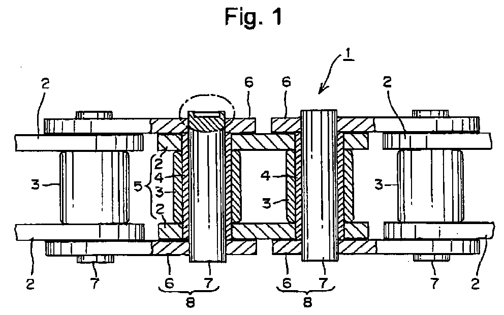
- An inner link 5 formed by press-fitting both end portions of a pair of bushes 4 each having a rotatable roller 3 into bush press-fitting holes of a pair of inner plates 2 and an outer link 8 formed by press-fitting both end portions of a pair of pins 7 into pin press-fitting holes of a pair of outer plates 6 are connected to each other by the pins 7, which penetrate through the bushes 4.
- both protruded end portions of the pin 7 are caulked with a caulking mold 11 shown in FIGS. 5 and 6.
- a longitudinal shallow groove 11a is formed on one side of the mold 11 as shown in FIG. 6, and a bottom surface 11b of this shallow groove 11a provides a flat surface. Further, a longitudinal V-groove 11c is formed on the bottom surface 11b.
- the constructed example as described above has the following actions and effects. Namely, caulking of the pin 7 can be performed with a pair of upper and lower molds 11 having a simple configuration. Further, since the thin wall thickness hollow cylindrical portion 7a of the pin 7 is pressed at the caulking of the pin 7, even a small pressing load may be used so that ease of the caulking of the pin 7 is improved.
- the pulling out of the pin is easily made by contacting a circular shallow recess 7b of the pin 7 with the top end of a punch and tapping it with the punch. Further, at the pulling out of the pin it is not necessary to remove a caulked portion of the pin 7. Therefore, the ease of displacement of the roller chain 1 is improved.
- convex portions 7e (caulked marks) each having a V-shaped cross section are formed on both end surfaces of a hollow cylindrical portion 7a of the pin 7, the determination whether caulking was made or not can be identified visually by presence or absence of a caulked mark, and a caulking mistake can be prevented. Further, since this convex portion 7e (caulked mark) having the V-shaped cross section is formed on the both end surfaces of the hollow cylindrical portion 7a of the pin 7 on a pitch line 9 formed by connecting the centers of end surfaces of a plurality of pins 7 of a roller chain, in a case where a high load is acted on the pin during use of the roller chain 1, the pin 7 can be rotated. However, the determination whether the pin was rotated or not can be identified visually by confirming whether the convex portion 7e (caulked mark) is shifted from the pitch line 9 and the finding of disadvantage in the roller chain 1 is easy.
- convex portions 7e (caulked marks) each having a V-shaped cross section are formed on both end portions of the hollow cylindrical portion 7a
- concave portions may be formed instead of the convex portions 7e each having the V-shaped cross section.
- a caulking mold is used in which an axial convexly protruded streak is axially formed on the bottom surface 11b of the groove 11a in the caulking mold 11.
- a caulked mark may be provided by forming a convex portion or a concave portion on only one end surface of this hollow cylindrical portion 7a.
- a caulking mold which opposes on the other end surface where a convex portion or a concave portion is not formed, a flat bottom surface 11b in the axial shallow groove 11a for the caulking mold 11 shown in FIG. 6 is used.
- a cross sectional shape of the convex portion or the concave portion forming a caulked mark is not limited particularly.
- roller chain 1 is shown.
- the inventions according to claims 1 and 2 can be applied to a bush chain having a roller.
Landscapes
- Engineering & Computer Science (AREA)
- General Engineering & Computer Science (AREA)
- Mechanical Engineering (AREA)
- Automatic Assembly (AREA)
- Chain Conveyers (AREA)
Abstract
Description
- The present invention relates to a chain in which an inner link farmed by press-fitting both end portions of a pair of bushes into bush press-fitting holes of a pair of inner plates and an outer link formed by press-fitting both end portions of a pair of pins into pin press-fitting holes of a pair of outer plates are connected to each other by said pins, which penetrate through said bushes and protruded end portions of said pin are caulked.
- In a chain in which an inner link formed by press-fitting both end portions of a pair of bushes into bush press-fitting holes of a pair of inner plates and an outer link formed by press-fitting both end portions of a pair of pins into pin press-fitting holes of a pair of outer plates are connected to each other by said pins, which penetrate through said bushes and protruded end portions of said pin are caulked, a roller chain in which both protruded end surfaces of the pin are caulked in a tapered manner has been known (see for example Patent Reference 1).
- However, in a roller chain disclosed in the above-mentioned Japanese Laid-open Patent Publication No. 2003-294090, both protruded end surfaces of the pin are caulked in a tapered manner. Thus, when a chain is displaced, after removing a caulked portion with a grinder or the like, a pin must be pulled out. Accordingly, there is a problem that the displacement operation of the chain is not easy.
- As a method for solving the above-mentioned problem, the following two methods have been performed. One method comprises caulking protruded both end portions of a hardness-reduced pin by subjecting the both end portions of the pin to previous annealing treatment. Since in this method the caulked portions of the pin are not hard, the pin can be pulled out through the inner surface of a bush by a punch even while the pin being caulked. The other method uses a pin previously subjected to copper plating on end portions of the pin and comprises caulking protruded both end portions of the pin. Since in this method the caulked portions of the pin are not hard, the pin can also be pulled out through the inner surface of a bush by a punch even while the pin being caulked.
- However, the above-mentioned two methods have the following problems respectively. Namely, since the above-mentioned one method comprises an annealing step it increases in cost. Further, since the caulking width is large, the pressing load during caulking is increased. On the other hand, since the other method comprises performing copper plating and removing the plating material, it not only increases in cost but also must care for environmental contamination. Further, since the caulking width is large, the pressing load during caulking is increased.
- Thus, the object of the present invention is to provide a chain in which the ease of the caulking of a pin and displacement of the chain is improved and cost reduction is possible.
- To solve the above-mentioned problems, according to the invention of claim 1, a chain in which an inner link formed by press-fitting both end portions of a pair of bushes into bush press-fitting holes of a pair of inner plates and an outer link formed by press-fitting both end portions of a pair of pins into pin press-fitting holes of a pair of outer plates are connected to each other by said pins, which penetrate through said bushes and protruded end portions of said pin are caulked, is characterized in that an end surface of a thin wall thickness hollow cylindrical portion formed on the protruded end portion of said pin is axially caulked so that an annular bulge portion having a substantially arc cross section is formed on the outer diameter side of said hollow cylindrical portion.
- To solve the above-mentioned problems, according to the invention of
claim 2, in the invention of claim 1, a caulked mark is formed on at least one end surface of said hollow cylindrical portion on a pitch line obtained by connecting the centers of end surfaces of a plurality of said pins. - The invention according to claim 1 has the following effects. Namely, in the invention of claim 1, the caulking of a pin can be made with a pair of upper and lower caulking molds each having a simple structure. Further, since in the caulking of the pin a thin wall thickness hollow cylindrical portion of a pin is pressed, even a small pressing load may be used and ease of the caulking of the pin is improved.
- Further, since a plastic deformation occurs on the inner diameter side (center side) of a hollow cylindrical portion of a pin at the caulking of the pin, the amount of plastic deformation on the outer diameter side of the hollow cylindrical portion is decreased so that an annular bulge portion having a substantially are cross section on the outer diameter side of the hollow cylindrical portion is slightly suppressed. Therefore, when a pin is pulled out by tapping it with a punch on the displacement of a chain, even if the pin is subjected to caulking with the pin usually heat-treated (carburized), and the pin can be easily passed through a pin press-fitting hole of the outer plate and an inner circumferential surface of a bush. Further, at the pulling out the pin, the pulling out of the pin is easily made by contacting a top end of a punch with a shallow circular recess of the pin to tap the recess with the punch. Further, at the pulling out of the pin it is not necessary to remove a caulked portion of the pin. Therefore, the ease of displacement of the chain is improved.
- Further, according to the invention of claim 1, since it is not necessary to previously anneal end portions of a pin or to previously copper plate end portions of a pin and make heat treatment unlike a conventional chain, it is not necessary to care for environment unlike a case of copper plating and an increase in cost does not occur.
- The invention of
claim 2 has the following effects in addition to the effects of the invention of claim 1. Since a caulked mark is formed on at least one end surface of a hollow cylindrical portion of a pin, the determination whether caulking was made or not can be identified visually by presence or absence of a caulked mark, and a caulking mistake can be prevented. Further, since this caulked mark is formed on at least one end surface of a hollow cylindrical portion of a pin on a pitch line formed by connecting the centers of end surfaces of a plurality of pins of a chain, in a case where a high load is acted on the pin during use of the chain, the pin can be rotated. However, the determination whether the pin was rotated or not can be identified visually by confirming whether the caulked mark is shifted from the pitch line and the finding of disadvantage in the chain is easy. - In a chain in which an inner link formed by press-fitting both end portions of a pair of bushes into bush press-fitting holes of a pair of inner plates and an outer link formed by press-fitting both end portions of a pair of pins into pin press-fitting holes of a pair of outer plates are connected to each other by the pins, which penetrate through said bushes and protruded end portions of said pin are caulked, an end surface of a thin wall thickness hollow cylindrical portion formed on the protruded end portion of said pin is axially caulked so that an annular bulge portion having a substantially arc cross section is formed on the outer diameter side of the hollow cylindrical portion, and a V-shaped cross sectional convex portions (caulked marks) are farmed on both end surfaces of the hollow cylindrical portion on a pitch line obtained by connecting the centers of end surfaces of a plurality of pins. The example will be described below.
- An example of the present invention will be described based on FIGS. 1 to 6. In a roller chain 1 of an example of the present invention shown in FIGS. 1 and 2. An
inner link 5 formed by press-fitting both end portions of a pair ofbushes 4 each having arotatable roller 3 into bush press-fitting holes of a pair ofinner plates 2 and anouter link 8 formed by press-fitting both end portions of a pair ofpins 7 into pin press-fitting holes of a pair ofouter plates 6 are connected to each other by thepins 7, which penetrate through thebushes 4. And as will be described later, in the roller chain 1 connected bypins 7, both protruded end portions of thepin 7 are caulked with acaulking mold 11 shown in FIGS. 5 and 6. - In both end portions of the
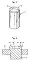
pin 7 circularshallow recesses 7b are formed as shown in FIG. 3, and these circularshallow recesses 7b form a thin wall thickness hollowcylindrical portion 7a is formed. - In a
caulking mold 11 for caulking both protruded end portions of thepin 7, a longitudinal shallow groove 11a is formed on one side of themold 11 as shown in FIG. 6, and abottom surface 11b of this shallow groove 11a provides a flat surface. Further, a longitudinal V-groove 11c is formed on thebottom surface 11b. - As shown in FIG. 5, when the
caulking molds 11 are disposed on both protruded end portions of thepin 7 in an opposed manner and pressing load is applied to thecaulking molds 11, the hollowcylindrical portions 7a of thepin 7 are axially pressed so that the hollowcylindrical portions 7a are plastically deformed and caulked. And this caulking due to axial pressing forms anannular bulge portion 7c of a substantially arc cross section on an outer diameter side at the hollowcylindrical portion 7a, and the caulking forms anannular bulge portion 7d of a substantially arc cross section on an inner diameter side (central side) at the hollowcylindrical portion 7a as shown in FIG. 4. At the same time, convexportions 7e (caulked marks) each having a V-shaped cross section are formed on both end surfaces of the hollowcylindrical portions 7a on apitch line 9 formed by connecting the centers of the end portions of a plurality ofpins 7. - The constructed example as described above has the following actions and effects. Namely, caulking of the
pin 7 can be performed with a pair of upper andlower molds 11 having a simple configuration. Further, since the thin wall thickness hollowcylindrical portion 7a of thepin 7 is pressed at the caulking of thepin 7, even a small pressing load may be used so that ease of the caulking of thepin 7 is improved. - Further, since a plastic deformation occurs on the inner diameter side (center side) of the hollow
cylindrical portion 7a of a pin at the caulking of the pin, the amount of plastic deformation on the outer diameter side of the hollow cylindrical portion is decreased so that anannular bulge portion 7c having a substantially arc cross section on the outer diameter side of the hollowcylindrical portion 7a is slightly suppressed. Therefore, when thepin 7 is pulled out by tapping it with a punch at the displacement of a roller chain 1, even if thepin 7 is subjected to caulking with the pin usually heat-treated (carburized), thepin 7 can be easily passed through a pin press-fitting hole of theouter plate 6 and an inner circumferential surface of abush 4. Further, at the pulling out the pin, the pulling out of the pin is easily made by contacting a circularshallow recess 7b of thepin 7 with the top end of a punch and tapping it with the punch. Further, at the pulling out of the pin it is not necessary to remove a caulked portion of thepin 7. Therefore, the ease of displacement of the roller chain 1 is improved. - Further, since convex
portions 7e (caulked marks) each having a V-shaped cross section are formed on both end surfaces of a hollowcylindrical portion 7a of thepin 7, the determination whether caulking was made or not can be identified visually by presence or absence of a caulked mark, and a caulking mistake can be prevented. Further, since thisconvex portion 7e (caulked mark) having the V-shaped cross section is formed on the both end surfaces of the hollowcylindrical portion 7a of thepin 7 on apitch line 9 formed by connecting the centers of end surfaces of a plurality ofpins 7 of a roller chain, in a case where a high load is acted on the pin during use of the roller chain 1, thepin 7 can be rotated. However, the determination whether the pin was rotated or not can be identified visually by confirming whether theconvex portion 7e (caulked mark) is shifted from thepitch line 9 and the finding of disadvantage in the roller chain 1 is easy. - Further, according to the example, since it is not necessary to previously anneal end portions of a pin or to previously copper plate end portions of a pin and make heat treatment unlike a conventional chain, it is not necessary to care for environment unlike a case of copper plating and an increase in cost does not occur.
- Further, although in the above-mentioned example, the
convex portions 7e (caulked marks) each having a V-shaped cross section are formed on both end portions of the hollowcylindrical portion 7a, concave portions may be formed instead of theconvex portions 7e each having the V-shaped cross section. When this concave portion is formed, a caulking mold is used in which an axial convexly protruded streak is axially formed on thebottom surface 11b of the groove 11a in thecaulking mold 11. - Alternatively, although in the example, the
convex portions 7e (caulked marks) each having a V-shaped cross section are formed on both end portions of the hollowcylindrical portion 7a, a caulked mark may be provided by forming a convex portion or a concave portion on only one end surface of this hollowcylindrical portion 7a. And when the convex portion or the concave portion is formed on only one end surface of this hollowcylindrical portion 7a, as a caulking mold, which opposes on the other end surface where a convex portion or a concave portion is not formed, aflat bottom surface 11b in the axial shallow groove 11a for thecaulking mold 11 shown in FIG. 6 is used. - Further, a cross sectional shape of the convex portion or the concave portion forming a caulked mark is not limited particularly.
- Further, in the example, the roller chain 1 is shown. However, the inventions according to
claims 1 and 2 can be applied to a bush chain having a roller. -
- [FIG. 1] FIG. 1 is a plan view showing a roller chain of an example of the present invention as a partial cross section.
- [FIG. 2] FIG. 2 is a side view of the roller chain shown in FIG. 1.
- [FIG. 3] FIG. 3 is a perspective view of a pin used in the roller chain shown in FIG. 1.
- [FIG. 4] FIG. 4 is a cross sectional view showing a part in the oval circle in FIG. 1.
- [FIG. 5] FIG. 5 is a schematic explanatory view showing a state when both protruded end portions of a pin in the roller chain of the example in the present invention is caulked with a caulking mold as a partial cross section.
- [FIG. 6] FIG. 6 is a perspective view of the caulking mold shown in FIG. 5.
-
-
- 1 ... Roller chain
- 2 ... Inner plate
- 3 ... Roller
- 4 ... Bush
- 5 ... Inner link
- 6 ... Outer plate
- 7 ... Pin
- 7a ... Hollow cylindrical portion
- 7b ... Circular shallow groove
- 7c ... Annular bulge portion having a substantially arc cross section on an outer diameter side
- 7d ... Annular bulge portion having a substantially arc cross section on an inner diameter side
- 7e ... Convex portion (caulked mark) having a V-shaped cross section
- 8 ... Outer link
- 9 ... Pitch line
- 11 ... Caulking mold
- 11a ... Axial shallow groove
- 11b ... Bottom surface of a groove
- 11c ... Axial V groove
-
Claims (2)
- A chain in which an inner link formed by press-fitting both end portions of a pair of bushes into bush press-fitting holes of a pair of inner plates and an outer link formed by press-fitting both end portions of a pair of pins into pin press-fitting holes of a pair of outer plates are connected to each other by said pins, which penetrate through said bushes and protruded end portions of said pin are caulked, characterized in that
an end surface of a thin wall thickness hollow cylindrical portion formed on the protruded end portion of said pin is axially caulked so that an annular bulge portion having a substantially arc cross section is formed on the outer diameter side of said hollow cylindrical portion. - A chain according to claim 1, characterized in that a caulked mark is formed on at least one end surface of said hollow cylindrical portion on a pitch line obtained by connecting the centers of end surfaces of a plurality of said pins.
Applications Claiming Priority (2)
| Application Number | Priority Date | Filing Date | Title |
|---|---|---|---|
| JP2004181192 | 2004-06-18 | ||
| JP2004181192A JP3905530B2 (en) | 2004-06-18 | 2004-06-18 | chain |
Publications (3)
| Publication Number | Publication Date |
|---|---|
| EP1607656A2 true EP1607656A2 (en) | 2005-12-21 |
| EP1607656A3 EP1607656A3 (en) | 2006-03-08 |
| EP1607656B1 EP1607656B1 (en) | 2011-08-24 |
Family
ID=34975200
Family Applications (1)
| Application Number | Title | Priority Date | Filing Date |
|---|---|---|---|
| EP20050007770 Expired - Lifetime EP1607656B1 (en) | 2004-06-18 | 2005-04-08 | Chain |
Country Status (2)
| Country | Link |
|---|---|
| EP (1) | EP1607656B1 (en) |
| JP (1) | JP3905530B2 (en) |
Cited By (4)
| Publication number | Priority date | Publication date | Assignee | Title |
|---|---|---|---|---|
| CN102974747A (en) * | 2012-10-18 | 2013-03-20 | 安徽朝阳车链有限公司 | Chain automatic heading device |
| CN105798589A (en) * | 2016-05-16 | 2016-07-27 | 杭州盾牌链条有限公司 | Automatic assembly machine achieving double pin and sheet discharging |
| CN107588154A (en) * | 2017-09-12 | 2018-01-16 | 湖州锐狮标准件制造有限公司 | Dolioform chain roller and its manufacturing process |
| CN111069523A (en) * | 2020-01-07 | 2020-04-28 | 安徽黄山中友链条制造有限公司 | Rivet head exposing device for hollow pin shaft of chain |
Families Citing this family (4)
| Publication number | Priority date | Publication date | Assignee | Title |
|---|---|---|---|---|
| JP2009085238A (en) * | 2007-09-27 | 2009-04-23 | Tsubakimoto Chain Co | Chain |
| JP7465064B2 (en) * | 2019-04-16 | 2024-04-10 | 大同工業株式会社 | Manufacturing method of chain joint pin |
| CN111687372B (en) * | 2020-05-21 | 2021-12-03 | 杭州传智自动化科技有限公司 | Horizontal assembly machine for slide plate chain |
| JP7472737B2 (en) * | 2020-09-23 | 2024-04-23 | カシオ計算機株式会社 | Chain inspection device, chain inspection method, and program |
Citations (1)
| Publication number | Priority date | Publication date | Assignee | Title |
|---|---|---|---|---|
| JP2003294090A (en) | 2002-04-01 | 2003-10-15 | Oriental Chain Mfg Co Ltd | Bush for roller chain and roller chain using the same |
Family Cites Families (3)
| Publication number | Priority date | Publication date | Assignee | Title |
|---|---|---|---|---|
| JPS53124964U (en) * | 1977-02-18 | 1978-10-04 | ||
| JPH0441039A (en) * | 1990-06-07 | 1992-02-12 | Fukusen Kogyo Kofun Yugenkoshi | Manufacture of roller chain |
| GB2257221B (en) * | 1991-07-03 | 1994-11-16 | Chia Long Wu | Chain pin |
-
2004
- 2004-06-18 JP JP2004181192A patent/JP3905530B2/en not_active Expired - Lifetime
-
2005
- 2005-04-08 EP EP20050007770 patent/EP1607656B1/en not_active Expired - Lifetime
Patent Citations (1)
| Publication number | Priority date | Publication date | Assignee | Title |
|---|---|---|---|---|
| JP2003294090A (en) | 2002-04-01 | 2003-10-15 | Oriental Chain Mfg Co Ltd | Bush for roller chain and roller chain using the same |
Cited By (5)
| Publication number | Priority date | Publication date | Assignee | Title |
|---|---|---|---|---|
| CN102974747A (en) * | 2012-10-18 | 2013-03-20 | 安徽朝阳车链有限公司 | Chain automatic heading device |
| CN105798589A (en) * | 2016-05-16 | 2016-07-27 | 杭州盾牌链条有限公司 | Automatic assembly machine achieving double pin and sheet discharging |
| CN105798589B (en) * | 2016-05-16 | 2017-12-29 | 杭州盾牌链条有限公司 | It is double go out selling sheet automatic assembling machine |
| CN107588154A (en) * | 2017-09-12 | 2018-01-16 | 湖州锐狮标准件制造有限公司 | Dolioform chain roller and its manufacturing process |
| CN111069523A (en) * | 2020-01-07 | 2020-04-28 | 安徽黄山中友链条制造有限公司 | Rivet head exposing device for hollow pin shaft of chain |
Also Published As
| Publication number | Publication date |
|---|---|
| JP3905530B2 (en) | 2007-04-18 |
| EP1607656A3 (en) | 2006-03-08 |
| EP1607656B1 (en) | 2011-08-24 |
| JP2006002891A (en) | 2006-01-05 |
Similar Documents
| Publication | Publication Date | Title |
|---|---|---|
| EP1607656B1 (en) | Chain | |
| CN1932332B (en) | Chain and method for blanking hole in chain plate | |
| US20140038759A1 (en) | Chain connecting pin | |
| US20060039778A1 (en) | Stamped rivet | |
| JP2003004051A (en) | Trail ring of shell shape needle roller bearing and its manufacturing method | |
| EP1070873A1 (en) | Tapered bushing for a roller chain | |
| JP3711467B2 (en) | Roller chain and its bush | |
| US20020095790A1 (en) | Retention method of a bearing | |
| JP2000218446A (en) | Bush processing method | |
| JP2000120411A5 (en) | ||
| JP4928331B2 (en) | Shell outer ring manufacturing method and shell needle roller bearing | |
| JP2003088937A (en) | Retaining ring | |
| JP7587720B2 (en) | Chain joint pin | |
| EP1953414B1 (en) | Power transmission chain pin and manufacture method thereof | |
| JP2023044988A (en) | ball bearing | |
| JP2003071538A (en) | Manufacturing method of pipe-shaped processed goods | |
| JP2008111469A (en) | Manufacturing method of outer ring member for constant velocity joint | |
| KR100621965B1 (en) | Method and apparatus for joining plates by caulking | |
| JP4823208B2 (en) | Manufacturing method of roller chain link plate | |
| JP4345529B2 (en) | Manufacturing method of outer ring of shell type full complement roller bearing | |
| JP2026048422A (en) | Wave spring and method for manufacturing wave spring | |
| JP2005221004A (en) | Roller bearing cage and rolling bearing | |
| JP2009204059A (en) | Hose fastening device, and sleeve caulking method and device | |
| JP2005321077A (en) | Pin type cage | |
| JP3718612B2 (en) | Bearing steel shaft parts |
Legal Events
| Date | Code | Title | Description |
|---|---|---|---|
| PUAI | Public reference made under article 153(3) epc to a published international application that has entered the european phase |
Free format text: ORIGINAL CODE: 0009012 |
|
| AK | Designated contracting states |
Kind code of ref document: A2 Designated state(s): AT BE BG CH CY CZ DE DK EE ES FI FR GB GR HU IE IS IT LI LT LU MC NL PL PT RO SE SI SK TR |
|
| AX | Request for extension of the european patent |
Extension state: AL BA HR LV MK YU |
|
| PUAL | Search report despatched |
Free format text: ORIGINAL CODE: 0009013 |
|
| AK | Designated contracting states |
Kind code of ref document: A3 Designated state(s): AT BE BG CH CY CZ DE DK EE ES FI FR GB GR HU IE IS IT LI LT LU MC NL PL PT RO SE SI SK TR |
|
| AX | Request for extension of the european patent |
Extension state: AL BA HR LV MK YU |
|
| RIC1 | Information provided on ipc code assigned before grant |
Ipc: F16G 13/06 20060101AFI20050927BHEP Ipc: B21L 9/06 20060101ALI20060118BHEP |
|
| 17P | Request for examination filed |
Effective date: 20060614 |
|
| AKX | Designation fees paid |
Designated state(s): DE FR GB IT NL |
|
| 17Q | First examination report despatched |
Effective date: 20061106 |
|
| GRAP | Despatch of communication of intention to grant a patent |
Free format text: ORIGINAL CODE: EPIDOSNIGR1 |
|
| GRAS | Grant fee paid |
Free format text: ORIGINAL CODE: EPIDOSNIGR3 |
|
| GRAA | (expected) grant |
Free format text: ORIGINAL CODE: 0009210 |
|
| AK | Designated contracting states |
Kind code of ref document: B1 Designated state(s): DE FR GB IT NL |
|
| REG | Reference to a national code |
Ref country code: GB Ref legal event code: FG4D |
|
| REG | Reference to a national code |
Ref country code: DE Ref legal event code: R096 Ref document number: 602005029660 Country of ref document: DE Effective date: 20111027 |
|
| REG | Reference to a national code |
Ref country code: NL Ref legal event code: T3 |
|
| PLBE | No opposition filed within time limit |
Free format text: ORIGINAL CODE: 0009261 |
|
| STAA | Information on the status of an ep patent application or granted ep patent |
Free format text: STATUS: NO OPPOSITION FILED WITHIN TIME LIMIT |
|
| 26N | No opposition filed |
Effective date: 20120525 |
|
| REG | Reference to a national code |
Ref country code: DE Ref legal event code: R097 Ref document number: 602005029660 Country of ref document: DE Effective date: 20120525 |
|
| REG | Reference to a national code |
Ref country code: FR Ref legal event code: PLFP Year of fee payment: 12 |
|
| REG | Reference to a national code |
Ref country code: FR Ref legal event code: PLFP Year of fee payment: 13 |
|
| REG | Reference to a national code |
Ref country code: FR Ref legal event code: PLFP Year of fee payment: 14 |
|
| PGFP | Annual fee paid to national office [announced via postgrant information from national office to epo] |
Ref country code: NL Payment date: 20240315 Year of fee payment: 20 |
|
| PGFP | Annual fee paid to national office [announced via postgrant information from national office to epo] |
Ref country code: GB Payment date: 20240229 Year of fee payment: 20 |
|
| PGFP | Annual fee paid to national office [announced via postgrant information from national office to epo] |
Ref country code: IT Payment date: 20240313 Year of fee payment: 20 Ref country code: FR Payment date: 20240308 Year of fee payment: 20 |
|
| PGFP | Annual fee paid to national office [announced via postgrant information from national office to epo] |
Ref country code: DE Payment date: 20240227 Year of fee payment: 20 |
|
| REG | Reference to a national code |
Ref country code: DE Ref legal event code: R071 Ref document number: 602005029660 Country of ref document: DE |
|
| REG | Reference to a national code |
Ref country code: NL Ref legal event code: MK Effective date: 20250407 |
|
| REG | Reference to a national code |
Ref country code: GB Ref legal event code: PE20 Expiry date: 20250407 |
|
| PG25 | Lapsed in a contracting state [announced via postgrant information from national office to epo] |
Ref country code: GB Free format text: LAPSE BECAUSE OF EXPIRATION OF PROTECTION Effective date: 20250407 |