EP1607650A1 - Control device for vehicle with auto clutch, control method thereof, and vehicle - Google Patents
Control device for vehicle with auto clutch, control method thereof, and vehicle Download PDFInfo
- Publication number
- EP1607650A1 EP1607650A1 EP05013007A EP05013007A EP1607650A1 EP 1607650 A1 EP1607650 A1 EP 1607650A1 EP 05013007 A EP05013007 A EP 05013007A EP 05013007 A EP05013007 A EP 05013007A EP 1607650 A1 EP1607650 A1 EP 1607650A1
- Authority
- EP
- European Patent Office
- Prior art keywords
- clutch
- vehicle
- temperature
- auto
- restraint
- Prior art date
- Legal status (The legal status is an assumption and is not a legal conclusion. Google has not performed a legal analysis and makes no representation as to the accuracy of the status listed.)
- Granted
Links
- 238000000034 method Methods 0.000 title claims abstract description 21
- 230000005856 abnormality Effects 0.000 claims abstract description 43
- 230000005540 biological transmission Effects 0.000 claims description 86
- 238000012546 transfer Methods 0.000 claims description 25
- 238000010586 diagram Methods 0.000 claims description 23
- 230000007423 decrease Effects 0.000 claims description 15
- 230000002159 abnormal effect Effects 0.000 claims description 12
- 238000001514 detection method Methods 0.000 claims description 6
- 238000004364 calculation method Methods 0.000 description 17
- 238000013021 overheating Methods 0.000 description 17
- 230000003247 decreasing effect Effects 0.000 description 16
- 238000012937 correction Methods 0.000 description 8
- 238000012545 processing Methods 0.000 description 5
- 230000002829 reductive effect Effects 0.000 description 5
- 238000002347 injection Methods 0.000 description 3
- 239000007924 injection Substances 0.000 description 3
- 239000000314 lubricant Substances 0.000 description 3
- 230000007935 neutral effect Effects 0.000 description 3
- 239000000498 cooling water Substances 0.000 description 2
- 239000000446 fuel Substances 0.000 description 2
- 238000003825 pressing Methods 0.000 description 2
- 230000000630 rising effect Effects 0.000 description 2
- 238000010008 shearing Methods 0.000 description 2
- 238000004904 shortening Methods 0.000 description 2
- 230000001360 synchronised effect Effects 0.000 description 2
- 230000001133 acceleration Effects 0.000 description 1
- 238000013500 data storage Methods 0.000 description 1
- 230000002349 favourable effect Effects 0.000 description 1
- 230000020169 heat generation Effects 0.000 description 1
- 230000000670 limiting effect Effects 0.000 description 1
- 230000000873 masking effect Effects 0.000 description 1
- 230000000452 restraining effect Effects 0.000 description 1
- 239000007858 starting material Substances 0.000 description 1
Images




Classifications
-
- F—MECHANICAL ENGINEERING; LIGHTING; HEATING; WEAPONS; BLASTING
- F16—ENGINEERING ELEMENTS AND UNITS; GENERAL MEASURES FOR PRODUCING AND MAINTAINING EFFECTIVE FUNCTIONING OF MACHINES OR INSTALLATIONS; THERMAL INSULATION IN GENERAL
- F16D—COUPLINGS FOR TRANSMITTING ROTATION; CLUTCHES; BRAKES
- F16D48/00—External control of clutches
- F16D48/06—Control by electric or electronic means, e.g. of fluid pressure
- F16D48/068—Control by electric or electronic means, e.g. of fluid pressure using signals from a manually actuated gearshift linkage
-
- B—PERFORMING OPERATIONS; TRANSPORTING
- B60—VEHICLES IN GENERAL
- B60W—CONJOINT CONTROL OF VEHICLE SUB-UNITS OF DIFFERENT TYPE OR DIFFERENT FUNCTION; CONTROL SYSTEMS SPECIALLY ADAPTED FOR HYBRID VEHICLES; ROAD VEHICLE DRIVE CONTROL SYSTEMS FOR PURPOSES NOT RELATED TO THE CONTROL OF A PARTICULAR SUB-UNIT
- B60W10/00—Conjoint control of vehicle sub-units of different type or different function
- B60W10/02—Conjoint control of vehicle sub-units of different type or different function including control of driveline clutches
-
- B—PERFORMING OPERATIONS; TRANSPORTING
- B60—VEHICLES IN GENERAL
- B60W—CONJOINT CONTROL OF VEHICLE SUB-UNITS OF DIFFERENT TYPE OR DIFFERENT FUNCTION; CONTROL SYSTEMS SPECIALLY ADAPTED FOR HYBRID VEHICLES; ROAD VEHICLE DRIVE CONTROL SYSTEMS FOR PURPOSES NOT RELATED TO THE CONTROL OF A PARTICULAR SUB-UNIT
- B60W10/00—Conjoint control of vehicle sub-units of different type or different function
- B60W10/04—Conjoint control of vehicle sub-units of different type or different function including control of propulsion units
- B60W10/06—Conjoint control of vehicle sub-units of different type or different function including control of propulsion units including control of combustion engines
-
- B—PERFORMING OPERATIONS; TRANSPORTING
- B60—VEHICLES IN GENERAL
- B60W—CONJOINT CONTROL OF VEHICLE SUB-UNITS OF DIFFERENT TYPE OR DIFFERENT FUNCTION; CONTROL SYSTEMS SPECIALLY ADAPTED FOR HYBRID VEHICLES; ROAD VEHICLE DRIVE CONTROL SYSTEMS FOR PURPOSES NOT RELATED TO THE CONTROL OF A PARTICULAR SUB-UNIT
- B60W10/00—Conjoint control of vehicle sub-units of different type or different function
- B60W10/18—Conjoint control of vehicle sub-units of different type or different function including control of braking systems
- B60W10/184—Conjoint control of vehicle sub-units of different type or different function including control of braking systems with wheel brakes
-
- B—PERFORMING OPERATIONS; TRANSPORTING
- B60—VEHICLES IN GENERAL
- B60W—CONJOINT CONTROL OF VEHICLE SUB-UNITS OF DIFFERENT TYPE OR DIFFERENT FUNCTION; CONTROL SYSTEMS SPECIALLY ADAPTED FOR HYBRID VEHICLES; ROAD VEHICLE DRIVE CONTROL SYSTEMS FOR PURPOSES NOT RELATED TO THE CONTROL OF A PARTICULAR SUB-UNIT
- B60W30/00—Purposes of road vehicle drive control systems not related to the control of a particular sub-unit, e.g. of systems using conjoint control of vehicle sub-units
- B60W30/18—Propelling the vehicle
- B60W30/184—Preventing damage resulting from overload or excessive wear of the driveline
- B60W30/1843—Overheating of driveline components
-
- B—PERFORMING OPERATIONS; TRANSPORTING
- B60—VEHICLES IN GENERAL
- B60W—CONJOINT CONTROL OF VEHICLE SUB-UNITS OF DIFFERENT TYPE OR DIFFERENT FUNCTION; CONTROL SYSTEMS SPECIALLY ADAPTED FOR HYBRID VEHICLES; ROAD VEHICLE DRIVE CONTROL SYSTEMS FOR PURPOSES NOT RELATED TO THE CONTROL OF A PARTICULAR SUB-UNIT
- B60W2510/00—Input parameters relating to a particular sub-units
- B60W2510/02—Clutches
- B60W2510/0291—Clutch temperature
-
- B—PERFORMING OPERATIONS; TRANSPORTING
- B60—VEHICLES IN GENERAL
- B60W—CONJOINT CONTROL OF VEHICLE SUB-UNITS OF DIFFERENT TYPE OR DIFFERENT FUNCTION; CONTROL SYSTEMS SPECIALLY ADAPTED FOR HYBRID VEHICLES; ROAD VEHICLE DRIVE CONTROL SYSTEMS FOR PURPOSES NOT RELATED TO THE CONTROL OF A PARTICULAR SUB-UNIT
- B60W2540/00—Input parameters relating to occupants
- B60W2540/10—Accelerator pedal position
-
- B—PERFORMING OPERATIONS; TRANSPORTING
- B60—VEHICLES IN GENERAL
- B60W—CONJOINT CONTROL OF VEHICLE SUB-UNITS OF DIFFERENT TYPE OR DIFFERENT FUNCTION; CONTROL SYSTEMS SPECIALLY ADAPTED FOR HYBRID VEHICLES; ROAD VEHICLE DRIVE CONTROL SYSTEMS FOR PURPOSES NOT RELATED TO THE CONTROL OF A PARTICULAR SUB-UNIT
- B60W2710/00—Output or target parameters relating to a particular sub-units
- B60W2710/02—Clutches
- B60W2710/021—Clutch engagement state
- B60W2710/022—Clutch actuator position
-
- F—MECHANICAL ENGINEERING; LIGHTING; HEATING; WEAPONS; BLASTING
- F16—ENGINEERING ELEMENTS AND UNITS; GENERAL MEASURES FOR PRODUCING AND MAINTAINING EFFECTIVE FUNCTIONING OF MACHINES OR INSTALLATIONS; THERMAL INSULATION IN GENERAL
- F16D—COUPLINGS FOR TRANSMITTING ROTATION; CLUTCHES; BRAKES
- F16D2500/00—External control of clutches by electric or electronic means
- F16D2500/30—Signal inputs
- F16D2500/304—Signal inputs from the clutch
- F16D2500/30401—On-off signal indicating the engage or disengaged position of the clutch
-
- F—MECHANICAL ENGINEERING; LIGHTING; HEATING; WEAPONS; BLASTING
- F16—ENGINEERING ELEMENTS AND UNITS; GENERAL MEASURES FOR PRODUCING AND MAINTAINING EFFECTIVE FUNCTIONING OF MACHINES OR INSTALLATIONS; THERMAL INSULATION IN GENERAL
- F16D—COUPLINGS FOR TRANSMITTING ROTATION; CLUTCHES; BRAKES
- F16D2500/00—External control of clutches by electric or electronic means
- F16D2500/30—Signal inputs
- F16D2500/304—Signal inputs from the clutch
- F16D2500/30404—Clutch temperature
-
- F—MECHANICAL ENGINEERING; LIGHTING; HEATING; WEAPONS; BLASTING
- F16—ENGINEERING ELEMENTS AND UNITS; GENERAL MEASURES FOR PRODUCING AND MAINTAINING EFFECTIVE FUNCTIONING OF MACHINES OR INSTALLATIONS; THERMAL INSULATION IN GENERAL
- F16D—COUPLINGS FOR TRANSMITTING ROTATION; CLUTCHES; BRAKES
- F16D2500/00—External control of clutches by electric or electronic means
- F16D2500/30—Signal inputs
- F16D2500/304—Signal inputs from the clutch
- F16D2500/3042—Signal inputs from the clutch from the output shaft
- F16D2500/30426—Speed of the output shaft
-
- F—MECHANICAL ENGINEERING; LIGHTING; HEATING; WEAPONS; BLASTING
- F16—ENGINEERING ELEMENTS AND UNITS; GENERAL MEASURES FOR PRODUCING AND MAINTAINING EFFECTIVE FUNCTIONING OF MACHINES OR INSTALLATIONS; THERMAL INSULATION IN GENERAL
- F16D—COUPLINGS FOR TRANSMITTING ROTATION; CLUTCHES; BRAKES
- F16D2500/00—External control of clutches by electric or electronic means
- F16D2500/30—Signal inputs
- F16D2500/31—Signal inputs from the vehicle
- F16D2500/3108—Vehicle speed
-
- F—MECHANICAL ENGINEERING; LIGHTING; HEATING; WEAPONS; BLASTING
- F16—ENGINEERING ELEMENTS AND UNITS; GENERAL MEASURES FOR PRODUCING AND MAINTAINING EFFECTIVE FUNCTIONING OF MACHINES OR INSTALLATIONS; THERMAL INSULATION IN GENERAL
- F16D—COUPLINGS FOR TRANSMITTING ROTATION; CLUTCHES; BRAKES
- F16D2500/00—External control of clutches by electric or electronic means
- F16D2500/30—Signal inputs
- F16D2500/312—External to the vehicle
- F16D2500/3125—Driving resistance, i.e. external factors having an influence in the traction force, e.g. road friction, air resistance, road slope
- F16D2500/3127—Road slope
-
- F—MECHANICAL ENGINEERING; LIGHTING; HEATING; WEAPONS; BLASTING
- F16—ENGINEERING ELEMENTS AND UNITS; GENERAL MEASURES FOR PRODUCING AND MAINTAINING EFFECTIVE FUNCTIONING OF MACHINES OR INSTALLATIONS; THERMAL INSULATION IN GENERAL
- F16D—COUPLINGS FOR TRANSMITTING ROTATION; CLUTCHES; BRAKES
- F16D2500/00—External control of clutches by electric or electronic means
- F16D2500/30—Signal inputs
- F16D2500/314—Signal inputs from the user
- F16D2500/31406—Signal inputs from the user input from pedals
- F16D2500/3144—Accelerator pedal position
- F16D2500/31453—Accelerator pedal position threshold, e.g. switch
-
- F—MECHANICAL ENGINEERING; LIGHTING; HEATING; WEAPONS; BLASTING
- F16—ENGINEERING ELEMENTS AND UNITS; GENERAL MEASURES FOR PRODUCING AND MAINTAINING EFFECTIVE FUNCTIONING OF MACHINES OR INSTALLATIONS; THERMAL INSULATION IN GENERAL
- F16D—COUPLINGS FOR TRANSMITTING ROTATION; CLUTCHES; BRAKES
- F16D2500/00—External control of clutches by electric or electronic means
- F16D2500/50—Problem to be solved by the control system
- F16D2500/508—Relating driving conditions
- F16D2500/50825—Hill climbing or descending
-
- F—MECHANICAL ENGINEERING; LIGHTING; HEATING; WEAPONS; BLASTING
- F16—ENGINEERING ELEMENTS AND UNITS; GENERAL MEASURES FOR PRODUCING AND MAINTAINING EFFECTIVE FUNCTIONING OF MACHINES OR INSTALLATIONS; THERMAL INSULATION IN GENERAL
- F16D—COUPLINGS FOR TRANSMITTING ROTATION; CLUTCHES; BRAKES
- F16D2500/00—External control of clutches by electric or electronic means
- F16D2500/50—Problem to be solved by the control system
- F16D2500/508—Relating driving conditions
- F16D2500/50841—Hill hold
-
- F—MECHANICAL ENGINEERING; LIGHTING; HEATING; WEAPONS; BLASTING
- F16—ENGINEERING ELEMENTS AND UNITS; GENERAL MEASURES FOR PRODUCING AND MAINTAINING EFFECTIVE FUNCTIONING OF MACHINES OR INSTALLATIONS; THERMAL INSULATION IN GENERAL
- F16D—COUPLINGS FOR TRANSMITTING ROTATION; CLUTCHES; BRAKES
- F16D2500/00—External control of clutches by electric or electronic means
- F16D2500/50—Problem to be solved by the control system
- F16D2500/51—Relating safety
- F16D2500/5102—Detecting abnormal operation, e.g. unwanted slip or excessive temperature
-
- F—MECHANICAL ENGINEERING; LIGHTING; HEATING; WEAPONS; BLASTING
- F16—ENGINEERING ELEMENTS AND UNITS; GENERAL MEASURES FOR PRODUCING AND MAINTAINING EFFECTIVE FUNCTIONING OF MACHINES OR INSTALLATIONS; THERMAL INSULATION IN GENERAL
- F16D—COUPLINGS FOR TRANSMITTING ROTATION; CLUTCHES; BRAKES
- F16D2500/00—External control of clutches by electric or electronic means
- F16D2500/70—Details about the implementation of the control system
- F16D2500/704—Output parameters from the control unit; Target parameters to be controlled
- F16D2500/70422—Clutch parameters
- F16D2500/70438—From the output shaft
- F16D2500/7044—Output shaft torque
-
- F—MECHANICAL ENGINEERING; LIGHTING; HEATING; WEAPONS; BLASTING
- F16—ENGINEERING ELEMENTS AND UNITS; GENERAL MEASURES FOR PRODUCING AND MAINTAINING EFFECTIVE FUNCTIONING OF MACHINES OR INSTALLATIONS; THERMAL INSULATION IN GENERAL
- F16D—COUPLINGS FOR TRANSMITTING ROTATION; CLUTCHES; BRAKES
- F16D2500/00—External control of clutches by electric or electronic means
- F16D2500/70—Details about the implementation of the control system
- F16D2500/704—Output parameters from the control unit; Target parameters to be controlled
- F16D2500/70452—Engine parameters
- F16D2500/70458—Engine torque
-
- F—MECHANICAL ENGINEERING; LIGHTING; HEATING; WEAPONS; BLASTING
- F16—ENGINEERING ELEMENTS AND UNITS; GENERAL MEASURES FOR PRODUCING AND MAINTAINING EFFECTIVE FUNCTIONING OF MACHINES OR INSTALLATIONS; THERMAL INSULATION IN GENERAL
- F16H—GEARING
- F16H35/00—Gearings or mechanisms with other special functional features
- F16H35/10—Arrangements or devices for absorbing overload or preventing damage by overload
Definitions
- the present invention relates to a control device for a vehicle with an auto clutch, a control method and a vehicle, particularly to a control device for a vehicle with an auto clutch suitable to prevent the burnout due to overheating of the clutch, a control method thereof, and the vehicle.
- This transmission is an automatic transmission which comprises a gear train which can be freely rotated on the axis and a synchromesh, in which the synchromesh is switched by the actuator to carry out the gear shift.
- the gear type transmission is provided with at least one light and highly effective auto clutch in a driving system between an engine and the transmission to control a driving force transferred from the engine to the transmission, and control the engaging force of the clutch by the actuator automatically.
- This auto clutch transfers power by pressing the friction board.
- the auto clutch is made to be a state of half engagement of the clutch (state of slipping) from its release state at the start operation or shift operation to transfer power of the vehicle smoothly. Therefore, the clutch temperature rises because frictional heat by the state of half engagement of a clutch occurs voluminously, and the clutch might be damaged by burnout.
- the clutch is protected from being damaged due to overheating by completely releasing the clutch when the clutch temperature exceeds the limit value and intercepting the power transfer.
- An object of the present invention is to provide a control device for a vehicle with an auto clutch which is able to control unexpected roll back of the vehicle caused by the security function when the abnormality of a clutch is detected, a control method thereof, and a vehicle.
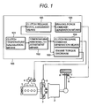
- FIG. 1 is a block diagram showing the entire configuration of a vehicle with an auto clutch according to a first embodiment of the present invention.
- Control unit 100 of the vehicle with an auto clutch calculates the temperature of clutch 3 provided between engine 1 and transmission 2.
- the torque generated by the engine is decreased, and the above-mentioned clutch 3 is released to intercept the power transfer from engine 1 when judged that the clutch is in the state of overheating.
- brake actuator 6 is operated to generate the braking force to the vehicle when it is judged that the above-mentioned clutch 3 is in a release state. That is, control unit 100 generates the restraint force by which the roll back of the vehicle is controlled.
- Control unit 100 is provided with clutch temperature calculation means 101, temperature abnormality judgment means 102, engine torque decrease command generation means 103, clutch release command generation means 104, clutch release state judgment means 105, and braking force command generation means 106.
- Clutch temperature calculation means 101 calculates the product of the calorie deprived outside of the clutch and the calorific value obtained from the difference of the rotation of the clutch and the transfer torque of the clutch.
- the signals of input rotating speed Ni from the input shaft speed sensor and the ignition switch operative position signal from the ignition switch described later by using FIG. 4 is input to clutch temperature calculation means 101, and the clutch temperature is calculated based on these signals.
- the method described in the Japanese Patent Application Laid-Open No. 8-230503, etc. for instance can be used to calculate the clutch temperature in clutch temperature calculation means 101.
- Temperature abnormality judgment means 102 the temperature of the compares the clutch temperature (Namely, clutch temperature detected with the temperature sensor) calculated by clutch temperature calculation means 101 with the predetermined threshold value (the clutch burnout temperature), and judges the abnormality of temperature of the clutch.
- This threshold can be set in stages according to the overheating degree.
- it is also possible to recommend the drive to the overheating control of the clutch by generating warning in driver beforehand in which not only the limit temperature to the burnout is judged, but also the slight overheating in the process on the way of the temperature rise.
- it is possible to control the temperature rise of the clutch by increment compensation of the clutch transfer torque to reduce the load of the clutch.
- Engine torque decrease command generation means 103 controls throttle actuator 4 provided in an intake pipe so that the engine speed may become the idling speed regardless of the driving demand from the driver when the abnormality of temperature is judged by temperature abnormality judgment means 102.
- Clutch release command generation means 104 outputs the command signal to release clutch 3 exceptionally regardless of the accelerator operation and the brake operation of the driver and intercepts the power transfer from engine 1 when the abnormality of temperature is judged by temperature abnormality judgment means 102. It is possible to control the overheating of clutch 3 and prevent the burnout thereof by this declutch operation or clutch release operation.
- Clutch release state judgment means 105 compares a signal from a clutch stroke sensor described later with the predetermined threshold value (declutch judgment position) after the abnormality of temperature is judged by temperature abnormality judgment means 102, and judges that clutch 3 is released and the torque transfer is intercepted.
- Clutch release state judgment means 105 inputs a stroke signal of clutch 3 from a clutch stroke sensor described later by using FIG. 4, a road inclination signal from an slope sensor and a signal indicative of the velocity of the wheel from a wheel speed sensor.
- Clutch release state judgment means 105 gives the braking force command to brake actuator 6 when it was judged that the clutch was released based on the above-mentioned information, and the vehicle runs at ultra low speed (1 km/h or less for instance) in the climb inclination.
- Braking force command generation means 106 gives the braking force command for stopping the vehicle to brake actuator 6 regardless of the brake operation of the driver when judged that the clutch was released by clutch release state judgment means 105.
- Brake actuator 6 operates brake friction pad 7 is operated according to a braking force command, and controls the rotation of brake disc 8 to stop the vehicle.
- control unit 100 by composing the principal part of control unit 100 as described above, it is possible to control the unexpected roll back of the vehicle caused by the clutch protection operation by controlling each actuator to generate the braking force to the vehicle when clutch 5 is released as clutch protection operation when the abnormality of a clutch is detected.
- control unit 100 calculates the clutch temperature, and detects the abnormality of temperature in the above explanation, it may be possible to adopt the configuration which detects the time required and the rotational fluctuation, etc. in the engage process of the clutch, and the abnormality of function such as change in the coefficient of friction of the clutch.
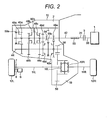
- FIG. 2 is a view showing the outline configuration of a transmission used for the vehicle with an auto clutch according to the first embodiment of the present invention.
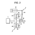
- FIG. 3 is a view showing the configuration of a clutch used for the vehicle with an auto clutch according to the first embodiment of the present invention.
- the driving force of engine 1 as a driving force for running or a motor is transferred to wheels 12R and 12L through clutch 3, gear type transmission 2, and differential gear device 18 as shown in FIG. 2.
- Clutch 3 is ,for instance, a friction clutch of the dry and single disk type shown in FIG. 3.
- Clutch 3 comprises flywheel 22 installed in crank shaft 20 of engine 1, clutch disk 26 provided to clutch output shaft 42, pressure plate 30 provided to clutch housing 28, and diaphragm spring 32 which transfer the power by enegizing pressure plate 30 to the flywheel 22 side and strongly thrusting clutch disk 26.
- Release sleeve 38 is shifted toward the left in FIG. 3 through release fork 36 by clutch release cylinder 34 which is clutch actuator 5.
- clutch actuator 5 is clutch actuator 5.
- diaphragm spring 32 is moved toward the left in the figure to release the clutch.
- Gear type transmission 2 is provided in the housing which is common with one of differential gear device 18, and composes a part of the transaxle as shown in FIG. 2.
- Gear type transmission 2 is soaked with the lubricant which is filled in housing 15 by a fixed amount, and is lubricated along with differential gear device 18.
- Gear type transmission 2 comprises: (a) a parallel two axes constant-mesh gear shift mechanism in which plural pairs of gear trains 46a, ⁇ , 46e with different gear ratio and constant-mesh are provided between a pair of input shaft 42 and output shaft 44 arranged in parallel, and plural synchronized mechanism (rotation synchronizer) are provided corresponding to those gear trains 46a, ⁇ , 46e, and (b) a shift selection shaft (not shown) which selectively moves either of three clutch hub sleeves 50a 50b or 50c of mesh type clutch 48a ⁇ 48e; and switches gear position. Therefore, forward gears have five gear positions.
- backward gear pair 54 is provided to input shaft 42 and output shaft 44, and engages with a backward idle gear provided to countershaft (not shown) to make the backward gear position.
- Input shaft 42 is connected with clutch output shaft 24 of said clutch 3, and output shaft 44 provided with output gear 56 is engaged with annular gear 58 of differential gear device 18.
- Clutch hub sleeve 50b is used for mesh type clutches 48b and 48c
- clutch hub sleeve 50c is used for mesh type clutches 48d and 48e.
- a shift selection shaft (not shown) is provided to rotate around the center of axle and move in an axial direction. The shift selection shaft is positioned at the following three positions in the axial direction by selection actuator (not shown). 1) A first selection position which can be connected with clutch hub sleeve 50c. 2) A second selection position which can be connected with clutch hub sleeve 50b. 3) A third selection position which can be connected with clutch hub sleeve 50a. Moreover, it is positioned at the following three positions around the center of axle by shift actuator (not shown).
- a neutral position (the state in FIG. 2) at the center where all mesh type clutches 48a - 48e are intercepted and the backward gear position is not formed. 5) a first shift position (the right side in FIG. 2) on both sides in the center of axle. 6) a second shift position (the left side in FIG. 2). It becomes the state (neutral state) of power transfer interception that the power transfer between input shaft 42 and output shaft 44 is intercepted in neutral position.
- the second gear position with the second largest transmission ratio e is formed by mesh type clutch 48d being connected at the second shift position of the first selection position.
- the third gear position with the third largest transmission ratio e is formed by mesh type clutch 48c being connected at the first shift position of the second selection position.
- the fourth gear position with the fourth largest transmission ratio e is formed by mesh type clutch 48b being connected at the second shift position of the second selection position.
- the fifth gear position with the smallest transmission ratio e is formed by mesh type clutch 48a being connected at the first shift position of the third selection position.
- the backward gear position with the smallest transmission ratio e is formed at the second shift position of the third selection position.
- Differential gear device 18 is one of a bevel gear type.
- Drive shafts 11 R and 11 L are connected with a couple of side gear 10R and 10L respectively by the spline engagement etc. to rotates the right and left front wheels (driving wheels) or rear wheels (driving wheels) 12R and 12L, respectively.
- Brake disc 7L is provided to driving wheel 12L, and the braking force is generated to the rotary motion of driving wheel 12L by operating brake friction pad 8L using brake actuator 6L.
- the brake disc, the brake actuator, and the brake friction pad (not shown) are also provided to driving wheel 12R.
- gear type transmission is used as a transmission in the above explanation, the configuration of the transmission is not limited to the gear type, a transmission with an auto clutch such as a continuously variable transmission can be used similarly.
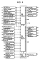
- FIG. 4 is a block diagram showing an electric control system of a control device for the vehicle with an auto clutch according to the first embodiment of the present invention.
- Control unit 100 comprises three electronic control units, electronic control unit (ECU: Electronic Control Unit) 200 for an engine, electronic control unit (ECU) 300 for a transmission and electronic control unit (ECU) 400 for a brake. Necessary information is exchanged via the telecommunication line between electronic control units.
- ECU 200, 300 and 400 is composed of a microcomputer.
- the signal processing is carried out according to the programs stored in ROMs beforehand while using the temporary data storage function of RAMs. It is also possible to use while rewriting a rewritable ROM in case of necessity by using it as the storage function.
- Ignition switch 71, engine speed sensor 72, output shaft speed sensor 73, accelerator pedal position sensor 74, air flow sensor 75, intake air temperature sensor 76, cooling water temperature sensor 77, brake switch 78, etc. are connected to ECU 200 for an engine. Signals indicative of the operative position of ignition switch 71, engine speed Ne, output shaft speed No, accelerator pedal position APS, intake air flow Q, intake air temperature Ta, engine cooling water temperature Tw, the operative position of brake switch 78, etc. are supplied to them, respectively.
- ECU 200 for an engine rotates starter 79 according to these input signals, starts engine 12, controls injection quantity of fuel injection valve 80 and fuel injection timing, or controls the ignition timing of a sparking plug by igniter 81.
- ECU 200 for an engine drives throttle actuator 4 further by inputting a necessary signal from ECU 300 for a transmission and controls the throttle opening.
- Oil pressure sensor 85, ignition switch 71, shift lever switch 86, auto mode switch 87, up-and-down switch 88, brake switch 78, input shaft speed sensor 89, clutch stroke sensor 90, shift position sensor 91, selection position sensor 92, and slope sensor 97, etc. are connected with ECU 300 for a transmission.
- ECU 300 for a transmission controls the operation of hydraulic pump 93 by inputting a necessary signal from the above-mentioned signals, and a necessary signal from ECU 200 for an engine control, and ECU 400 for a brake. Further, ECU 300 for a transmission switches the operation of the shift actuator and the selection actuator by changing clutch solenoid 94, shift solenoid 95, and selection solenoid 96, and controls the gear shift of gear type transmission 2 (including forward and backward speed switching control). In addition, it switches the operation of clutch release cylinder 34, and releases or engages clutch 3 at shifting.
- Wheel speed sensor 98, current sensor 99, etc. are connected with brake control unit 400.
- Brake control unit 400 controls brake actuator 6 by inputting a necessary signal from ECU 300 for a transmission, electric current lm of a motor (not shown) for brake actuator 6, and wheel speed VSP.
- Control unit 100 provides a command to decrease the engine torque as a security function at the abnormality of temperature of the clutch, and outputs an electric current command to clutch solenoid 94 in order to release clutch 3. Moreover, the control unit judges the release state of the clutch from a signal of clutch stroke sensor 90. When it is judged that it is a climb inclination based on a signal of slope sensor 97, the braking force generation demand is output to ECU 400 for a brake, brake actuator 6 is driven, and the braking force is generated. As a result, it becomes possible to prevent the burnout due to the overheating of the dutch and control the unexpected roll back of the vehicle caused by the clutch protection operation.
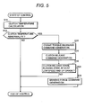
- FIG. 5 is a flow chart showing the content of the control of the control device for the vehicle with an auto clutch according to the first embodiment of the present invention.
- FIG. 6 is a timing chart showing the control operation of the control device for the vehicle with an auto clutch according to the first embodiment of the present invention.
- a of FIG. 6 shows the clutch temperature.
- B) shows input shaft speed Ni of the transmission and engine speed Ne,
- C) shows the clutch stroke,
- D) shows the clutch torque command,
- E shows the engine torque command, and
- F shows the brake motor torque.
- the axis of abscissas of FIG. 6 shows time.
- ECU300 (clutch temperature calculation means 101 in control unit 100 of FIG. 1) for a transmission calculates the clutch temperature based on the calorific value from clutch 3 in step s11 of FIG. 5.
- ECU 300 temperature abnormality judgment means 102 in control unit 100 of FIG. 1 for a transmission compares the clutch temperature calculated in step s11 with the predetermined threshold value, and judges the abnormality of temperature of the clutch in step s12. This control routine ends if the temperature is not abnormal. The processing advances to step s13 if judged the abnormality of temperature.
- ECU 300 engine torque decrease command generation means 103 in control unit 100 of FIG. 1 for a transmission outputs an engine torque decrease command to ECU 200 for an engine in step s13 if judged the abnormality of temperature.
- ECU 200 for an engine controls throttle actuator 4 regardless of a driving demand from a driver so that the engine speed may become the idling speed.
- FIG. 6 shows a timing chart of the start operation in the climb inclination.
- ECU 200 for an engine increases an engine torque command to generate the engine torque corresponding to the accelerator operation when the accelerator operation of driver is carried out at time t0 (see E).
- engine speed Ne rises (see B).
- the torque generated in the engine is presumed from engine speed Ne, accelerator position APS, intake air temperature Ta, and intake air flow Q, etc., based on a clutch torque command shown in (D) of FIG. 6.
- This presumption value is set to a clutch torque command value.
- the clutch stroke is changed the position of the release state to the position of the half engagement (see C), and the torque transfer in the clutch is begun.
- the engine torque command value is decreased to the value till which engine speed can maintain the idling rotation (see E).
- ECU 300 (clutch release command generation means 104 in control unit 100 of FIG. 1) for a transmission outputs a command signal to release clutch 3 exceptionally regardless of the accelerator operation and the brake operation by driver.
- clutch 3 is released by brake actuator 6, and the power transfer from the engine is intercepted. That is, the clutch torque command value is also decreased as shown in (D) of FIG. 6, and the clutch release operation is carried out.
- ECU300 (clutch release state judgment means 105 in control unit 100 of FIG. 1) for a transmission judges whether clutch 3 is released, and the speed of the vehicle is in the state of an ultra low speed and the vehicle are running on the climb inclination in step s15.
- This control routine ends when this condition is not satisfied, and the processing advances to step s16 when this condition is satisfied.
- ECU300 (braking force command generation means 106 in control unit 100 of FIG. 1) for a transmission outputs a demand command to generate the braking force to ECU 400 for a brake in step s16.
- ECU 400 for a brake gives the deterrent force to the roll back of the vehicle by driving brake actuator 6 regardless of the brake operation of this driver, and generating the braking force to the vehicle.
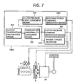
- FIG. 7 is a block diagram showing the entire configuration of a vehicle with an auto clutch according to a second embodiment of the present invention.
- FIG. 8 is a view showing the outline configuration of a transmission used for the vehicle with an auto clutch according to the second embodiment of the present invention.
- a transmission for a vehicle a FF (Front engine and Front drive) or a MR (Midship engine and Rear drive) vehicle is used.
- a FF Front engine and Front drive
- MR Magneticship engine and Rear drive
- FIG. 1 and FIG. 2 shows like parts.
- the block diagram showing the electric control system of the control device for the vehicle with an auto clutch according to this embodiment is similar to one in FIG. 4.
- torque transfer means (assist clutch) is provided to the gear train which forms a fifth gear position.
- the detailed configuration of the transmission 2A is described later by using FIG. 8.
- the control unit 100A is provided with restraint power command generation means 106A in place of braking force command generation means 106 shown in FIG. 1.
- the restraint power command generation means 106A provides a restraint power command to the transmission 2A to generate the restraint power to the vehicle regardless of the braking operation by a driver when judged that the clutch is released by clutch release state judgment means 105, and generates the restraint power to the power by which the vehicle is about to move backward by engaging the assistance clutch, and increasing the output shaft speed of the transmission 2A. That is, the control unit 100A generates the restraint force by which the roll back of the vehicle is controlled.
- Clutch drum 60a is fixed to the drive gear of gear train 46a which forms the fifth gear position, and a plurality of drive plates 60c rotate with clutch drum 60a as one body.
- clutch hub (not shown) is fixed to input shaft 42, and a plurality of driven plates 60b rotate with the clutch hub as one body.
- Drive plate 60c and driven plate 60b are well-known multiplate disk wet type disks which transfer the torque according to shearing force of the lubricant by axially pressing clutch piston (not shown) according to the pressure of the oil put between plates. Because the fifth gear position can be formed by engaging this multiplate disk wet type disk 60, mesh type clutch 48a according to shearing force of the lubricant and clutch hub sleeve 50a shown in FIG.
- multiplate disk wet type disk 60 is used as a assistance clutch (torque transfer means) which can change the speed without releasing clutch 3 by by-passing the torque of the engine to the output shaft via itself at the gear shift.
- clutch release command generation means 104 When temperature abnormality judgment means 102 in the control unit 100A shown in FIG. 7 judges the abnormality of temperature, clutch release command generation means 104 outputs a clutch release command.
- restraint power command generation means 106A When the release of the clutch is detected by clutch release state judgement means 105, restraint power command generation means 106A generates transfer torque of wet process multiple-disc clutch 60, and generates the restraint power to the output shaft of the transmission 2A.
- the control device and the control method of the vehicle with an auto clutch shown in FIG. 1 and FIG. 7 is for the processing when the temperature rises to the limit to the burnout due to the overheating of the clutch. They are final protection control systems. However, it is effective to control the heat generation of the clutch in the process to the above-mentioned limit value by judging the slight overheating and giving some treatment so as not to reach the above-mentioned limit value as the actual clutch protection control. Another embodiment is explained, in which the temperature rise of the clutch is controlled in the process to the above-mentioned limit value by judging the slight overheating of the clutch.
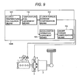
- FIG. 9 is a block diagram showing the entire configuration of a vehicle with an auto clutch according to a third embodiment of the present invention. Like numerals in FIG. 1 and FIG. 9 show like parts. Moreover, the block diagram showing the electric control system of the control device for the vehicle with an auto clutch according to this embodiment is similar to one in FIG. 4.
- Control unit 100B calculates the temperature of clutch 3 provided between engine 1 and gear type transmission 2. When the calculated temperature rises to a fixed value, control unit 100B judges the temperature rise of clutch 3. And, control unit 100B has the function as a temperature control means, by which the clutch torque is increased and the engine torque is increased or decreased according to the accelerator operation of driver when judged the temperature rise.
- Control unit 100B comprises clutch temperature calculation means 101, temperature rise judgment means 112, clutch torque increase correction means 113, accelerator operation judgment means 114, and engine torque correction means 115.
- Clutch temperature calculation means 101 calculates the clutch temperature by multiplying the calorific value obtained from the clutch transmission torque and the rotating speed difference of the clutch and the calorie deprived outside of the clutch as explained in FIG. 1.
- Temperature rise judgment means 112 compares the clutch temperature detected by the temperature sensor or that calculated by clutch temperature calculation means 101 with the predetermined threshold value (the temperature for the clutch temperature rise judgment), and judges the temperature rise of the clutch.
- This threshold value is set to the temperature lower than the limit value to the burnout of the clutch in temperature abnormality judgment means 102 of FIG. 1, and the set value is used as a threshold value to judge the comparatively slight overheating.
- Clutch torque increase means 113 decreases an amount of the slipping in the state of the half engagement of clutch 3 by increasing the clutch torque. In a word, heat load to the clutch is reduced by shortening the time required until the rotating speed difference of the clutch decreases.
- Accelerator operation judgment means 114 judges the presence of the accelerator operation by a driver based on a signal from accelerator pedal position sensor 114. More concretely, the accelerator operation is judged by ON/OFF of the idling switch. In the start operation from the stop state of the vehicle. The accelerator operation corresponds to the creep operation for idling switch ON.
- Engine torque correction means 115 controls throttle actuator 4 provided to the intake pipe to increase or decrease the engine torque according to the result of accelerator operation judgment means 114. More concretely, the engine torque is reduced when the accelerator operation is carried out, and the heat load to clutch 3 is reduced. If the engine torque is decreased when the accelerator operation is not carried out, the engine speed drops below the idling speed, and the behavior when creeping becomes unstable. As a result, something wrong such as the stop of the engine occurs. It is, therefore, necessary to increase the engine torque when the accelerator operation is not carried out.
- Each actuator is controlled by composing the principal part of control unit 100B like the above. Thereby, the temperature rise of the clutch in the start operation can be controlled without stopping the engine even when the temperature of clutch 3 rises to a fixed value.
- FIG. 10 is a flow chart showing the operation of a control device for the vehicle with an auto clutch according to the third embodiment of the present invention.
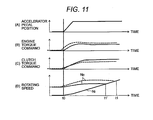
- FIG. 11 is a timing chart illustrating the operation of the control device for the vehicle with an auto clutch according to the third embodiment of the present invention.
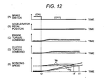
- FIG. 12 is a timing chart showing the control operation of the control device for the vehicle with an auto clutch according to the third embodiment of the present invention.
- ECU 300 (clutch temperature calculation means 101 in control unit 100 of FIG. 8) for a transmission shown in FIG. 4 calculates the temperature on the surface of the clutch from the calorific value of clutch 3 in step s21 of FIG. 10.
- ECU 300 temperature rise judgment means 112 in control unit 100 of FIG. 8 for a transmission compares the temperatures of the clutch calculated in step s21 with the threshold value set beforehand, and judges the temperature rise of the clutch. This control routine ends when judged the temperature is not rising, and the processing advances to step s23.
- ECU 300 (clutch torque increase correction means 113 of control unit 100 of FIG. 8) for a transmission increases the clutch torque and decreases an amount of slipping in the state of the half engagement of clutch 3 in step s23 when judged the temperature rise.
- the heat load to the clutch is reduced by shortening the time required until the rotating speed difference of the clutch disappears.
- ECU 300 (accelerator operation judgment means 114 in control unit 100 of FIG. 8) for a transmission judges the presence of the accelerator operation by a driver based on a signal from accelerator pedal position sensor 74 in step s24.
- ECU 300 (engine torque correction means 115 in control unit 100 of FIG. 8) for a transmission reduces the heat load to clutch 3 by outputting a command signal to ECU 200 for an engine to decrease the engine torque, and decreasing the throttle opening in step s25.
- ECU 300 engine torque correction means 115 in control unit 100 of FIG. 8 for an transmission controls the engine speed not to drop below the idling rotation by outputting a command signal to ECU 200 for an engine to increase the engine torque, and increasing the throttle opening in step s26.
- the temperature rise of the clutch in the start operation can be controlled without stopping the engine by controlling like this.
- FIG. 11 shows the accelerator position.
- the ordinate of FIG. 11 (B) shows the engine torque command.
- the ordinate of FIG. 11 (C) shows the clutch torque command.
- the ordinate of FIG. 11 (D) shows the rotating speed.
- the abscissa of FIG. 11 shows time. It should have been judged that the clutch temperature rise by step s22 before time t0.
- FIG. 11 (B), (C), and (D) show waveforms before it is judged the temperature rise in temperature rise judgment means 112. There is the rotating speed difference between engine speed Ne and input shaft speed Ni, when the temperature rise judgment is in failure. The so-called slipping continues until time t1.
- the clutch torque command is increased by clutch torque amendment means 113 after judging the temperature rise by temperature rise judgment means 112.
- the engine torque command is decreased by engine torque amendment means 115. Therefore, the load for the clutch is decreased and the temperature rise can be controlled because engine speed Ne is decreased and slipping is shortened in the period from time t1 to time t1' as shown by a solid line in FIG. 11 (D).
- FIG. 12 shows the state of the brake switch.
- the ordinate of FIG. 12 (B) shows the accelerator position.
- the ordinate of FIG. 12 (C) shows the engine torque command.
- the ordinate of FIG. 12 (D) shows the clutch torque command.
- the ordinate of FIG. 12 (E) shows the rotating speed.
- the axis of abscissas of FIG. 12 shows time. It should have been judged that the clutch temperature rise by step s22 before time t0.
- broken line in FIG. 12 shows the waveform before it is judged the temperature rise in temperature rise judgment means 112. The slipping continues until time t1 when the temperature rise judgment is in failure.
- the clutch torque command is increased by clutch torque amendment means 113 after judging the temperature rise by temperature rise judgment means 112.
- the engine torque command is also increased by engine torque amendment means 115. Therefore, the temperature rise can be controlled because engine speed Ne is decreased, input shaft speed Ni is increased and slipping is shortened in the period from time t1 to time t1' as shown by a solid line in FIG. 12 (E). Moreover, the engine is not stopped even by such a clutch overheating control action.
- the temperature rise of the clutch in the start operation can be controlled without stopping the engine by increasing the clutch torque, and switching the increase correction and the decrease correction of the engine torque based on the presence of the accelerator operation by a driver, when the clutch temperature is calculated as explained above and it is judged the temperature rise.
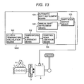
- FIG. 13 is a block diagram showing the entire configuration of a vehicle with an auto clutch according to a fourth embodiment of the present invention.
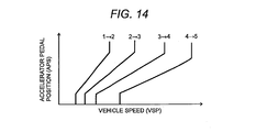
- FIG. 14 is an explanatory drawing showing the shift map in the vehicle with an auto clutch according to the fourth embodiment of the present invention.
- Like numerals in FIG. 1 and FIG. 9 show like parts.
- the block diagram showing the electric control system in the control device for the vehicle with an auto clutch according to this embodiment is similar to one in FIG. 4.
- the gear type transmission carries out the shift according to an automatic shift mode in which the following gear position is automatically decided based on the shift map obtained from the relationship between the accelerator position and the wheel speed, and a manual shift mode in which sequential up/down shifts are decided by the driver's intention.
- the shifting is carried out by operating shift/selection actuator 9, and switching the engaging of mesh type clutches 48a - 48e shown in FIG. 2.
- the automatic shift mode and the manual shift mode are selected with auto mode switch 87 which is switched by a driver as shown in FIG. 4.
- the traction control is carried out in the start operation on the snowy road, in which a vehicle is started after the start gear is set to the 2nd gear, because the coefficient of friction between the driving wheel and the road decreases and the wheels may slip.
- the switch from the start gear to the 2nd gear is carried out by inputting up switch 88 of FIG. 4 after driver's setting to the manual shift mode.
- there is another method of switching the start gear to 2nd gear similarly by separately providing a snow mode switch on the driver's seat, and recognizing this switch.
- the desired performance of the driving force is not obtained if such an operation is done when clutch 3 generates heat, and the temperature rise of the clutch will be promoted.
- the temperature of clutch 3 is calculated in this embodiment.
- the clutch temperature calculated is a fixed value or more, it is judged the temperature rise of clutch 3.
- the gear position selected at the start operation is limited when judged the temperature rise. More concretely, the start operation at a higher gear position excluding 1 st gear or the backward gear position is prohibited.
- Control unit 100 C has the function as a temperature control means as shown in FIG. 13.
- This control unit 100 C comprises clutch temperature calculation means 101, temperature rise judgment means 112, automatic shift settlement means 121, manual shift settlement means 122, shift mode switch means 123, and start gear position limitation means 126.
- Clutch temperature calculation means 101 calculates the clutch temperature by multiplying the calorific value obtained from the rotating speed difference of the clutch and the clutch transfer torque and the calorie deprived outside of the clutch.
- Temperature rise judgment means 112 compares the clutch temperature calculated by clutch temperature calculation means 101 or the clutch temperature detected with a temperature sensor with the threshold value (the temperature for the clutch temperature rise judgment) set beforehand, and judges the temperature rise of the clutch.
- This threshold value is set to the temperature lower than the limit value to the burnout of the clutch, and the set value is used as a threshold value to judge the comparatively slight overheating.
- Start gear limitation means 126 limits the selection of the gears at starting by masking a gear selection signal at starting if the driver selects a higher gear position excluding the 1 st gear or the backward gear at the start.
- Manual shift settlement means 122 decides the gear position in sequence according to a signal from up/down switch 88. However, when the selection of gear at starting is limited by start gear limitation means 126, limits only to the 1 st gear even if the 2nd gear is selected.
- Automatic shift settlement means 121 decides the gear position from the shift map shown in FIG. 14, based on signals from accelerator pedal position sensor 74 and output shaft rotation sensor 73. In the shift map, the gear position at that time is decided based on the vehicle speed (VSP) and the accelerator position (APS) as shown in FIG. 14.
- VSP vehicle speed
- APS accelerator position
- Shift mode switch means 123 selects either of the results of automatic shift settlement means 101 and manual shift settlement means 122 according to a signal from auto mode switch 87.
- FIG. 15 is a block diagram showing the entire configuration of a vehicle with an auto clutch according to a fifth embodiment of the present invention.
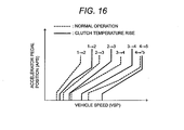
- FIG. 16 is an explanatory drawing showing the shift map in the vehicle with an auto clutch according to the fifth embodiment of the present invention.
- Like numerals in FIG. 1 and FIG. 9 show like parts.
- a block diagram showing the electric control system of the control device for the vehicle with an auto clutch according to this embodiment is similar to one in FIG. 4.
- Control unit 100D has the function as the temperature control means as shown in FIG. 15.
- Control unit 100D comprises clutch temperature calculation means 101, temperature rise judgment means 112, map switch means 131, map 132 in the normal operation, map 132 in the clutch temperature rise operation and shift command output means 134.
- map 132 in the normal operation and map 132 in the clutch temperature rise operation are explained by using FIG. 16.
- the dotted line usually shows a shift map in map 132 in the normal operation
- the solid line shows a shift map in map 132 in the clutch temperature rise operation.
- the shift diagram is usually set in the higher speed side compared with the map at the normal operation, and the shift frequency is decreased.
- clutch temperature calculation means 101 calculates the clutch temperature by multiplying the calorific value obtained from the clutch rotating speed difference and the clutch transfer torque and the calorie deprived outside of the clutch.
- Temperature rise judgment means 112 compares the clutch temperature calculated by clutch temperature calculation means 101 or the clutch temperature detected by the temperature sensor with the predetermined threshold value (clutch temperature rise judgment temperature), and judges the temperature rise of the clutch.
- the above-mentioned threshold is set to the temperature lower than the limit temperature to the burnout of the clutch, and assumed to be a threshold value by which the comparatively slight overheating is judged.
- Map switch means 131 selects map 132 in the clutch temperature rise operation when judged that the clutch temperature rises by temperature rise judgment means 112. The map is switched so that map 132 in the normal operation is selected when the clutch temperature does not rise.
- Shift command output means 134 selects the gear position according to the vehicle speed and the accelerator position which are input signals by using either map 132 in the normal operation or map 132 in the clutch temperature rise operation, outputs the shift command to shift/selection actuator 9, and executes the shift operation.
- the temperature rise of the clutch can be controlled by decreasing the engaging operation of the clutch, that is, the chance to enter the state of slipping by decreasing the shift frequency by using map 133.
- the temperature rise of the clutch in the start operation can be controlled by composing the principal part of control unit 100 as described above and controlling each actuator.
- the temperature rise of the clutch can be controlled by shifting the shift diagram to high-speed side as explained above.
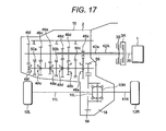
- FIG. 17 is a block diagram showing the entire configuration of the vehicle with an auto clutch according to the sixth embodiment of the present invention. Like numerals in FIG. 2 and FIG 17 show like parts. Moreover, the block diagram showing an electric control system of the control device for the vehicle with an auto clutch is similar to one in FIG. 4.
- the main configuration of the transmission according to this embodiment is similar to one in FIG. 2a.
- a gear type transmission of so-called twin clutch method is used, in which clutches 3A and 3B are provided between engine 1 and gear type transmission 2.
- the input shaft of this gear type transmission is made with hollow two axes.
- Constant-mesh gear trains 46f, 46c, and 46a are provided between the input shaft 42A and output shaft 44 connected with said clutch 3A, the gear ratio of the constant-mesh gear trains being different.
- Constant-mesh gear trains 46d, 46b, and 46e are provided between the input shaft 42B and output shaft 44 connected with said clutch 3B, the gear ratio of the constant-mesh gear trains being different.
- a plurality of mesh type clutches 48a, ⁇ , 48e with synchronized mechanism (rotary synchronizer) which correspond to these gear train 46a, ⁇ , 46e are provided to output shaft 44. Further, the shift selection shaft is provided to switch the gear position by selectively moving either of three clutch hub sleeves 50a, 50b and 50c of mesh type clutches 48a, ⁇ , 48e. As a result, six forward gears are formed.
- Gear train e corresponds to the gear train which forms a first gear position.
- Gear train e corresponds to the gear train which forms a first gear position.
- Gear train d corresponds to the gear train which forms a second gear position.
- Gear train c corresponds to the gear train which forms a third gear position.
- Gear train b corresponds to the gear train which forms a fourth gear position.
- Gear train a corresponds to the gear train which forms a fifth gear position.
- gear train f corresponds to the gear train which forms a sixth gear position. Therefore, when the shift is carried out in sequence, this gear type transmission changes the speed by switching the clutch so that one of clutch 3A and clutch 3B may be engaged and the other clutch may be released. As a result, the shift without the torque interruption is achieved.
- control method in the gear type transmission of such a twin clutch method is similar to that in control unit 100 shown in FIG. 1, control unit 100A shown in FIG. 7 or control unit 100C shown in FIG. 13.
- control unit 100 individually calculates the temperature of clutches 3A, 3B in FIG. 17, compares this clutch temperature with the temperature abnormality judgment value set beforehand, and judges the abnormality of the temperature. When judged the abnormality of temperature, control unit 100 decreases the engine torque, and releases the clutch 3A or clutch 3B whose temperature is abnormal. And, if the vehicle is running on the climb inclination and the release state of clutch 3A or clutch 3B is detected, the braking force to the vehicle is generated. It becomes possible by having such a function to control the unexpected roll back of the vehicle caused by the clutch protection operation by generating the braking force when the release state of the clutch is judged.
- control unit 100A individually calculates the temperature of clutches 3A, 3B, compares this clutch temperature with the clutch temperature rise judgment value set beforehand, and judges the rise of the temperature.
- the clutch torque is increased and the accelerator operation of driver is judged when judged the temperature rise.
- the engine torque is increased or decreased according to this judgment result, the heat load to the clutch 3A or clutch 3B is reduced.
- the temperature rise of the clutch in the start operation can be controlled without stopping the engine by having such a function.
- control unit 100 C individually calculates the temperature of clutches 3A, 3B, compares this clutch temperature with the clutch temperature rise judgment value set beforehand, and judges the rise of the temperature.
- the gear position selected in the start operation are limited when judged the temperature rise. More concretely, the start operation by the shift gear formed with the gear train which clings the input shaft 42A or 42B engaged to the clutch judged that the temperature is rising is prohibited.
- the temperature rise of the clutch in the start operation can be controlled by having such a function.
- control units 100, 100A execute the control when the temperature is abnormal
- control unit 100B, 100C, 100D execute the control at the temperature rise (when clutch temperature becomes the temperature more than the threshold value below the abnormal temperature).
- control unit 100B, 100C and 100D By providing either of the function of control unit 100 or control unit 100A or at least one of the function of control unit 100B, 100C and 100D to ECU 300, it may become possible to control so that the temperature should not rise at the temperature rise, and execute the control against the abnormality of temperature when the temperature rise cannot be prevented even by the control and the abnormality of temperature is occurred.
Landscapes
- Engineering & Computer Science (AREA)
- Mechanical Engineering (AREA)
- Chemical & Material Sciences (AREA)
- Combustion & Propulsion (AREA)
- Transportation (AREA)
- General Engineering & Computer Science (AREA)
- Automation & Control Theory (AREA)
- Physics & Mathematics (AREA)
- Fluid Mechanics (AREA)
- Hydraulic Clutches, Magnetic Clutches, Fluid Clutches, And Fluid Joints (AREA)
- Control Of Driving Devices And Active Controlling Of Vehicle (AREA)
- Regulating Braking Force (AREA)
Abstract
Description
Optionally, it is also possible to recommend the drive to the overheating control of the clutch by generating warning in driver beforehand in which not only the limit temperature to the burnout is judged, but also the slight overheating in the process on the way of the temperature rise. Alternatively, it is possible to control the temperature rise of the clutch by increment compensation of the clutch transfer torque to reduce the load of the clutch.
Claims (11)
- A control device for a vehicle with an auto clutch which can automatically operate engaging force of the clutch which controls the driving force transferred from an engine (1) to a transmission (2) by an actuator (5), comprising;an abnormal detection means (102) which detects abnormality of said clutch (3),a clutch release means (104) which releases said clutch (3) when abnormality of said clutch (3) is detected by this abnormal detection means,a clutch release state judgment means (105) which judges the release state of said clutch (3) by said clutch release means (104),a restraint force command generation means which generates a command to generate the restraint force to restrain the roll back of said vehicle when judged that said clutch (3) is released by said clutch release state judgment means (105), anda restraint force generation means which generates the restraint force to restrain the roll back of said vehicle based on the command from said restraint force command generation means.
- A control device for a vehicle with an auto clutch according to claim 1, wherein said restraint force generation means is a brake actuator (6).
- A control device for a vehicle with an auto clutch according to claim 1 or 2, wherein said transmission (2) is a gear type transmission, and said restraint force generation means is a torque transfer means provided between an input shaft and an output shaft of said gear type transmission.
- A control device for a vehicle with an auto clutch according to at least one of the claims 1 to 3, wherein when the temperature of said clutch (3) becomes more than the first predetermined temperature, said abnormal detection means (102) detects the abnormality of temperature of said clutch (3).
- A control device for a vehicle with an auto clutch according to at least one of the claims 1 to 4, wherein said restraint force command generation means generates the command to generate the restraint force when the vehicle is running in the climb inclination, and the accelerator operation of driver is carried out.
- A control device for a vehicle with an auto clutch according to at least one of the claims 1 to 5, further comprising:a temperature rise restraint command generation means (112) which generates the command to restrain temperature rise of said clutch (3) when temperature of said clutch (3) becomes more than the second fixed temperature lower than said the first fixed temperature, anda temperature rise restraint means which restrain the temperature rise of said clutch (3) based on the command from said temperature rise restraint command generation means (112).
- A control device for a vehicle with an auto clutch according to claim 6, wherein said temperature rise restraint means (112) increases the clutch torque of said clutch (3), and increases and decreases the engine torque of said engine (1).
- A control device for a vehicle with an auto clutch according to claim 6 or 7, wherein said temperature rise restraint means (112) limits the start gear position of said transmission (2) besides a high gear.
- A control device for a vehicle with an auto clutch according to at least one of the claims 6 to 8, wherein said temperature rise restraint means (112) sets the shift diagram of said transmission (2) in the high speed of car side.
- A method of controlling a vehicle with an auto clutch which can automatically operate engaging force of the clutch which controls the driving force transferred from an engine (1) to a transmission (2) by an actuator (5), comprising the steps of:releasing said clutch (3) when abnormality of said clutch is detected,generating a command to generate the restraint force to restrain the roll back of said vehicle when judged that said clutch is released, andgenerating the restraint force to control the roll back of said vehicle.
- A vehicle having an engine, a transmission, and an auto clutch which can automatically operate engaging force of the clutch which controls the driving force transferred from the engine (1) to the transmission (2) by an actuator (5), wherein said clutch (3) is released when abnormality of said clutch (3) is detected, and the restraint force to restrain the roll back of said vehicle is generated when judged that said clutch (3) is released.
Applications Claiming Priority (2)
| Application Number | Priority Date | Filing Date | Title |
|---|---|---|---|
| JP2004177956A JP2006001338A (en) | 2004-06-16 | 2004-06-16 | Control device, control method and vehicle for vehicle with automatic clutch |
| JP2004177956 | 2004-06-16 |
Publications (2)
| Publication Number | Publication Date |
|---|---|
| EP1607650A1 true EP1607650A1 (en) | 2005-12-21 |
| EP1607650B1 EP1607650B1 (en) | 2009-01-21 |
Family
ID=34937503
Family Applications (1)
| Application Number | Title | Priority Date | Filing Date |
|---|---|---|---|
| EP05013007A Expired - Lifetime EP1607650B1 (en) | 2004-06-16 | 2005-06-16 | Control device for vehicle with auto clutch, control method thereof, and vehicle |
Country Status (4)
| Country | Link |
|---|---|
| US (1) | US20050283298A1 (en) |
| EP (1) | EP1607650B1 (en) |
| JP (1) | JP2006001338A (en) |
| DE (1) | DE602005012458D1 (en) |
Cited By (5)
| Publication number | Priority date | Publication date | Assignee | Title |
|---|---|---|---|---|
| WO2013130233A1 (en) * | 2012-02-27 | 2013-09-06 | Chrysler Group Llc | Method and apparatus for controlling a clutch in four-wheel drive vehicles |
| US8989977B1 (en) | 2013-09-17 | 2015-03-24 | Robert Bosch Gmbh | Hill rollback speed control |
| FR3043379A1 (en) * | 2015-11-06 | 2017-05-12 | Renault Sas | METHOD FOR CONTROLLING THE DISPLACEMENT OF A VEHICLE EQUIPPED WITH AUTOMATED TRANSMISSION AT THE SECURE OPENING OF ITS CINEMARY CHAIN |
| EP2531739A4 (en) * | 2010-02-01 | 2018-04-18 | Scania CV AB | Method and system pertaining to an automatically controlled clutch |
| US11719293B2 (en) | 2021-12-01 | 2023-08-08 | Dana Automotive Systems Group, Llc | Diagnostic and control method for clutches in a vehicle system |
Families Citing this family (37)
| Publication number | Priority date | Publication date | Assignee | Title |
|---|---|---|---|---|
| DE102006003711A1 (en) * | 2006-01-26 | 2007-08-02 | Zf Friedrichshafen Ag | Method for control of vehicle with internal combustion engine and electric drive, comprises proportional reduction of torque at both drives |
| EP1994299B1 (en) * | 2006-03-02 | 2012-05-16 | Volvo Lastvagnar Ab | A method and a device for controlling a disc clutch |
| DE102006014141A1 (en) * | 2006-03-28 | 2007-10-04 | Zf Friedrichshafen Ag | Automatic friction clutch e.g. single-disk dry clutch, controlling method for motor vehicle, involves changing clutch torque to new reference value in pressure-controlled manner and adjusting pressure of actuator to another reference value |
| DE102006019824A1 (en) * | 2006-04-28 | 2007-10-31 | Zf Friedrichshafen Ag | Automated friction clutch`s e.g. single disk-dry clutch, torque characteristic determining method for motor vehicle, involves determining positions, while clutch is opened in neutral switched gear and continuous motor during closed clutch |
| JP4913535B2 (en) * | 2006-10-19 | 2012-04-11 | 本田技研工業株式会社 | Shift control device for automatic transmission |
| JP5131441B2 (en) | 2007-08-31 | 2013-01-30 | アイシン・エィ・ダブリュ株式会社 | Control device for automatic transmission and control method for automatic transmission |
| JP4946827B2 (en) * | 2007-11-27 | 2012-06-06 | 日産自動車株式会社 | Vehicle starting friction element control device |
| JP5007661B2 (en) * | 2007-11-27 | 2012-08-22 | 日産自動車株式会社 | Vehicle driving force control device |
| US8287433B2 (en) | 2008-01-10 | 2012-10-16 | Komatsu Ltd. | Work vehicle |
| JP5160363B2 (en) * | 2008-01-10 | 2013-03-13 | 株式会社小松製作所 | Motor grader |
| US8401750B2 (en) * | 2008-02-28 | 2013-03-19 | Volvo Lastvagnar Ab | Method and device for automatic or semiautomatic selection of a better starting gear in a vehicle |
| JP5063475B2 (en) * | 2008-05-13 | 2012-10-31 | 本田技研工業株式会社 | Clutch control device |
| JP5011573B2 (en) * | 2008-05-13 | 2012-08-29 | 本田技研工業株式会社 | Clutch control device |
| JP4921509B2 (en) | 2009-03-31 | 2012-04-25 | アイシン・エィ・ダブリュ株式会社 | Control device for automatic transmission |
| US8099226B2 (en) | 2009-11-06 | 2012-01-17 | Toyota Motor Engineering & Manufacturing North America, Inc. | Throttle compensation for second gear starts in manual transmission vehicles |
| JP5005054B2 (en) * | 2010-02-23 | 2012-08-22 | 本田技研工業株式会社 | Starting clutch control device |
| JP5506484B2 (en) * | 2010-03-23 | 2014-05-28 | アイシン・エーアイ株式会社 | Vehicle power transmission control device |
| JP5614236B2 (en) * | 2010-10-22 | 2014-10-29 | 日産自動車株式会社 | Control device for hybrid vehicle |
| JP5691429B2 (en) * | 2010-11-18 | 2015-04-01 | 日産自動車株式会社 | Overheat determination device for transmission and overheat prevention device using the same |
| CA2827879A1 (en) * | 2011-04-12 | 2012-10-18 | Chrysler Group Llc | Method for determining wet clutch temperature |
| TWI438105B (en) * | 2011-07-22 | 2014-05-21 | Kwang Yang Motor Co | The power generation system of a vehicle and its power generation method |
| JP5416194B2 (en) * | 2011-12-15 | 2014-02-12 | 本田技研工業株式会社 | Power transmission control device |
| KR101816322B1 (en) | 2012-07-16 | 2018-01-08 | 현대자동차주식회사 | Control method for preventing backward moving of hybrid electric vehicle |
| KR101519262B1 (en) * | 2013-12-18 | 2015-05-11 | 현대자동차주식회사 | Touch point adjusting method for dct |
| DE102015101806A1 (en) | 2014-09-23 | 2016-03-24 | Hyundai Motor Company | Method of protecting a clutch for a dual-clutch transmission |
| KR101628528B1 (en) | 2014-11-17 | 2016-06-09 | 현대자동차주식회사 | Touch point adjusting method for dct |
| US9855813B2 (en) * | 2014-12-04 | 2018-01-02 | Ford Global Technologies, Llc | System and methods for preventing wheel hop during a burnout event in a motor vehicle |
| KR101655692B1 (en) * | 2015-07-07 | 2016-09-08 | 현대자동차주식회사 | Method for preventing overheat of clutch |
| JP6714386B2 (en) * | 2016-02-25 | 2020-06-24 | 川崎重工業株式会社 | Bearing monitoring device for railway vehicles |
| KR101813542B1 (en) * | 2016-10-06 | 2018-01-30 | 현대자동차주식회사 | A hybrid vehicle and controlling method for the same |
| US10471941B2 (en) * | 2017-01-12 | 2019-11-12 | Ford Global Technologies, Llc | Power capture during a line lock event |
| KR102079948B1 (en) * | 2018-01-05 | 2020-02-21 | 주식회사 만도 | Vehicle control apparatus and vehicle control method |
| JP7091949B2 (en) | 2018-08-30 | 2022-06-28 | トヨタ自動車株式会社 | Vehicle control unit |
| KR102700161B1 (en) * | 2019-04-01 | 2024-08-28 | 에이치엘만도 주식회사 | Brake control device and control method thereof |
| JP7707994B2 (en) * | 2022-04-22 | 2025-07-15 | トヨタ自動車株式会社 | Control device |
| US12228178B2 (en) * | 2022-12-27 | 2025-02-18 | Kawasaki Motors, Ltd. | Vehicle, method for controlling vehicle and controller for vehicle |
| CN116771817A (en) * | 2023-08-24 | 2023-09-19 | 盛瑞传动股份有限公司 | Control method, device and equipment for gearbox and storage medium |
Citations (9)
| Publication number | Priority date | Publication date | Assignee | Title |
|---|---|---|---|---|
| US6033342A (en) * | 1998-02-17 | 2000-03-07 | Mannesmann Sachs Ag | Drive train arrangement for a motor vehicle driven by an internal combustion engine |
| US6039673A (en) * | 1997-12-08 | 2000-03-21 | Aisin Aw Co., Ltd. | Control system for automatic transmission |
| JP2002115582A (en) | 2000-10-12 | 2002-04-19 | Mitsubishi Electric Corp | Automatic clutch overheat protection device |
| WO2003058093A1 (en) * | 2002-01-10 | 2003-07-17 | Volvo Lastvagnar Ab | Motorized truck |
| FR2838489A1 (en) * | 2002-04-10 | 2003-10-17 | Luk Lamellen & Kupplungsbau | DEVICE AND METHOD FOR MONITORING A CLUTCH |
| US6679810B1 (en) * | 1998-10-14 | 2004-01-20 | Luk Lamellen Und Kupplungsbau Beteiligungs Kg | Hill holder device for a motor vehicle |
| US20040061603A1 (en) * | 2002-10-01 | 2004-04-01 | Mack William J. | Clutch protection system |
| US20040067818A1 (en) * | 2001-10-02 | 2004-04-08 | Claas Industrietechnik Gmbh | Method and apparatus for prolonging the life of a clutch |
| WO2004067312A2 (en) * | 2003-01-27 | 2004-08-12 | Luk Lamellen Und Kupplungsbau Beteiligungs Kg | Device for protecting the clutch of an automatic gearbox |
Family Cites Families (4)
| Publication number | Priority date | Publication date | Assignee | Title |
|---|---|---|---|---|
| US5376869A (en) * | 1993-02-11 | 1994-12-27 | General Electric Company | Electric vehicle drive train with rollback detection and compensation |
| DE19525552A1 (en) * | 1995-07-13 | 1997-01-16 | Teves Gmbh Alfred | Method and arrangement for holding a vehicle on an inclined road |
| DE19530612C2 (en) * | 1995-08-21 | 2002-06-27 | Daimler Chrysler Ag | Control of an automatic clutch |
| JP3687639B2 (en) * | 2002-09-03 | 2005-08-24 | 日産自動車株式会社 | Rotation direction discrimination device for electric motor drive wheel |
-
2004
- 2004-06-16 JP JP2004177956A patent/JP2006001338A/en active Pending
-
2005
- 2005-06-15 US US11/152,145 patent/US20050283298A1/en not_active Abandoned
- 2005-06-16 EP EP05013007A patent/EP1607650B1/en not_active Expired - Lifetime
- 2005-06-16 DE DE602005012458T patent/DE602005012458D1/en not_active Expired - Lifetime
Patent Citations (9)
| Publication number | Priority date | Publication date | Assignee | Title |
|---|---|---|---|---|
| US6039673A (en) * | 1997-12-08 | 2000-03-21 | Aisin Aw Co., Ltd. | Control system for automatic transmission |
| US6033342A (en) * | 1998-02-17 | 2000-03-07 | Mannesmann Sachs Ag | Drive train arrangement for a motor vehicle driven by an internal combustion engine |
| US6679810B1 (en) * | 1998-10-14 | 2004-01-20 | Luk Lamellen Und Kupplungsbau Beteiligungs Kg | Hill holder device for a motor vehicle |
| JP2002115582A (en) | 2000-10-12 | 2002-04-19 | Mitsubishi Electric Corp | Automatic clutch overheat protection device |
| US20040067818A1 (en) * | 2001-10-02 | 2004-04-08 | Claas Industrietechnik Gmbh | Method and apparatus for prolonging the life of a clutch |
| WO2003058093A1 (en) * | 2002-01-10 | 2003-07-17 | Volvo Lastvagnar Ab | Motorized truck |
| FR2838489A1 (en) * | 2002-04-10 | 2003-10-17 | Luk Lamellen & Kupplungsbau | DEVICE AND METHOD FOR MONITORING A CLUTCH |
| US20040061603A1 (en) * | 2002-10-01 | 2004-04-01 | Mack William J. | Clutch protection system |
| WO2004067312A2 (en) * | 2003-01-27 | 2004-08-12 | Luk Lamellen Und Kupplungsbau Beteiligungs Kg | Device for protecting the clutch of an automatic gearbox |
Cited By (8)
| Publication number | Priority date | Publication date | Assignee | Title |
|---|---|---|---|---|
| EP2531739A4 (en) * | 2010-02-01 | 2018-04-18 | Scania CV AB | Method and system pertaining to an automatically controlled clutch |
| WO2013130233A1 (en) * | 2012-02-27 | 2013-09-06 | Chrysler Group Llc | Method and apparatus for controlling a clutch in four-wheel drive vehicles |
| CN104302502A (en) * | 2012-02-27 | 2015-01-21 | 克莱斯勒集团有限责任公司 | Method and apparatus for controlling a clutch in four-wheel drive vehicles |
| US8972137B2 (en) | 2012-02-27 | 2015-03-03 | Chrysler Group Llc | Method and apparatus for controlling a clutch in four-wheel drive vehicles |
| CN104302502B (en) * | 2012-02-27 | 2017-02-22 | 克莱斯勒集团有限责任公司 | Method and apparatus for controlling a clutch in four-wheel drive vehicles |
| US8989977B1 (en) | 2013-09-17 | 2015-03-24 | Robert Bosch Gmbh | Hill rollback speed control |
| FR3043379A1 (en) * | 2015-11-06 | 2017-05-12 | Renault Sas | METHOD FOR CONTROLLING THE DISPLACEMENT OF A VEHICLE EQUIPPED WITH AUTOMATED TRANSMISSION AT THE SECURE OPENING OF ITS CINEMARY CHAIN |
| US11719293B2 (en) | 2021-12-01 | 2023-08-08 | Dana Automotive Systems Group, Llc | Diagnostic and control method for clutches in a vehicle system |
Also Published As
| Publication number | Publication date |
|---|---|
| US20050283298A1 (en) | 2005-12-22 |
| DE602005012458D1 (en) | 2009-03-12 |
| EP1607650B1 (en) | 2009-01-21 |
| JP2006001338A (en) | 2006-01-05 |
Similar Documents
| Publication | Publication Date | Title |
|---|---|---|
| EP1607650B1 (en) | Control device for vehicle with auto clutch, control method thereof, and vehicle | |
| US6540642B2 (en) | Vehicle control system and vehicle control method | |
| CN105517833B (en) | For the control system of four-wheel drive vehicle | |
| RU2677001C1 (en) | Vehicle control device | |
| CN100412337C (en) | vehicle control device | |
| EP1826445B1 (en) | Control device and method for vehicle automatic clutch | |
| RU2670370C2 (en) | Controller and method of controlling vehicles | |
| US20030033070A1 (en) | Control system for front-and-rear wheel drive vehicle | |
| EP1447598B1 (en) | Transmission for a vehicle and method of controlling the same | |
| JP7584861B2 (en) | Vehicle control device | |
| JP2019070411A (en) | Clutch controller | |
| JP7683510B2 (en) | Vehicle control device | |
| JP3303793B2 (en) | Control device for automatic clutch vehicle | |
| JP3572956B2 (en) | Automatic clutch control | |
| JP4722280B2 (en) | Automatic clutch control device for vehicle | |
| CN108730503B (en) | Vehicle control device | |
| JP4210564B2 (en) | Control device for vehicle transmission | |
| JP2004003674A (en) | Control device for vehicle transmission | |
| JP4123610B2 (en) | Automatic clutch control device | |
| JP2002323121A (en) | Power transmission control device | |
| WO1996010492A2 (en) | Improvements in transmission systems for vehicles | |
| JP2019183873A (en) | Power transmission device of vehicle |
Legal Events
| Date | Code | Title | Description |
|---|---|---|---|
| PUAI | Public reference made under article 153(3) epc to a published international application that has entered the european phase |
Free format text: ORIGINAL CODE: 0009012 |
|
| AK | Designated contracting states |
Kind code of ref document: A1 Designated state(s): AT BE BG CH CY CZ DE DK EE ES FI FR GB GR HU IE IS IT LI LT LU MC NL PL PT RO SE SI SK TR |
|
| AX | Request for extension of the european patent |
Extension state: AL BA HR LV MK YU |
|
| 17P | Request for examination filed |
Effective date: 20060518 |
|
| 17Q | First examination report despatched |
Effective date: 20060721 |
|
| AKX | Designation fees paid |
Designated state(s): DE FR |
|
| 17Q | First examination report despatched |
Effective date: 20060721 |
|
| GRAP | Despatch of communication of intention to grant a patent |
Free format text: ORIGINAL CODE: EPIDOSNIGR1 |
|
| RIC1 | Information provided on ipc code assigned before grant |
Ipc: F16D 48/06 20060101AFI20080721BHEP |
|
| GRAS | Grant fee paid |
Free format text: ORIGINAL CODE: EPIDOSNIGR3 |
|
| GRAA | (expected) grant |
Free format text: ORIGINAL CODE: 0009210 |
|
| AK | Designated contracting states |
Kind code of ref document: B1 Designated state(s): DE FR |
|
| REF | Corresponds to: |
Ref document number: 602005012458 Country of ref document: DE Date of ref document: 20090312 Kind code of ref document: P |
|
| PLBE | No opposition filed within time limit |
Free format text: ORIGINAL CODE: 0009261 |
|
| STAA | Information on the status of an ep patent application or granted ep patent |
Free format text: STATUS: NO OPPOSITION FILED WITHIN TIME LIMIT |
|
| 26N | No opposition filed |
Effective date: 20091022 |
|
| PGFP | Annual fee paid to national office [announced via postgrant information from national office to epo] |
Ref country code: DE Payment date: 20140611 Year of fee payment: 10 |
|
| PGFP | Annual fee paid to national office [announced via postgrant information from national office to epo] |
Ref country code: FR Payment date: 20140609 Year of fee payment: 10 |
|
| REG | Reference to a national code |
Ref country code: DE Ref legal event code: R119 Ref document number: 602005012458 Country of ref document: DE |
|
| REG | Reference to a national code |
Ref country code: FR Ref legal event code: ST Effective date: 20160229 |
|
| PG25 | Lapsed in a contracting state [announced via postgrant information from national office to epo] |
Ref country code: DE Free format text: LAPSE BECAUSE OF NON-PAYMENT OF DUE FEES Effective date: 20160101 |
|
| PG25 | Lapsed in a contracting state [announced via postgrant information from national office to epo] |
Ref country code: FR Free format text: LAPSE BECAUSE OF NON-PAYMENT OF DUE FEES Effective date: 20150630 |