EP1607644A2 - Articulation rotulante et application d'une telle articulation pour une commande d'embrayage - Google Patents
Articulation rotulante et application d'une telle articulation pour une commande d'embrayage Download PDFInfo
- Publication number
- EP1607644A2 EP1607644A2 EP20050300427 EP05300427A EP1607644A2 EP 1607644 A2 EP1607644 A2 EP 1607644A2 EP 20050300427 EP20050300427 EP 20050300427 EP 05300427 A EP05300427 A EP 05300427A EP 1607644 A2 EP1607644 A2 EP 1607644A2
- Authority
- EP
- European Patent Office
- Prior art keywords
- joint
- ball
- piece
- bellows
- swivel joint
- Prior art date
- Legal status (The legal status is an assumption and is not a legal conclusion. Google has not performed a legal analysis and makes no representation as to the accuracy of the status listed.)
- Withdrawn
Links
Images


Classifications
-
- F—MECHANICAL ENGINEERING; LIGHTING; HEATING; WEAPONS; BLASTING
- F16—ENGINEERING ELEMENTS AND UNITS; GENERAL MEASURES FOR PRODUCING AND MAINTAINING EFFECTIVE FUNCTIONING OF MACHINES OR INSTALLATIONS; THERMAL INSULATION IN GENERAL
- F16C—SHAFTS; FLEXIBLE SHAFTS; ELEMENTS OR CRANKSHAFT MECHANISMS; ROTARY BODIES OTHER THAN GEARING ELEMENTS; BEARINGS
- F16C11/00—Pivots; Pivotal connections
- F16C11/04—Pivotal connections
- F16C11/06—Ball-joints; Other joints having more than one degree of angular freedom, i.e. universal joints
- F16C11/0604—Construction of the male part
-
- F—MECHANICAL ENGINEERING; LIGHTING; HEATING; WEAPONS; BLASTING
- F16—ENGINEERING ELEMENTS AND UNITS; GENERAL MEASURES FOR PRODUCING AND MAINTAINING EFFECTIVE FUNCTIONING OF MACHINES OR INSTALLATIONS; THERMAL INSULATION IN GENERAL
- F16D—COUPLINGS FOR TRANSMITTING ROTATION; CLUTCHES; BRAKES
- F16D23/00—Details of mechanically-actuated clutches not specific for one distinct type
- F16D23/12—Mechanical clutch-actuating mechanisms arranged outside the clutch as such
-
- F—MECHANICAL ENGINEERING; LIGHTING; HEATING; WEAPONS; BLASTING
- F16—ENGINEERING ELEMENTS AND UNITS; GENERAL MEASURES FOR PRODUCING AND MAINTAINING EFFECTIVE FUNCTIONING OF MACHINES OR INSTALLATIONS; THERMAL INSULATION IN GENERAL
- F16C—SHAFTS; FLEXIBLE SHAFTS; ELEMENTS OR CRANKSHAFT MECHANISMS; ROTARY BODIES OTHER THAN GEARING ELEMENTS; BEARINGS
- F16C2361/00—Apparatus or articles in engineering in general
- F16C2361/43—Clutches, e.g. disengaging bearing
Definitions
- the present invention relates to a swivel joint and more particularly the present invention relates to a screwed ball joint without apparent imprint.
- the present invention also relates to the application of such a joint for a clutch control.
- the swiveling joints conventionally comprise a ball joint composed of a threaded tail intended to be screwed on a part forming a support and a ball head having a spherical shape intended for example to cooperate with a moving part via a waterproof ring inside which is housed the head of patella.
- Said ring is filled with grease so as to allow a good displacement of the moving part around the spherical head and a lifetime lubrication thereof.
- the patent application FR2791100 thus describes a swivel joint consisting of a ball joint having a ball tail fixedly mounted on a fixed part and a ball-shaped head cooperating with a moving parts.
- the ball head is in contact permanent with a plate provided at its center with a shape complementary to the ball head integral with the moving part and which is provided on the face of the plate in contact with the ball head of a coating having a low coefficient of friction.
- the ball head is enclosed by a sealed bellows of the moving part by means of at least one protruding lug intended to engage and snap into a corresponding hole in the moving part.
- the impression thus made on the patella may be able to use the cup with a low coefficient of friction and therefore also come to use the fork.
- This footprint also reduces the contact surface, and by this fact increases the contact pressure and therefore the wear.
- the object of the present invention is to remedy this drawback mentioned above.
- the subject of the present invention is a swivel joint consisting of a ball joint having a threaded ball tail intended for to be screwed on a support and a ball head substantially spherical cooperating with a movable member.
- the articulation is characterized in that the ball head is made in the form of two separate complementary pieces.
- the ball head is gripped by a bellows intended to be made integral with the movable member.
- the bellows is secured to the movable member by intermediate of at least one projecting lug of the bellows and intended for engage and snap into a corresponding hole in the organ.
- a plate whose face in contact with the ball head is provided with a coating having a low coefficient of friction.
- the first piece extends in the extension of the tail of ball joint with which it is a part and in that the second piece is substantially hemispherical shape.
- the first piece has an appropriate imprint allowing screwing of the ball tail on its support.
- the second piece has a suitable protruding nipple, which nipple being intended to be housed in the footprint of the first piece.
- the first piece is gripped by the bellows, this bellows coming force the second piece against the first piece.
- the two pieces forming the ball head are made in different materials.
- the present invention also relates to a clutch control particularly for a motor vehicle having a pivotally mounted lever on a joint in its central part on a fixed support and one of its ends is connected to an actuating means and the other fork-shaped end cooperates with an abutment Clutch.
- FIGS. 1 and 2 show a clutch control, in particular for a motor vehicle, constituted in a conventional manner a clutch 1 of which only the stop 2 is shown, said clutch being provided between the engine not visible in the figures, and a box of speeds, represented by its housing 3.
- This clutch control shown in the figures is a hydraulic control, consisting of a jack 4 which acts on one end 5a of a fork lever 5, pivoting on a hinge 6 integral with the casing 3 of gearbox.
- the other end 5b of the lever 5 is kept in permanent contact with the stop 2 via a spring 7.
- the articulation 6 of the lever 5 is constituted a swivel joint having a ball tail 8 mounted fixed by means of a thread on the casing 3 of the box of speeds forming a ball joint and a ball head 9 substantially spherical which cooperates with a plate 10 or pad ball joint provided in its center of a shape complementary to the ball head 9 of the type spherical cap. Said plate or pad is advantageously interposed between the lever 5 and the ball head 9.
- This ball bearing 10 is provided on the face 11 in contact with the head 9 of a coating having a very low coefficient of friction.
- This coating consists for example of fluorinated resin in which is inserted a metal frame of tin bronze type ..
- the coating of the face in contact with the head of Patella consists solely of fluorinated Teflon type resins.
- the pad 10 may also be provided at its center with an orifice 12, as can be seen more clearly in FIG. exist is intended for the channelization of the creep of the coating during stresses of articulation 6.
- a bellows 13 enclosing the ball head 9 is provided with at least one fixing lug 14 salient perpendicular to the bellows 13 in direction of the lever 5 adapted to engage and snap into an orifice 15 corresponding lever 5.
- tabs 14 for fastening the bellows 13 cross the plate 10 or pad especially via oblong hole 16 thus immobilizing the latter in rotation on the lever 5.
- the ball head consists of two separate pieces 91 and 92 of complementary forms.
- the first piece 91 which is integral with the tail 8 has one end flared ending with a flat face 95. On this flat face 95 opens a cavity 93 of the Torx type allowing the screwing of the patella on its support 3.
- the second piece 92 is substantially hemispherical has a pin 94 projecting on its flat face 96.
- This nipple 94 of form complementary to that of the imprint is intended to penetrate into the impression 93 and thus ensure the positioning of the piece 92 on the room 91.
- the bellows that grips the part 91 then allows the immobilization of Exhibit 92 against Exhibit 91.
- the footprint 93 is no longer apparent and is not therefore more likely to damage the pad 10.
- this provision may allow the use of materials of different nature for the constitution of the two parts forming the ball head.
Landscapes
- Engineering & Computer Science (AREA)
- General Engineering & Computer Science (AREA)
- Mechanical Engineering (AREA)
- Mechanical Operated Clutches (AREA)
- Steering-Linkage Mechanisms And Four-Wheel Steering (AREA)
- Pivots And Pivotal Connections (AREA)
Abstract
Articulation rotulante (6) constituée d'une rotule comportant une queue de rotule (8) filetée destinée à venir se visser sur un support (3) et une tête de rotule (9) de forme sensiblement sphérique coopérant avec un organe mobile (5), caractérisée en ce que la tête de rotule est réalisée sous la forme de deux pièces distinctes complémentaires. Application d'une telle articulation à une commande d'embrayage. <IMAGE>
Description
La présente invention concerne une articulation rotulante et plus
particulièrement la présente invention se rapporte à une rotule vissée
sans empreinte apparente. La présente invention concerne également
l'application d'une telle articulation pour une commande d'embrayage.
Les articulations rotulantes comportent classiquement une rotule
composée d'une queue taraudée destinée à être vissée sur une pièce
formant support et d'une tête de rotule présentant une forme sphérique
destinée par exemple à coopérer avec une pièce mobile par l'intermédiaire
d'une bague étanche à l'intérieur de laquelle se trouve logée la tête de
rotule. Ladite bague est remplie de graisse de façon à permettre un bon
déplacement de la pièce mobile autour de la tête sphérique et une
lubrification à vie de celle-ci.
La demande de brevet FR2791100 décrit ainsi une articulation rotulante
constituée d'une rotule comportant une queue de rotule montée fixement
sur une pièce fixe et une tête de rotule de forme sphérique coopérant avec
une pièces mobile. Selon cette réalisation, la tête de rotule est en contact
permanent avec une plaque pourvue en son centre d'une forme
complémentaire à la tête de rotule solidaire de la pièce mobile et qui est
munie sur la face de la plaque en contact avec la tête de rotule d'une
revêtement présentant un faible coefficient de frottement.
La tête de rotule est enserrée par un soufflet d'étanchéité rendu solidaire
de la pièce mobile par l'intermédiaire d'au moins une patte saillante
destinée à s'engager et à se clipper dans un orifice correspondant de la
pièce mobile.
Pour le vissage de la rotule sur son support, il est connu de former sur la
tête de rotule une empreinte appropriée, par exemple de type Torx ou
Tampertorx. Bien évidemment la forme de cette empreinte est directement
liée à la nature de l'outillage utilisé pour le vissage de la rotule au niveau
de chaíne de montage. Cette empreinte pourrait donc tout aussi bien
hexagonale (clé Allen), Pozidriv, Phillips (ou cruciforme) ou bien
simplement formée par une fente.
Quelle que soit sa forme, l'empreinte ainsi réalisée sur la rotule,
notamment du fait des bords qu'elle crée, peut être à même, d'user la
coupelle à faible coefficient de friction et donc de venir également user la
fourchette . Cette empreinte diminue par ailleurs la surface de contact , et
par ce fait augmente la pression de contact et donc l'usure.
Le but de la présente invention est de remédier à cet inconvénient
mentionné ci-dessus.
A cet effet, la présente invention à pour objet une articulation rotulante
constituée d'une rotule comportant une queue de rotule filetée destinée à
venir se visser sur un support et une tête de rotule de forme sensiblement
sphérique coopérant avec un organe mobile.
Selon l'invention l'articulation est caractérisée en ce que la tête de rotule
est réalisée sous la forme de deux pièces distinctes complémentaires.
Selon une autre caractéristique de l'articulation rotulante objet de
l'invention, la tête de rotule est enserrée par un soufflet destiné à être
rendu solidaire de l'organe mobile.
Selon une autre caractéristique de l'articulation rotulante objet de
l'invention, le soufflet est rendu solidaire de l'organe mobile par
l'intermédiaire d'au moins une patte saillant du soufflet et destinée à
s'engager et à se clipper dans un orifice correspondant de l'organe.
Selon une autre caractéristique de l'articulation rotulante objet de
l'invention, entre l'organe mobile et la tête de rotule est interposée une
plaque dont la face en contact avec la tête de rotule est munie d'un
revêtement présentant un faible coefficient de frottement.
Selon une autre caractéristique de l'articulation rotulante objet de
l'invention, la première pièce s'étend dans le prolongement de la queue de
rotule avec laquelle elle fait corps et en ce que la seconde pièce est de
forme sensiblement hémisphérique.
Selon une autre caractéristique de l'articulation rotulante objet de
l'invention, la première pièce présente une empreinte appropriée
permettant le vissage de la queue de rotule sur son support.
Selon une autre caractéristique de l'articulation rotulante objet de
l'invention, la seconde pièce présente un téton adapté faisant saillie, ce
téton étant destiné à venir se loger dans l'empreinte de la première pièce.
Selon une autre caractéristique de l'articulation rotulante objet de
l'invention, la première pièce est enserrée par le soufflet, ce soufflet venant
forcer la seconde pièce contre la première pièce.
Selon une autre caractéristique de l'articulation rotulante objet de
l'invention, les deux pièces formant la tête de rotule sont réalisées dans
des matériaux distincts.
La présente invention concerne également une commande d'embrayage
notamment pour véhicule automobile comportant un levier monté pivotant
sur une articulation dans sa partie centrale sur un support fixe et dont
l'une de ses extrémités est reliée à un moyen d'actionnement et dont
l'autre extrémité en forme de fourchette coopère avec une butée
d'embrayage.
La présente invention et ses avantages seront mieux compris à l'étude de
la description détaillée d'un mode de réalisation donné à titre d'exemple
non limitatif et illustré par les dessins annexés, sur lesquels :
- la figure 1 est une vue en perspective d'une commande d'embrayage équipée d'une articulation rotulante selon l'invention ;
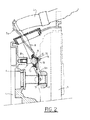
- la figure 2 est une vue en coupe longitudinale de la commande d'embrayage disposée dans un carter de boíte de vitesses ;
- la figure 3 représente des vues en perspective d'une rotule selon l'invention.
On a représenté aux figure 1 et 2, une commande d'embrayage,
notamment pour véhicule automobile, constituée de manière classique
d'un embrayage 1 dont seul la butée 2 est représentée, ledit embrayage
étant prévu entre le moteur non visible sur les figures, et une boíte de
vitesses, représentée par son carter 3.
Cette commande d'embrayage représentée sur les figures est une
commande hydraulique, constitué d'un vérin 4 qui agit sur une extrémité
5a d'un levier à fourchette 5, pivotant sur une articulation 6 solidaire du
carter 3 de boíte de vitesses.
L'autre extrémité 5b du levier 5 est maintenue en contact permanent avec
la butée 2 par l'intermédiaire d'un ressort 7.
L'ensemble du dispositif de commande et son fonctionnement bien connu
en soi ne seront pas décrit plus en détail par la suite de la description.
Selon la présente invention, l'articulation 6 du levier 5 est constituée
d'une articulation rotulante comportant une queue de rotule 8 montée
fixement par l'intermédiaire d'un filetage sur le carter 3 de la boíte de
vitesses formant support de rotule et d'une tête de rotule 9 sensiblement
sphérique qui coopère avec une plaque 10 ou coussinet de rotule munie
en son centre d'une forme complémentaire à la tête de rotule 9 du type
calotte sphérique. Ladite plaque 10 ou coussinet est avantageusement
interposé entre le levier 5 et la tête de rotule 9.
Ce coussinet de rotule 10 est pourvu sur la face 11 en contact avec la tête
de rotule 9 d'un revêtement présentant un très faible coefficient de
friction.
Ce revêtement est constitué par exemple de résine fluorées dans lesquelles
est insérée une trame métallique du type bronze étain..
Selon une variante, le revêtement de la face en contact avec la tête de
rotule est constitué uniquement de résines fluorés du type Téflon.
Le coussinet 10 peut être est également muni en son centre d'un orifice
12, comme visible plus clairement sur la figure 1. Un tel orifice quant il
existe est destiné à la canalisation du fluage du revêtement lors des
sollicitations de l'articulation 6.
Afin d'assurer le maintient du levier 5 sur la tête de rotule 9, un soufflet
d'étanchéité 13 enserrant la tête de rotule 9 est muni d'au moins une
patte de fixation 14 saillant perpendiculairement au soufflet 13 en
direction du levier 5 apte à s'engager et à se clipper dans un orifice 15
correspondant du levier 5.
On notera qu'avantageusement les pattes 14 de fixation du soufflet 13
traversent la plaque 10 ou coussinet notamment par l'intermédiaire de
trou oblong 16 immobilisant ainsi cette dernière en rotation sur le levier 5.
En se reportant sur la figure 3, la rotule selon l'invention y a été détaillée.
La tête de rotule est constituée de deux pièces distinctes 91 et 92 de
formes complémentaires.
La première pièce 91 qui fait corps avec la queue 8 présente une extrémité
évasée se terminant par une face plane 95. Sur cette face plane 95
débouche une empreinte 93 de type Torx permettant le vissage de la rotule
sur son support 3.
La seconde pièce 92 est de forme sensiblement hémisphérique Elle
comporte un téton 94 en saillie sur sa face plane 96. Ce téton 94 de forme
complémentaire à celle de l'empreinte est destiné à pénétrer dans
l'empreinte 93 et assurer ainsi le positionnement de la pièce 92 sur la
pièce 91.
Le soufflet qui vient enserrer la pièce 91 permet alors l'immobilisation de
la pièce 92 contre la pièce 91.
Ainsi grâce à cette disposition l'empreinte 93 n'est plus apparente et n'est
donc plus susceptible de venir endommager le coussinet 10.
Il est par ailleurs à noter que cette disposition peut permettre d'utiliser
des matériaux de nature différente pour la constitution des deux pièces
formant la tête de rotule.
Bien entendu, la présente invention n'est pas limitée au mode de
réalisation que l'on vient de décrire, et on peut apporter à ceux-ci de
nombreux changements et modifications sans sortir de la présente
invention.
Ainsi, bien que l'invention ait été décrite en liaison avec un mode de
réalisation particulier, l'articulation selon l'invention peut s'appliquer à
tout type d'articulation rotulante. Elle comprend également tous les
équivalents techniques des moyens décrits.
Claims (9)
- Articulation rotulante (6) constituée d'une rotule comportant une queue de rotule (8) filetée destinée à venir se visser sur un support (3) et une tête de rotule (9) de forme sensiblement sphérique coopérant avec un organe mobile (5), caractérisée en ce que la tête de rotule est réalisée sous la forme d'une première et d'une seconde pièces distinctes complémentaires (91,92), ladite première pièce (91) présentant une empreinte (93) appropriée permettant le vissage de ladite queue de rotule (8) sur ledit support (3).
- Articulation rotulante (6) selon la revendication 1, caractérisée en ce que ladite tête de rotule (9) est enserrée par un soufflet (13) destiné à être rendu solitaire dudit organe mobile (5).
- Articulation rotulante (6) selon l'une quelconque des revendications 1 à 2, caractérisée en ce que ledit soufflet (13) est rendu solidaire dudit organe (5) par l'intermédiaire d'au moins une patte (14) saillant du soufflet (13) destinée à s'engager et à se clipper dans un orifice correspondant dudit organe (5).
- Articulation rotulante (6) selon l'une quelconque des revendications 1 à 3, caractérisée en ce qu'entre ledit organe (5) et ladite tête de rotule (9) est interposée une plaque (10) dont la face en contact avec ladite tête de rotule (9) est munie d'un revêtement présentant un faible coefficient de frottement.
- Articulation rotulante (6) selon l'une quelconque des revendications 1 à 4, caractérisée en ce que la première pièce (91) s'étend dans le prolongement de ladite queue de rotule (8) avec laquelle elle fait corps et en ce que la seconde pièce (92) est de forme sensiblement hémisphérique.
- Articulation rotulante (6) selon l'une quelconque des revendications 1 à 5, caractérisée en ce que ladite seconde pièce (92) présente un téton adapté (94) faisant saillie, ledit téton (94) étant destiné à venir se loger dans ladite empreinte (93).
- Articulation rotulante (6) selon les revendications 2 et 5, caractérisée en ce que ladite première pièce (91) est enserrée par ledit soufflet (13), ledit soufflet (13) venant forcer ladite seconde pièce (92) contre ladite première pièce (91).
- Articulation rotulante (6) selon l'une quelconque des revendications 1 à 7, caractérisée en ce que lesdites première et seconde pièces (91, 92) sont réalisées dans des matériaux distincts.
- Commande d'embrayage notamment pour véhicule automobile comportant un levier (5) monté pivotant sur une articulation (6) dans sa partie centrale sur un support fixe (3) et dont l'une de ses extrémités (5a) est reliée à un moyen d'actionnement et dont l'autre extrémité (5b) en forme de fourchette coopère avec une butée (2) d'embrayage, caractérisée en ce que l'articulation est une articulation rotulante (6) conforme à l'une quelconque des revendications précédentes.
Applications Claiming Priority (2)
| Application Number | Priority Date | Filing Date | Title |
|---|---|---|---|
| FR0451268A FR2871536B1 (fr) | 2004-06-14 | 2004-06-14 | Articulation rotulante perfectionnee et application d'une telle articulation pour une commande d'embrayage |
| FR0451268 | 2004-06-14 |
Publications (1)
| Publication Number | Publication Date |
|---|---|
| EP1607644A2 true EP1607644A2 (fr) | 2005-12-21 |
Family
ID=34946234
Family Applications (1)
| Application Number | Title | Priority Date | Filing Date |
|---|---|---|---|
| EP20050300427 Withdrawn EP1607644A2 (fr) | 2004-06-14 | 2005-05-30 | Articulation rotulante et application d'une telle articulation pour une commande d'embrayage |
Country Status (2)
| Country | Link |
|---|---|
| EP (1) | EP1607644A2 (fr) |
| FR (1) | FR2871536B1 (fr) |
Cited By (1)
| Publication number | Priority date | Publication date | Assignee | Title |
|---|---|---|---|---|
| WO2011076171A1 (fr) * | 2009-12-22 | 2011-06-30 | Schaeffler Technologies Gmbh & Co. Kg | Système d'actionnement pour un embrayage |
Families Citing this family (1)
| Publication number | Priority date | Publication date | Assignee | Title |
|---|---|---|---|---|
| AU2017243876A1 (en) * | 2016-03-31 | 2018-10-18 | Quest Engineering Pty Ltd | Multi-directional mounting bracket |
Family Cites Families (4)
| Publication number | Priority date | Publication date | Assignee | Title |
|---|---|---|---|---|
| FR1043832A (fr) * | 1950-10-16 | 1953-11-12 | Ehrenreich & Cie A | Pivot à rotule |
| US3429598A (en) * | 1965-10-15 | 1969-02-25 | Moog Industries Inc | Ball joint unit for steerable vehicle wheels |
| JPS4910780B1 (fr) * | 1970-10-13 | 1974-03-13 | ||
| FR2791100B1 (fr) * | 1999-03-17 | 2001-04-13 | Peugeot | Articulation rotulante et l'application d'une telle articulation pour une commande d'embrayage |
-
2004
- 2004-06-14 FR FR0451268A patent/FR2871536B1/fr not_active Expired - Fee Related
-
2005
- 2005-05-30 EP EP20050300427 patent/EP1607644A2/fr not_active Withdrawn
Cited By (3)
| Publication number | Priority date | Publication date | Assignee | Title |
|---|---|---|---|---|
| WO2011076171A1 (fr) * | 2009-12-22 | 2011-06-30 | Schaeffler Technologies Gmbh & Co. Kg | Système d'actionnement pour un embrayage |
| CN102713328A (zh) * | 2009-12-22 | 2012-10-03 | 舍弗勒技术股份两合公司 | 用于离合器的接合系统 |
| CN102713328B (zh) * | 2009-12-22 | 2015-11-25 | 舍弗勒技术股份两合公司 | 用于离合器的接合系统 |
Also Published As
| Publication number | Publication date |
|---|---|
| FR2871536B1 (fr) | 2007-10-05 |
| FR2871536A1 (fr) | 2005-12-16 |
Similar Documents
| Publication | Publication Date | Title |
|---|---|---|
| EP1296413A1 (fr) | Dispositif de raccordement à ressort de connexion manoeuvré par une came | |
| FR2748515A1 (fr) | Charniere a systeme de rappel par anneau elastique | |
| EP0563032B1 (fr) | Charniere a crans de retenue pour une porte, notamment d'un vehicule automobile | |
| EP1423285B1 (fr) | Dispositif de montage d'un capteur sur une jante de roue de vehicule automobile et procede de montage associe | |
| FR2478718A1 (fr) | Dispositif a reglage automatique pour le blocage, en position fermee, d'une porte coulissante d'un vehicule automobile | |
| FR2460818A1 (fr) | Regulateur de pression jumele pour deux circuits de freinage | |
| FR2791100A1 (fr) | Articulation rotulante et l'application d'une telle articulation pour une commande d'embrayage | |
| EP0584018B1 (fr) | Dispositif d'essuie-glace à tête d'entraînement perfectionnée | |
| FR2634263A1 (fr) | Dispositif tendeur de courroie premonte | |
| EP1906034A2 (fr) | Dispositif de liaison rotule entre un levier et une tige d'actionnement | |
| FR2871536A1 (fr) | Articulation rotulante perfectionnee et application d'une telle articulation pour une commande d'embrayage | |
| FR2726803A1 (fr) | Dispositif de montage d'une pedale pour cycles ou vehicules similaires | |
| EP0887092A1 (fr) | Fixation de sécurité de chaussure de ski | |
| FR2810873A1 (fr) | Dispositif de liaison intervertebral | |
| FR2956146A1 (fr) | Serrure pour ouvrant de vehicule automobile | |
| FR2670447A1 (fr) | Dispositif de liaison entre un arbre d'entrainement et un bras d'essuie-glace, notamment pour vehicule automobile. | |
| FR2769037A1 (fr) | Dispositif de verrouillage comportant un doigt de transmission commande par came | |
| FR2786233A1 (fr) | Dispositif de liaison pour levier pivotant, notamment pedale de frein, et organe de commande associe | |
| EP0334755A1 (fr) | Dispositif d'essuie-glace dissimulable destiné à équiper, par exemple, un véhicule automobile | |
| FR3073021B1 (fr) | Ensemble comportant un panneau et un systeme de fixation | |
| FR2899624A1 (fr) | Agencement d'un ouvrant sur un support | |
| FR2948303A1 (fr) | Outil d'application d'un element adhesif sur une surface d'application | |
| EP0349368B1 (fr) | Frein à disque réglable | |
| EP0115779A2 (fr) | Manette d'actionnement pour dérailleur de cycle | |
| FR3106098A1 (fr) | Dispositif d’essuie-glace, adaptateur de balai d’essuie-glace du dispositif d’essuie-glace et essuie-glace avec un dispositif d’essuie-glace |
Legal Events
| Date | Code | Title | Description |
|---|---|---|---|
| PUAI | Public reference made under article 153(3) epc to a published international application that has entered the european phase |
Free format text: ORIGINAL CODE: 0009012 |
|
| AK | Designated contracting states |
Kind code of ref document: A2 Designated state(s): AT BE BG CH CY CZ DE DK EE ES FI FR GB GR HU IE IS IT LI LT LU MC NL PL PT RO SE SI SK TR |
|
| AX | Request for extension of the european patent |
Extension state: AL BA HR LV MK YU |
|
| 17P | Request for examination filed |
Effective date: 20060615 |
|
| STAA | Information on the status of an ep patent application or granted ep patent |
Free format text: STATUS: THE APPLICATION IS DEEMED TO BE WITHDRAWN |
|
| 18D | Application deemed to be withdrawn |
Effective date: 20101201 |