EP1607585A1 - Fatigue failure diagnostic method of turbocharger and fatigue failure diagnostic apparatus for turbocharger - Google Patents
Fatigue failure diagnostic method of turbocharger and fatigue failure diagnostic apparatus for turbocharger Download PDFInfo
- Publication number
- EP1607585A1 EP1607585A1 EP05011760A EP05011760A EP1607585A1 EP 1607585 A1 EP1607585 A1 EP 1607585A1 EP 05011760 A EP05011760 A EP 05011760A EP 05011760 A EP05011760 A EP 05011760A EP 1607585 A1 EP1607585 A1 EP 1607585A1
- Authority
- EP
- European Patent Office
- Prior art keywords
- revolution speed
- fatigue
- peak point
- stress
- turbocharger
- Prior art date
- Legal status (The legal status is an assumption and is not a legal conclusion. Google has not performed a legal analysis and makes no representation as to the accuracy of the status listed.)
- Granted
Links
- 238000002405 diagnostic procedure Methods 0.000 title claims description 13
- 238000005259 measurement Methods 0.000 claims description 12
- 238000006467 substitution reaction Methods 0.000 claims description 6
- 238000000034 method Methods 0.000 abstract description 10
- 238000012545 processing Methods 0.000 description 11
- 230000001133 acceleration Effects 0.000 description 7
- 239000011159 matrix material Substances 0.000 description 7
- 230000010354 integration Effects 0.000 description 4
- 238000010586 diagram Methods 0.000 description 2
- 230000000694 effects Effects 0.000 description 2
- 238000012360 testing method Methods 0.000 description 2
- 101100421778 Arabidopsis thaliana SNL2 gene Proteins 0.000 description 1
- 238000007796 conventional method Methods 0.000 description 1
- 238000001514 detection method Methods 0.000 description 1
- 238000011156 evaluation Methods 0.000 description 1
- 238000002474 experimental method Methods 0.000 description 1
- 239000000463 material Substances 0.000 description 1
- 238000012986 modification Methods 0.000 description 1
- 230000004048 modification Effects 0.000 description 1
Images


Classifications
-
- F—MECHANICAL ENGINEERING; LIGHTING; HEATING; WEAPONS; BLASTING
- F04—POSITIVE - DISPLACEMENT MACHINES FOR LIQUIDS; PUMPS FOR LIQUIDS OR ELASTIC FLUIDS
- F04D—NON-POSITIVE-DISPLACEMENT PUMPS
- F04D27/00—Control, e.g. regulation, of pumps, pumping installations or pumping systems specially adapted for elastic fluids
- F04D27/02—Surge control
- F04D27/0292—Stop safety or alarm devices, e.g. stop-and-go control; Disposition of check-valves
-
- F—MECHANICAL ENGINEERING; LIGHTING; HEATING; WEAPONS; BLASTING
- F02—COMBUSTION ENGINES; HOT-GAS OR COMBUSTION-PRODUCT ENGINE PLANTS
- F02B—INTERNAL-COMBUSTION PISTON ENGINES; COMBUSTION ENGINES IN GENERAL
- F02B39/00—Component parts, details, or accessories relating to, driven charging or scavenging pumps, not provided for in groups F02B33/00 - F02B37/00
- F02B39/16—Other safety measures for, or other control of, pumps
-
- F—MECHANICAL ENGINEERING; LIGHTING; HEATING; WEAPONS; BLASTING
- F04—POSITIVE - DISPLACEMENT MACHINES FOR LIQUIDS; PUMPS FOR LIQUIDS OR ELASTIC FLUIDS
- F04D—NON-POSITIVE-DISPLACEMENT PUMPS
- F04D27/00—Control, e.g. regulation, of pumps, pumping installations or pumping systems specially adapted for elastic fluids
- F04D27/001—Testing thereof; Determination or simulation of flow characteristics; Stall or surge detection, e.g. condition monitoring
-
- F—MECHANICAL ENGINEERING; LIGHTING; HEATING; WEAPONS; BLASTING
- F05—INDEXING SCHEMES RELATING TO ENGINES OR PUMPS IN VARIOUS SUBCLASSES OF CLASSES F01-F04
- F05D—INDEXING SCHEME FOR ASPECTS RELATING TO NON-POSITIVE-DISPLACEMENT MACHINES OR ENGINES, GAS-TURBINES OR JET-PROPULSION PLANTS
- F05D2220/00—Application
- F05D2220/40—Application in turbochargers
Definitions
- the present invention relates to fatigue failure diagnostic method and apparatus for a turbocharger mounted on an engine.
- a turbocharger (supercharger) comprises a turbine connected to the exhaust gas channel of an engine and driven by the exhaust gas of the engine and a compressor connected to the intake channel of the engine and driven by the turbine.
- the turbine comprises a turbine wheel fixedly mounted on a rotary shaft.
- the compressor comprises a compressor impeller fixedly mounted on the same rotary shaft as the turbine wheel.
- the compressor impeller located on the same rotary shaft is rotated by rotating the turbine wheel with the exhaust gas of the engine.
- the compressor intakes the air and the pressure of the intake air is increased. Further, the intake air under increased pressure is supplied to the engine.
- the compressor impeller of the turbocharger rotates at a very high speed, a comparatively large load is applied to the compressor impeller. If the compressor impeller is fractured, the fractured pieces thereof can be sucked into the engine. For this reason the replacement period of the compressor impeller is determined in advance and the compressor is replaced after each such replacement period.
- the degree of fatigue in particular, LCF (Low Cycle Fatigue)
- the replacement period was determined based on the estimation results.
- the estimation of fatigue was conducted based on the test data on the revolution speed of the compressor impeller that assumed the operation state of the engine.
- Japanese Patent Application Laid-open No. 2001-329856 described a method for diagnosing the fatigue of a gas turbine.
- This method comprises the steps of measuring pressure fluctuations at the blade stage of a gas turbine compressor, conducting stress analysis by using the measured pressure fluctuation data and structure analysis model of the compressor blades and estimating the stress fluctuations in the actual operation environment of the compressor blades, comparing the stress fluctuations of the compressor blades that were thus estimated with the strength master curve under corrosive environment of the compressor blade material, evaluating the fatigue damage of the compressor blades, and determining the replacement period of the compressor blades based on the evaluated fatigue damage.
- the present invention was created with the foregoing in view and it is an object thereof to enable the judgment of the degree of turbocharger fatigue corresponding to the actual operation state of the engine and to evaluate the adequate replacement period of the turbocharger.
- a fatigue failure diagnostic method of a turbocharger for diagno sing the fatigue failure of a turbocharger comprising the steps of measuring the revolution speed of the turbocharger, computing an accumulated fatigue value based on the measured revolution speed, and executing the fatigue failure judgment of the turbocharger by comparing the computed accumulated fatigue value and the prescribed fatigue limit value.
- This fatigue failure diagnostic method of a turbocharger comprises a step of finding in advance the relationship between a stress amplitude at the time a stress of constant amplitude is periodically and cyclically applied to the turbocharger till it is fatigue fractured and a stress variation cycle number at this time, wherein the fatigue failure judgment is conducted each time a peak point of revolution fluctuation is judged based on the measured revolution speed, and the computation of the accumulated fatigue value comprises a step of reading the revolution speed in the peak point that was judged and substituting this revolution speed into the peak point revolution speed, a step of computing a peak point stress by using this peak point revolution speed, a step of computing the stress fluctuation width from the previous peak point by using this peak point stress and the peak point stress in the previous peak point, a step of substituting this stress fluctuation width into the stress amplitude and retrieving the stress variation cycle number corresponding to this stress amplitude from the relationship, a step of calculating a fatigue value by using the retrieved stress variation cycle number and conducting the prescribed computations, and a step of
- this fatigue failure diagnostic method of a turbocharger comprises a step of finding in advance the relationship between a maximum peak revolution speed at the time the revolution speed of the turbocharger is periodically and cyclically changed till the turbocharger is fatigue fractured, a revolution speed amplitude at this time, and a revolution speed variation cycle number at this time, wherein the fatigue failure judgment is conducted each time a peak point of revolution fluctuation is judged based on the measured revolution speed, and the computation of the accumulated fatigue value comprises a step of reading the revolution speed in the peak point that was judged and substituting this revolution speed into the peak point revolution speed, a step of computing the revolution speed fluctuation width from the previous peak point by using this peak point revolution speed and the peak point revolution speed in the previous peak point, a step of substituting the peak point revolution speed into the maximum peak revolution speed, substituting the computed revolution speed fluctuation width into the revolution speed amplitude, and retrieving the revolution speed variation cycle number corresponding to those maximum peak revolution speed and revolution speed amplitude from the relationship, a step of calculating a
- the calculation of the fatigue value comprise calculating the inverse number of the retrieved stress variation cycle number and taking it as the fatigue value.
- the computation of the accumulated fatigue value comprise adding the calculated fatigue value to the accumulated fatigue value computed in the previous peak point and taking it as the accumulated fatigue value.
- a fatigue failure diagnostic apparatus for a turbocharger for diagnosing the fatigue failure of a turbocharger comprising revolution speed measurement means for measuring the revolution speed of the turbocharger, computation means for computing an accumulated fatigue value based on the revolution speed measured with the revolution speed measurement means, and judgment means for executing the fatigue failure judgment of the turbocharger by comparing the accumulated fatigue value computed with the computation means and the prescribed fatigue limit value.
- This fatigue failure diagnostic apparatus for a turbocharger comprises storage means for storing the relationship between a stress amplitude at the time a stress of constant amplitude is periodically and cyclically applied to the turbocharger till it is fatigue fractured and a stress variation cycle number at this time, wherein the fatigue failure judgment is conducted each time a peak point of revolution fluctuation is judged based on the revolution speed measured with the revolution speed measurement means, and the computation means comprises peak point revolution speed substitution means for reading the revolution speed in the peak point that was judged and substituting this revolution speed into the peak point revolution speed, peak point stress computation means for computing a peak point stress by using this peak point revolution speed, stress fluctuation width computation means for computing the stress fluctuation width from the previous peak point by using this peak point stress and the peak point stress in the previous peak point, cycle number retrieval means for substituting this stress fluctuation width into the stress amplitude and retrieving the stress variation cycle number corresponding to this stress amplitude from the relationship, fatigue value calculation means for calculating the fatigue value by using the stress variation cycle number retrieved with the cycle
- this fatigue failure diagnostic apparatus for a turbocharger comprises storage means for storing the relationship between a maximum peak revolution speed at the time the revolution speed of the turbocharger is periodically and cyclically changed till the turbocharger is fatigue fractured, a revolution speed amplitude at this time, and a revolution speed variation cycle number at this time, wherein the fatigue failure judgment is conducted each time a peak point of revolution fluctuation is judged based on the revolution speed measured with the revolution speed measurement means, and the computation means comprises peak point revolution speed substitution means for reading the revolution speed in the peak point that was judged and substituting this revolution speed into the peak point revolution speed, revolution speed fluctuation width computation means for computing the revolution speed fluctuation width from the previous peak point by using this peak point revolution speed and the peak point revolution speed in the previous peak point, cycle number retrieval means for substituting the peak point revolution speed into the maximum peak revolution speed, substituting the revolution speed fluctuation width computed with the revolution speed fluctuation width computation means in the revolution speed amplitude, and retrieving the revolution speed variation cycle number corresponding to those maximum peak revolution speed and
- the computation of the fatigue value comprise calculating the inverse number of the retrieved stress variation cycle number and taking it as the fatigue value.
- the computation of the accumulated fatigue value comprise adding the calculated fatigue value to the accumulated fatigue value computed in the previous peak point and taking it as the accumulated fatigue value.
- the judgment means further comprises alarm means actuated when the fatigue failure of the turbocharger was judged to take place by the fatigue failure judgment means.
- FIG. 1 is a schematic view of the engine employing the fatigue failure diagnostic apparatus for a turbocharger of the first preferred embodiment of the present invention.
- FIG. 2 is a map having a stress amplitude - stress variation cycle number line.
- FIG. 3 is a time - revolution speed diagram representing changes in the revolution speed with time.
- FIG. 4 is a flowchart of processing conductive with the ECU of the first embodiment.
- FIG. 5 is a table having maximum peak revolution number - revolution number amplitude matrix.
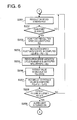
- FIG. 6. is a flowchart of processing conducted with the ECU of the second embodiment.
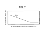
- FIG. 7 is a map having a stress amplitude - stress variation cycle number line of a modification example.
- FIG. 1 is a schematic view of the engine employing the fatigue failure diagnostics apparatus for a turbocharger of the first preferred embodiment of the present invention.
- the engine of the present embodiment is a diesel engine installed on vehicles such as trucks or cars.
- the reference numeral 1 stands for an engine body, 2 - an intake channel provided in the engine body 1 and serving to pass an intake air, 3 - an exhaust channel provided in the engine body 1 and serving to pass an exhaust gas, 4 - a control unit (referred to hereinbelow as ECU) to which a variety of sensors and devices are connected, and 5 - a turbocharger mounted on the engine body 1.
- ECU control unit
- the turbocharger 5 of the present embodiment comprises a turbine 6 connected to the exhaust channel 3 and driven by the exhaust gas of the engine body 1 and a compressor 7 connected to the intake channel 2 and driven by the turbine 6.
- a bearing 8 is provided between the turbine 6 and compressor 7. The bearing 8 rotatably supports the shaft (rotary shaft) 9.
- the turbine 6 comprises a turbine housing 10 and a turbine wheel 11 provided inside the turbine housing 10 and fixed to one end section of the shaft 9.
- the compressor 7 comprises a compressor housing 12 and a compressor impeller 13 provided inside the compressor housing 12 and fixed to the other end section of the shaft 9. In other words, the turbine wheel 11 and compressor impeller 13 are disposed on the same shaft (shaft 9).
- the turbine wheel 11 If the exhaust gas of the engine body 1 is supplied to the turbine wheel 11, the turbine wheel 11 is rotated. As a result, the turbine 6 is rotated. If the turbine 6 is rotated, the compressor impeller 13 disposed on the same shaft as the turbine wheel 11 is also rotated. As a result, the compressor 7 is driven.
- the compressor 7 takes the air into the compressor housing 12, and the pressure of this intake air is increased inside the compressor housing 12. This air under increased pressure is supplied by the compressor 7 to the engine body 1.
- the turbocharger 5 of the present embodiment comprises an apparatus for diagnosing the fatigue failure of the turbocharger 5.
- the fatigue failure diagnostic apparatus of the present embodiment is designed for diagnosing the fatigue failure of the compressor impeller 13.
- the fatigue failure diagnostic apparatus of the present embodiment comprises revolution speed measurement means for measuring the revolution speed of the compressor impeller 13.
- the revolution speed measurement means of the present embodiment comprises a revolution speed sensor 14 provided in the compressor housing 12 and an ECU 4.
- the revolution speed sensor 14 is connected to the ECU 4, and a detection signal from the revolution speed sensor 14 is inputted in the ECU 4.
- the revolution speed is the number of revolutions (rotation speed) in 1 min.
- the fatigue failure diagnostic apparatus of the present embodiment comprises computation means for computing the accumulated fatigue value based on the revolution speed of the compressor impeller 13 measured with the aforementioned revolution speed measurement means and judgment means for executing the fatigue failure judgment of the compressor impeller 13 by comparing the accumulated fatigue value computed by the computation means with the prescribed fatigue limit value.
- the ECU 4 of the present embodiment manages the computation means and judgment means.
- the accumulated fatigue value is a value indicating the degree of fatigue accumulated in the compressor impeller 13.
- the fatigue failure diagnostic apparatus of the present embodiment comprises alarm means actuated when the judgment means makes a decision that the fatigue failure of the compressor impeller 13 took place (replacement is necessary).
- the actuation of the alarm means calls upon the user (for example, the operator) to replace the compressor impeller 13.
- the alarm means of the present embodiment comprises an alarm lamp 15 disposed on the meter panel (not shown in the figures) of the operation room and the ECU 4.
- the alarm lamp 15 is connected to the ECU 4.
- the actuation of the alarm lamp 15 (turned off, turned on, or turned on-off) is controlled by the ECU 4.
- the alarm lamp 15 is turned off in the usual state and turned on and emits red light in the case of alarm.
- the ECU 4 serving as storage means stores the relationship between a stress amplitude SLt at the time a stress of constant amplitude (centrifugal stress) was periodically and cyclically applied to the compressor impeller 13 till it was fatigue fractured and a stress variation cycle number SNF (till fatigue fracture) at this time.
- a centrifugal stress is applied to the compressor 13
- the revolution speed with a constant amplitude corresponding to this centrifugal stress is periodically and cyclically changed.
- the aforementioned relationship is found in advance for a location in the compressor impeller 13 where fatigue failure can be expected. Further, where there are multiple locations in the compressor impeller 13 where the fatigue failure is expected, the relationship is found in advance for each such location.
- this relationship is represented by a stress amplitude - stress variation cycle number line SNL shown in FIG. 2.
- a map having the stress amplitude - stress variation cycle number line SNL is stored in the ECU 4.
- the stress amplitude - stress variation cycle number line SNL in the present embodiment is the so-called S-N curve (Stress-Number Curve) found experimentally or analytically.
- the aforementioned relationship may be also represented by a numerical formula.
- the fatigue failure diagnostic of the compressor impeller 13 is conducted by the ECU 4. This diagnostic will be explained with reference to FIG. 3 and FIG. 4.
- FIG. 3 is a time - revolution speed diagram representing changes in the revolution speed with time.
- the waveform W is obtained by deducting components ineffective for the fatigue failure diagnostic (for example, noise or very small fluctuations of revolution speed) by filter processing from the base waveform measured with the revolution speed sensor 14.
- FIG. 4 is a flowchart of processing conducted by the ECU of the first embodiment.
- step S101 the ECU 4 measures the revolution speed of the compressor impeller 13 by detecting the signals from the revolution speed sensor 14.
- the ECU 4 judges the peak points of the revolution fluctuations based on the revolution speed measured in step S101.
- the fatigue failure decision is made each time a peak point of revolution fluctuation is judged based on the measured revolution speed.
- the peak point (see the reference symbol P(i) etc. in FIG. 3) is a point of switching between positive and negative acceleration (point of switching between acceleration and deceleration), and the revolution fluctuation is the difference in the revolution speed between two adjacent peak points. Furthermore, in the present embodiment, when the acceleration is constant(0), it is not a peak point.
- "i" in the reference numeral P(i) represents any cycle of revolution fluctuations (the same is true for "i" in the reference symbols below).
- step S103 the ECU 4 reads the revolution speed in the peak point judged in step S102 and substitutes this revolution speed into the peak point revolution speed R(i).
- step S104 the ECU 4 computes a peak point stress SP(i) acting upon the compressor impeller 13 by using the peak point revolution speed R(i) substituted in step S103.
- the computation of the peak point stress SP(i) involves the calculation of centrifugal stress based on the finite element method (FEM).
- FEM finite element method
- the relationship between the peak point revolution speed R(i) and peak point stress SP(i) corresponding thereto may be represented in the form of a graph or a numerical formula and may be stored in this form in the ECU 4.
- step S105 the ECU 4 computes the stress fluctuation width SL(i) from the previous peak point by using the peak point stress SP(i) computed in step S104 and the peak point stress SP(i-1) in the previous peak point.
- peak point stress SP(i-1) in the previous peak point is deducted from the peak point stress SP(i) and the absolute value of the result obtained is considered as the stress fluctuation width SL(i).
- step S106 the ECU 4 substitutes the stress fluctuation width SL(i) computed in step S105 into the stress amplitude SLt(i) of FIG. 2, and retrieves the stress variation cycle number SNFt(i) shown in FIG. 2 and corresponding to the stress amplitude SLt(i) from the stress amplitude - stress variation cycle number SNL.
- the stress variation cycle number SNFt is represented by 10 5 cycles.
- the stress amplitude SLt is less than the fatigue limit (shown by the reference symbol EL in FIG. 2)
- the stress variation cycle number SNFt at this time is taken as ⁇ .
- the stress variation cycle number SNFt(i) is substituted into the number of cycles NF(i) of rotation fluctuations.
- the retrieval from the above-described relationship stress amplitude - stress variation cycle number SNL involves multipoint interpolation read system (for example, four-point interpolation) or gradient reading system, in addition to retrieval for each revolution fluctuation.
- the ECU 4 conducts the prescribed computations by using the number of cycles NF(i) retrieved and substituted in step S106 and calculates the fatigue value F(i) of the compressor impeller 13 corresponding to the revolution fluctuation.
- the calculation of the fatigue value F(i) comprises calculating the inverse number of the number of cycles NF(i) and taking it as the fatigue value F(i). for example, if the number of cycles NF(i) is 10 5 , the fatigue value F(i) will be 0.00001. Here, if the number of cycles NF(i) is ⁇ , the fatigue value F(i) will be 0 (1/ ⁇ ). Further, it is preferred that the calculation of the fatigue value F(i) be based on the high-temperature fatigue strength. For example, a temperature sensor is provided in the compressor housing 12 and the temperature compensation is conducted based on the temperature measured therewith.
- step S108 the ECU 4 computes the accumulated fatigue value Ft(i) of revolution fluctuations by using the fatigue value F(i) calculated in step S107 and the accumulated fatigue value Ft(i-1) computed in the previous peak point.
- the fatigue value F(i) is added to the accumulated fatigue value Ft(i-1) computed in the previous peak point and the result is taken as a new accumulated fatigue value Ft(i).
- the fatigue value Ft(i) of the compressor impeller 13 corresponding to the revolution fluctuations is integrated according to the Miner's rule.
- the integration method may be not only a simple integration, but also a highly accurate rain-flow method.
- step S109 the ECU 4 executes the fatigue failure judgment of the compressor impeller 13 by comparing the accumulated fatigue value Ft(i) computed in step S108 with the prescribed fatigue limit value F1.
- the judgment criterion of the fatigue failure is such that the fatigue failure is judged to take place when the accumulated fatigue value Ft(i) is equal to or higher than the fatigue limit value F1. If the accumulated fatigue value Ft reaches 1.0, the stress variation cycle number SNFt is apparently reached. Therefore, it is preferred that the fatigue limit value F1 be set lower than 1.0 (for example, 0.9 or 0.8).
- step S110 the ECU 4 actuates the above-described alarm means and the user is informed that it is timely to replace the compressor impeller 13.
- the actuation of the alarm means comprises turning on the alarm lamp 15 with the ECU 4.
- step S109 when the ECU 4 did not judge the peak point in step S102 or the fatigue failure was not judged to take place in step S109, the processing flow returns to step S101 and the ECU 4 again conducts the processing from step S101.
- the accumulated fatigue value Ft is computed for each such location and the fatigue failure judgment is executed for each location by comparing those accumulated fatigue value Ft and each fatigue limit value F1 according to the above-described procedure.
- the ECU 4 of the present embodiment comprises the peak point revolution speed substitution means, peak point stress computation means, stress fluctuation width computation means, cycle number retrieval means, fatigue value calculation means, and accumulated fatigue value computation means of the claims.
- the above-described fatigue failure diagnostic method of a turbocharger of the present embodiment comprises the steps of measuring the revolution speed of the turbocharger 5, computing an accumulated fatigue value Ft based on the measured revolution speed, and executing the fatigue failure judgment of the turbocharger 5 by comparing the computed accumulated fatigue value Ft and the prescribed fatigue limit value F1.
- the operation state of the turbocharger 5 is monitored by measuring the revolution speed of the turbocharger 5 and executing the fatigue failure diagnostic of the turbocharger 5 based thereupon. Therefore, with the present embodiment, the degree of fatigue of the turbocharger 5 corresponding to the actual operation state of the engine can be judged and the adequate replacement period of the turbocharger 5 can be evaluated.
- the sequence of fatigue failure judgment with the ECU 4 is partly different from that of the first embodiment.
- the fatigue failure diagnostic apparatus of this embodiment is also designed for diagnosing the fatigue failure of the compressor impeller 13.
- the ECU 4 serving as storage means stores the relationship between a maximum peak revolution speed Rt at the time the revolution speed of the compressor impeller 13 was periodically and cyclically changed till the turbocharger 13 was fatigue fractured, a revolution speed amplitude Lt at this time, and a revolution speed variation cycle number RNFt at this time (till fatigue fracture).
- This relationship is found in advance for a location in the compressor impeller 13 where fatigue failure can be expected. Further, when there are multiple locations in the compressor impeller 13 where the fatigue failure is expected, the relationship is found in advance for each such location.
- this relationship is represented by a maximum peak revolution speed - revolution speed amplitude matrix RNM shown in FIG. 5.
- This maximum peak revolution speed - revolution speed amplitude matrix RNM is stored in the ECU 4.
- the maximum peak revolution speed - revolution speed amplitude matrix RNM in the present embodiment is found experimentally or analytically.
- the maximum peak revolution speed Rt and revolution speed amplitude Lt in the maximum peak revolution speed - revolution speed amplitude matrix RNM are partitioned into respective prescribed ranges. Those ranges can be set arbitrarily.
- the aforementioned relationship may be also represented by a numerical formula.
- FIG. 6 is a flowchart of processing conducted by the ECU 4 of the second embodiment.
- step S201 the ECU 4 measures the revolution speed of the compressor impeller 13 by detecting the signals from the revolution speed sensor 14.
- step S202 the ECU 4 judges the peak points of the revolution fluctuations based on the revolution speed measured in step 201.
- the fatigue failure decision is made each time a peak point of revolution fluctuation is judged based on the measured revolution speed.
- the peak point (see the reference symbol P(i) etc. in FIG. 3) is a point of switching between positive and negative acceleration (point of switching between acceleration and deceleration), and the revolution fluctuation is the difference in the revolution speed between two adjacent peak points. Furthermore, in the present embodiment, too, when the acceleration is constant (0), it is not a peak point.
- step S203 the ECU 4 reads the revolution speed in the peak point judged in step S202 and substitutes this revolution speed into the peak point revolution speed R(i).
- step S204 the ECU 4 computes a revolution speed fluctuation width L(i) from the previous peak point by using the peak point revolution speed R(i) substituted in step S203 and the peak point revolution speed R(i-1) in the previous peak point.
- the computation of the revolution speed fluctuation width L(i) is conducted by subtracting the peak point revolution speed R(i-1) in the previous peak point from the peak point revolution speed R(i) and taking the absolute value of the result as the revolution speed fluctuation width L(i).
- step S205 the ECU 4 compares the peak point revolution speed R(i) substituted in step S203 with the peak point revolution speed R(i-1) in the previous peak point, substitutes the larger of the two in the maximum peak revolution speed Rt(i) shown in FIG. 5, substitutes the revolution speed fluctuation width L(i) computed in step S204 in the revolution speed amplitude Lt(i) shown in FIG. 5, and retrieves from the maximum peak revolution speed - revolution speed amplitude matrix RNM the revolution speed variation cycle number RNFt shown in FIG. 5 and corresponding to those maximum peak revolution speed Rt(i) and revolution speed amplitude Lt(i).
- the revolution speed variation cycle number RNFt is represented by 10 5 cycles.
- the revolution speed variation cycle number RNFt at this time is represented by ⁇ cycles.
- the revolution speed variation cycle number RNFt is substituted into the number of cycles NF(i) of rotation fluctuations.
- the retrieval from the above-described relationship involves a multipoint interpolation read system (for example, four-point interpolation read system) or a gradient reading system, in addition to retrieval for each revolution fluctuation.
- the ECU 4 conducts the prescribed computations by using the number of cycles NF(i) retrieved and substituted in step S205 and calculates the fatigue value F(i) of the compressor impeller 13 corresponding to the revolution fluctuation.
- the calculation of the fatigue value F(i) comprises calculating the inverse number of the number of cycles NF(i) and taking it as the fatigue value F(i). For example, if the number of cycles NF(i) is 10 5 , the fatigue value F(i) will be 0.00001. Here, if the number of cycles NF(i) is ⁇ , the fatigue value F(i) will be 0 (1/ ⁇ ). Further, it is preferred that the calculation of the fatigue value F(i) be based on the high-temperature fatigue strength.
- step S207 the ECU 4 computes the accumulated fatigue value Ft(i) of revolution fluctuations by using the fatigue value F(i) calculated in step S206 and the accumulated fatigue value Ft(i-1) computed in the previous peak point.
- the fatigue value F(i) is added to the accumulated fatigue value Ft(i-1) computed in the previous peak point and the result is taken as a new accumulated fatigue value Ft(i).
- the fatigue value Ft(i) of the compressor impeller 13 corresponding to the revolution fluctuations is integrated.
- the integration method may be not only a simple integration, but also a highly accurate rain-flow method.
- step S208 the ECU 4 executes the fatigue failure judgment of the compressor impeller 13 by comparing the accumulated fatigue value Ft(i) computed in step S207 with the prescribed fatigue limit value F1.
- the judgment criterion of the fatigue failure is such that the fatigue failure is judged to take place when the accumulated fatigue value Ft(i) is equal to or higher than the fatigue limit value F1. If the accumulated fatigue value Ft reaches 1.0, revolution speed variation cycle number RNFt is apparently reached. Therefore, it is preferred than the fatigue limit value F1 be set lower than 1.0 (for example, 0.9 or 0.8).
- step S209 the ECU 4 actuates the above-described alarm means and the user is informed that it is timely to replace the compressor impeller 13.
- the actuation of the alarm means comprises turning on the alarm lamp 15.
- step S208 when the ECU 4 did not judge the peak point in step S202 or the fatigue failure was not judged to take place in step S208, the processing flow returns to step S201 and the ECU 4 again conducts the processing from step S201.
- the accumulated fatigue value Ft is computed for each such location and the fatigue failure judgment is executed for each location by comparing those accumulated fatigue value Ft and each fatigue limit value F1 according to the above-described procedure.
- the ECU 4 of the present embodiment comprises the peak point revolution speed substitution means, revolution speed fluctuation width computation means, cycle number retrieval means, fatigue value calculation means, and accumulated fatigue value computation means of the claims.
- the diagnostic of fatigue failure was conducted with respect to the compressor impeller 13, but the fatigue failure diagnostic may be also conducted with respect to the shaft 9 or turbine wheel 11.
- the relationship between a stress amplitude at the time a stress of constant amplitude (torsional stress with respect to the shaft 9 and centrifugal stress with respect to the turbine wheel 11) was periodically and cyclically applied to the shaft 9 or turbine wheel 11 till it was fatigue fractured and a stress variation cycle number at this time, or the relationship between a maximum peak revolution speed at the time the revolution speed of the shaft 9 or turbine wheel 11 was periodically and cyclically changed till the shaft 9 or turbine wheel 11 was fatigue fractured, a revolution speed amplitude at this time, and a revolution speed variation cycle number at this time is found in advance and this relationship is stored in the ECU 4.
- the revolution speed of the compressor impeller 13 is equal to the revolution speed of the shaft 9 and turbine wheel 11, the revolution speed measurement means can be identical to that of the above-described embodiments.
- the relationship between a stress amplitude SLt at the time a stress of constant amplitude was periodically and cyclically applied to the compressor impeller 13 till it was fatigue fractured and a stress variation cycle number SNFt at this time may be represented by the stress amplitude - stress variation cycle number line SNL2 obtained by linear approximation, as shown in FIG. 7, of the S-N curve found by tests or analysis.
- the fatigue failure may be also judged by deducting the computed accumulated fatigue value Ft from the prescribed fatigue limit value F1 and judging that the fatigue failure took place when the fatigue limit value F1 becomes 0.
- the alarm means may be an alarm buzzer or the like.
- the aforementioned revolution speed sensor may be provided on the center housing (bearing) or turbine housing. This is because the revolution speed of the compressor impeller is equal to the revolutions peed of the shaft and turbine wheel.
- the engines where the present invention can be employed are not limited to engines for vehicles and may be engines for ships or stationary power generators.
- the engines where the present invention can be employed are not limited to diesel engines and also may be the gasoline engines.
- the fatigue failure diagnostic apparatus for a turbocharger of the present embodiments demonstrates an excellent effect of enabling the judgment of the degree of turbocharger fatigue corresponding to the actual operation state of the engine and evaluation of the adequate replacement period of the turbocharger.
Landscapes
- Engineering & Computer Science (AREA)
- Mechanical Engineering (AREA)
- General Engineering & Computer Science (AREA)
- Chemical & Material Sciences (AREA)
- Combustion & Propulsion (AREA)
- Supercharger (AREA)
- Structures Of Non-Positive Displacement Pumps (AREA)
- Testing Of Engines (AREA)
- Turbine Rotor Nozzle Sealing (AREA)
- Control Of Positive-Displacement Air Blowers (AREA)
Abstract
Description
Claims (13)
- A fatigue failure diagnostic method of a turbocharger for diagnosing the fatigue failure of a turbocharger, comprising the steps of: measuring the revolution speed of the turbocharger; computing an accumulated fatigue value based on the measured revolution speed; and executing the fatigue failure judgment of the turbocharger by comparing the computed accumulated fatigue value and the prescribed fatigue limit value.
- The fatigue failure diagnostic method of a turbocharger according to claim 1, comprising a step of finding in advance the relationship between a stress amplitude at the time a stress of constant amplitude is periodically and cyclically applied to the turbocharger till it is fatigue fractured and a stress variation cycle number at this time, characterized in that the fatigue failure judgment is conducted each time a peak point of revolution fluctuation is judged based on the measured revolution speed, and
the computation of the accumulated fatigue value comprises: a step of reading the revolution speed in the peak point that was judged and substituting this revolution speed into the peak point revolution speed; a step of computing a peak point stress by using this peak point revolution speed; a step of computing the stress fluctuation width from the previous peak point by using this peak point stress and the peak point stress in the previous peak point; a step of substituting this stress fluctuation width into the stress amplitude and retrieving the stress variation cycle number corresponding to this stress amplitude from the relationship; a step of calculating a fatigue value by using the retrieved stress variation cycle number and conducting the prescribed computations; and a step of computing the accumulated fatigue value by using the calculated fatigue value and the accumulated fatigue value computed in the previous peak point. - The fatigue failure diagnostic method of a turbocharger according to claim 1, comprising a step of finding in advance the relationship between a maximum peak revolution speed at the time the revolution speed of the turbocharger is periodically and cyclically changed till the turbocharger is fatigue fractured, a revolution speed amplitude at this time, and a revolution speed variation cycle number at this time, characterized in that the fatigue failure judgment is conducted each time a peak point of revolution fluctuation is judged based on the measured revolution speed, and
the computation of the accumulated fatigue value comprises: a step of reading the revolution speed in the peak point that was judged and substituting this revolution speed into the peak point revolution speed; a step of computing the revolution speed fluctuation width from the previous peak point by using this peak point revolution speed and the peak point revolution speed in the previous peak point; a step of substituting the peak point revolution speed into the maximum peak revolution speed, substituting the computed revolution speed fluctuation width into the revolution speed amplitude, and retrieving the revolution speed variation cycle number corresponding to those maximum peak revolution speed and revolution speed amplitude from the relationship; a step of calculating a fatigue value by using the retrieved revolution speed variation cycle number and conducting the prescribed computations; and a step of computing the accumulated fatigue value by using the calculated fatigue value and the accumulated fatigue value computed in the previous peak point. - The fatigue failure diagnostic method of a turbocharger according to claim 2, characterized in that the calculation of the fatigue value comprises calculating the inverse number of the retrieved stress variation cycle number and taking it as the fatigue value.
- The fatigue failure diagnostic method of a turbocharger according to claim 3, characterized in that the calculation of the fatigue value comprises calculating the inverse number of the retrieved revolution speed variation cycle number and taking it as the fatigue value.
- The fatigue failure diagnostic method of a turbocharger according to one of the claims 2 to 5, characterized in that the computation of the accumulated fatigue value comprises adding the calculated fatigue value to the accumulated fatigue value computed in the previous peak point and taking it as the accumulated fatigue value.
- A fatigue failure diagnostic apparatus for a turbocharger for diagnosing the fatigue failure of a turbocharger, comprising: revolution speed measurement means for measuring the revolution speed of the turbocharger; computation means for computing an accumulated fatigue value based on the revolution speed measured with the revolution speed measurement means; and judgment means for executing the fatigue failure judgment of the turbocharger by comparing the accumulated fatigue value computed with the computation means and the prescribed fatigue limit value.
- The fatigue failure diagnostic apparatus for a turbocharger according to claim 7, comprising storage means for storing the relationship between a stress amplitude at the time a stress of constant amplitude is periodically and cyclically applied to the turbocharger till it is fatigue fractured and a stress variation cycle number at this time, characterized in that the fatigue failure judgment is conducted each time a peak point of revolution fluctuation is judged based on the revolution speed measured with the revolution speed measurement means, and
the computation means comprises: peak point revolution speed substitution means for reading the revolution speed in the peak point that was judged and substituting this revolution speed into the peak point revolution speed; peak point stress computation means for computing a peak point stress by using this peak point revolution speed; stress fluctuation width computation means for computing the stress fluctuation width from the previous peak point by using this peak point stress and the peak point stress in the previous peak point; cycle number retrieval means for substituting this stress fluctuation width into the stress amplitude and retrieving the stress variation cycle number corresponding to this stress amplitude from the relationship; fatigue value calculation means for calculating the fatigue value by using the stress variation cycle number retrieved with the cycle number retrieval means and conducting the prescribed computations; and accumulated fatigue value computation means for computing the accumulated fatigue value by using the fatigue value calculated with the fatigue value calculation means and the accumulated fatigue value computed in the previous peak point. - The fatigue failure diagnostic apparatus for a turbocharger according to claim 7, comprising storage means for storing the relationship between a maximum peak revolution speed at the time the revolution speed of the turbocharger is periodically and cyclically changed till the turbocharger is fatigue fractured, a revolution speed amplitude at this time, and a revolution speed variation cycle number at this time, characterized in that the fatigue failure judgment is conducted each time a peak point of revolution fluctuation is judged based on the revolution speed measured with the revolution speed measurement means, and
the computation means comprises: peak point revolution speed substitution means for reading the revolution speed in the peak point that was judged and substituting this revolution speed into the peak point revolution speed; revolution speed fluctuation width computation means for computing the revolution speed fluctuation width from the previous peak point by using this peak point revolution speed and the peak point revolution speed in the previous peak point; cycle number retrieval means for substituting the peak point revolution speed into the maximum peak revolution speed, substituting the revolution speed fluctuation width computed with the revolution speed fluctuation width computation means into the revolution speed amplitude, and retrieving the revolution speed variation cycle number corresponding to those maximum peak revolution speed and revolution speed amplitude from the relationship; fatigue value calculation means for calculating the fatigue value by using the revolution speed variation cycle number retrieved with the cycle number retrieval means and conducting the prescribed computations; and accumulated fatigue value computation means for computing the accumulated fatigue value by using the fatigue value calculated with the fatigue value calculation means and the accumulated fatigue value computed in the previous peak point. - The fatigue failure diagnostic apparatus for a turbocharger according to claim 8, characterized in that the calculation of the fatigue value comprises calculating the inverse number of the retrieved stress variation cycle number and taking it as the fatigue value.
- The fatigue failure diagnostic apparatus for a turbocharger according to claim 9, characterized in that the calculation of the fatigue value comprises calculating the inverse number of the retrieved revolution speed variation cycle number and taking it as the fatigue value.
- The fatigue failure diagnostic apparatus for a turbocharger according to one of the claims 8 to 11, characterized in that the computation of the accumulated fatigue value comprises adding the calculated fatigue value to the accumulated fatigue value computed in the previous peak point and taking it as the accumulated fatigue value.
- The fatigue failure diagnostic apparatus for a turbocharger according to one of the claims 7 to 11, characterized in that the judgment means further comprises alarm means actuated when the fatigue failure of the turbocharger was judged to take place.
Applications Claiming Priority (2)
| Application Number | Priority Date | Filing Date | Title |
|---|---|---|---|
| JP2004171147 | 2004-06-09 | ||
| JP2004171147A JP3945496B2 (en) | 2004-06-09 | 2004-06-09 | Turbocharger fatigue failure diagnosis method and apparatus |
Publications (2)
| Publication Number | Publication Date |
|---|---|
| EP1607585A1 true EP1607585A1 (en) | 2005-12-21 |
| EP1607585B1 EP1607585B1 (en) | 2010-11-10 |
Family
ID=34937106
Family Applications (1)
| Application Number | Title | Priority Date | Filing Date |
|---|---|---|---|
| EP05011760A Expired - Lifetime EP1607585B1 (en) | 2004-06-09 | 2005-05-31 | Fatigue failure diagnostic method of turbocharger and fatigue failure diagnostic apparatus for turbocharger |
Country Status (5)
| Country | Link |
|---|---|
| US (1) | US7181959B2 (en) |
| EP (1) | EP1607585B1 (en) |
| JP (1) | JP3945496B2 (en) |
| CN (1) | CN100447387C (en) |
| DE (1) | DE602005024639D1 (en) |
Cited By (3)
| Publication number | Priority date | Publication date | Assignee | Title |
|---|---|---|---|---|
| WO2007133157A1 (en) * | 2006-05-12 | 2007-11-22 | Scania Cv Ab | Arrangement and method for a combustion engine and a turbo unit |
| WO2008101752A1 (en) * | 2007-02-24 | 2008-08-28 | Oerlikon Leybold Vacuum Gmbh | Method for determining the fatigue of a pump rotor of a gas turbopump |
| CN101793619A (en) * | 2010-03-12 | 2010-08-04 | 北京理工大学 | Test bench with double combustion chambers, double superchargers and low cycle fatigue based on self-circulation mode |
Families Citing this family (36)
| Publication number | Priority date | Publication date | Assignee | Title |
|---|---|---|---|---|
| US7454297B2 (en) * | 2006-06-22 | 2008-11-18 | The Boeing Company | System and method for determining fatigue life expenditure of a component |
| US20080262754A1 (en) * | 2006-11-20 | 2008-10-23 | Alexandre Oudovikine | System and method for fatigue forecasting and strain measurement using Integral Strain Gauge (ISG) |
| DE102006060313A1 (en) * | 2006-12-20 | 2008-06-26 | Robert Bosch Gmbh | Method for operating an internal combustion engine |
| US20090193896A1 (en) * | 2008-01-31 | 2009-08-06 | Lawrence M Rose | Turbocharger rotational speed sensor |
| WO2010077559A2 (en) * | 2008-12-09 | 2010-07-08 | Borgwarner Inc. | Method for preventing the rupture of a compressor wheel and/or turbine wheel of an exhaust-gas turbocharger |
| JP5614834B2 (en) * | 2010-06-30 | 2014-10-29 | 日野自動車株式会社 | Vehicle information acquisition and storage device and diagnostic device |
| CN101949324A (en) * | 2010-08-17 | 2011-01-19 | 清华大学 | Turbosupercharging through-flow matching method for internal combustion engine |
| US20120173076A1 (en) * | 2011-01-04 | 2012-07-05 | Larry Gene Anderson | System and method for diagnosing a turbocharger |
| DE102011007031A1 (en) * | 2011-04-08 | 2012-10-11 | Robert Bosch Gmbh | Method for diagnosing a charging system of internal combustion engines |
| DE102012209415B4 (en) * | 2012-06-04 | 2023-11-30 | Robert Bosch Gmbh | Method and device for diagnosing an actuator for an exhaust gas-driven charging device |
| CN102774629B (en) * | 2012-07-26 | 2015-05-20 | 中国神华能源股份有限公司 | Discharge control method and system for silo |
| US9670929B2 (en) | 2013-01-15 | 2017-06-06 | General Electric Company | Methods and system for detecting turbocharger degradation |
| JP6434285B2 (en) | 2013-12-04 | 2018-12-05 | 三菱重工業株式会社 | Control device for supercharging system |
| JP6351962B2 (en) | 2013-12-04 | 2018-07-04 | 三菱重工業株式会社 | Turbocharger control device |
| JP6234198B2 (en) | 2013-12-04 | 2017-11-22 | 三菱重工業株式会社 | Turbocharger device |
| JP6294646B2 (en) | 2013-12-04 | 2018-03-14 | 三菱重工業株式会社 | Turbo compound system controller |
| JP6377340B2 (en) | 2013-12-04 | 2018-08-22 | 三菱重工業株式会社 | Control device for supercharging system |
| WO2015132838A1 (en) * | 2014-03-03 | 2015-09-11 | 株式会社日立製作所 | Method and device for displaying material fatigue of machine |
| DE102015211586A1 (en) | 2014-06-26 | 2015-12-31 | Borgwarner Inc. | Method for detecting, avoiding and / or limiting critical operating states of an exhaust gas turbocharger |
| JP6402551B2 (en) * | 2014-09-11 | 2018-10-10 | いすゞ自動車株式会社 | Turbocharger fatigue failure diagnosis method and turbocharger fatigue failure diagnosis device |
| KR102152580B1 (en) * | 2015-10-27 | 2020-09-07 | 현대자동차주식회사 | A method of preventing breakage of turbocharger using a method for analyzing driving pattern of vehicle |
| JP6378708B2 (en) * | 2016-03-02 | 2018-08-22 | 本田技研工業株式会社 | Rotating electrical machine control system |
| JP6735508B2 (en) * | 2016-12-26 | 2020-08-05 | パナソニックIpマネジメント株式会社 | Fatigue limit stress identification system and fatigue limit stress identification method |
| CN107246970B (en) * | 2017-05-27 | 2020-02-07 | 北京新能源汽车股份有限公司 | Fault monitoring method of vacuum power assisting system and server |
| CN107271200A (en) * | 2017-06-29 | 2017-10-20 | 北京新能源汽车股份有限公司 | Cooling system fault monitoring method and device |
| CN108801641B (en) * | 2018-04-20 | 2020-03-10 | 上海船舶运输科学研究所 | Fault diagnosis and reliability prediction method and system for exhaust gas turbocharger |
| FR3087888B1 (en) * | 2018-10-31 | 2020-10-09 | Safran Aircraft Engines | DEVICE AND METHOD FOR MONITORING THE LIFETIME OF A HYDRAULIC EQUIPMENT OF AN AIRCRAFT |
| GB201908496D0 (en) | 2019-06-13 | 2019-07-31 | Rolls Royce Plc | Computer-implemented methods for determining compressor operability |
| GB201908494D0 (en) | 2019-06-13 | 2019-07-31 | Rolls Royce Plc | Computer-implemented methods for training a machine learning algorithm |
| CN110674891B (en) * | 2019-10-16 | 2021-11-30 | 北京天泽智云科技有限公司 | Data quality abnormity detection method for monitoring system |
| KR102165962B1 (en) * | 2020-02-11 | 2020-10-15 | (주)한국펌프앤시스템즈 | Pump changing driving method based on fatigue weight factor according to revolution frequency of pump in the booster pump system |
| JP7230853B2 (en) | 2020-02-28 | 2023-03-01 | いすゞ自動車株式会社 | Diagnostic device and diagnostic method |
| GB2597805B (en) * | 2020-08-07 | 2024-02-28 | Mbda Uk Ltd | Monitoring system |
| CN112049695B (en) * | 2020-08-28 | 2024-08-09 | 湖南天雁机械有限责任公司 | Device and method for detecting high-cycle fatigue test of supercharger impeller and turbine |
| JP7449889B2 (en) * | 2021-03-25 | 2024-03-14 | 三菱重工マリンマシナリ株式会社 | Supercharger abnormality sign determination device and supercharger abnormality sign determination method |
| WO2023007076A1 (en) * | 2021-07-29 | 2023-02-02 | Safran Helicopter Engines | Transfer of power between the high-pressure shaft and the low-pressure shaft of a turbomachine |
Citations (5)
| Publication number | Priority date | Publication date | Assignee | Title |
|---|---|---|---|---|
| US4051720A (en) * | 1975-06-18 | 1977-10-04 | Rolls-Royce (1971) Limited | Engine useful life measuring device |
| US6163254A (en) * | 1999-11-23 | 2000-12-19 | Caterpillar Inc. | Method of avoiding low cycle fatigue failure of turbochargers |
| US6209390B1 (en) * | 1999-05-14 | 2001-04-03 | Larue Gerald Duane | Turbocharger fatigue life monitor |
| US20030033889A1 (en) * | 2001-08-16 | 2003-02-20 | Wolfram Schmid | Method and appliance for diagnosis of an exhaust turbocharger for an internal combustion engine |
| JP2004171147A (en) | 2002-11-18 | 2004-06-17 | Full Time System:Kk | Rental system |
Family Cites Families (9)
| Publication number | Priority date | Publication date | Assignee | Title |
|---|---|---|---|---|
| US4334427A (en) * | 1980-10-20 | 1982-06-15 | Rca Corporation | Testing the condition of a turbocharger |
| US4356725A (en) * | 1980-10-20 | 1982-11-02 | Rca Corporation | Testing the power of a turbocharged internal combustion engine |
| JPH0244012B2 (en) * | 1982-07-06 | 1990-10-02 | Honda Motor Co Ltd | TAABOCHAAJANOKENSAHOHOOYOBISOCHI |
| JP2987851B2 (en) | 1989-09-29 | 1999-12-06 | いすゞ自動車株式会社 | Control device for turbocharger with rotating electric machine |
| JP3092182B2 (en) | 1991-03-04 | 2000-09-25 | いすゞ自動車株式会社 | Safety device for turbocharger with rotating electric machine |
| JPH09112288A (en) | 1995-10-13 | 1997-04-28 | Mitsubishi Motors Corp | Vibration reduction structure for turbo compound engine |
| JP3910339B2 (en) | 2000-05-17 | 2007-04-25 | 株式会社日立製作所 | Gas turbine, fatigue diagnosis apparatus thereof, and fatigue diagnosis method thereof |
| GB0220383D0 (en) * | 2002-08-31 | 2002-10-09 | Holset Engineering Co | Mehod of reducing high cycle fatigue of turbochargers |
| US7104120B2 (en) * | 2004-03-02 | 2006-09-12 | Caterpillar Inc. | Method and system of determining life of turbocharger |
-
2004
- 2004-06-09 JP JP2004171147A patent/JP3945496B2/en not_active Expired - Fee Related
-
2005
- 2005-05-31 EP EP05011760A patent/EP1607585B1/en not_active Expired - Lifetime
- 2005-05-31 DE DE602005024639T patent/DE602005024639D1/en not_active Expired - Lifetime
- 2005-06-02 US US11/144,478 patent/US7181959B2/en not_active Expired - Fee Related
- 2005-06-08 CN CNB2005100761200A patent/CN100447387C/en not_active Expired - Fee Related
Patent Citations (5)
| Publication number | Priority date | Publication date | Assignee | Title |
|---|---|---|---|---|
| US4051720A (en) * | 1975-06-18 | 1977-10-04 | Rolls-Royce (1971) Limited | Engine useful life measuring device |
| US6209390B1 (en) * | 1999-05-14 | 2001-04-03 | Larue Gerald Duane | Turbocharger fatigue life monitor |
| US6163254A (en) * | 1999-11-23 | 2000-12-19 | Caterpillar Inc. | Method of avoiding low cycle fatigue failure of turbochargers |
| US20030033889A1 (en) * | 2001-08-16 | 2003-02-20 | Wolfram Schmid | Method and appliance for diagnosis of an exhaust turbocharger for an internal combustion engine |
| JP2004171147A (en) | 2002-11-18 | 2004-06-17 | Full Time System:Kk | Rental system |
Cited By (5)
| Publication number | Priority date | Publication date | Assignee | Title |
|---|---|---|---|---|
| WO2007133157A1 (en) * | 2006-05-12 | 2007-11-22 | Scania Cv Ab | Arrangement and method for a combustion engine and a turbo unit |
| WO2008101752A1 (en) * | 2007-02-24 | 2008-08-28 | Oerlikon Leybold Vacuum Gmbh | Method for determining the fatigue of a pump rotor of a gas turbopump |
| CN101622457B (en) * | 2007-02-24 | 2011-09-07 | 厄利孔莱博尔德真空技术有限责任公司 | Method for determining the fatigue of a pump rotor of a turbo air pump |
| US8751170B2 (en) | 2007-02-24 | 2014-06-10 | Oerlikon Leybold Vacuum Gmbh | Method for determining the fatigue of a pump rotor of a gas turbopump |
| CN101793619A (en) * | 2010-03-12 | 2010-08-04 | 北京理工大学 | Test bench with double combustion chambers, double superchargers and low cycle fatigue based on self-circulation mode |
Also Published As
| Publication number | Publication date |
|---|---|
| DE602005024639D1 (en) | 2010-12-23 |
| EP1607585B1 (en) | 2010-11-10 |
| CN1707076A (en) | 2005-12-14 |
| JP2005351129A (en) | 2005-12-22 |
| US7181959B2 (en) | 2007-02-27 |
| JP3945496B2 (en) | 2007-07-18 |
| CN100447387C (en) | 2008-12-31 |
| US20050274112A1 (en) | 2005-12-15 |
Similar Documents
| Publication | Publication Date | Title |
|---|---|---|
| US7181959B2 (en) | Fatigue failure diagnostic method of turbocharger and fatigue failure diagnostic apparatus for turbocharger | |
| JP4490913B2 (en) | Method for inspecting at least three sensors for detecting measurement variables within the range of an internal combustion engine | |
| EP2253819B1 (en) | Turbocharger bearing health monitor | |
| US7469577B2 (en) | Method of diagnosing turbochargers for internal combustion engines | |
| KR101395771B1 (en) | Turbocharger having a device for detecting a malfunction of the turbocharger and a method for detecting such a malfunction | |
| US8482420B2 (en) | Method of monitoring oil in a vehicle | |
| JP2005248952A (en) | Method and device for determining life of turbo supercharger | |
| JPH1181995A (en) | Catalyst monitor | |
| US8701477B2 (en) | Methods and systems for diagnosing a turbocharger | |
| JPH08503041A (en) | How to detect fouling in an axial compressor | |
| JP6402551B2 (en) | Turbocharger fatigue failure diagnosis method and turbocharger fatigue failure diagnosis device | |
| CN108801641B (en) | Fault diagnosis and reliability prediction method and system for exhaust gas turbocharger | |
| BR112015000292B1 (en) | method to detect degradation of a turbomachinery | |
| US11352921B2 (en) | Device and method for diagnosing positive crankcase ventilation breather line | |
| CN103403318B (en) | For detecting the method that charger-air cooler lost efficacy | |
| JP4767148B2 (en) | Rolling bearing remaining life diagnosis method using normal database, remaining life diagnosis system, and computer program used for remaining life diagnosis | |
| Zedda et al. | Gas turbine engine and sensor diagnostics | |
| JP2000027606A (en) | Gas turbine clearance simulator system | |
| RU2640972C1 (en) | Method for diagnostics of technical state of the two-circuit gas turbine engine during operation | |
| RU2665142C1 (en) | Method of flight diagnostics of units of turbofan engine with flow mixing | |
| CN114965898A (en) | Remote online monitoring method for heavy vehicle nitrogen oxide and carbon dioxide emission | |
| CN117782420A (en) | Engine manifold pressure detection method, device, electronic equipment and storage medium | |
| JP7526702B2 (en) | Bearing wear amount estimation device and bearing wear amount estimation method | |
| JP6640875B2 (en) | How to model compressor speed | |
| Zawadzki et al. | Turbocharger sensor used to monitor operating parameters based on vibration analysis |
Legal Events
| Date | Code | Title | Description |
|---|---|---|---|
| PUAI | Public reference made under article 153(3) epc to a published international application that has entered the european phase |
Free format text: ORIGINAL CODE: 0009012 |
|
| AK | Designated contracting states |
Kind code of ref document: A1 Designated state(s): AT BE BG CH CY CZ DE DK EE ES FI FR GB GR HU IE IS IT LI LT LU MC NL PL PT RO SE SI SK TR |
|
| AX | Request for extension of the european patent |
Extension state: AL BA HR LV MK YU |
|
| 17P | Request for examination filed |
Effective date: 20060518 |
|
| AKX | Designation fees paid |
Designated state(s): DE FR GB IT |
|
| 17Q | First examination report despatched |
Effective date: 20070108 |
|
| GRAP | Despatch of communication of intention to grant a patent |
Free format text: ORIGINAL CODE: EPIDOSNIGR1 |
|
| GRAJ | Information related to disapproval of communication of intention to grant by the applicant or resumption of examination proceedings by the epo deleted |
Free format text: ORIGINAL CODE: EPIDOSDIGR1 |
|
| GRAP | Despatch of communication of intention to grant a patent |
Free format text: ORIGINAL CODE: EPIDOSNIGR1 |
|
| GRAS | Grant fee paid |
Free format text: ORIGINAL CODE: EPIDOSNIGR3 |
|
| GRAA | (expected) grant |
Free format text: ORIGINAL CODE: 0009210 |
|
| AK | Designated contracting states |
Kind code of ref document: B1 Designated state(s): DE FR GB IT |
|
| REG | Reference to a national code |
Ref country code: GB Ref legal event code: FG4D |
|
| REF | Corresponds to: |
Ref document number: 602005024639 Country of ref document: DE Date of ref document: 20101223 Kind code of ref document: P |
|
| PGFP | Annual fee paid to national office [announced via postgrant information from national office to epo] |
Ref country code: FR Payment date: 20110603 Year of fee payment: 7 |
|
| PGFP | Annual fee paid to national office [announced via postgrant information from national office to epo] |
Ref country code: GB Payment date: 20110523 Year of fee payment: 7 |
|
| PLBE | No opposition filed within time limit |
Free format text: ORIGINAL CODE: 0009261 |
|
| STAA | Information on the status of an ep patent application or granted ep patent |
Free format text: STATUS: NO OPPOSITION FILED WITHIN TIME LIMIT |
|
| PGFP | Annual fee paid to national office [announced via postgrant information from national office to epo] |
Ref country code: IT Payment date: 20110527 Year of fee payment: 7 |
|
| 26N | No opposition filed |
Effective date: 20110811 |
|
| PGFP | Annual fee paid to national office [announced via postgrant information from national office to epo] |
Ref country code: DE Payment date: 20110630 Year of fee payment: 7 |
|
| REG | Reference to a national code |
Ref country code: DE Ref legal event code: R097 Ref document number: 602005024639 Country of ref document: DE Effective date: 20110811 |
|
| GBPC | Gb: european patent ceased through non-payment of renewal fee |
Effective date: 20120531 |
|
| PG25 | Lapsed in a contracting state [announced via postgrant information from national office to epo] |
Ref country code: IT Free format text: LAPSE BECAUSE OF NON-PAYMENT OF DUE FEES Effective date: 20120531 |
|
| REG | Reference to a national code |
Ref country code: FR Ref legal event code: ST Effective date: 20130131 |
|
| REG | Reference to a national code |
Ref country code: DE Ref legal event code: R119 Ref document number: 602005024639 Country of ref document: DE Effective date: 20121201 |
|
| PG25 | Lapsed in a contracting state [announced via postgrant information from national office to epo] |
Ref country code: FR Free format text: LAPSE BECAUSE OF NON-PAYMENT OF DUE FEES Effective date: 20120531 Ref country code: GB Free format text: LAPSE BECAUSE OF NON-PAYMENT OF DUE FEES Effective date: 20120531 |
|
| PG25 | Lapsed in a contracting state [announced via postgrant information from national office to epo] |
Ref country code: DE Free format text: LAPSE BECAUSE OF NON-PAYMENT OF DUE FEES Effective date: 20121201 |