EP1607532A2 - Toilet ventilation apparatus and installations - Google Patents
Toilet ventilation apparatus and installations Download PDFInfo
- Publication number
- EP1607532A2 EP1607532A2 EP05105400A EP05105400A EP1607532A2 EP 1607532 A2 EP1607532 A2 EP 1607532A2 EP 05105400 A EP05105400 A EP 05105400A EP 05105400 A EP05105400 A EP 05105400A EP 1607532 A2 EP1607532 A2 EP 1607532A2
- Authority
- EP
- European Patent Office
- Prior art keywords
- chamber
- pan
- hollow body
- seat
- ventilation apparatus
- Prior art date
- Legal status (The legal status is an assumption and is not a legal conclusion. Google has not performed a legal analysis and makes no representation as to the accuracy of the status listed.)
- Withdrawn
Links
Images


Classifications
-
- E—FIXED CONSTRUCTIONS
- E03—WATER SUPPLY; SEWERAGE
- E03D—WATER-CLOSETS OR URINALS WITH FLUSHING DEVICES; FLUSHING VALVES THEREFOR
- E03D9/00—Sanitary or other accessories for lavatories ; Devices for cleaning or disinfecting the toilet room or the toilet bowl; Devices for eliminating smells
- E03D9/04—Special arrangement or operation of ventilating devices
- E03D9/05—Special arrangement or operation of ventilating devices ventilating the bowl
-
- E—FIXED CONSTRUCTIONS
- E03—WATER SUPPLY; SEWERAGE
- E03D—WATER-CLOSETS OR URINALS WITH FLUSHING DEVICES; FLUSHING VALVES THEREFOR
- E03D9/00—Sanitary or other accessories for lavatories ; Devices for cleaning or disinfecting the toilet room or the toilet bowl; Devices for eliminating smells
- E03D9/04—Special arrangement or operation of ventilating devices
- E03D9/05—Special arrangement or operation of ventilating devices ventilating the bowl
- E03D9/052—Special arrangement or operation of ventilating devices ventilating the bowl using incorporated fans
Definitions
- the present invention relates to toilet ventilation apparatus to vitiate foul smelling air.
- the most usual ventilation installation currently in use in toilets comprises a wall-mounted extractor fan with an inlet to the bathroom or toilet, i.e. to the room containing a w.c. (water closet) pan, and with an outlet to outside of that room.
- a w.c. water closet
- Alternative installations have been proposed which include a pan-mounted hollow body providing a chamber having an air inlet to the rear of the w.c. pan and below the seat (and any seat cover or lid thereon), this chamber being connected to the inlet of an extractor fan.
- toilet ventilation apparatus that can overcome or at least minimise the above-mentioned and/or other disadvantages of prior art arrangements, and/or can enable the apparatus to be readily used in conjunction with a range of toilet installations.
- toilet ventilation apparatus comprising a hollow body providing an internal chamber and having an opening at one end to provide an air inlet to the internal chamber, means for mounting the hollow body onto a w.c. pan below the rear of a pan seat with said opening directed forwardly of the w.c., and conduit means for connection between the chamber and an extractor fan, characterised in that the chamber has a plurality of exit apertures for noxious air collected by the chamber, one or more blanking members to close one or more of the exit apertures not in use, and in that the conduit means comprises a conduit element selectively connectable to any one of the exit apertures conveying noxious air from the chamber towards said extractor fan.
- the chamber has N exit apertures and N-1 blanking members are provided for closing the or each exit aperture not in use.
- said apparatus is provided in the form of a kit of parts including a plurality of different mounting means selectively utilisable for mounting the hollow body onto a w.c. pan.
- Said plurality of different mounting means may comprise:
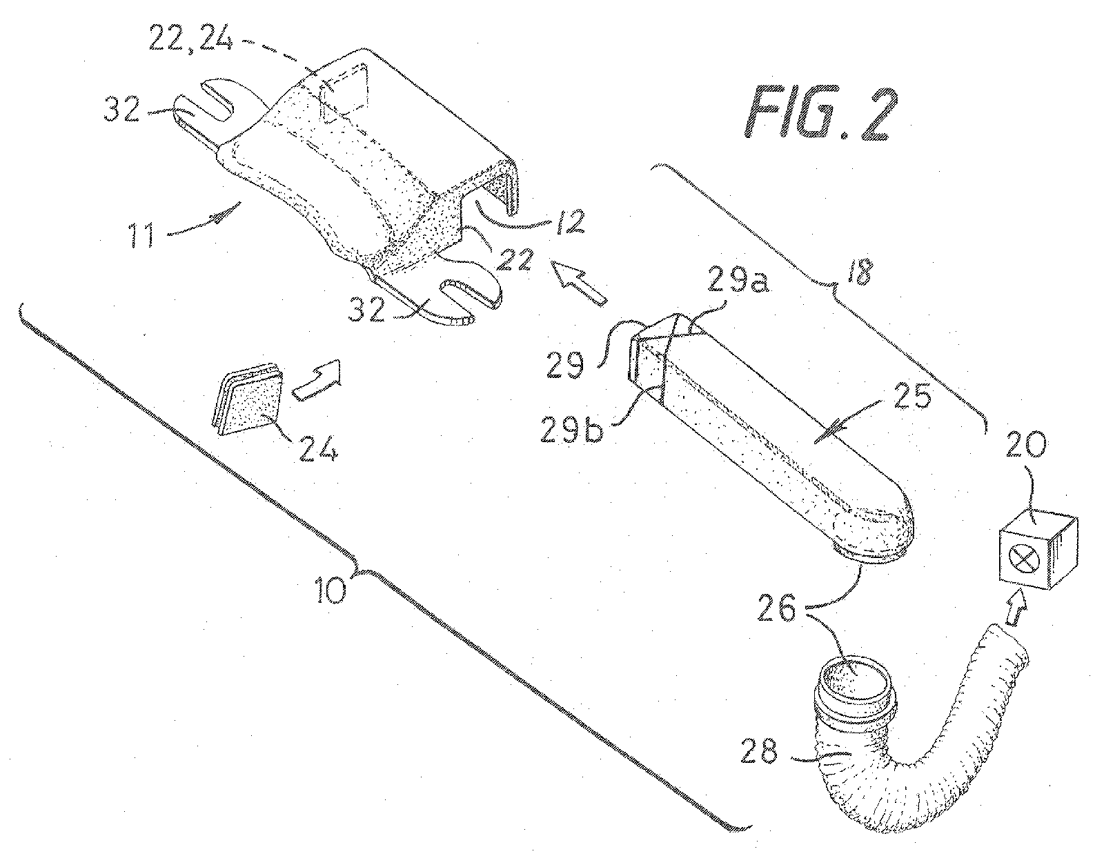
- the illustrated toilet ventilation apparatus 10 consists of a kit of parts which comprises a hollow body 11, generally "h” shaped in side view, providing a chamber 12 therein.
- the longer (and “thinner") limb of the "h” has an opening 13 in its wall that provides an air inlet to the chamber 12.
- the kit also comprises means for mounting the hollow body 11 onto a w.c. pan 14 below the rear of a pan seat 16 (shown in Fig 3), and conduit means 18 for connection between the chamber 12 and an extractor fan 20 (see Fig 2).
- the wall(s) of hollow body 11 of the illustrated example have two exit apertures 22 (on right and left of body 11) for noxious air collected by the chamber, and one blanking member 24 to close the exit aperture 22 that is not in use.
- the conduit means 18 comprises a rigid conduit element 25 selectively connectable to the unblanked one of the exit apertures 22 to convey noxious air from the chamber 12 towards the extractor fan 20.
- the blanking member 24 is grooved around its periphery to slide fittingly and substantially sealingly into the bounding edge of the exit aperture 22 not in use.
- the conduit element 25 comprises an elongate tubular member of generally rectangular cross-section having a depending circular outlet 26 at one end that can be snap-fit coupled to one end of a flexible hose 28 that is coupled by its other end (not shown) to the inlet of the extractor fan 20 in a conventional fashion.
- the end of conduit element 25 remote from outlet 26 has external dimensions providing a tight sliding fit within either of the chamber's two exit apertures 22.
- the mouth 29 of conduit element 25 may ⁇ as shown ⁇ be in a plane at right-angles to the general longitudinal direction of conduit element 25 or, as is preferred, may be selectively cut by the end user at an angle (preferably 45 ° or 135°) to that longitudinal direction along pre-scored or otherwise marked cutting lines 29 a , 29 b .
- conduit element 25 is not inserted fully into the hollow body 11 so as not to close off air flow from the chamber's air inlet 13, through chamber 12, and into mouth 29 of the rigid conduit element 25 from whence it can pass through outlet 26 and flexible hose 28 to the extractor fan.
- the blanking member 24 is shown removed from right-hand-side exit aperture 22, and the rigid conduit element 25 has been cut along score line 29 b before insertion into hollow body 11 through this right-hand-side exit aperture 22.
- the air flow from air inlet 13 to the flexible hose 28 and extractor fan 20 is unimpeded even if the leading edge of the thus cut conduit element 25 abuts against the left-hand-side wall of the chamber 12 or blanking member 24 closing off the opposite exit aperture 22 in that left-hand-side wall.
- the apparatus 10 may be mounted on the upper face of the rear rim of the w.c. pan 14 by one or other of two different mounting means 30. Both means 30 are shown in Fig 3.
- One of the mounting means 30 comprises one or more double-sided adherent pads 31 disposed between the rim of the w.c. pan 14 and the underside of the hollow body 11.
- the adherent material for pads 31 may be that known as "RA25" available from R A International Ltd. of Kings Hill Business Park, Darlaston Road, Wednesbury, West Midlands WS10 7SH.
- the other mounting means 30 may be provided as lateral lugs or flanges 32 protruding outwards from each side of the hollow body 11, each flange 32 having an open (or closed) slot 33 therein to overlie the laterally spaced seat fixing holes 34 that are provided as standard through the rear rim of the w.c. pan. According to B.S. EN37:1999 these two holes 34 should have a diameter of 15mm ⁇ 2mm and a spacing between their centres of 155mm ⁇ 10mm. However, the slots 33 allow for greater variation than these tolerances and enable the body 11 to be fixed in position using seat fixing holes 34 of substantially greater and lesser spacing and/or diameter.
- Such fixing may be by the bolts used to fasten the existing, conventional, or new-style mounting trunnions to the w.c. pan 14, those bolts passing through the seat fixing holes 34 with tightening being effected by wing nuts threaded onto the bolts underneath the rim of the w.c. pan 14.
- such fixing may be by means of a pair of externally threaded, hollow bushes of generally T-shaped cross-section. These serve as hollow “bolts” inserted through the slots 33 and the seat fixing holes 34, and held in position by the "crossbar” of the "T". Nuts screwed on to the externally threaded depending "web” of the "T” fasten the hollow body 11 in position and the seat can then be positioned independently thereon by its own seat fixing bolts inserted through the hollow bushes and, as before, tightened by wing nuts threaded onto these seat fixing bolts from underneath the rear rim of the w.c. pan 14. Such an arrangement allows for the seat to be fastened independently of the ventilation apparatus 10 and potentially with little or no load thereon ⁇ as from a user sitting on the seat ⁇ being imparted onto the hollow body 11.
- the integral lugs or flanges 32 Adjacent the main body 11, the integral lugs or flanges 32 are provided with lines of weakness which permit the flanges to be broken off where circumstances require ⁇ e.g. on certain older seat mounting arrangements to which the apparatus is retro-fitted ⁇ and allow mounting of the hollow body 11 solely by the adherent pads 31.
- any number N of exit apertures 22 can be provided for noxious air collected by the chamber (not just two as for the above-described and illustrated embodiment), and that a corresponding N-1 blanking member 24 would then be provided to close each of the one or more of the exit apertures 22 that is not in use.
- the (or each) blanking member 24 may be initially provided as an integral part of the wall of the hollow body 11 but be readily frangible therefrom, e.g. as by suitable lines of weakness, to permit fitment into the resultant exit aperture 22 of the conduit element 25.
Landscapes
- Health & Medical Sciences (AREA)
- Public Health (AREA)
- Epidemiology (AREA)
- Life Sciences & Earth Sciences (AREA)
- Engineering & Computer Science (AREA)
- Hydrology & Water Resources (AREA)
- Water Supply & Treatment (AREA)
- Toilet Supplies (AREA)
- Ventilation (AREA)
Abstract
Description
- Figure 1
- is a perspective view of apparatus embodying this invention and mounted on a w.c. pan,
- Figure 2
- is an exploded perspective view of the apparatus shown in Fig 1 (minus the pan) viewed from another direction, and
- Figure 3
- is a side view of the embodiment of Fig 1 as mounted below a pan seat.
Claims (5)
- Toilet ventilation apparatus comprising a hollow body providing an internal chamber and having an opening at one end to provide an air inlet to the internal chamber, means for mounting the hollow body onto a w.c. pan below the rear of a pan seat with said opening directed forwardly of the w.c., and conduit means for connection between the chamber and an extractor fan, characterised in that the chamber has a plurality of exit apertures for noxious air collected by the chamber, one or more blanking members to close one or more of the exit apertures not in use, and in that the conduit means comprises a conduit element selectively connectable to any one of the exit apertures and for conveying noxious air from the chamber towards said extractor fan.
- Toilet ventilation apparatus according to Claim 1, wherein the chamber has N exit apertures and N-1 blanking members are provided for closing the or each exit aperture not in use.
- Toilet ventilation apparatus according to Claim 1 or 2, wherein said apparatus is provided in the form of a kit of parts including a plurality of different mounting means selectively utilisable for mounting the hollow body onto a w.c. pan.
- Toilet ventilation apparatus according to Claim 3, wherein said plurality of different mounting means comprises:(a) one or more double-sided adherent pads for disposition between the rim of the w.c. pan and the underside of the hollow body, and(b) a pair of laterally extending lugs integral with, but separable from the hollow body and to be clamped between the pan and the seat by seat mounting bolts.
- Toilet ventilation apparatus according to Claim 4, wherein the mounting means (b) further comprises a pair of hollow bushes of generally T-shaped axial cross-section serving as hollow "bolts" to fasten the lateral lugs of (b) to the w.c. pan and to permit independent attachment of the seat by separate seat mounting bolts extending through the hollow bushes.
Applications Claiming Priority (2)
| Application Number | Priority Date | Filing Date | Title |
|---|---|---|---|
| GB0413825A GB2415204B (en) | 2004-06-19 | 2004-06-19 | Toilet ventilation apparatus and installations |
| GB0413825 | 2004-06-19 |
Publications (2)
| Publication Number | Publication Date |
|---|---|
| EP1607532A2 true EP1607532A2 (en) | 2005-12-21 |
| EP1607532A3 EP1607532A3 (en) | 2007-01-03 |
Family
ID=32750283
Family Applications (2)
| Application Number | Title | Priority Date | Filing Date |
|---|---|---|---|
| EP05105400A Withdrawn EP1607532A3 (en) | 2004-06-19 | 2005-06-17 | Toilet ventilation apparatus and installations |
| EP05105402A Withdrawn EP1607533A3 (en) | 2004-06-19 | 2005-06-17 | Toilet ventilation apparatus and installations |
Family Applications After (1)
| Application Number | Title | Priority Date | Filing Date |
|---|---|---|---|
| EP05105402A Withdrawn EP1607533A3 (en) | 2004-06-19 | 2005-06-17 | Toilet ventilation apparatus and installations |
Country Status (3)
| Country | Link |
|---|---|
| US (1) | US20070000035A1 (en) |
| EP (2) | EP1607532A3 (en) |
| GB (2) | GB2414744B (en) |
Families Citing this family (5)
| Publication number | Priority date | Publication date | Assignee | Title |
|---|---|---|---|---|
| PL216684B1 (en) * | 2006-06-20 | 2014-05-30 | Ryszard Kret | Air release methos from lavatory bowl and device for release of air from the lavatory bowl |
| US20080256692A1 (en) * | 2007-04-17 | 2008-10-23 | Bruce Edward Barton | Novel Toilet Air Treatment Device |
| US20090229045A1 (en) * | 2008-03-11 | 2009-09-17 | Ramon Ramos | Toilet seat ventilation system |
| US8434170B1 (en) * | 2009-03-04 | 2013-05-07 | Ramon Ramos | Toilet ventilation system |
| US12065818B2 (en) * | 2022-05-11 | 2024-08-20 | Jordon Wilson | Universal toilet odor removal system |
Family Cites Families (18)
| Publication number | Priority date | Publication date | Assignee | Title |
|---|---|---|---|---|
| US1862085A (en) * | 1931-01-29 | 1932-06-07 | Hertzog John | Ventilator fan for water closets |
| US1861501A (en) * | 1931-04-27 | 1932-06-07 | Jesse P Lowther | Foul air exhauster |
| US2214200A (en) * | 1938-09-28 | 1940-09-10 | Jesse P Lowther | Toilet ventilator |
| US2238461A (en) * | 1939-11-09 | 1941-04-15 | James W Carman | Means for purifying toilet gases |
| US2309885A (en) * | 1941-07-30 | 1943-02-02 | James W Carman | Air treatment device |
| US3108289A (en) * | 1962-07-20 | 1963-10-29 | Claude V Smith | Toilet ventilator |
| FR1546807A (en) * | 1967-10-13 | 1968-11-22 | Air intake hopper, adaptable to toilet bowls. | |
| US3649972A (en) * | 1970-01-30 | 1972-03-21 | Edward W Sowards | Ventilating system |
| US3849808A (en) * | 1973-06-21 | 1974-11-26 | C Olson | Toilet exhaust means |
| US4375704A (en) * | 1980-02-25 | 1983-03-08 | Smith Donald L | Unitary assembly for attachment to a toilet for ventilating the same |
| US5054130A (en) * | 1990-05-21 | 1991-10-08 | Wilson Thomas R | Toilet deodorizing device |
| DE19605898A1 (en) * | 1996-02-17 | 1997-08-21 | Bernd Welsch | Odour removal device for lavatories etc. |
| US5806104A (en) * | 1996-08-27 | 1998-09-15 | Hand; William W. | Toilet deodorizing device utilizing liquid deodorant |
| US6463595B2 (en) * | 2000-01-14 | 2002-10-15 | Delpriss Management Services, Inc. | Toilet ventilation system |
| US6779204B1 (en) * | 2000-11-17 | 2004-08-24 | Egor Ciotic | Portable venting commode |
| US20030019019A1 (en) * | 2001-07-25 | 2003-01-30 | Blanch Kris A. | Toilet odor removal system and method therefor |
| US6496986B1 (en) * | 2001-11-01 | 2002-12-24 | Ray Allen Lumsden | Toilet bowl venting device |
| US6550072B1 (en) * | 2002-03-08 | 2003-04-22 | Derrick Ware | Bowl ventilation apparatus |
-
2004
- 2004-06-19 GB GB0503704A patent/GB2414744B/en not_active Expired - Fee Related
- 2004-06-19 GB GB0413825A patent/GB2415204B/en not_active Expired - Fee Related
-
2005
- 2005-06-17 US US11/156,007 patent/US20070000035A1/en not_active Abandoned
- 2005-06-17 EP EP05105400A patent/EP1607532A3/en not_active Withdrawn
- 2005-06-17 EP EP05105402A patent/EP1607533A3/en not_active Withdrawn
Also Published As
| Publication number | Publication date |
|---|---|
| EP1607533A2 (en) | 2005-12-21 |
| GB0413825D0 (en) | 2004-07-21 |
| GB2415204A (en) | 2005-12-21 |
| EP1607532A3 (en) | 2007-01-03 |
| GB2414744A (en) | 2005-12-07 |
| GB2415204B (en) | 2006-04-19 |
| US20070000035A1 (en) | 2007-01-04 |
| GB0503704D0 (en) | 2005-03-30 |
| EP1607533A3 (en) | 2007-01-03 |
| GB2414744B (en) | 2006-04-19 |
Similar Documents
| Publication | Publication Date | Title |
|---|---|---|
| US7610726B2 (en) | Housing assembly | |
| US4175293A (en) | Toilet bowl odor removing apparatus and hinge | |
| US5199111A (en) | Toilet odor removing apparatus | |
| US8239973B1 (en) | Toilet ventilation apparatus | |
| US4085470A (en) | Ventilated toilet device | |
| US9745732B2 (en) | Toilet odor control device | |
| AU714333B3 (en) | Improvements in the ventilation of toilets | |
| EP1607533A2 (en) | Toilet ventilation apparatus and installations | |
| US20060021120A1 (en) | Odorless toilet | |
| US5875496A (en) | Toilet duct ventilation system | |
| US5839127A (en) | Odor extractor apparatus | |
| US5255395A (en) | Ventilating system for toilet bowl | |
| US5179737A (en) | Odor remover device | |
| US20120186007A1 (en) | Ventilation device | |
| US6158058A (en) | Ventilated toilet | |
| US7120942B2 (en) | Toilet ventilation system | |
| US20100058525A1 (en) | Toilets | |
| EP1329661A3 (en) | Cleanable pipe for discharge system | |
| US5136729A (en) | Odor remover device | |
| GB2126263A (en) | Ventilating water closets | |
| US20060096013A1 (en) | Odorless commode | |
| CA2347273A1 (en) | System for directly venting odour air from toilet bowl | |
| GB2140052A (en) | Ventilating apparatus for a toilet pan | |
| US20120260411A1 (en) | Commode ventilator | |
| DE10326340A1 (en) | Wall-mounted toilet bowl has air extraction openings, over the highest water level and the flushing pipe inlet, to carry air into a chamber for extraction by a fan to remove odors |
Legal Events
| Date | Code | Title | Description |
|---|---|---|---|
| PUAI | Public reference made under article 153(3) epc to a published international application that has entered the european phase |
Free format text: ORIGINAL CODE: 0009012 |
|
| AK | Designated contracting states |
Kind code of ref document: A2 Designated state(s): AT BE BG CH CY CZ DE DK EE ES FI FR GB GR HU IE IS IT LI LT LU MC NL PL PT RO SE SI SK TR |
|
| AX | Request for extension of the european patent |
Extension state: AL BA HR LV MK YU |
|
| PUAL | Search report despatched |
Free format text: ORIGINAL CODE: 0009013 |
|
| AK | Designated contracting states |
Kind code of ref document: A3 Designated state(s): AT BE BG CH CY CZ DE DK EE ES FI FR GB GR HU IE IS IT LI LT LU MC NL PL PT RO SE SI SK TR |
|
| AX | Request for extension of the european patent |
Extension state: AL BA HR LV MK YU |
|
| AKX | Designation fees paid |
Designated state(s): AT BE BG CH CY CZ DE DK EE ES FI FR GB GR HU IE IS IT LI LT LU MC NL PL PT RO SE SI SK TR |
|
| STAA | Information on the status of an ep patent application or granted ep patent |
Free format text: STATUS: THE APPLICATION IS DEEMED TO BE WITHDRAWN |
|
| 18D | Application deemed to be withdrawn |
Effective date: 20070704 |